Loading ...
Loading ...
Loading ...
Rinnai Australia 35 Installation Manual
WATER CONTROLLER INSTALLATION
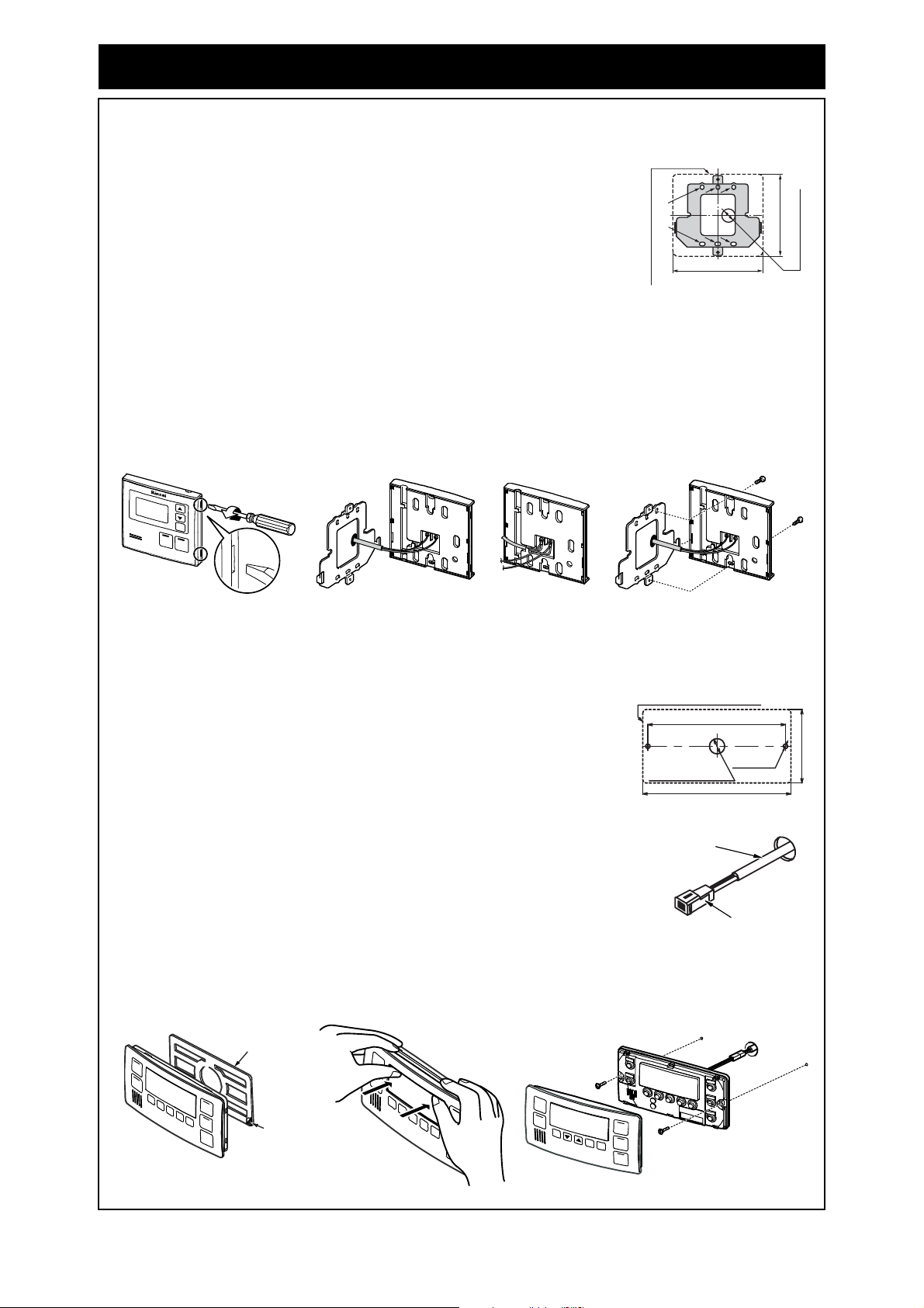
FITTING THE ‘DELUXE KITCHEN’ WATER CONTROLLER (MC-100V)
FITTING THE ‘DELUXE BATHROOM’ WATER CONTROLLER (BC-100V)
1. Determine the most suitable position for the water controller (see notes page 33).
2. Use the wall mounting bracket as a template to mark and drill 3
holes, locating the cable access as shown in (Fig. 1).
3. Fix the mounting bracket to the wall using the appropriate fixings.
4. Run the cable through the hole in the wall.
5. Carefully remove face plate from the water controller, using a screw
driver (Fig. 2).
Fig.1
6. Connect the cable to the water controller as shown in (Fig 3). At this point cables from other
controllers (if fitted) may also be connected to the screw terminals of the Kitchen water controller
(Fig. 4) eliminating the need for multiple cable runs directly to the water heater. Water controllers
are not polarity sensitive. Feed any excess cable lengths into the wall cavity to avoid the pinching
of cables between the wall and the controller.
7. Fasten the controller to the wall mounting bracket as shown in (Fig. 5). Avoid the over-tightening
of fixings as this may cause damage. Once secured replace the face plate.
Fig. 2 Fig. 3
Fig. 4 Fig. 5
1. Determine the most suitable position for the water controller (see notes page 33).
2. Mark and drill 3 holes, locating the cable access as shown in (Fig. 1).
3. When running a cable through the access hole ensure the connector
end of the cable is located nearest to the controller (Fig. 2).
4. Affix the double sided self-adhesive seal to the back of the water
controller (Fig. 3).
5. Carefully remove the face plate from the water controller, do this by
placing your thumbs on the front of the digital display and while
hooking your fingers behind top of plate and gently push as shown in
(Fig. 4), DO NOT use a screwdriver as this may damage the
controller.
6. Connect the cable to the water controller. Feed any excess cable
lengths into the wall cavity to avoid the pinching of cables between
the wall and the controller.
Fig. 1
Fig. 2
7. Fix the controller to the wall using the appropriate fixings as shown in (Fig. 5), avoid over-
tightening of fixings as this may cause damage. Once secured replace the face plate.
Fig. 3 Fig. 4 Fig. 5
Outline of Water Controller
Screw Securing Points
128
120
Ø20 Cable Access
181
202
Outline of Water Controller
104
Securing
Screw
Ø20 Cable Access
Connector
Controller Cable
Backing Seal
Remove film
to expose
self-adhesive
Loading ...
Loading ...
Loading ...