Loading ...
Loading ...
Loading ...
Rinnai Australia 31 Installation Manual
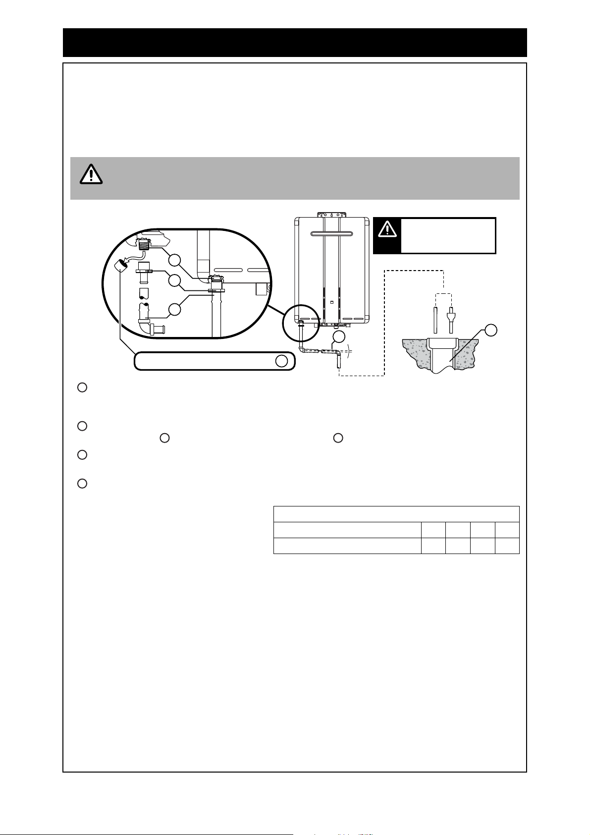
CONDENSATE DRAIN (REU-KM’ MODELS ONLY)
The INFINITY & HDC REU-KM’ range of water heaters generate condensate continuously at a rate
of up to 5 litres per hour as a by-product of highly efficient gas burner system. This condensate must
be drained via a pipe to a suitable point of discharge. Because the condensate is a by-product of gas
combustion it is mildly acidic. For this reason copper tube and fittings MUST NOT be used as it will
corrode. Instead, Rinnai recommend plastic pipes and fittings such as Unplasticised Polyvinyl
Chloride (UPVC) or Polyethylene (PE) which is commonly used for irrigation piping.
IMPORTANT CONSIDERATIONS FOR THE CONDENSATE DRAIN PIPE
Water heater drain outlet connection, R½” (15 mm) BSP male. Condensate drain outlet
connection, 1/2” (15mm) BSP male nylon (Note: the black plastic shipping cap MUST BE
removed from the condensate drain outlet prior to water heater operation).
PE R½” BSP (15 mm) female to barbed irrigation system connector (13 – 19mm) or equivalent
plastic fitting. Drain pipe and fittings to match item .
Continuous fall (of at least 2°) from water heater to discharge point. Lengths and bends in
accordance with ‘LENGTH AND CHANGES OF DIRECTION’ below.
Suitable points of discharge are deemed to be drains, sewers or pits. DO NOT discharge onto
electrical connections, earth stakes, copper pipes, concrete paths or into a pond.
INSTALLATION
(a) The drain line MUST NOT discharge onto electrical connections, earth stakes, copper pipes,
concrete paths or into a pond.
(b) The point of discharge from each drain line shall be located so that the release of condensate
does not cause a nuisance, is readily discernible and incurs no risk of damage to the building.
In view of (a) and (b), suitable points of discharge are deemed to be drains, sewers or pits.
(c) There shall be no tap, valve or other restrictions in any line.
(d) Each line shall fall continuously from the valve to the approved point of discharge.
(e) Drain lines shall not discharge into a storage water heater safe tray.
(f) The end of the condensate drain line shall be:
(i) not lower than 200 mm or higher than 300 mm above an unpaved surface; or
(ii) not lower than 75 mm or higher than 300 mm above a gravel pit not less than 100 mm in
diameter in a paved surface.
(g) Where discharging over a tundish or gully trap, drain lines shall have an air gap of a size at least
twice the diameter of the drain line.
The content of AS/NZS 3500 ‘Temperature / Pressure Relief and Expansion Control
Valve Drain Lines’ has been used as a guide in preparing these considerations.
LENGTH AND CHANGES OF DIRECTION
Maximum length and changes of direction
greater than 45° should be as follows:
Lengths and changes of direction
Max length (Metres) 9 8 7 6
Max changes of direction >45° 3 4 5 6
NOTE
2°
D
B
A
C
E
A
Remove cap from condensate drain outlet
Condensate drain applies to
both internal and external
models, the external model
is shown in this illustration.
NOTE
A
B
C
B
D
E
Loading ...
Loading ...
Loading ...