Loading ...
Loading ...
Loading ...
Rinnai Australia 33 Installation Manual
WATER CONTROLLER INSTALLATION
RINNAI WATER CONTROLLERS
Water controllers are available as an optional extra. Universal and Deluxe water controllers can be
used together and will function as described in the Operation Section of this manual. Please refer to
page 10 to confirm the maximum number and combination of water controllers that can be fitted.
POSITIONING OF WATER CONTROLLERS
Water controllers must be installed in shaded and clean locations. They should be fitted out of reach
of children (suggested height from floor to be at least 1500 mm). BC-100V water controllers are water
resistant, however, durability is improved when positioned outside the shower recess. All deluxe water
controllers must be installed at least 400 mm above the highest part of a sink, basin or bath.
WATER CONTROLLER CABLES
Water controllers operate at extra low voltage (12 Volts DC) which is supplied from the water heater.
Each Water controller comes supplied with 15 m of electrical cable. The appliance end of the cables
are fitted with spade terminals. Extension cabling is available from Rinnai.
Other manufacturers water controllers are NOT compatible with Rinnai water
heaters. Water controllers MUST NOT be used with any Solar Boost water heater.
Rinnai water controllers brought in from other countries are not compatible with
Rinnai appliances sold in Australia.
• Do not install water controllers near a heat source, such as a cook top, stove
or oven. Heat, steam, smoke and hot oil may cause damage.
• Do not install water controllers in direct sunlight.
• The MC-100V water controller MUST NOT be installed in a bathroom.
• Do not install water controllers outdoors unless protection from dust ingress
and sunlight are provided.
• Do not install water controllers against a metal wall unless the wall is earthed
in accordance with AS/NZS3000.
• Water controllers MUST NOT be installed where chemicals such as benzine,
alcohol, turpentine or other similar chemicals are in use.
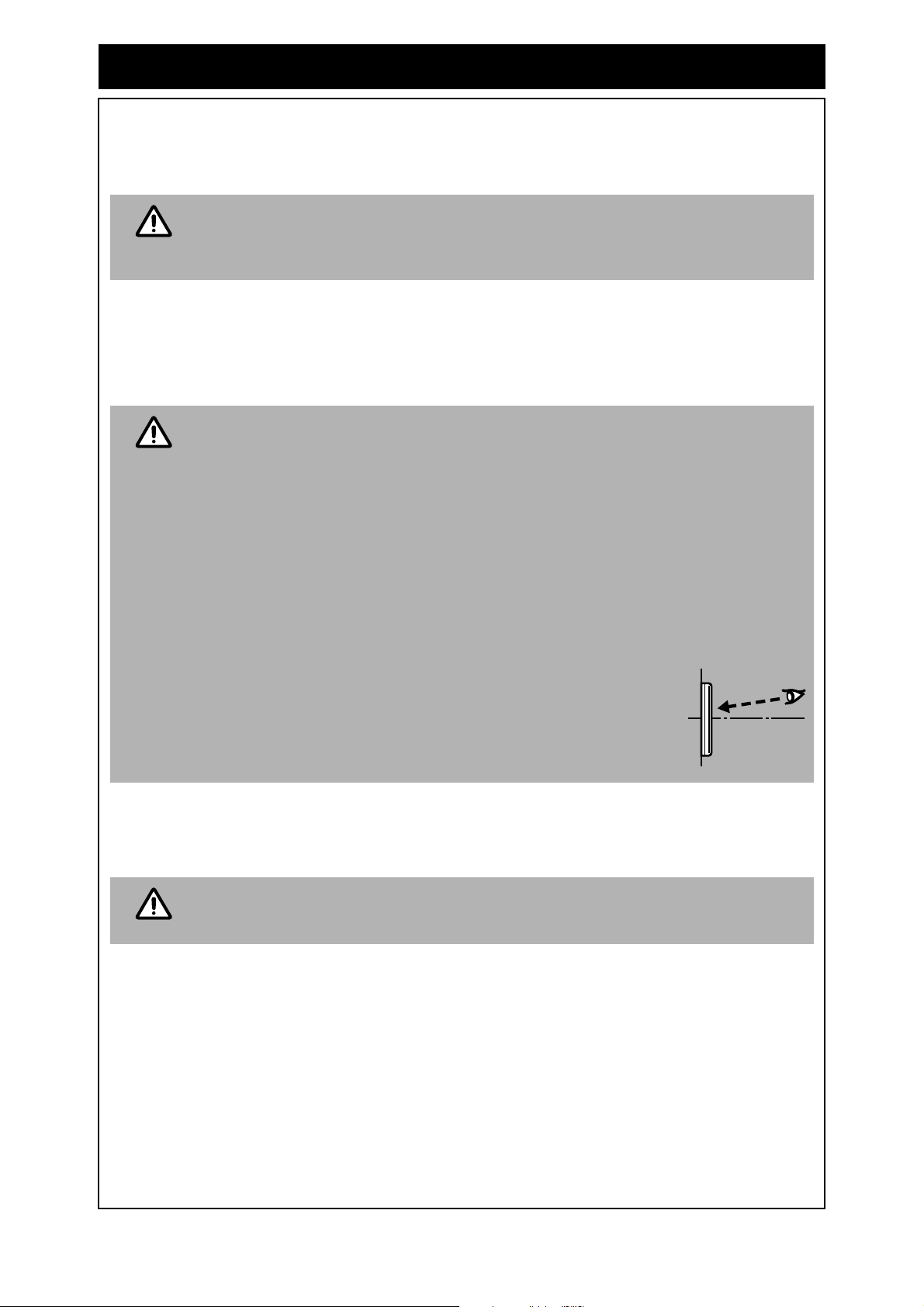
POSITIONING CONSIDERATIONS FOR THE MC-100V WATER CONTROLLER.
The MC-100V uses a Liquid Crystal Display (LCD) for the digital
monitor. Light reflections can make the LCD difficult to see at
direct eye level.
For best results when Installing the MC-100V mount the water
controller lower than your eye-level to avoid these light
reflections.
Alternatively two core sheathed (double insulated) flex with minimum cross-
sectional area of 0.5 mm² may be used. Maximum individual cable runs should
not exceed 50 m.
FITTING THE ‘UNIVERSAL’ WATER CONTROLLER (MC-91Q)
1. Determine the most suitable position for the water controller.
2. Mark and drill 3 holes, locating the cable access as shown in (Fig. 1).
3. When running cable through the access hole ensure the connector end of the cable is located
nearest to the controller (Fig. 2).
4. Carefully remove face plate from the water controller, using a screw driver (Fig. 3).
5. Connect the cable to the water controller. Feed any excess cable lengths into the wall cavity to
avoid the pinching of cables between the wall and the controller.
6. Fix the water controller to the wall using the appropriate fixings as shown in (Fig. 4).
NOTE
NOTE
NOTE
Loading ...
Loading ...
Loading ...