Loading ...
Loading ...
Loading ...
COMMISSIONING
79
5. Turn off the hot tap.
6. Switch off the electrical supply at the power outlet to the water heater.
7. Remove the screws holding the front panel to the jacket.
8. Gently disengage the front panel and pull forward to remove from the water heater.
9. Switch on the electrical supply at the power outlet to the water heater.
Note: Wait ten (10) seconds for the electronic system to initialise.
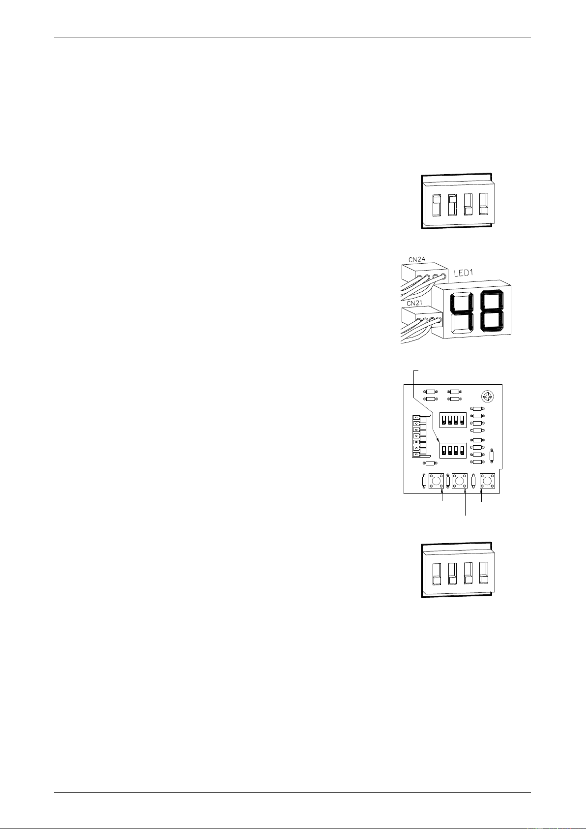
10. Switch dip switches 1 and 2 to the on (up) position on the DIP 2 set
of DIP switches on the I.C. Board.
The temperature setting of ‘48’ will show on the LED display, if this
has not previously been adjusted.
11. Press the MAX button once to increase the preset outlet
temperature setting to the next increment.
Each press of the MAX button will increase the temperature setting
by one increment. The increments are:
48, 50, 51, 52.
The MAX button is located underneath the DIP 1 and DIP 2 set of
DIP switches.
12. Switch dip switches 1 and 2 to the off (down) position on the DIP 2
set of DIP switches on the I.C. Board.
The LED display will go blank.
Note: Wait ten (10) seconds for the setting to be saved.
13. Repeat steps 2 to 5.
if the water temperature is still below 50°C and requires to be
increased, repeat steps 10 to 12, followed by steps 2 to 5 until
an acceptable water temperature not exceeding 50°C is
measured at the same hot tap.
if the water temperature exceeds 50°C, then;
switch dip switches 1 and 2 to the on (up) position on the
DIP 2 set of DIP switches on the I.C. Board.
press the MIN button once to decrease the preset outlet
temperature setting to the next increment.
Each press of the MIN button will decrease the preset
temperature by one increment.
The MIN button is located underneath the DIP 1 and DIP 2
set of DIP switches and to the left of the MAX button.
Switch dip switches 1 and 2 to the off (down) position on the DIP 2 set of DIP switches on the
I.C. Board.
Note: Wait ten (10) seconds for the setting to be saved.
repeat steps 2 to 5 to confirm the water temperature does not exceed 50°C.
14. Switch off the electrical supply at the power outlet to the water heater.
15. Refit the front panel and screws to the water heater.
16. Reconnect the controller cables (if a temperature controller is fitted), by following steps 4 to 6 of the
procedure “Connecting the Controller(s) to the Water Heater” on page 71.
17. Switch on the electrical supply at the power outlet to the water heater.
1
2
3
4
ON
DIP SWITCHES
OUTLET TEMPERATURE COMPENSATION
ADJUSTMENT SETTINGS
CONTINUOUS FLOW WATER HEATER
886 024 MODELS
SK6864-2
DIP2
OFF ON
1
2
3
4
DIP1
OFF ON
1
2
3
4
1
2
3
4
1
2
3
4
ON
ON
DIP2
OFF ON
1
2
3
4
1
2
3
4
ON
DIP1
OFF ON
1
2
3
4
SK6864-4
LED Display
Continuous Flow Water Heater
86, 87, 88 Series, 024, 027 Models
MIN. BUTTON
MAX. BUTTON
ADJUSTER
BUTTON
DIP 2 SET OF
DIP SWITCHES
DIP SWITCH AND ADJUSTMENT BUTTONS
CONTINUOUS FLOW WATER HEATER
86, 87, 88 SERIES, 024, 027 MODELS
SK6864-3
1 2 3 4
OFF ON
DIP1
1 2 3 4
ON
1 2 3 4
OFF ON
DIP2
MIN MAX ADJ
1 2 3 4
ON
1
2
3
4
ON
DIP SWITCHES
OUTLET TEMPERATURE COMPENSATION
ADJUSTMENT SETTINGS
CONTINUOUS FLOW WATER HEATER
886 024 MODELS
SK6864-2
DIP2
OFF ON
1
2
3
4
DIP1
OFF ON
1
2
3
4
1
2
3
4
1
2
3
4
ON
ON
DIP2
OFF ON
1
2
3
4
1
2
3
4
ON
DIP1
OFF ON
1
2
3
4
Loading ...
Loading ...
Loading ...