Loading ...
Loading ...
Loading ...
INSTALLATION – WATER HEATER
47
INSTALLATION WITHIN A COVERED AREA
The water heater must be located such that the installation meets the requirements of either AS 5601 or
AS/NZS 5601.1 as applicable under local regulations. There must be sufficient ventilation so the water
heater has an adequate supply of combustion air and the flue products are dispersed safely. It is the
licensed installer’s responsibility to ensure the installation complies with the relevant sections of the
prevailing Gas installations Standard.
Installation of this water heater is permitted within a covered area open on at least two sides, if its flue
terminal is located to ensure a free flow of air across it is achieved.
AS/NZS 5601.1 also allows the installation of a continuous flow gas water heater within a covered area open
on one side only if the flue terminal is within 500 mm of the opening, is discharging in the direction of the
opening, there are no openings into the building along the wall within the 500 mm distance and the terminal
is located to ensure a free flow of air across it is achieved.
PIPE COVER
The pipe work to the water heater can be housed within a pipe cover. A pipe cover kit (PN 299830) is
available for such an installation. Refer to the installation instructions which accompany the pipe cover kit.
RECESS INSTALLATION
The water heater can be installed recessed into a wall. A recess box (PN 299831) is available for such an
installation. Refer to the installation instructions which accompany the recess box kit for information on its
installation.
An additional rating label is supplied attached to the inside of the front cover of the water heater. This is for a
service person to access the water heater details when required. The rating plate on the side of the water
heater should be moved to or the information copied onto either the front panel of the water heater or to
another position which is visible when the water heater is installed so the householder can access the water
heater details when required.
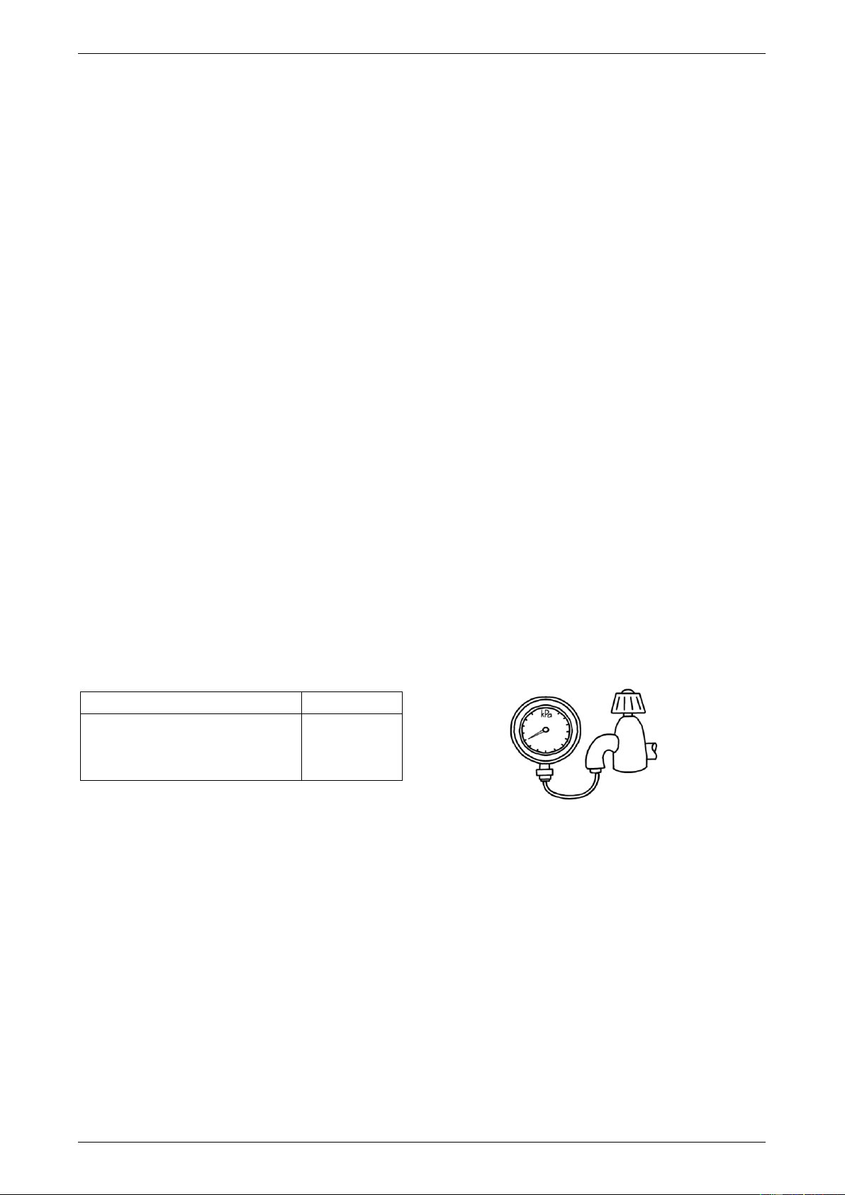
MAINS WATER SUPPLY
Where the mains water supply pressure exceeds that shown in the table below, an approved pressure
limiting valve that does not have non-return valve characteristics (such as an RMC PSL series valve) is
required and should be fitted as shown in the installation diagram (refer to page 56).
Model
27
Relief valve setting
1750 kPa
Max. mains supply pressure
1000 kPa
Min. mains supply pressure *
140 kPa
* minimum water supply pressure required to achieve the
rated flow and performance
Notes:
It is not recommended to install this water heater with a low pressure water supply.
A minimum water supply pressure of 140 kPa is required to achieve the rated flow and performance of
the water heater.
If this water heater is installed as an in-series gas booster for a solar water heater, the maximum water
supply pressure to the solar water heater, without an expansion control valve (ECV), is generally
800 kPa, however it may be less than this for some models. Refer to the Owner’s Guide and Installation
Instructions supplied with the solar water heater for maximum mains supply pressure details.
If sludge or foreign matter is present in the water supply, it is recommended a suitable filter be
incorporated in the cold water line to the water heater.
This water heater is not suitable for connection to bore water or spring water unless a water treatment
device is fitted.
Refer to “Water Supplies” on page 41 for further information on water chemistry.
Loading ...
Loading ...
Loading ...