Loading ...
Loading ...
Loading ...
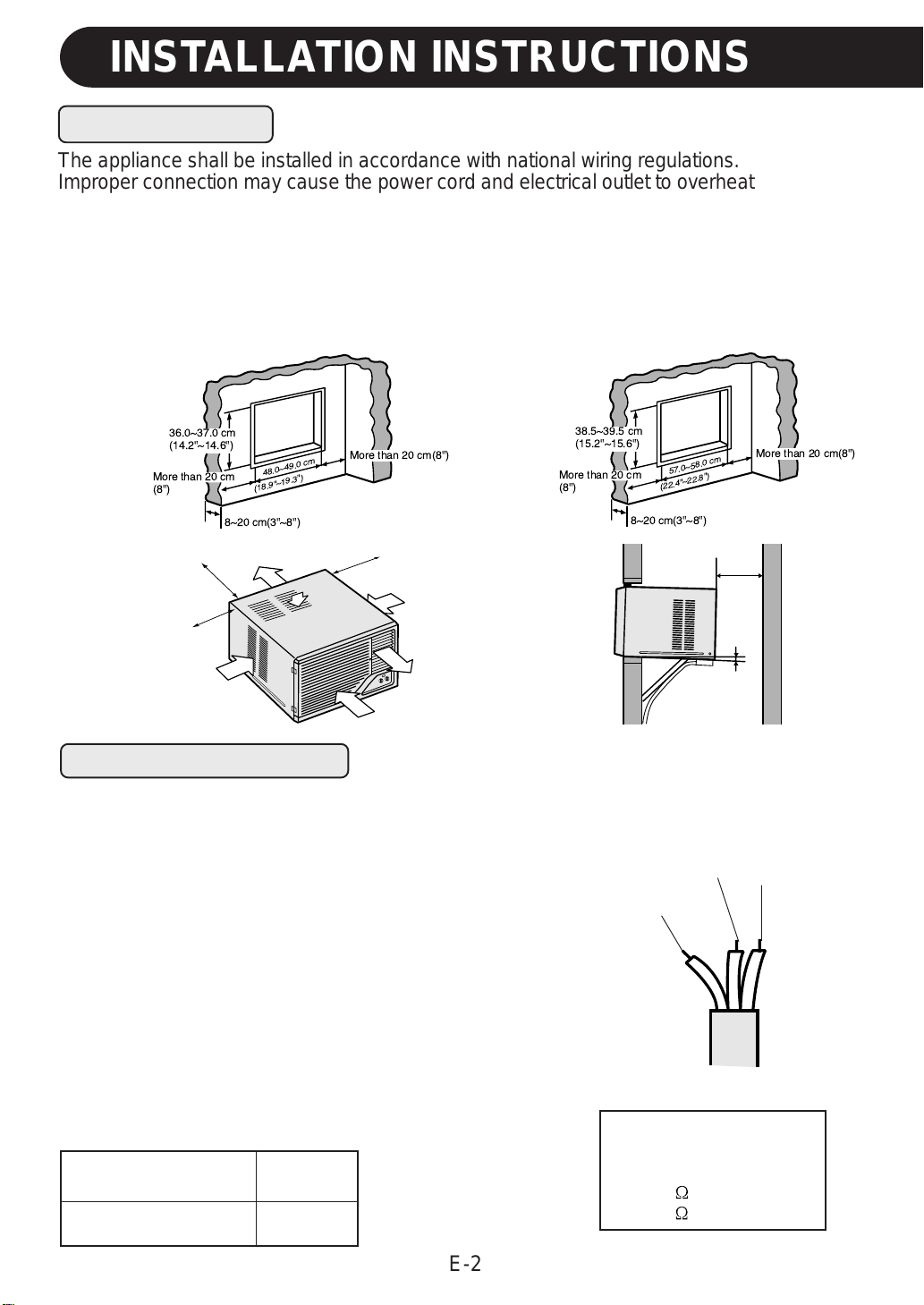
57.0~58.0 cm
(22.4"
~22.8"
)
8~20 cm(3"~8")
38.5~39.5 cm
(15.2"~15.6")
More than 20 cm
(8")
More than 20 cm(8")
48.0~49.0 cm
(18.9"
~19.3"
)
8~20 cm(3"~8")
36.0~37.0 cm
(14.2"~14.6")
More than 20 cm
(8")
More than 20 cm(8")
E-2
INSTALLATION INSTRUCTIONS
The appliance shall be installed in accordance with national wiring regulations.
Improper connection may cause the power cord and electrical outlet to overheat or fire.
Install the air conditioner to the opening dimensions shown below.
Never install the unit where any of the air inlet is blocked.
The air conditioner should be installed with a strong external support to minimize noise and
vibration, and for the purpose of safe installation, repair, replacement and secure positioning.
Avoid installing the air conditioner where it is exposed to direct sunlight.
LOCATION
Live
(brown)
Grounding wire
(green&yellow)
More than 40cm
(16")
About 1cm
(3/8")
Air inlet
Air outlet
Air inlet
More than 20cm(8")
Air inlet
Air outlet
More than 40cm(16")
Air inlet
More than 20cm(8")
For safe, trouble free operation, connect the power
cord of the unit to a properly rated independent circuit
with a time delay fuse or a circuit breaker. See chart
for proper amp ratings for each model.
FUSE
GROUNDING
AF-A07CE,AF-A09CE
AF-A12CE
Neutral
(blue)
WARNING : THIS APPLIANCE MUST BE
GROUNDED.
Fit a disconnect switch, having a contact separation of
at least 3mm in all poles, to the electricity power line.
Connect the brown wire of the power supply cord to the
live terminal, and the grounding wire (green and yellow)
to the grounding terminal of the electrical outlet. The
remaining wire should be connected to the neutral
terminal of the electrical outlet.
POWER CABLING
Maximum Permissible
System Impedance
0.41 ( AF-A09CE )
0.25 ( AF-A12CE )
10 amp.
15 amp.
AF-A12CE
AF-A07CE, AF-A09CE
Downloaded from: http://www.usersmanualguide.com/
Loading ...
Loading ...
Loading ...