Read all safety warnings and instructions. Failure to follow the warnings
and instructions may result in serious injury. Save all warnings and
instructions for future reference.
INSTALLATION AND USER’S GUIDE
ITEM: 75058
2-WHEEL SUCTION POOL CLEANER
DANGER
75058

THIS PAGE INTENTIONALLY LEFT BLANK

DISCLAIMER
TROUBLESHOOTING
INSTALLATION
PRODUCT DIMENSIONS
PACKAGE CONTENTS
OVERVIEW (PRODUCT INFORMATION)
GENERAL SAFETY
Legends and Symbols
IMPORTANT SAFETY INSTRUCTIONS
TABLE OF CONTENTS
TABLE OF CONTENTS
1
STEP 3: POOL SKIMMER / SUCTION CONNECTION
STEP 2: CONNECTING HOSES AND HOSE FLOAT
STEP 1: PRIOR TO INSTALLATION
Customer Service
Disclaimer
REPLACING TIRES
UNCLOGGING THE CLEANER
ROUTINE MAINTENANCE
UTILIZING THE PROGRAMMABLE FEATURE
ADJUSTING TIRE BUMPER HEIGHT
CUSTOMER SERVICE
If you have any questions about ordering our pool pumps and replacement parts or pool products,
please feel free to contact us using the following contact information:
Customer Service and Technical Support
Phone: (909) 628-0880
Email: [email protected]
Hours of Operation: Monday – Friday, 9AM – 4PM (CST)
1
2
2
3
4
4
5
6
6
7-10
11
12
13-15
16
16
16
16
17
18
19
20
20
20
MAINTENANCE
STEP 3: POOL SKIMMER / SUCTION CONNECTION (CONTINUED)
REPLACEMENT PARTS
2
IMPORTANT SAFETY INSTRUCTIONS
For safety reasons, children should not be allowed to use this product.
Failure to comply with all instructions and warnings may lead to severe bodily injury
or even death. It is strongly recommended that only a qualified pool service professional install and
service this product. Prior to using this product, installers, operators, and owners must carefully review
these warnings and all instructions provided in the owner's manual. It is essential to leave these
warnings and the owner's manual with the pool owner for their reference and safety.
ATTENTION INSTALLER: This manual contains vital information regarding the installation, operation,
and safe use of this product. It is essential to provide this manual to the end user of the product. Failure
to read and follow all instructions could lead to severe injuries.
USE OF NON-XTREMEPOWERUS REPLACEMENT PARTS VOIDS WARRANTY
DANGER: Ignoring these hazards can result in death, severe personal injury, or
significant property damage.
WARNING: Indicates potential hazards that can result in severe personal injury,
death, or significant property damage. Ignoring these warnings presents a real
danger.
CAUTION: Indicates potential hazards that can result in minor or moderate personal
injury, property damage, or actions that are unpredictable and unsafe. Ignoring these
cautions presents a potential hazard.
NOTICE: This label indicates important special instructions that are not directly
related to hazards.
This guide provides instructions for installing and using the product. If you have any questions about
the product, please contact XtremepowerUS.
This guide contains important information about safely installing and operating this product. After
installation, make sure to share this information with the owner/operator or leave it with them for their
reference.
Legends and Symbols
When you come across the safety-alert symbol on the product or in this manual, pay attention to the
following signal words and remain vigilant about the potential for personal injury.
IMPORTANT SAFETY INSTRUCTIONS
DANGER
WARNING
WARNING
CAUTION
NOTE
DANGER
3
IMPORTANT SAFETY INSTRUCTIONS
GENERAL SAFETY
WARNING
• The pool cleaner is for adult use only; children should not operate it.
• Store the pool cleaner out of reach of children and away from pets.
• Cover dedicated suction ports (vac port or automatic pool cleaner port) when not in use.
• Avoid direct contact with the cleaner or hose to prevent severe injuries.
• The suction force can trap individuals underwater, posing a drowning risk.
• Do not enter the pool while the cleaner is operational.
READ BEFORE USE
DANGER
CAUTION
NOTE
• Stop the pump before entering the pool to avoid injuries from moving parts.
• Detach the hose and move the cleaner to an unused area of the pool for swimmer safety.
• Remove the hose from the pool if it obstructs swimmers.
• Prohibit play or use of the pool cleaner or its hose around individuals, especially children.
• Inform all pool users about the dangers associated with the hose, cleaner, and suction ports.
4
OVERVIEW (PRODUCT INFORMATION)
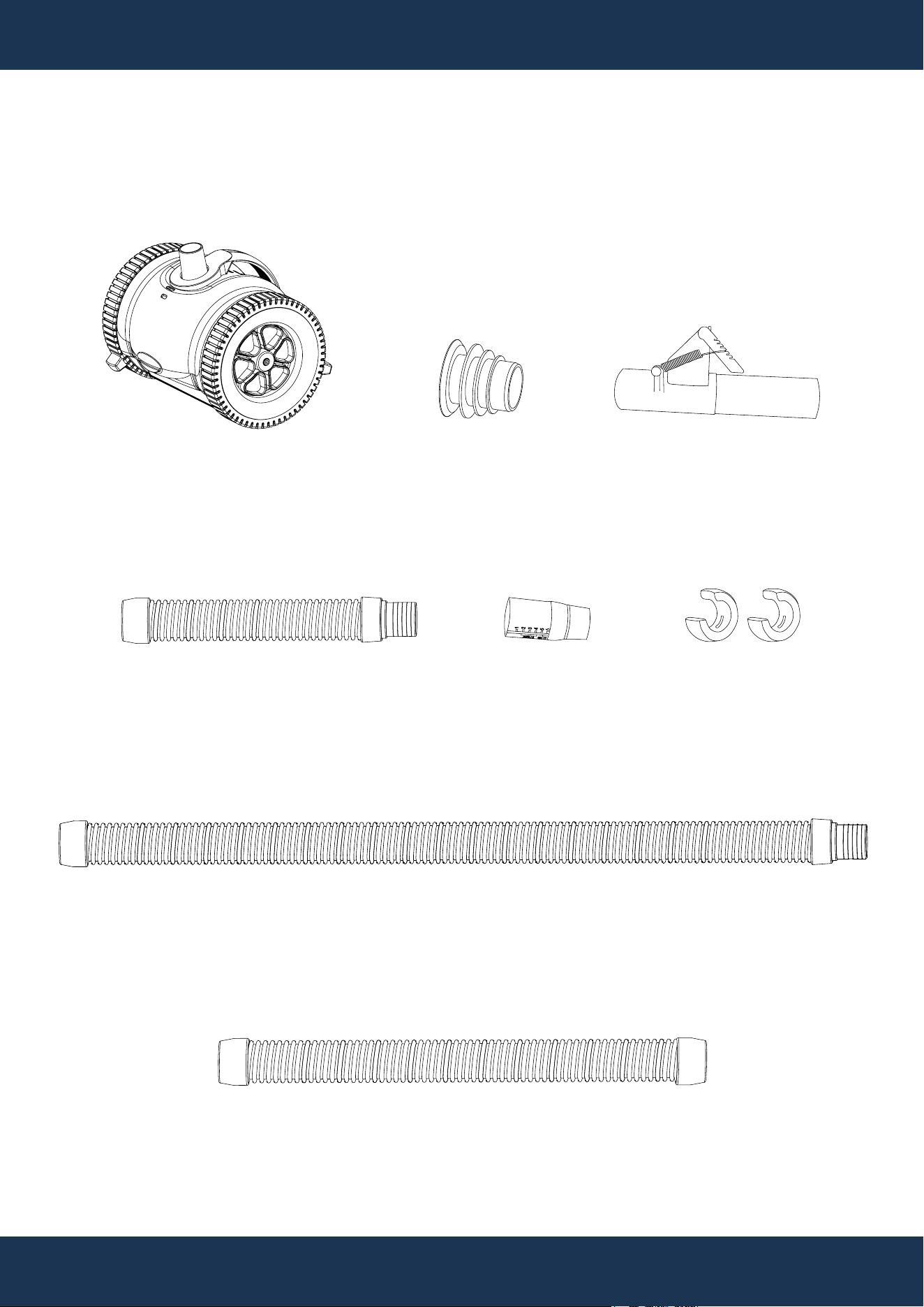
PACKAGE CONTENTS
OVERVIEW (PRODUCT INFORMATION)
PARTS # 7
FLOW CONTROL VALVE
1 PC(S)
PARTS #
1
HEAD CLEANER
1 PC(S)
PARTS #
4
FLOW GAUGE
1 PC(S)
PARTS #
6
CONTROL VALVE ADAPTER
1 SET(S)
PARTS # 5
HOSE FLOAT
2 PC(S)
PARTS #
3
LEADER HOSE
1 PC(S)
PARTS # 8
FEMALE HOSE
1 PC(S)
PARTS #
2
HOSE
14 PC(S)
5
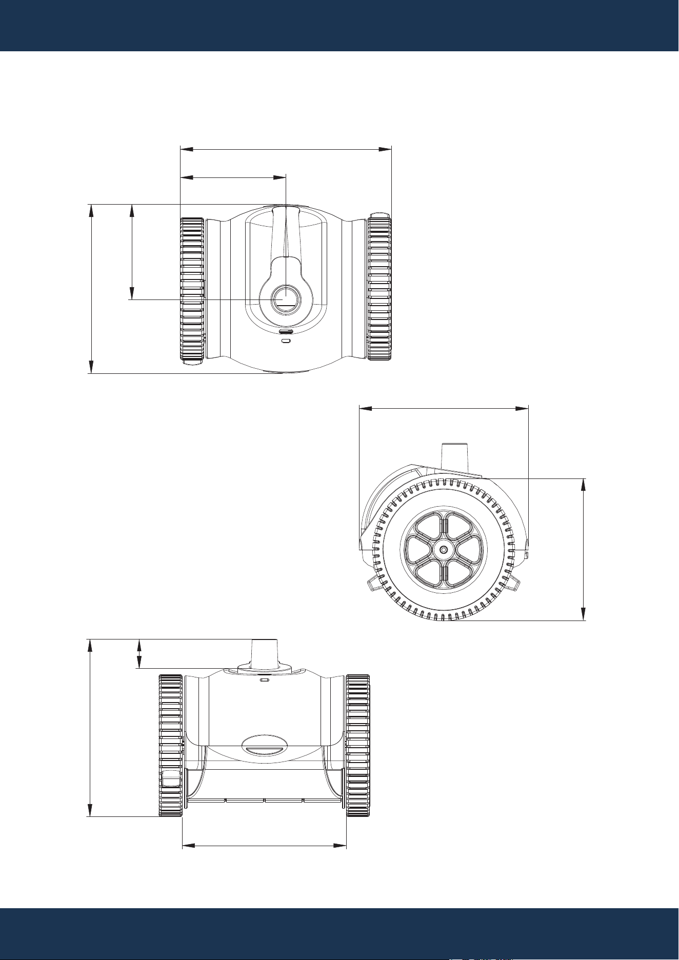
OVERVIEW (PRODUCT INFORMATION)
PRODUCT DIMENSIONS
6.25”
11.75”
5.88”
9”
1.5”
10”
7.75”
9”
9.25”

STEP 1: PRIOR TO INSTALLATION
INSTALLATION
6
Before Installation
• Thoroughly review the operating manual to prevent injury, operational issues, or damage.
• This cleaner is not designed for the initial cleanup after pool construction or at the season's start.
• Inspect pools (vinyl, gunite, plaster, tile, fiberglass) for condition and ensure they are clear of
algae/debris.
• For Vinyl Liner Pools, consultation with a Pool Professional is advised if the liner is damaged or
has underlining obstructions before installation.
• The entire filter system (filter, baskets) must be cleaned to ensure proper cleaner operation.
Preparing the Pool
• Manually vacuum to remove heavy debris and algae.
• Balance the pool water chemicals.
• Brush the pool, allowing debris to settle.
• Clean the pool filter, skimmer, and pump baskets.
• Close the main drain, if applicable.
Usage Tips
• The pool must be in good condition (no broken tiles or tears) for the cleaner's use.
• The cleaner does not clean steps or ladders; these areas require manual cleaning.
• Store the hose straight to prevent coiling.
• Operation of the cleaner under a pool cover is not recommended.
• Removal of the cleaner before chemical treatments is necessary; a waiting period of 4 hours after
shock treatments is recommended.
• Regular cleaning of the filter and inspection of the cleaner for wear are advised.
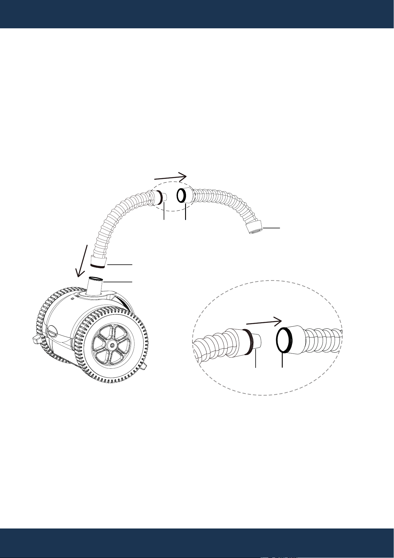
STEP 2: CONNECTING HOSES AND HOSE FLOAT
INSTALLATION
7
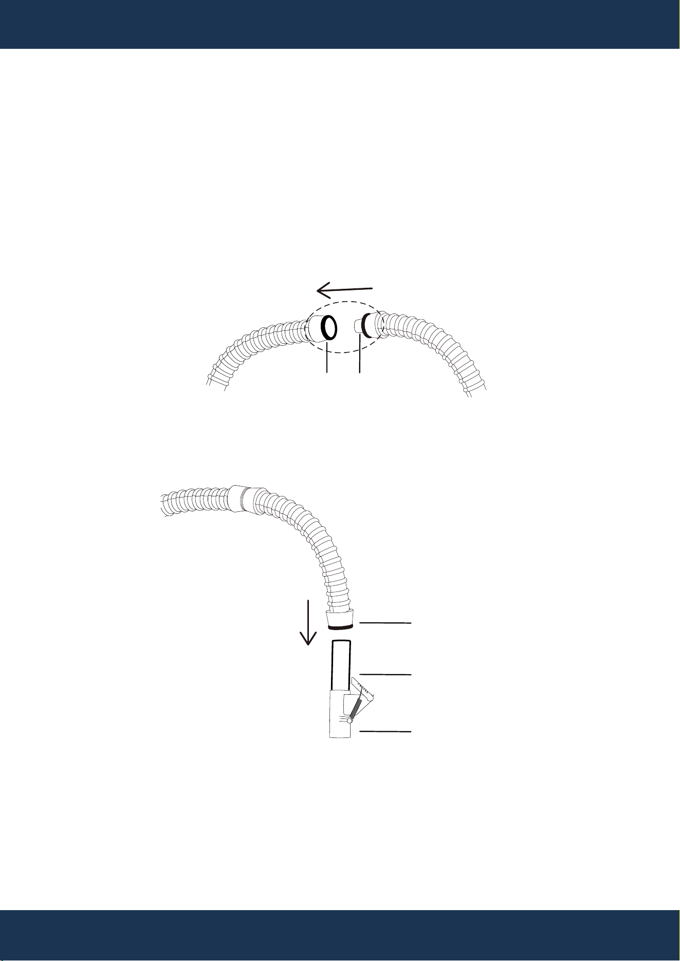
• Attach the female cuff of Parts# 3 to the cleaner's swivel. (Figure 1)
• Insert the male cuff of Parts# 3 into the female cuff of Parts# 8. (Figure 1)
Figure 1
PARTS # 3
PARTS # 1
CLEANER'S SWIVEL
FEMALE CUFF
MALE CUFF
PARTS # 8
FEMALE CUFF
FEMALE CUFF
MALE CUFF
FEMALE CUFF
PARTS # 3 PARTS # 8
INSTALLATION
8
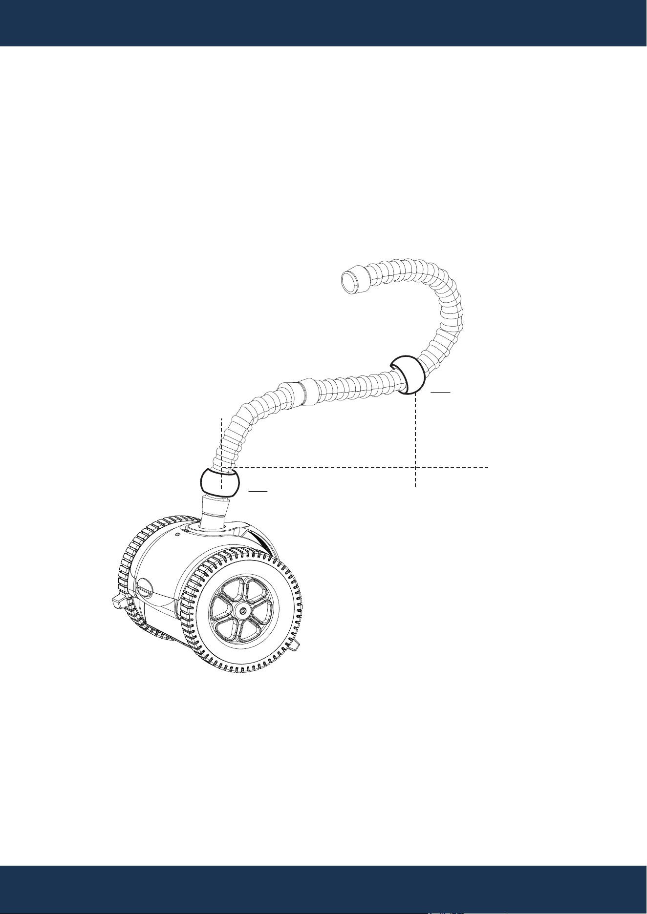
STEP 2: CONNECTING HOSES AND HOSE FLOAT (CONTINUED)
• Place two Parts# 5 on the leader hose at specified distances. (Figure 2)
▪ 1
ST
Parts# 5: Directly at the cleaner's swivel area on Parts# 3.
▪ 2
ND
Parts# 5: 28” from 1
ST
Parts # 5.
Figure 2
PARTS # 3
PARTS # 8
1ST PARTS # 5
2ND PARTS # 5
28” FROM 1ST PARTS # 5
0”
28”
INSTALLATION
9
STEP 2: CONNECTING HOSES AND HOSE FLOAT (CONTINUED)
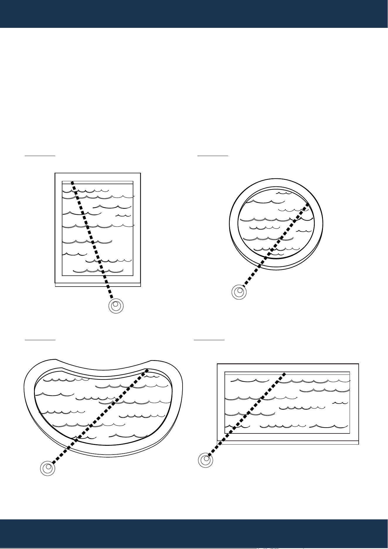
• Connect Parts# 2 as needed from the skimmer or suction port to the farthest pool point, plus one
extra Parts# 2. (Figure 3)
Figure 3 SWIMMIG POOL SHAPE
SKIMMER OR
SUCTION PORT
SKIMMER OR
SUCTION PORT
SKIMMER OR
SUCTION PORT
SKIMMER OR
SUCTION PORT
SHAPE A SHAPE B
SHAPE C SHAPE D
THE FARTHEST
POOL POINT
THE FARTHEST
POOL POINT
THE FARTHEST
POOL POINT
THE FARTHEST
POOL POINT
PARTS # 2
THE FIRST MALE CUFF
END OF PARTS# 2
PARTS # 8
THE FEMALE CUFF
OF PARTS# 8
INSTALLATION
10
STEP 2: CONNECTING HOSES AND HOSE FLOAT (CONTINUED)
• Connect the female cuff of Parts# 8 to the first male cuff end of Parts# 2. (Figure 4)
• Connect the last female cuff end of Parts# 2 to the male cuff end of Parts# 7. (Figure 4)
Figure 4
PARTS # 2
THE LAST FEMALE
CUFF END OF PARTS# 2
PARTS # 7
THE MALE CUFF END
OF PARTS# 7
THE FEMALE CUFF END
OF PARTS# 7
INSTALLATION
11
STEP 3: POOL SKIMMER / SUCTION CONNECTION
Preparation
• Ensure the pool pump is turned off.
• Remove air from the cleaner and hose.
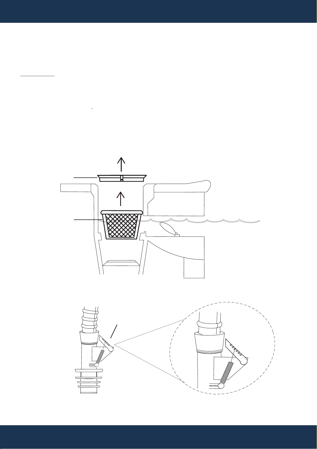
• Remove the skimmer lid and take out the skimmer basket (see Figure 5)
Valve Regulation Adjustment
• Adjust the valve regulator on Parts# 7 for precise calibration (Figure 6)
• Always consult your specific pool cleaner's manual for precise instructions on how to adjust the
regulator valve and what the ideal setting should be.
Figure 5
SKIMMER
BASKET
LID
Figure 6
6
5
4
3
2
1
VALVE REGULATOR
WATERLINE
COPING
WEIR
For Pool Skimmer Connection
6
5
4
3
2
1
VALVE REGULATOR
OF PARTS# 7
PARTS # 7
PARTS # 3
INSTALLATION
12
The Compass Programmable Pool Cleaner is designed with a preprogrammed setting for optimal
performance in most pools. However, its programmability allows customization to accommodate pools
with unique characteristics or larger sizes, ensuring improved coverage and efficiency.
UTILIZING THE PROGRAMMABLE FEATURE
Figure 13
6
5
4
3
2
1
VALVE REGULATOR
OF PARTS# 7
6
5
4
3
2
1
VALVE REGULATOR
OF PARTS# 7
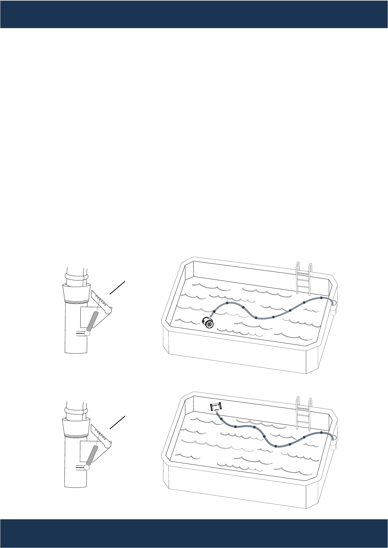
Surface Area Setting
Power Off
• Ensure the pool pump is turned off.
Adjust Valve Regulator
• Adjust the valve regulator on Parts# 7 to match the Ground indication.
• Use levels 1, 2, or 3 as indicated (see Figure 13).
Power Off
• Ensure the pool pump is turned off.
Set Valve Regulator
• Set the valve regulator on Parts# 7 to align with the Climb indication.
• Use levels 5 or 6 as appropriate (see Figure 14).
Adjusting Tire Bumper Height
• For detailed instructions on adjusting the tire bumper height, refer to Chapter: "Maintenance" ->
Section: "Adjusting Tire Bumper Height".
PARTS #
7
Wall Area Setting
Surface Area Setting
Wall Area Setting
Figure 14
PARTS #
7
THE FEMALE CUFF
END OF PARTS# 6
THE MALE CUFF
END OF PARTS# 6
13
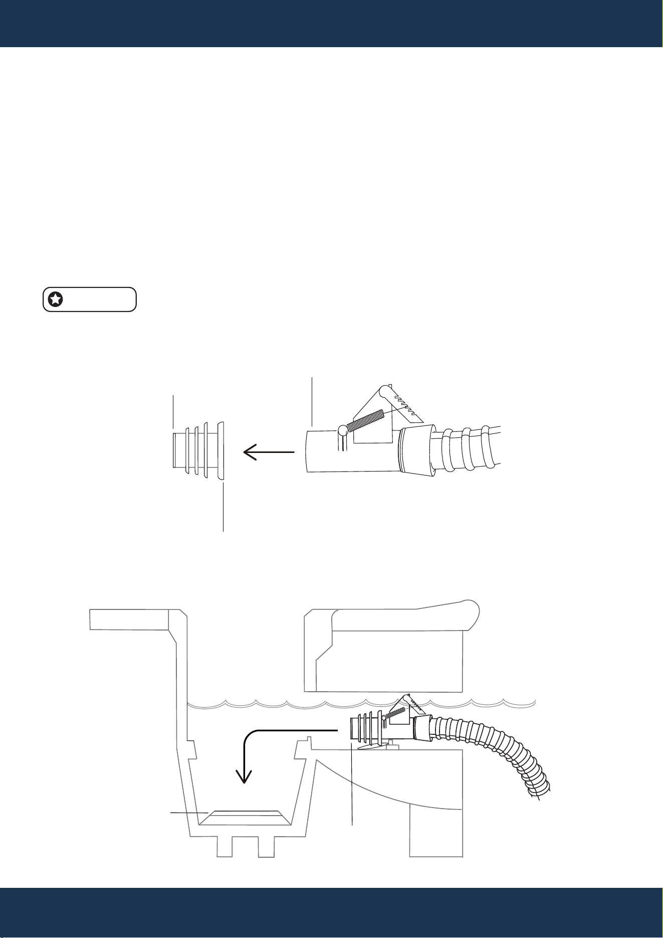
STEP 3: POOL SKIMMER / SUCTION CONNECTION (CONTINUED)
Set-up
• Connect the male cuff end of Parts# 7 to the female cuff end of Parts# 6 (Figure 7).
▪ Use the return jet to fill the vacuum hose with water.
▪ Insert the male cuff end of Parts# 6 from the swimming pool side into the suction port,
ensuring a snug fit. (Figure 8)
Vacuum Activation
▪ Activate the pool pump to initiate automatic vacuuming.
Figure 7
Figure 8
SUCTION PORT
Adjust the flow control valve as needed for optimal performance.
NOTE
THE MALE CUFF
END OF PARTS# 6
SWIMMING POOL
WATERLINE
INSTALLATION
PARTS # 6, 7 and 3
Skimmer Suction Port Connection (Continued)
PARTS #
7
PARTS # 6
THE MALE CUFF
END OF PARTS# 7
PARTS # 3
INSTALLATION
14
Figure 9
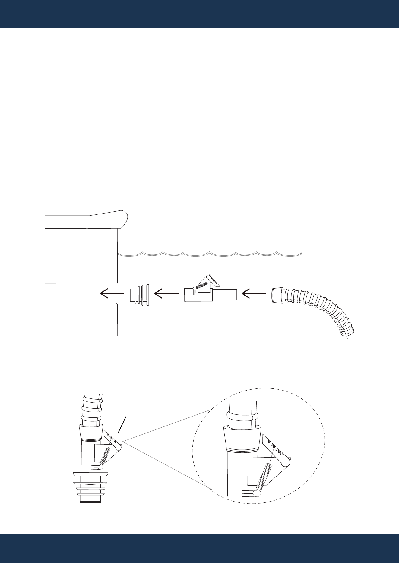
STEP 3: POOL SKIMMER / SUCTION CONNECTION (CONTINUED)
Preparation
• Ensure the pool pump is turned off. Remove air from the cleaner and hose.
• Locate the skimmer wall suction port. (Figure 9)
Valve Regulation Adjustment
• Adjust the valve regulator on Parts# 7 for precise calibration. (Figure 10)
• Always consult your specific pool cleaner's manual for precise instructions on how to adjust the
regulator valve and what the ideal setting should be. (Figure 10).
WATERLINE
COPING
Figure 10
For Dedicated Vacuum Line Connection
PARTS # 6
PARTS # 7
PARTS # 3
6
5
4
3
2
1
VALVE REGULATOR
6
5
4
3
2
1
VALVE REGULATOR
OF PARTS# 7
PARTS # 7
WALL SUCTION
PARTS # 3
INSTALLATION
15
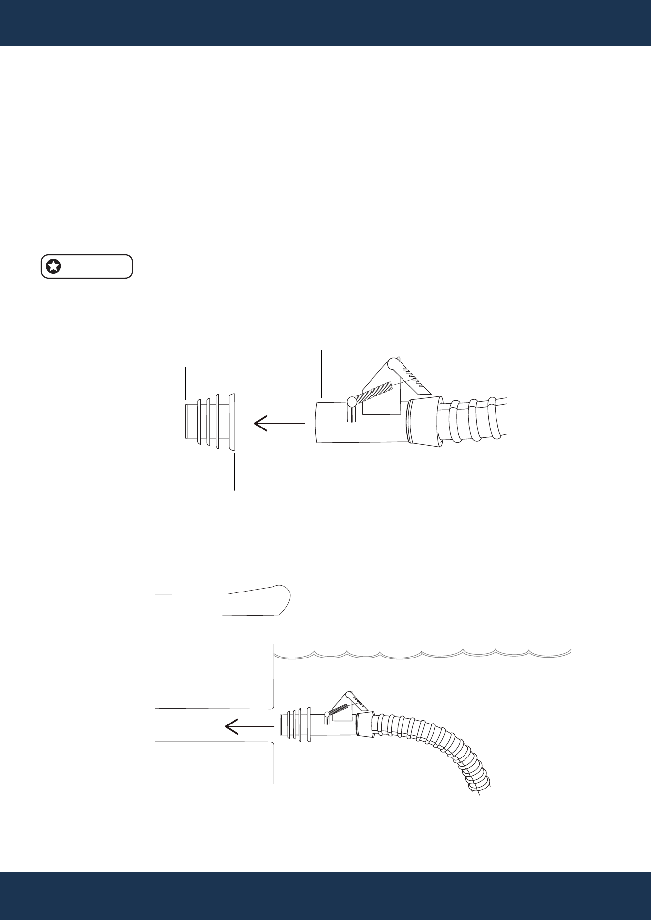
Suction port connection
• Turn off the pool pump and detach Parts# 4 from Parts# 6, replacing it with Parts# 7 (Figure 11).
• Use the return jet to fill the vacuum hose with water.
• Insert the male cuff end of Parts# 6 into the pool's suction port (Figure 12).
Vacuum Activation
• Activate the pool pump to begin automatic vacuuming.
• Adjust the flow control valve as needed for optimal performance.
NOTE
Figure 11
WATERLINE
COPING
Figure 12
STEP 3: POOL SKIMMER / SUCTION CONNECTION (CONTINUED)
For Dedicated Vacuum Line Connection (Continued)
PARTS # 6, 7 and 3
THE FEMALE CUFF
END OF PARTS# 6
THE MALE CUFF
END OF PARTS# 6
PARTS #
7
PARTS # 6
THE MALE CUFF
END OF PARTS# 7
PARTS # 3
WALL SUCTION

16
MAINTENANCE
MAINTENANCE
Hose Storage
• Proper Storage: After removing the hose, keep it straight to prevent coiling, as coiling may hinder
its performance.
Pre-Chemical Treatment Removal
• Before Adding Chemicals: Remove the cleaner and hose from the pool prior to adding chemicals.
• Reinstallation: Wait at least 4 hours after super chlorination before reinstalling the cleaner and
hose to ensure safety and proper operation.
Regular Cleaning
• Maintain the system by cleaning the filter, skimmer basket, and pump basket regularly to ensure
optimal performance.
Wear and Tear Inspection
• Periodically inspect the cleaner for signs of wear or damage.
• Replace any worn components promptly to maintain functionality and efficiency.
ROUTINE MAINTENANCE
Power Down & Detach
• Ensure the pool pump is turned off before beginning. Remove the Pool Cleaner from the water
and disconnect it from the hose.
Perform a Manual Wheel Test
• Attempt to manually rotate the wheels of the cleaner. If the wheels do not move, it indicates a
potential clog inside the cleaner.
To Inspect and Remove Clogs (Figure 13)
▪ Disassemble the Cover: Place the cleaner on a stable surface. Gently press the front and
back buttons to release the cover.
▪ Remove the Cover: Carefully lift and set aside the cleaner's cover.
▪ Detach the Shroud: Insert a screwdriver under the clip securing the Shroud. Twist the
screwdriver gently to detach and remove the Shroud.
▪ Remove Debris: Inspect the gears and turbine for any debris or obstructions.
▪ Clear all debris thoroughly.
▪ Reassembly: Reconstruct the cleaner by reversing the disassembly steps. Ensure all parts
are securely reattached.
UNCLOGGING THE CLEANER
• Set Flow: Set parts# 7’s valve regulator to align with the Climb indication on parts# 4. Refer to
chapter “INSTALLATION” -> section “UTILIZING THE PROGRAMMABLE FEATURE” -> “Wall
Area Setting”.
• Remove Bumper: Detach the bumper from the tire to increase friction and prevent slipping on
walls.
ADJUSTING TIRE BUMPER HEIGHT
MAINTENANCE
17
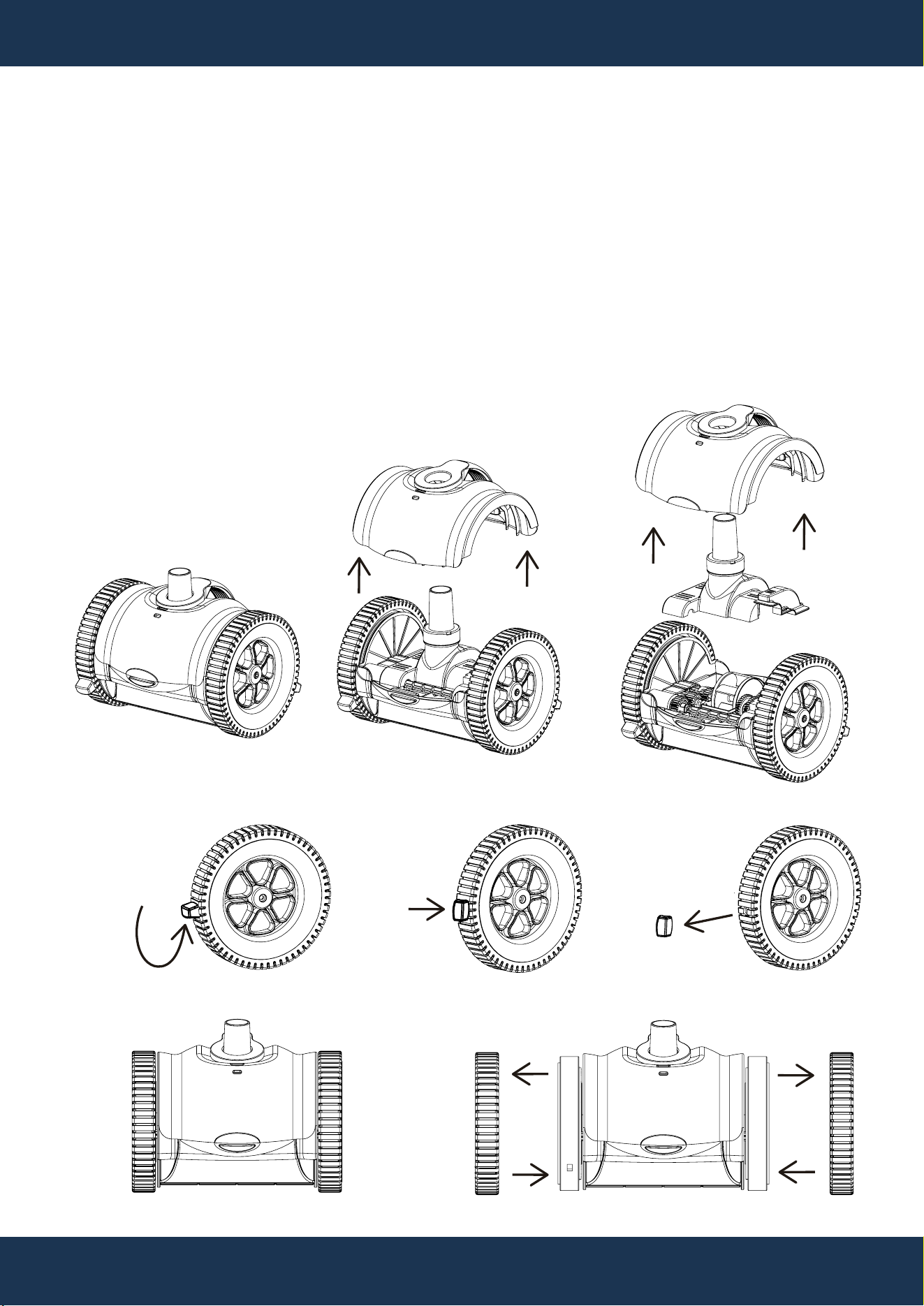
REPLACING TIRES
To Replace Tires: (Figure 15)
• Power Off & Remove: Ensure the pool pump is off and lift the cleaner from the pool.
• Detach Hose: Disconnect the cleaner from the hose.
• Remove Bump: refer to chapter “MAINTENANCE” -> section “ADJUSTING TIRE BUMPER
HEIGHT”.
• Remove Old Tires: On a flat work surface, gently pull the tires away from the hub frame of the
cleaner's wheel until they are completely removed.
• Install New Tires: Fit the new tires onto the wheel hub frame.
• Reassemble Cleaner: Follow the removal steps in reverse order to put the cleaner back together.
Figure 13
Figure 14
Figure 15

TROUBLESHOOTING
18
TROUBLESHOOTING
Cleaner Movement Issues (No Movement or Slow):
• Ensure the main drain is closed.
• Clean the pool filter and empty the pump strainer basket.
• Check for sufficient flow through the Flow Control Valve. For dedicated vacuum lines, adjust
valves at the pool pad for optimal flow.
• Use a flow gauge to measure and adjust the hose flow as needed.
• Inspect inside the cleaner for debris and check for leaks in the pool system, indicated by bubbles.
Cleaner Won't Climb Walls:
• Increase the flow to the cleaner.
• Confirm hose float is correctly positioned as indicated in the manual.
• Check for excessive tire wear which can impair wall climbing capabilities.
• Ensure the meter dial is set for wall climbing and verify correct Leader Hose installation.
Cleaner Coverage Issues (Not Cleaning Entire Pool or Staying in One Area):
• Measure hose flow with a flow gauge to meet requirements.
• Ensure hose length is correct.
• Correctly position the hose float and adjust return line flow to manage cleaner movement.
• Check the hose for leaks.
• Ensure the Flow Control Valve connection is secure and the pump basket lid is fitted correctly,
checking for any damage or missing O-rings.
Cleaner Stays on Main Drain:
• Ensure the main drain is closed and consult a pool professional if needed.
• Consider fitting Tire Bumpers to the cleaner.
• Cleaner Climbs Above Waterline:
• Position the hose float correctly.
• Measure and adjust the hose flow if it's too high.
• Hose and Flow Control Valve Connection Issues:
• Fit a Hose Adapter to the Flow Control Valve for proper connection.
• Cleaner Gets Stuck on Steps or Other Obstacles:
• Reduce suction, check the hose length and consider adding additional hose sections. Monitor
wheel RPM and replace worn Tire Bumpers as necessary.
REPLACEMENT PARTS
19
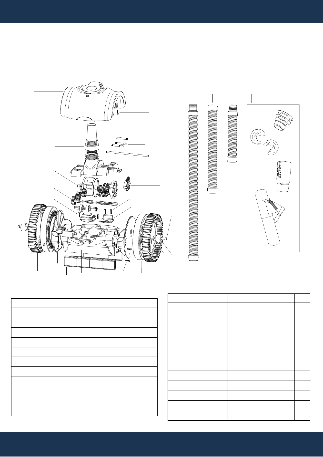
REPLACEMENT PARTS
PARTS DIAGRAM
ITEM
1
2
3
4
5
6
7
8
9
10
11
PART NUMBER
47329601394
47329603052
647329672001
647329673000
647329674000
647329675001
647329676001
647329618817
4732961405
4830712052
47329612001
DESCRIPTION
COVER
HANDLE
GEAR COVER ASSEMBLY
TURBINE ASSEMBLY
GEAR / SHAFT ASSEMBLY
BUTTON ASSEMBLY
WHEEL ASSEMBLY
TIRE KIT
SUPPORTING FEET
BALANCE BLOCK KIT
LEFT WHEEL PANEL
QTY
1
1
1
1
1
1
2
2
2
8
1
ITEM
12
13
14
15
16
17
18
19
20
21
22
23
PART NUMBER
47329613001
47329602052
647329677000
5214026000
5212077000
5212006000
5214028000
5224026000
47325052054
47325053054
48930738054
647327583000
QTY
1
1
1
2
6
2
8
2
14
1
1
1
DESCRIPTION
RIGHT WHEEL PANEL
BASE
SHAFT BASE ASSEMBLY
SCREWS M6*40
SCREWS ST4.2*16-F-H
SCREWS ST4.2*12-F-H
SCREWS ST3.5*13-C-H
SCREWS M4*10
HOSE 0.8M
HOSE 0.8M
HOSE 0.38M
ACCESSORIES KIT
1
2
19
5
4
20
21
6
17
15
7
16
3
2322
5
13
11
10
12
18
9
8
14
7
7

DISCLAIMER
DISCLAIMER
PLEASE READ THE FOLLOWING CAREFULLY
The manufacturer and/or distributor have provided the parts list and assembly diagram in this
manual for reference purposes only. They do not make any representation or warranty to the buyer
that they are qualified to make repairs to the product or replace any parts of the product. In fact, the
manufacturer and/or distributor expressly state that all repairs and parts replacements should be
undertaken by certified and licensed technicians, and not by the buyer.
The buyer assumes all risk and liability arising from their repairs to the original product or
replacement parts or arising from their installation of replacement parts. It is strongly advised that
qualified professionals handle any repairs or replacements to ensure safety and proper functioning
of the product. Improper installation and operation may result in injury, property damage, or voiding
of warranty. The manufacturer and/or distributor shall not be held responsible for any accidents,
damages, or malfunctions resulting from the buyer's installation and operation of the product. It is
essential to follow all safety guidelines and recommendations provided in this manual and to seek
professional assistance if unsure about the installation or operation procedures.
CUSTOMER SERVICE
If you have any questions about ordering our pool pumps and replacement parts or pool products,
please feel free to contact us using the following contact information:
Customer Service and Technical Support
Phone: (909) 628-0880
Email: [email protected]
Hours of Operation: Monday – Friday, 9AM – 4PM (CST)
20
