

ELECTRIC BENCHTOP BUFFER POLISHER TOOL MACHINE
ELECTRIC BENCHTOP BUFFER POLISHER TOOL MACHINE
SAVE THIS MANUAL: KEEP THIS MANUAL FOR SAFETY WARNINGS, PRECAUTIONS, ASSEMBLY,
OPERATING, INSPECTION, MAINTENANCE AND CLEANING PROCEDURES. WRITE THE PRODUCT’S
SERIAL NUMBER ON THE BACK OF THE MANUAL NEAR THE ASSEMBLY DIAGRAM (OR MONTH
AND YEAR OF PURCHASE IF PRODUCT HAS NO NUMBER)
OWNER’S MANUAL AND SAFETY INSTRUCTIONS
ITEM: 45808, 45809, 45810
FOR QUESTIONS PLEASE CALL OUR CUSTOMER SUPPORT: 909.628.0880 MON-FRI 9AM TO 3PM PST
IMPORTANT SAFETY INFORMATION
GENERAL SAFETY WARNINGS
Read all safety warnings and instructions. Failure to follow the warnings and instructions may
reference.
SAFETY
The warnings, precautions, and instructions discussed in this instruction manual cannot cover all possible
conditions and situations that may occur. It must be understood by the operator that common sense and
caution are factors which cannot be built into this product, but must be supplied by the operator. Read
carefully and understand all ASSEMBLY AND OPERATION INSTRUCTIONS before operating. Failure
to follow the safety rules and other basic safety precautions may result in serious personal injury.
1
KEEP GUARDS IN PLACE and in working order.
REMOVE ADJUSTING KEYS AND WRENCHES. Form habit of checking to see that keys and adjusting
wrenches are removed from tool before turning it on.
KEEP WORK AREA CLEAN. Cluttered areas and benches invite accidents.
DON’T USE IN DANGEROUS ENVIRONMENT. Don’t use power tools in damp or wet locations, or
expose them to rain. Keep work area well lighted.
KEEP CHILDREN AWAY. All visitors should be kept safe distance from work area.
MAKE WORKSHOP KID PROOF with padlocks, master switches, or by removing starter keys.
DON’T FORCE TOOL. It will do the job better and safer at the rate for which it was designed.
USE RIGHT TOOL. Don’t force tool or attachment to do a job for which it was not designed.
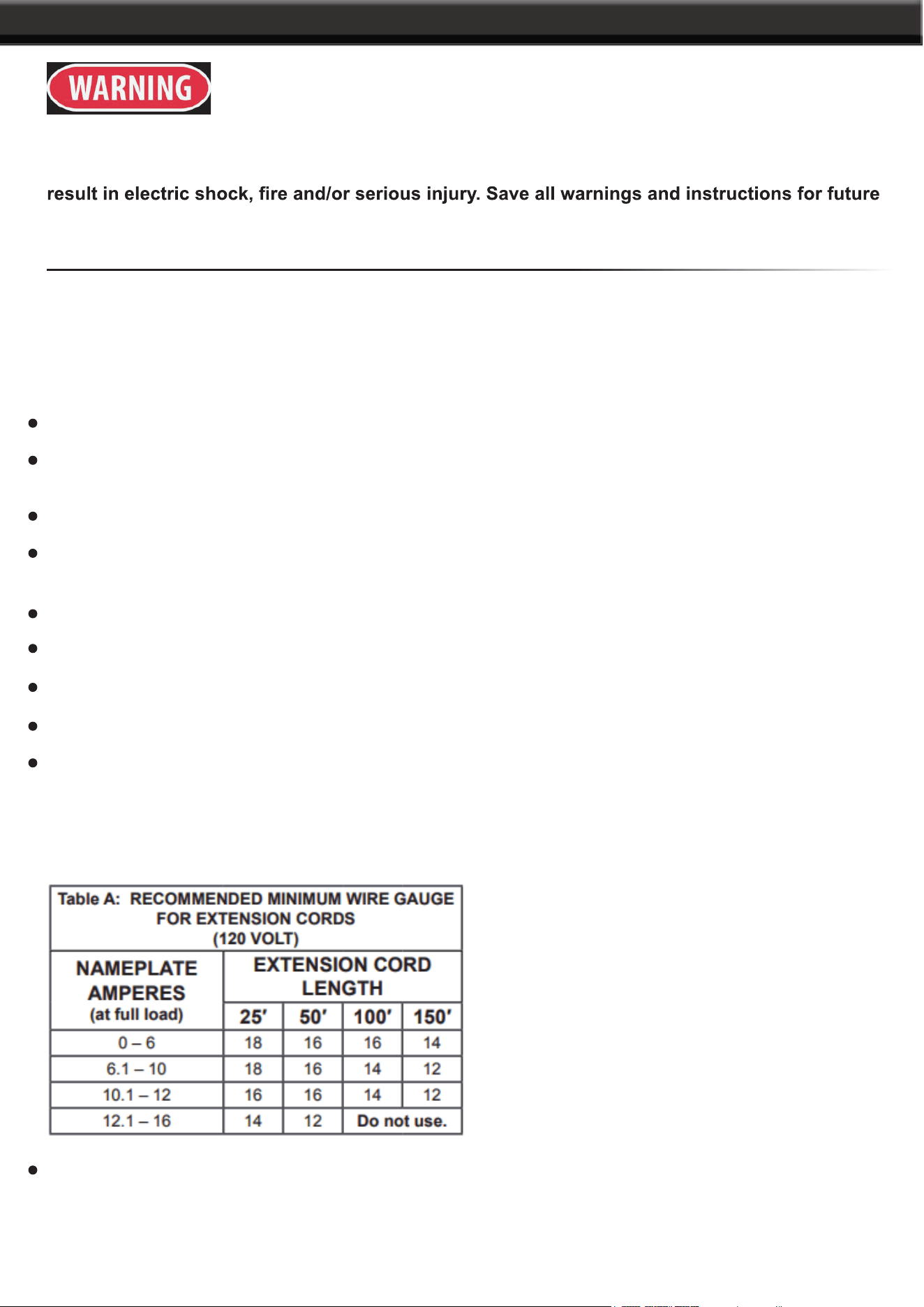
USE PROPER EXTENSION CORD. Make sure your extension cord is in good condition. When using
an extension cord, be sure to use one heavy enough to carry the current your product will draw. An
undersized cord will cause a drop in line voltage resulting in loss of power and overheating. Table A
shows the correct size to use depending on cord length and nameplate ampere rating. If in doubt, use
the next heavier gauge. The smaller the gauge number, the heavier the cord.
WEAR PROPER APPAREL. DO NOT wear loose clothing, gloves, neckties, rings, bracelets, or other
jewellery which may get caught in moving parts. Non-slip footwear is recommended. Wear protective
hair covering to contain long hair.

IMPORTANT SAFETY INFORMATION
2
ALWAYS USE SAFETY GLASSES. Also use face or dust mask if cutting operation is dusty. Everyday
eyeglasses only have impact resistant lenses, they are NOT safety glasses.
SECURE WORK. Use clamps or a vise to hold work when practical. It’s safer than using your hand and
it frees both hands to operate tool.
DON’T OVERREACH. Keep proper footing and balance at all times.
MAINTAIN TOOLS WITH CARE. Keep tools sharp and clean for best and safest performance. Follow
instructions for lubricating and changing accessories.
DISCONNECT TOOLS before servicing; when changing accessories, such as blades, bits, cutters, and
the like.
REDUCE THE RISK OF UNINTENTIONAL STARTING. Make sure switch is in off position before
plugging in.
USE RECOMMENDED ACCESSORIES. Consult the owner’s manual for recommended accessories.
The use of improper accessories may cause risk of injury to persons.
NEVER STAND ON TOOL. Serious injury could occur if the tool is tipped or if the cutting tool is
unintentionally contacted.
CHECK DAMAGED PARTS. Before further use of the tool, a guard or other part that is damaged should
be carefully checked to determine that it will operate properly and perform its intended function – check
for alignment of moving parts, binding of moving parts, breakage of parts, mounting, and any other
conditions that may affect its operation. A guard or other part that is damaged should be properly repaired
or replaced.
DIRECTION OF FEED.
NEVER LEAVE TOOL RUNNING UNATTENDED. TURN POWER OFF.
110-120 VAC GROUNDED TOOLS: TOOLS WITH THREE PRONG PLUGS
1. In the event of a malfunction or breakdown, grounding provides a path of least resistance for electric
grounding conductor and a grounding plug. The plug must be plugged into a matching outlet that is properly
installed and grounded in accordance with all local codes and ordinances.
DO NOT
electrician.
2.
The conductor with insulation having an outer surface that is green with or without yellow stripes is the
DO NOT

3
IMPORTANT SAFETY INFORMATION
3.
grounding instructions are not completely understood, or if in doubt
as to whether the tool is properly grounded.
4. Use only 3-wire extension cords that have 3-prong grounding
plugs and 3-pole receptacles that accept the tool’s plug. Repair or
replace damaged or worn cord immediately
5. This tool is intended for use on a circuit that has an outlet that
looks like the one illustrated above in 125 VAc 3-prong plug and
Outlet. The tool has a grounding plug that looks like the plug
illustrated. above in 125 VAc 3-prong plug and Outlet.
6. The outlet must be properly installed and grounded in accordance with all codes and ordinances.
7. DO NOT use an adapter to connect this tool to a different outlet.
BUFFER SAFETY WARNINGS
1. Wear eye protection.
2.
3. DO NOT buff with side of wheel.
4. DO NOT USE GRINDING WHEELS OR OTHER UNINTENDED ACCESSORIES ON THIS BUFFER.
5. DO NOT wear gloves, necktie, or loose clothing.
6. DO NOT OPERATE WITH ANY GUARD DISABLED, DAMAGED, OR REMOVED.
7. The use of accessories or attachments not recommended by the manufacturer may result in a risk of injury
to persons.
8. When servicing use only identical replacement parts.
9.
10. Stay alert, watch what you are doing and use common sense when operating a power tool. DO NOT use a
while operating power tools may result in serious personal injury.
11. Industrial applications must follow OSHA guidelines.
12. Maintain labels and nameplates on the tool. These carry important safety information. If unreadable or
missing, contact XtremePowerUS for a replacement.
13.
proximity to heart pacemaker could cause pacemaker interference or pacemaker failure.
14. WARNING: Handling the cord on this product will expose you to lead, a chemical known to the State
of California to cause cancer, and birth defects or other reproductive harm. Wash hands after handling.

4
SAVE THESE WARNINGS
APPLICATIONS
15. WARNING: Some dust created by power sanding, sawing, grinding, drilling, and other construction
activities, contains chemicals known [to the State of California] to cause cancer, birth defects or other
reproductive harm. Some examples of these chemicals are:
• Lead from lead-based paints
• Crystalline silica from bricks and cement or other masonry products
• Arsenic and chromium from chemically treated lumber Your risk from these exposures varies, depending
on how often you do this type of work. To reduce your exposure to these chemicals: work in a well ventilated
16. The warnings, precautions, and instructions discussed in this instruction manual cannot cover all possible
conditions and situations that may occur. It must be understood by the operator that common sense and
caution are factors which cannot be built into this product, but must be supplied by the operator.
VIBRATION SAFETY
This tool vibrates during use. Repeated or long-term exposure to vibration may cause temporary or permanent
physical injury, particularly to the hands, arms and shoulders. To reduce the risk of vibration-related injury:
1.
then have regular medical check-ups to ensure medical problems are not being caused or worsened from
use. Pregnant women or people who have impaired blood circulation to the hand, past hand injuries, nervous
system disorders, diabetes, or Raynaud’s Disease should not use this tool. If you feel any medical or
advice as soon as possible.
2. DO NOT
risk of vibration-related injury.
3. Use tools with the lowest vibration when there is a choice between different processes.
4. Include vibration-free periods each day of work. Let the tool do the work.
5. To reduce vibration, maintain the tool as explained in this manual. If any abnormal vibration occurs, stop
use immediately.
5
PARTS and OPERATION
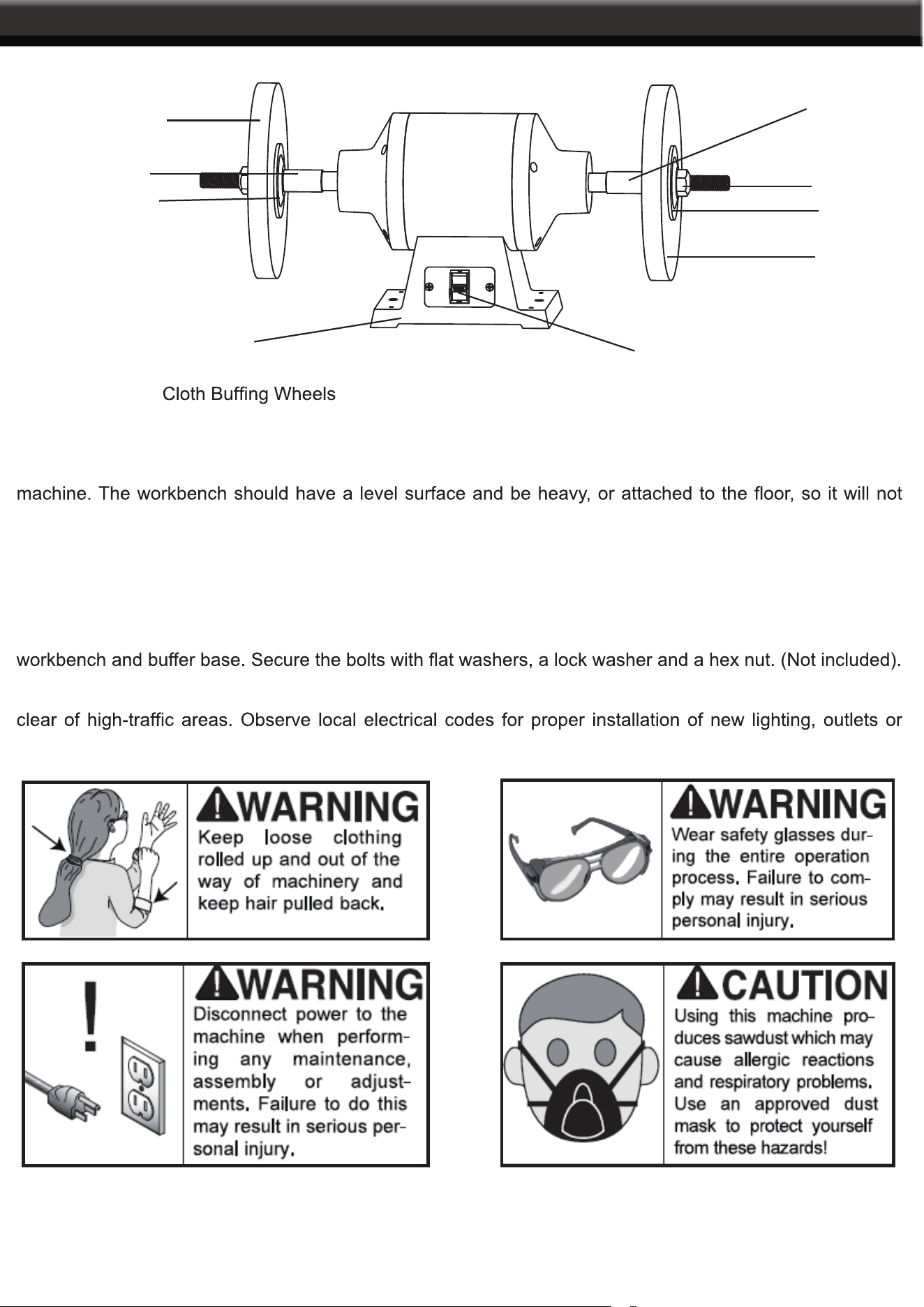
1. Arbor Nut 2. 3. Flange 4. Space 1 5. Space 1 6. Base 7. Power Switch
Make sure the workbench on which you plan to mount the buffer is sturdy enough to hold the weight of the
move during operation. To mount the buffer:
MOUNTING THE BUFFER
1. Pick a spot on the workbench that will allow enough room to move the size of an anticipated workpiece
around the buffer. The operator should make sure they have enough room to move to stand out of the way
of the buffer.
2. Mount the buffer to the workbench with bolts that are long enough to exceed the buffer the thickness of your
3. Mount the buffer in an area with proper lighting and near electrical outlets. Keep power or extension cords
circuits.
The following section is designed to give instructions on the basic operations of this buffer. It is strongly
recommended that the user also read instructional texts and videos to maximize the potential of the machine.
2
3
4
6
7
1
2
3
5
6
OPERATION
Once mounting is complete and adjustments are done, you are ready to test the machine. before testing,
and vise versa on the right hand side.
TEST RUN
Plug in the power and turn on the buffer. Make sure your hand is poised near the switch. The buffer should
run smoothly with little or no vibration or rubbing noises. Strange and unusual noises should be investigated
and corrected before further operation of the machine.
BUFFING AND POLISHING
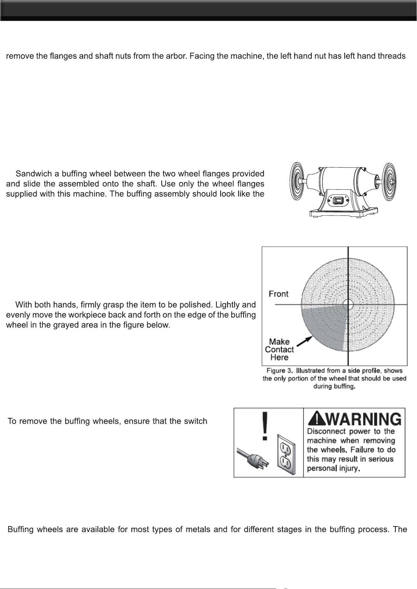
1. Make sure the power cord is unplugged and remove the 5/8” hex nuts at the end of each shaft. facing the
machine, the left-hand shaft has left-handed threads, the right has right-handed threads.
2.
picture beside.
3. Tighten the hex nut while holding the shaft with your other hand. The direction of the threads and motor
rotation ensure that the nuts on both sides will not loosen on their own.
4. Plug the buffer into the power source. Select the appropriate stick
of polishing compound for your application. Turn ON the buffer and
apply the compound to the rotating face of the wheel.
5.
WHEEL REMOVAL
is turned OFF and the power cord is unplugged from
the outlet. Hold the shaft with one while loosening the
nut with a wrench.
BUFFING WHEEL SELECTION
following pictures describe some of the more common wheel types.

7
OPERATION

8
OPERATION
BUFFING COMPOUND SELECTION
Red Rouge - Made for polishing on brass and gold. Provides an excellent shine when used with the loose
Green (Extra Fine)
White - Great for ivory, plastics and resins when used successively with the soft spiral sewn and soft airway
Black
initial rough cut on stainless steel and iron.
Tripoli - A true middle-of-the-road abrasive. Tripoli provides an excellent medium cut for brass, aluminium
and zinc alloy.
Green (Fine)
BUFFING TIPS
removed either chemically or sprayed with water.
in the wheel for a couple seconds. Avoid using too much compound.

OPERATION
9
control.
rough-cut saw blade or a large hacksaw blade will also work as an alternative to a wheel rake. ALWAYS
use light pressure when raking wheels.
DO NOT mix two different compounds on the same wheel. for best results, use a separate wheel for each
compund.
Use an upward stroke with heavy to moderate pressure cutting. Use a downward stroke with light pressure
for polishing. See Fig. 5
LUBRICATION
standard sizes and replacements can be found from our parts department or a bearing supply store.
SPECIFICATIONS
8.5
10
6”& 8” PARTS DIAGRAM

11
6”& 8” PARTS LIST
12
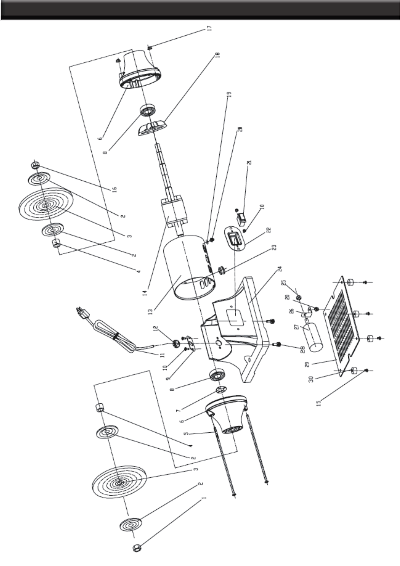
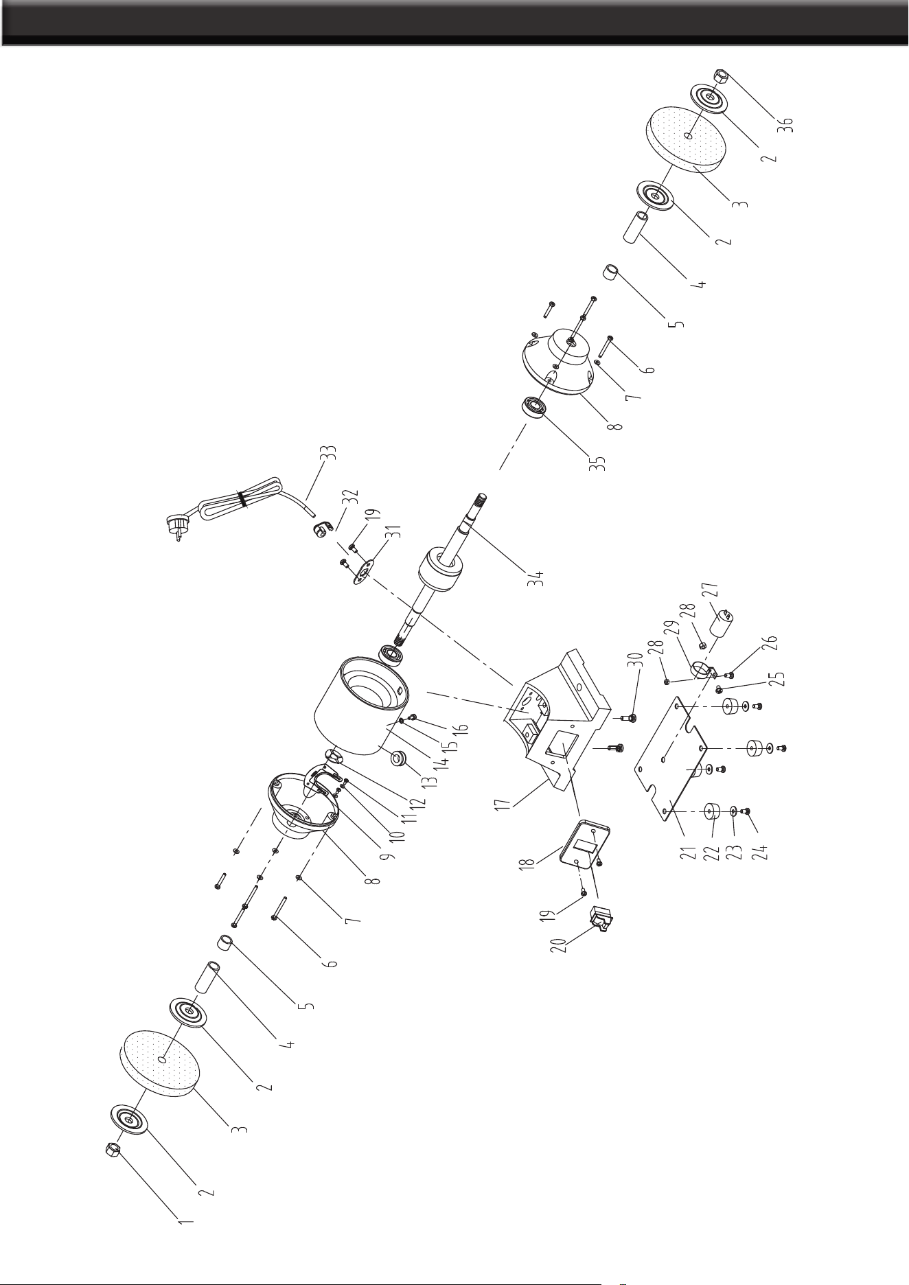
10” PARTS DIAGRAM

13
10” PARTS LIST
NO DESCRIPTION SPEC QTY
1 Nut M20 Left 1
2 Flange 4
3 Buffing wheel 250*20*20 2
4 Shaft bushing(Long) 2
5 Shaft bushing(Short) 2
6 Philips screw M6X25 8
7 Sping washer D6 8
8 End cap 2
9 Centrifugal switch 1
10 Flat washer D4 2
11 Philips screw M4x6 2
12 Wave washer D52 1
13 Lead wire sheath 1
14 Stator 1
15 External teeth lock washer D4 1
16 Phillips screw+Flat washer+Spring washer M4x8 1
17 Base 1
18 Switch plate 1
19 Philips screw M5X8 4
20 Switch 1
21 Bo
tt
om plate 1
22 Rubber feet 4
23 Large flat washer D5 4
24 Philips screw M5x20 4
25 Philips screw M5X16 1
26 Philips screw M5X10 1
27 Capacitor 1
28 Hex nut M5 2
29 Capacitor clip 1
30 Hex bolt+Spring washer M8x25 2
31 Wire clip plate 1
32 Wire clip 1
33 Lead wire plug 1
34 Rotor 1
35 Ball bearing 205 2
36 Nut M20 Right 1


MAINTENANCE
THE MANUFACTURER AND/OR DISTRIBUTOR HAS PROVIDED THE PARTS LIST AND ASSEMBLY
DIAGRAM IN THIS MANUAL AS A REFERENCE TOOL ONLY. NEITHER THE MANUFACTURER OR
DISTRIBUTOR MAKES ANY REPRESENTATION OR WARRANTY OF ANY KIND TO THE BUYER THAT
HE OR SHE IS QUALIFIED TO MAKE ANY REPAIRS TO THE PRODUCT, OR THAT HE OR SHE IS
QUALIFIED TO REPLACE ANY PARTS OF THE PRODUCT. IN FACT, THE MANUFACTURER AND/OR
DISTRIBUTOR EXPRESSLY STATES THAT ALL REPAIRS AND PARTS REPLACEMENTS SHOULD BE
UNDERTAKEN BY CERTIFIED AND LICENSED TECHNICIANS, AND NOT BY THE BUYER. THE BUYER
ASSUMES ALL RISK AND LIABILITY ARISING OUT OF HIS OR HER REPAIRS TO THE ORIGINAL
PRODUCT OR REPLACEMENT PARTS THERETO, OR ARISING OUT OF HIS OR HER INSTALLATION
OF REPLACEMENT PARTS THERETO.
Record Product’s Serial Number Here:
Note: If product has no serial number, record month and year of purchase instead.
Note: Some parts are listed and shown for illustration purposes only and are not available individually
as replacement parts.
PLEASE READ THE FOLLOWING CAREFULLY
PRODUCT MADE IN CHINA
