
I
I� us,
TREEflER
5,,sow GEAR-D,RIVEN 4.
1
6CUFT CEMENT MIXER
ITEM# 67009
O
1
WNER''S MANUAL AND SAFETY INS
,
TRUC.T'IONS
SAVE THIS MANUAL. KETH[S MANUAL FO SAFEWAINGS, PREmNS, ASSEMlY,
OPEON, INSPEON, MA[NTENANCE AND CLNING PROCEDURES. WTE E PRODUCT'S
SEL NUMBER ON BACK OF THE MANUAL OR THE MONTH AND YEA OF PURCHE I
RODU HAS NO SEL NUMBER
FOR QUESTlNIS, PLEASE C.ALL CUSTOMER SE
I
Rl
1
CE: 909
1
•
1
628.0
1
880

GB
SAFETY WARNINGS & INSTRUCTIONS
SYMBOL AFFIXED TO THE MACHINE
Read and understand the owner’s manual and labels affixed to
the mixer. Learn its application and limitations as well as the
specific potential hazards peculiar to it.
Become familiar with the controls before operating this mixer.
Do not operate the mixer while under the influence of drugs,
alcohol, or any medication that could affect your ability to use it
properly.
Do not use this mixer when you are tired or distracted from the
job at hand. Watch what you are doing at all times. Use common
sense.
Make sure there is adequate surrounding workspace.
Keep your work area clean and well lighted. Cluttered areas invite
injuries. Keep area around the mixer clear of obstructions, grease,
oil, trash and other debris which could cause persons fall onto
moving parts.
Only use or operate the mixer on solid, flat, level ground that
is capable to support the weight of the mixer and its load to
prevent the mixer from tipping over.
Do not attempt to move the mixer when it is loaded and/or in
operation.
This mixer is intended for the production of concrete, mortar and
plaster. It is not suitable for the mixing of flammable or explosive
substances. Do not use it in areas where fumes from paint,
solvents or flammable liquids pose a potential hazard.
Check your mixer before turning it on. Check all bolts, nuts, and
screws for tightness before each use, especially those securing
guards and drive mechanisms. Vibration during mixing may cause
these to loosen.
Form a habit of checking to see that all the adjusting tools,
shovels, hand trowels and other tools/equipments are removed
from mixer area before turning it on.
Replace damaged, missing or failed parts before using it.
Warning labels carry important information. Replace any missing
or damaged warning labels.
Do not wear loose clothing, gloves, neckties or jewelry (rings,
wrist watches). They can be caught in moving parts. Protective
electrically non-conductive gloves and non-skid footwear are
recommended when working. Wear protective hair covering to
contain long hair, preventing it from getting caught in machinery.
Wear a face or dust mask if the operation is dusty. Always wear
safety goggles and/or face shields. Everyday eyeglasses have
only impact resistant lenses. They are not safety glasses.
UNDERSTAND YOUR MIXER
STAY ALERT
AVOID DANGEROUS CONDITIONS
INSPECT YOUR MIXER
DRESS PROPERLY
1

Never carry mixer by cord or yank it to disconnect it from socket. Keep cord from heat, oil and sharp edges.
Use only 3-wire extension cords that have 3-prong grounding plugs and 3-pole receptacles that
accept the tool's plug. When using an extension cord, be sure to use one heavy enough to carry the
current your product will draw. A wire gauge size (A.W.G.) of at least 14 is recommended for an
extension cord 50 feet or less in length. A cord exceeding 100 feet is not recommended. If in
doubt, use the next heavier gauge. The smaller the gauge number, the heavier the cord.
Improper use of extension cords may cause inefficient operation of the mixer which can result in
overheating and motor damage. Only extension cords intended for outdoor purpose may be used.
Avoid use of free and inadequately insulated connections. Connections must be made with
protected material suitable for outdoor use. Make sure that any extension cord connections are dry and
safe.
Ensure that the extension cord is carefully laid out avoiding liquids, sharp edges and places where
vehicles might run over it. Avoid allowing the extension cord to be trapped underneath the mixer. Unroll it
fully or it will overheat and could catch fire.
Check that the electric circuit is adequately protected and that it corresponds with the power, voltage and
frequency of the motor. Do not plug or unplug the motor while standing in or around
damp or wet ground. Do not use the mixer in wet or damp areas
or expose it to rain.
Prevent body contact with grounded surfaces: pipes, radiators, ranges, and refrigerator enclosures.
Make sure your fingers do not touch the plug’s metal prongs when plugging or unplugging the mixer.
In the event of a malfunction or breakdown, grounding provides a path of least resistance for electric
current to reduce the risk of electric shock. This tool is equipped with an electric cord having an
equipment-grounding conductor and a grounding plug. The plug must be plugged into a matching
outlet that is properly installed and grounded in accordance with all local codes and ordinances.
Do not modify the plug provided – if it will not fit the outlet, have the proper outlet installed by a qualified
electrician.
Improper connection of the equipment-grounding conductor can result in a risk of electric shock. The
conductor with insulation having an outer surface that is green with or without yellow stripes is
the equipment-grounding conductor. If repair or replacement of the electric cord or plug is
necessary, do not connect the equipment-grounding conductor to a live terminal. Check with a
qualified electrician or service personnel if the
DO NOT ABUSE CORD
EXTENSION CORDS
AVOID ELECTRICAL SHOCK
GROUNDING INSTRUCTIONS
2

SAFETY WARNINGS & INSTRUCTIONS
SYMBOL AFFIXED TO THE MACHINE
Keep unauthorized persons away from the mixer. Do not allow children to handle or
climb on or in the mixer.
Keep proper footing and balance at all times when loading or
unloading the mixer.
Never stand on mixer. Serious injury could occur if the mixer is tipped or if the
moving parts are unintentionally contacted. Do not store anything above or near the
mixer where anyone might stand on the mixer to reach them.
Keep hands out of the way of all moving parts. Do not place any part
of your
body or any tool, like shovel in the drum during operation. When operating, do not
pass hands through the clearance between frame and support leg or the one
between the drum and support leg.
It will do a better and safer job at its design rate. Always work within the rated
capacity.
D
o not start the motor if the drum is fully loaded. Do not turn mixer off while full of
concrete.
Do not use the mixer for a purpose for which it was not intended. The mixer is not to
be towed by any vehicle.
Do not leave mixer until it has come to a complete stop.
Dis
connect from power supply when not in use, before moving, making adjustments,
changing parts, cleaning, or working on the mixer. Consult technical manual before
servicing.
Clean the mixer immediately after use. Keep the mixer clean for best and safest
performance.
W
hen maintaining this mixer, only the manufacturer’s original replacement parts
may be used.
Take left over materials to an authorized collection point or follow the
stipulations
in the country where the mixer is used. Do not discharge into drains, soil or
water.
When not in use, the mixer should be stored in a dry location to inhibit rust. Keep
the mixer away from children and others not qualified to use it.
KEEP VISITORS AND CHILDREN AWAY
DO NOT OVERREACH
AVOID INJURY FROM UNEXPECTED ACCIDENT
DO NOT FORCE TOOL
NEVER LEAVE MIXER RUNNING UNATTENDED
DISCONNECT POWER
MAINTAIN YOUR MIXER WITH CARE
MAINTAIN YOUR MIXER WITH CARE
STORE IDLE EQUIPMENT
groundi
ng instructions are not completely understood, or if in doubt as to whether
the tool is properly grounded.
Repair or replace a damaged or worn cord immediately.
3

4
Safety Warnings & Instructions ………………...………………………………………….…………………………….…...…………………………….…..... 3
Contents of Shipping Container ………………………………………………………………………………………………………………………………….... 7
Assembly Instructions ………………...…………………………………………………………………………………………………………………………………....7
Operation Instructions …………………………………………….……………………………...……………………………………………………………………….. 11
Maintenance Instructions ………………………………………………………………………............……………………………………………………………… 11
Wiring Diagram ………………..………………………………………………………………………………….........………………………………………….............. 12
Parts Schematic ………………………………………………………………………………………………………………………………………………………………... 13
Parts List ……………………………………………………………………………………………………………………………………………………………………………… 14
TABLE OF CONTENTS
SPECIFICATIONS
Model Number
67009
Motor
1/2 HP, 110V/60Hz,
5.3 Amp
Drum Capacity
4.6 Cubic Feet /
135 Liters
Drum Mouth 15.2 inch
Drum Speed 25-27 rpm
Overall Sizes
L 51.6 inch
W 28.4 inch
H 56.3 inch
Weight 92.5 lbs / 42 kg
ASSEMBLY INSTRUCTIONS
M10
×
20
×
4
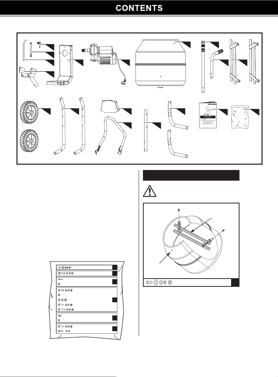
A
Two people assist in assembly recommended.
1
5
4
11 12 13 16
14 15
17 18
6 9 10
7
8
2
3
1. Pivot Pin
2. Bolt M12x205
3. Lock Handle
4. Drum Bracket
5. Swivel Bracket
6. Gearbox and Motor Assembly
7. Drum
8. Straight Handle
9. Bent Handle
10. Mixing Blade
11. Wheel
12. Front Leg
13. Front Leg Reinforcement Plate
14. Angle Support Frame
15. Rear Support Leg
16. Rear Base Leg
17. Operator's Manual
18. Hardware Bag, Including
M10
×
20
×
4
A
M8
×
50
×
2
B
Ø6
×
70
×
4
C
×
4
M10
×
55
×
1
Ø16
×
1
M12
×
1
D
M8
×
45
×
6
M8
×
65
×
1
Ø3
×
1
E
Ø12
×
1
M8
×
50
×
2
F
M8
×
45
×
2
Mixing Blade
Drum
1. Insert the cross headed screws from outside
through the holes in the drum.
2. Slide a rubber washer onto each screws from
inside of the drum, then install the mixing blades
with flat washers, spring washers and nuts as
shown. Tighten securely.
5
M8
×
50
×
2
B
Ø
6
×
70
×
4
C
×
4
M10
×
55
×
1
D
Ø
16
×
1
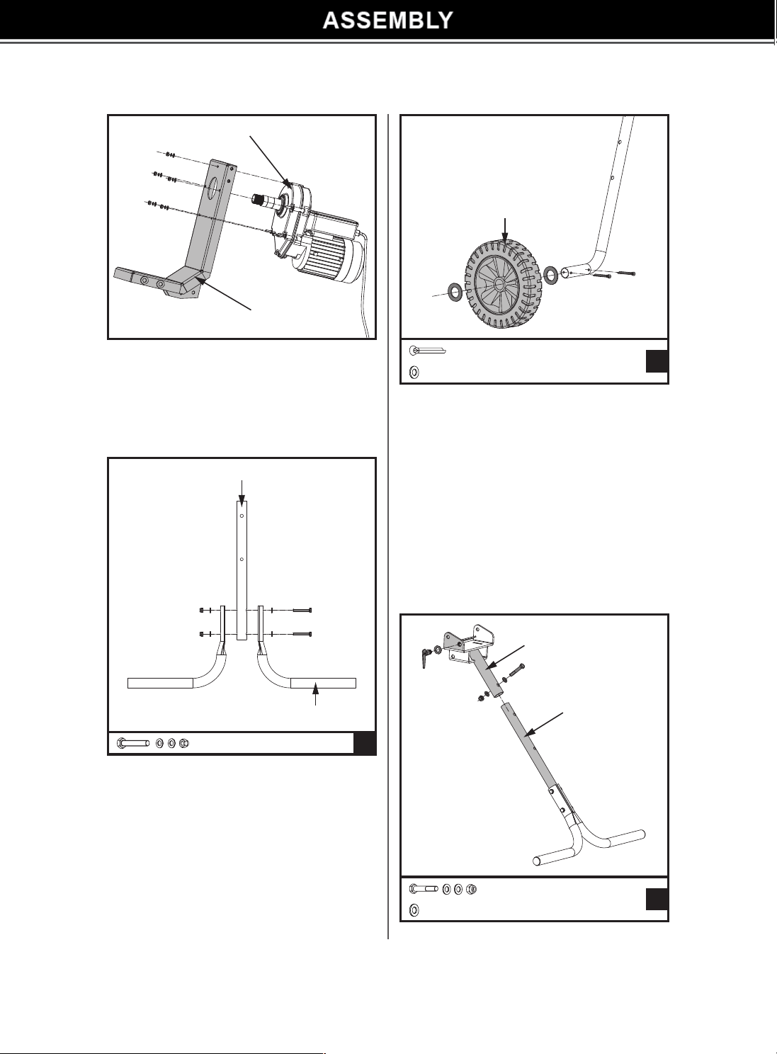
Gearbox and Motor Assembly
Drum Bracket
Rear Support Leg
Rear Base Leg
Wheel
Swivel Bracket
Rear Support Leg
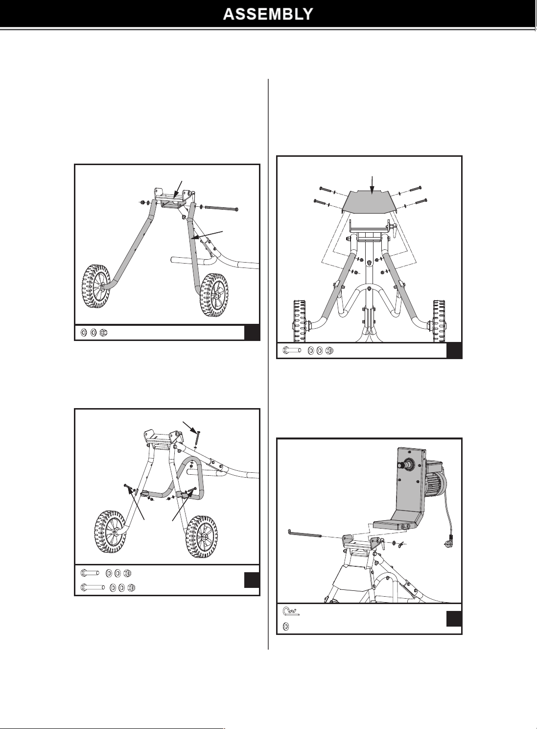
1. Remove the 5sets of nuts, spring washers and
flat washers from the motor gearbox shafts, put
aside for later use.
2. Slide the drum bracket onto the motor shaft
as shown, fix the connection with the removed
hardware kit from 1st step. Tighten securely.
1. Align the holes in the rear support leg with the
holes in the base legs.
2. Insert the two M8x50 bolts with a flat washer
through the holes in the legs.
3. Install a flat washer and nut onto each bolt.
Tighten securely.
1. Locate the two holes in the right front leg.
2. Install a cotter pin into the hole closest to the
leg frame.
3. Slide a washer, a wheel, and a second washer
onto the wheel shaft of the front leg until it
contacts the cotter pin.
4. Install a cotter pin into the second hole.
5. Using pliers, bend the ends of the cotter pins to
secure the wheel in place.
6. Repeat the process on the other side to install
the second wheel.
6
M12
×
1
D
M8
×
45
×
4
D
M8
×
45
×
2
D
M8
×
65
×
1
Ø
3
×
1
E
Ø
12
×
1
Bolt M8x65
Bolt M8x45
Swivel Bracket
Front Leg
Front Leg Reinforcement Plate
1. Thread the lock handle assembly with a Φ16 flat
washer into the swivel bracket.
2. Slide the rear leg into the swivel bracket as
shown. Align the holes, insert the M10x55 bolt
with a flat washer through the holes. Install a
flat washer and lock nut onto the bolt. Tighten
securely.
3. Align the upper holes in the front legs with the
holes in the swivel bracket at each side, insert
the M12x205 bolt with a flat washer through the
holes as shown. Install a flat washer and lock nut
onto the bolt. Tighten securely.
7. Slide the front leg reinforcement plate onto the
front legs as shown.
8. Align the holes in the bracket with the holes
in the legs. Insert a M8x45 bolt with a washer
through the holes. Install a flat washer and lock
nut onto each bolt. Tighten securely.
4. Align the hole in the rear leg with the hole in
the elbow of the angle support frame as shown.
Insert the M8x65 bolt with a flat washer through
the holes. Install a flat washer and lock nut onto
the bolt. Do not tighten the nut at this step.
5. Insert the front legs into the buckles at the open
ends of the angle support frame. Align the holes,
insert the M8x45 bolt with a flat washer through
the holes at each side. Install a flat washer and
lock nut onto each bolt.
6. Securely tighten all the nuts.
7
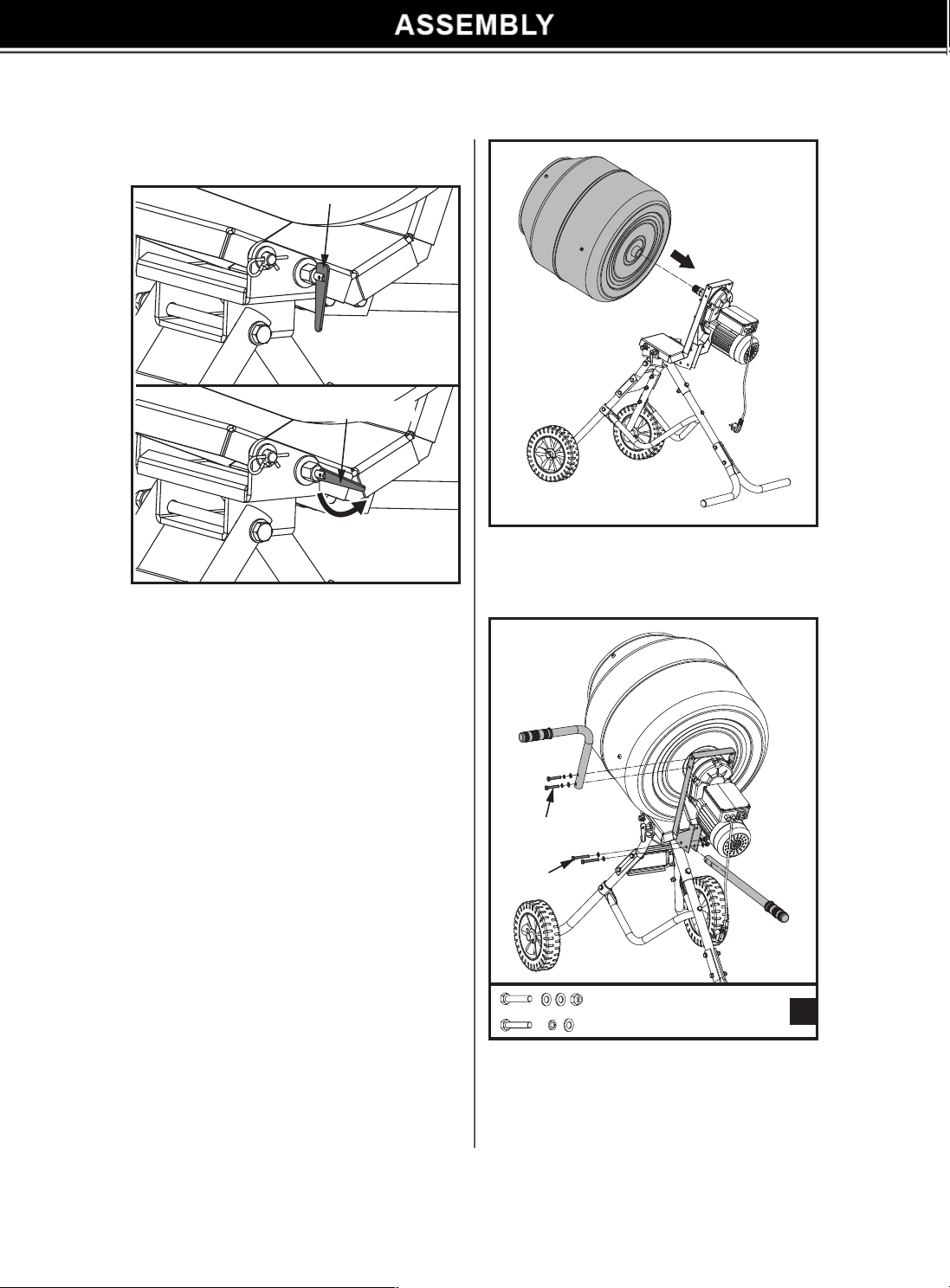
1. Pull the lock handle away from the swivel
bracket and place it in the unlocked position.
2. With the help of a second person, hold the
motor assembly above the swivel bracket.
Lock Position
Unlock Position
3. Align the holes on the motor assembly with the
hole and lock handle on the swivel bracket.
4. Lower the motor assembly into place.
5. Pull the lock handle away from the swivel
bracket and place it in the locked position.
6. Slowly release the lock handle and allow it to
enter the hole in the motor assembly that is
closest to the motor.
7. Insert the pivot pin through the holes in the
swivel bracket and the motor assembly and
secure it with a flat washer and R pin.
Mount the cement mixer drum onto the gear box
shaft. Turn the drum clockwise on the gear box
shaft thread until the shaft is completely located
in the drum.
1. Identify the straight handle and bent handle.
2. Install the straight handle into the drum bracket
underneath the motor. Align the holes in the
handle with the holes in the bracket as shown.
Secure the handle in place with the M8x50
Note: One side of the motor assembly has two
holes and the other has one. The side with
two holes should be on the same side as the
lock handle as shown.
M8
×
50
×
2
F
M8
×
45
×
2
Bolt M8x50
Bolt M8x45
8
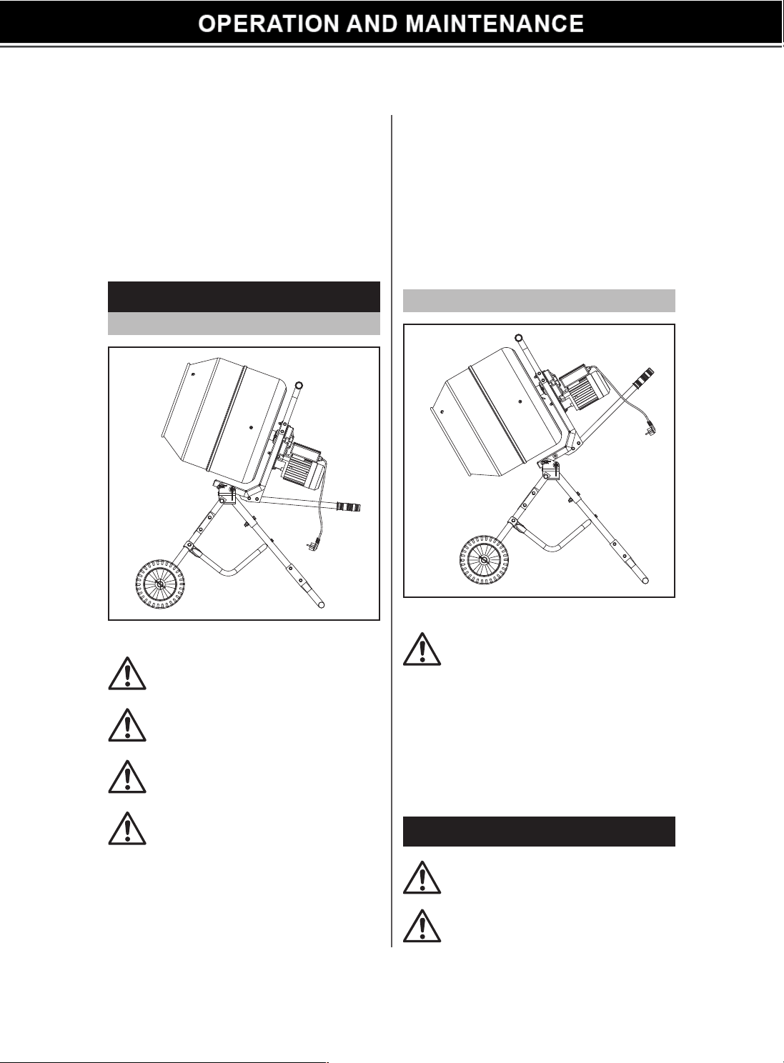
LOADING
EMPTYING
Note: A built-in thermal protecter is arranged in
the motor to prevent it from overheating.
Press the reset button to restore the thermal
protector after the motor cools down.
For best results, proceed as follows:
1. Add the required amount of gravel into the
drum.
2. Add the required amount of cement into the
drum.
3. Add the required amount of sand into the drum.
4. Pour the required amount of water into the
drum.
Check and make sure the lock handle is
in lock position, and head of its shaft is in
the hole of the motor assembly.
Before starting any maintenance or
repairs, stop engine or switch off motor,
and isolate from the main power supply.
On completion of maintenance, check
that the mixer functions correctly and
that all guard are correctly fitted.
Completely unwind the extension cord.
Connect it to the concrete mixer first
before plugging in power supply.
Always start the mixer before loading
the drum. Loading the drum with drum
rotating.
Do not throw material into the mixer to
avoid sticking firmly to the back of the
drum. Trickle it steadily over the ram.
Do not turn mixer off while full of load.
Emptying the drum with drum rotating.
1. Pull the lock handle away from the swivel
bracket and place it in the unlock position to
unlock the beam.
2. Slowly lift the handles up to lower the drum
opening.
3. Once the drum is empty or the job is complete,
raise the drum opening and lock the drum in place.
OPERATION INSTRUCTIONS
MAINTENANCE INSTRUCTIONS
bolts, washers and nuts.
3. Install the bent handle onto upside of the drum
bracket. Align the holes in the handle with
the holes in the bracket as shown. Secure the
handle in place with the M8x45 bolts, spring
washer and flat washer as shown.
Note: following the operator's operation habit, the
bent handle can be installed on either side
of the bracket.
LOADING / MIXING POSITION
UNLOADING / EMPTYING POSITION
9
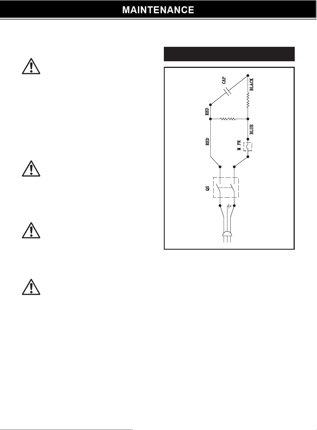
WIRING DIAGRAM
Thoroughly clean the mixer at the end of each
day’s operation. Keep your mixer clean. The
slightest trace of material left in the drum will
harden and attract more each time you use it until
the machine is useless. Dried cement should be
scraped out of the drum. Do not throw bricks into
mixer drum to clean it out. Do not beat on the
drum with a shovel, a hammer or other tools to
break up accumulations of dried cement mix, as
damage to the mixer may result.
Wipe off any external material on the motor.
Do not use petrol, turpentine,lacquer or
paint thinner, dry cleaning fluids or similar
products.
Parts in a circle should only be fitted by a
qualified electrician.
The wiring diagram and parts schematic
in this manual are as reference tools only.
Neither the manufacturer nor distributor
makes any representation or warranty
of any kind to the buyer that he or she is
qualified to make any repairs to the product
or that he or she is qualified to replace
any parts of the product. Only qualified
technicians should repair the mixer. Any
maintenance and repairs carried out, to
any of the electric components must be
undertaken by a qualified electrician.
CLEANING
Never put hands inside the drum with
drum rotating.
10
WIRING DIAGRAM
11

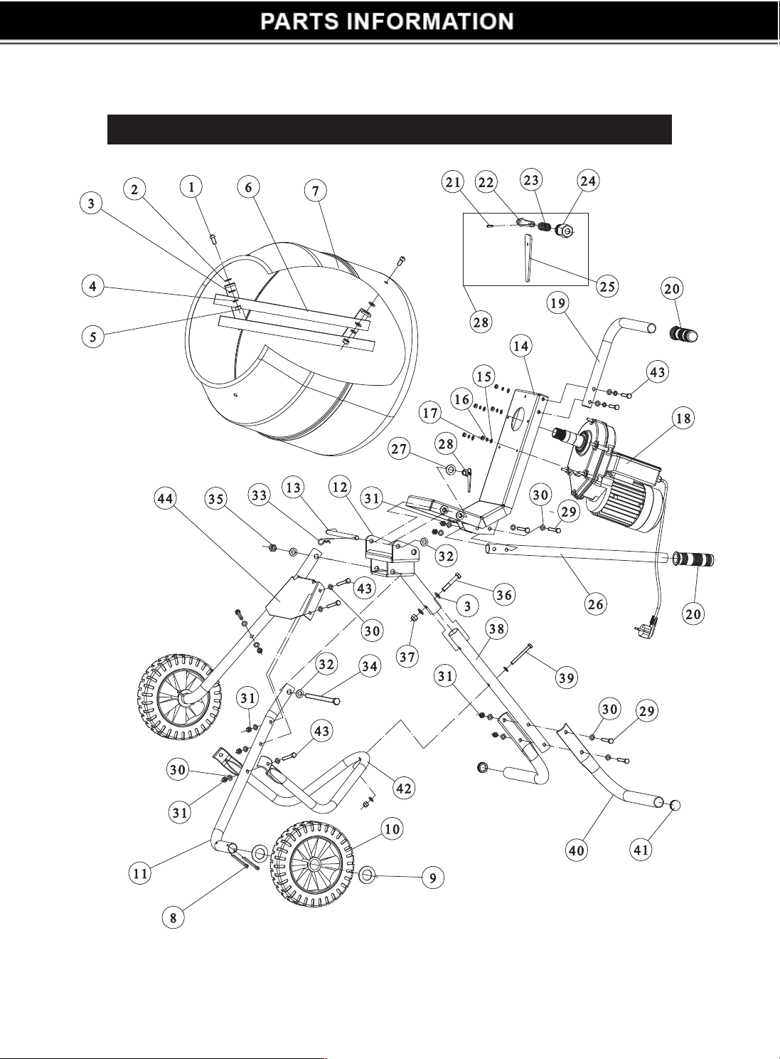
Parts List
No. Description Q'ty
1 Screw M10x20 4
2 Rubber Washer 4
3 Flat Washer 10 6
4 Spring Washer 10 4
5 Nut M10 4
6 Mixing Blade 2
7 Drum 1
8 Cotter Pin Ø6X50 4
9 Washer 4
10 Wheel 2
11 Front Leg 2
12 Swivel Bracket 1
13 Pivot Pin 1
14 Drum Support Bracket 1
15 Flat Washer 6 5
16 Spring Washer 6 5
17 Nut M10 5
18 Gearbox and Motor Assembly 1
19 Bent Handle 1
20 Handle Sleeve 2
21 Spring Pin Ø3x10 1
22 Lock Handle Shaft 1
No. Description Q'ty
23 Spring 1
24 Lock Handle Shaft Sleeve 1
25 Lock Handle 1
26 Straight Handle 1
27 Flat Washer 16 1
28 Lock Handle Assembly 1
29 Bolt M8x50 4
30 Flat Washer 30 24
31 Lock Nut M8 11
32 Flat Washer 12 3
33 R-Pin Ø3 1
34 Bolt M12x205 1
35 Lock Nut M12 1
36 Bolt M10x55 1
37 Lock Nut M10 1
38 Rear Support Frame 1
39 Bolt M8x65 1
40 Rear Base Leg 2
41 Tube Plug 2
42 Angle Support Frame 1
43 Bolt M8x45 8
44 Front Leg Reinforcement Plate 1
12

DISCLAIMER
PLEASE READ THE FOLLOWING CAREFULLY
THE MANUFACTURER AND/OR DISTRIBUTOR HAS PROVIDED THE PARTS LIST AND ASSEMBLY
DIAGRAM IN THIS MANUAL AS A REFERENCE TOOL ONLY. NEITHER THE MANUFACTURER OR
DISTRIBUTOR MAKES ANY REPRESENTATION OR WARRANTY OF ANY KIND TO THE BUYER THAT HE
OR SHE IS QUALIFIED TO MAKE ANY REPAIRS TO THE PRODUCT, OR THAT HE OR SHE IS QUALIFIED
TO REPLACE ANY PARTS OF THE PRODUCT. IN FACT, THE MANUFACRER AND/OR DISTRIBUTOR
EXPRESSLY STATES THAT All REPAIRS AND PARTS REPLACEMENTS SHOULD BE UNDERTAKEN
BY CERTIFIED AND LICENSED TECHNICIANS, AND NOT BY THE BUYER. THE BUYER ASSUMES
All RISK AND LIABILITY ARISING OUT OF HIS OR HER REPAIRS TO THE ORIGINAL PRODUCT OR
REPLACEMENT PARTS THERETO , OR ARISING OUT OF HIS OR HER INSTALLAT
I
ON OF REPLACEMENT
PARTS THERETO
.
Record Product's Serial Number Here: ________________ _
Note: If product has no serial number, record month and year of purchase instead,
Note: Some parts are listed and shown for illustration purposes only and are not available
individually as replacement parts,
llu: mah:rial in this manual is for informational pu1pl�\Cs only. U1e prudutb,l it dsrit"s ,m.• subje.l to ,lwue withuul
prior nutin·, d tu the rnanuhKturc:r ontinuuus Jevi •lopn1t:nt pruuu. Xtrn·Po"
·
erl:S mak,:s no reprc:s.•11laliu11s
or w�1rr.u1ties w
i
th r . pl to thi.s
r
nanual or with rp1 to the prodlll�ls dsaihaed hrin. XITmel'owt'rl:s . hall not he
1i,1bl for any a:nat"s, losses, os or expenss, dircd, indirc:d or iidntal. onquculial or sp:ial, arising out of. or
T1.1ted lo the use of this materi;1I M the prod1Kt. de�rihed hrein.
Questions, issues or missing parts?
Before returning to your retailer, our customer seice team Is here to help.
Call Us: 909.628.0880
�
Email Us: [email protected]
Hours of Operation: 9am • 3pm PST Monday • Friday
MADE IN CHINA
13