
5261-DE
Vacuum Assisted HAMMERVAC™ Dust Extractor
Mar. 2015
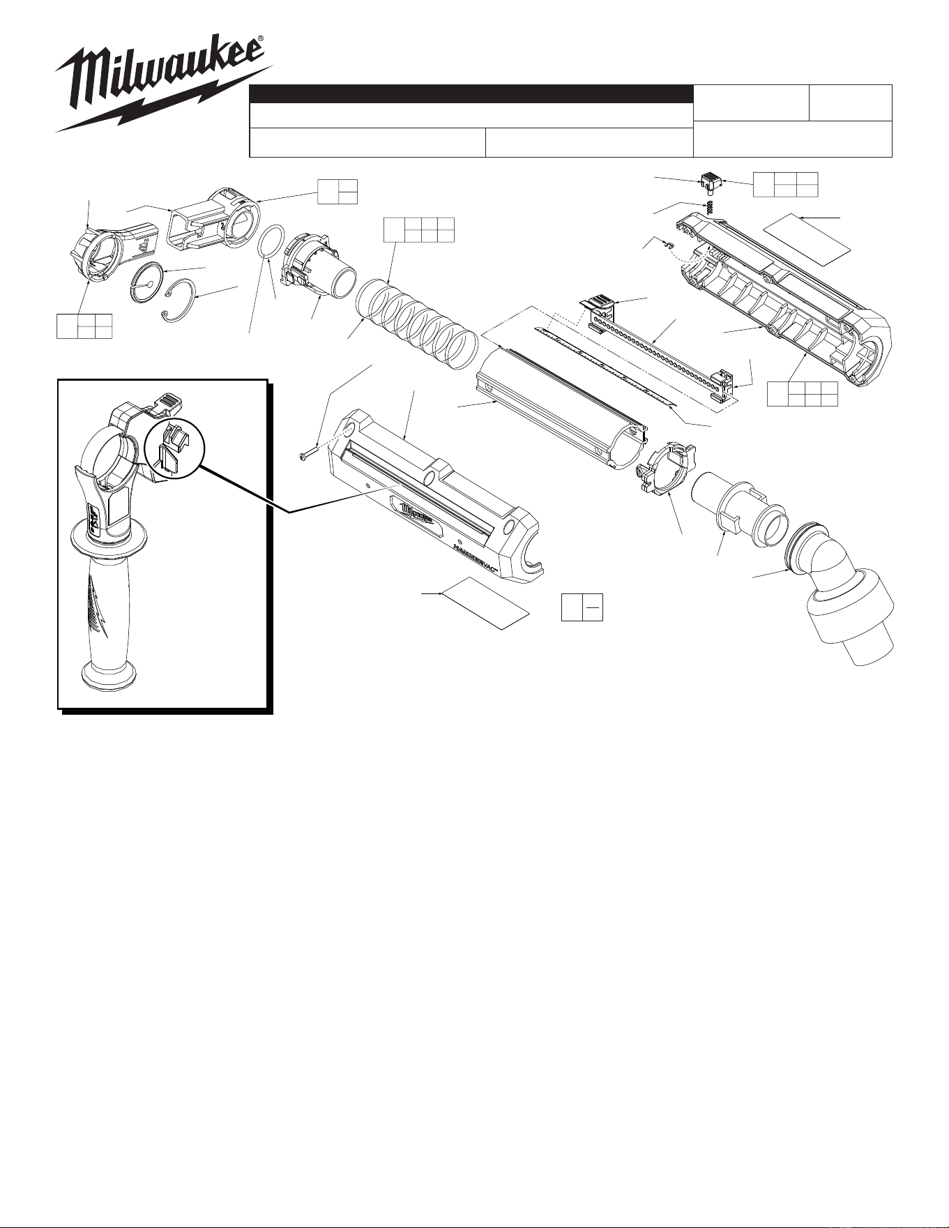
FIG. PART NO. DESCRIPTION OF PART NO. REQ.
1 49-90-2301 Nozzle Top Assy. (Accessory, Pack of 2) (1)
1a 34-60-0995 Retaining Ring (1)
1b 43-31-0475 Hair Brush (Pack of 2) (1)
1c 31-01-2150 Nozzle Top (1)
2 42-20-0900 Nozzle Base Assembly (1)
2a 31-06-0275 Nozzle Base (1)
2b 34-40-0990 O-Ring - Nozzle (1)
3 42-42-1175 Depth Stop Button Assembly (1)
4 42-86-5261
Vacuum Hose Adapter (Accommodates 4 Diameter Sizes)
(1)
5 31-51-0150 Movable Ruler (1)
6 45-76-1051 Extension Tube Assembly (1)
6a 31-12-0710 Tube Cap - Front (1)
6b 45-76-0750 Spring Tube (1)
6c 44-81-0100 Tube Track (1)
6d 42-30-0440 Tube Body (1)
6e 31-12-0720 Tube Cap - Rear (1)
6f 31-05-0741 Dust Outlet (1)
8 14-38-5261 Housing Assembly (1)
8a --------------- Motor Housing Support (1)
8b --------------- Motor Housing Cover (1)
8e 06-82-1080 M3 x 14mm Pan Hd. Plast. T-10 Screw (6)
9 12-20-5269 Service Nameplate (1)
10 10-20-5280 Bi-Lingual Warning Label (1)
11 42-42-1375 Bit Length Adjustment Button Assembly (1)
12 42-42-1300 Clip and Button Assembly (1)
12a 42-42-1180 Rear Release Button (1)
12b 40-50-1820 Spring (1)
12c 44-90-0990 C-Ring (1)
54-05-0015
REVISED BULLETIN
SERVICE PARTS LIST
BULLETIN NO.
WIRING INSTRUCTION
DATE
CATALOG NO.
SPECIFY CATALOG NO. AND SERIAL NO. WHEN ORDERING PARTS
SERIAL
NUMBER
MILWAUKEE ELECTRIC TOOL CORPORATION
13135 W. LISBON RD., BROOKFIELD, WI 53005
Drwg. 1
EXAMPLE:
Component Parts (Small #)
Are Included When Ordering
The Assembly (Large #).
0
00
G64A
Note: Lightly coat O-Ring #2b
with 'L' Grease (49-08-4175) to aid
in installation onto Nozzle Base #2a.
See page 2 for a
complete listing of
side handle and
carrier assemblies
1a 1b
1c
1
2a
2b
2
6a 6b 6c
6d 6e 6f
6
1b
1a
2b
6a
6b
8b
8c
(6x)
6d
6e
6f
4
5
3
6c
8a
9
10
8a 8b 8c
9 10
8
2a
1c
11
12a 12b
12c
12
12a
12b
12c
21a
22a
23a
28
36
25a
26a
27a
29
24
37
38
39
21a 35
37
21
22a 35
38
22
23a 35
39
23
35
(4x)
24 25a
36
25
24 26a
36
26
24 27a
36
27
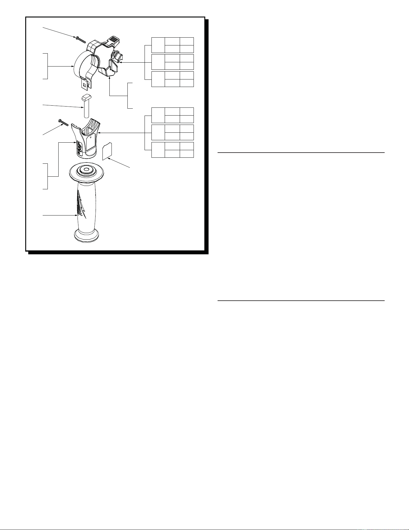
SMALL HANDLE CARRIER ASSEMBLY
FIG. PART NO. DESCRIPTION OF PART NO. REQ.
21 14-48-0200 Handle Carrier Assembly - Small (1)
21a 44-90-1120 Locking Ring - Small (1)
35 05-81-1300 M3 x 10mm Pan Hd. T-10 Screw (4)
37 --------------- Handle Carrier - Small (1)
MEDIUM HANDLE CARRIER ASSEMBLY
FIG. PART NO. DESCRIPTION OF PART NO. REQ.
22 14-48-0250 Handle Carrier Assembly - Medium (1)
22a 44-90-1140 Locking Ring - Medium (1)
35 05-81-1300 M3 x 10mm Pan Hd. T-10 Screw (4)
38 --------------- Handle Carrier - Medium (1)
LARGE HANDLE CARRIER ASSEMBLY
FIG. PART NO. DESCRIPTION OF PART NO. REQ.
23 14-48-0275 Handle Carrier Assembly - Large (1)
23a 44-90-1160 Locking Ring - Large (1)
35 05-81-1300 M3 x 10mm Pan Hd. T-10 Screw (4)
39 --------------- Handle Carrier - Large (1)
SMALL HANDLE HOUSING ASSEMBLY
FIG. PART NO. DESCRIPTION OF PART NO. REQ.
24 10-20-4344 Side Handle Warning Label (1)
25 14-34-1020 Handle Housing Assembly - Small (1)
25a 43-76-0830 Handle Housing - Small (1)
36 05-88-0780 M3 x .75 Pan Hd. Plastite T-10 Screw (1)
MEDIUM HANDLE HOUSING ASSEMBLY
FIG. PART NO. DESCRIPTION OF PART NO. REQ.
24 10-20-4344 Side Handle Warning Label (1)
26 14-34-1040 Handle Housing Assembly - Medium (1)
26a 43-76-0840 Handle Housing - Medium (1)
36 05-88-0780 M3 x .75 Pan Hd. Plastite T-10 Screw (1)
LARGE HANDLE HOUSING ASSEMBLY
FIG. PART NO. DESCRIPTION OF PART NO. REQ.
24 10-20-4344 Side Handle Warning Label (1)
27 14-34-1060 Handle Housing Assembly - Large (1)
27a 43-76-0860 Handle Housing - Large (1)
36 05-88-0780 M3 x .75 Pan Hd. Plastite T-10 Screw (1)
FIG. PART NO. DESCRIPTION OF PART NO. REQ.
28 42-32-0840 T-Bolt (1)
29 31-05-5379 Side Handle (1)