
1c
2a
1b
1a
2b
2c
(2x)
2d
2h
2e(2x)
2j
6
5
2f
2g
2m
2n
11b
11a
2p
2k(4x)
13
3e(8x)
9a
10
14c
3b
3a
3m
(1x)
3f
3h
7a
14b
14a
11c
2q
3j
3g
9b(11x)
3p
12
1a 1b
1c
1
2d 2e
2f
15
2e 2h
2j
16
2p
2q
17
11a 11b
11c
11
14a 14b
14c
14
2a 2b 2c 2d 2e 2f 2g
2h 2j 2k 2m 2n 2p 2q
2
2e 3a 3b 3c 3d 3e 3f 3g
3h 3j 3k 3m 3n 3p 3q
3
3m
(1x)
3m(3x)
3m
7a
7
2e 3a 3c 3e 3k 3m 3p
3q 9a 9b 9c 9d
9
3p
3
9
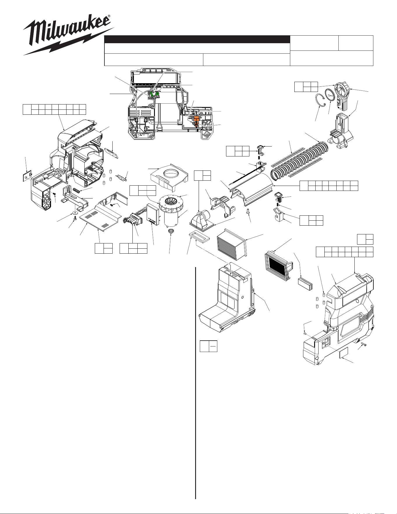
22
2712-DE
M18™ HammerVAC™ Dust Extractor
Aug. 2022
FIG. PART NO. DESCRIPTION OF PART NO. REQ.
1 49-90-2301 Nozzle Top Assy. (Accessory, Pack of 2) 1
1a --------------- Retaining Ring 1
1b --------------- Hair Brush (Pack of 2) 1
1c --------------- Nozzle Top 1
2 45-76-0067 AL Tube Assembly 1
2a 31-12-0082 Nozzle Base 1
2b 45-76-0022 Spring Tube 1
2c 44-81-0040 Detent Plate 2
2d --------------- Depth Release Button 1
2e --------------- Spring 2
2f --------------- Depth Button Cover 1
2g 31-51-0155 Ruler 1
2h --------------- Zero Release Button 1
2j --------------- Zero Button Cover 1
2k 05-78-0135 Flat Hd. ST Phillips Screw 4
2m --------------- AL Tube 1
2n 31-12-1000 Rear Tube Cap 1
2p --------------- Dust Elbow 1
2q 43-44-0077 Gasket 1
3 --------------- Housing Support Assembly (See ref. 22) 1
3a 43-84-2715 Housing Logo Insert 1
3b --------------- Housing Support 1
3c --------------- Screw 2
3d --------------- Finger - Support Side 1
3e 45-30-0003 Rubber Cushion 8
3f 45-88-2160 Washer 1
3g 44-20-0044 Button for Latch 1
3h 05-88-0030 M3 x 8.5mm Pan Hd. ST T-10 Screw 1
3j 40-50-0127 Latch Button Spring 1
3k --------------- Pin 2
3m 05-81-1100 M2.6 x 5mm Phillips Screw 5
3n --------------- Latch 1
3p 42-92-0092 Latch Cover 2
3q --------------- Spring 2
5 42-38-0047 Rubber Bumper 1
6 45-60-0135 Finger Support Plate 1
7 31-15-2715 Wire Cover Plate Assembly 1
7a --------------- Wire Cover Plate 1
9 --------------- Housing Cover Assembly (See ref. 22) 1
9a --------------- Housing Cover 1
9b 06-82-1080 M3.0 x 14mm Pan Hd. T-10 ST Screw 11
9c --------------- Latch 1
9d --------------- Finger - Cover Side 1
10 31-76-0105 Fan Shroud 1
54-05-0040
REVISED BULLETIN
SERVICE PARTS LIST
BULLETIN NO.
WIRING INSTRUCTION
DATE
CATALOG NO.
SPECIFY CATALOG NO. AND SERIAL NO. WHEN ORDERING PARTS
SERIAL
NUMBER
MILWAUKEE TOOL
l
www.milwaukeetool.com
13135 W. LISBON RD., BROOKFIELD, WI 53005
Drwg. 3
EXAMPLE:
Component Parts (Small #)
Are Included When Ordering
The Assembly (Large #).
0
00
G30A
See Page 2
FIG. PART NO. DESCRIPTION OF PART NO. REQ.
11 14-50-2715 Motor/Fan Assembly 1
11a --------------- Motor 1
11b --------------- Fan 1
11c 43-44-1500 Rubber Cap Seal 1
12 49-90-2342 Dust Box (Accessory) 1
13 49-90-2306 Filter (Pack of 3) 1
14 14-20-2718 Electronics Assembly 1
14a --------------- PCBA 1
14b --------------- Terminal Block 1
14c --------------- LED 1
15 42-42-0285 Depth Release Button Assembly 1
16 42-42-0295 Zero Release Button Assembly 1
17 31-05-2000 Dust Elbow Assembly 1
18 12-20-0055 Service Nameplate (See Page Two) 1
19 10-20-0498 Tri-Lingual Warning Label (See Page Two) 1
20 10-20-4352 Dust Box Label (See Page Two) 1
21 10-20-4349 M18 Label (See Page Two) 1
14-52-0045 Service Nozzle for use of 2712-DE
Gen 1 Dust Extractor on 2912-0
1” SDS Plus Hammer (Not Shown) 1
22 31-44-0527 Housing Service Kit 1
#9 Housing Cover
Assembly Shown
3q Spring (2x)
One in each housing halve
3c Washer Screw (2x)
One in each housing halve
3k Latch Pin (2x)
One in each housing halve
9c Latch (Cover)
3n Latch (Support)
2e Spring (2x)
One in each
housing halve
9d Finger (Cover)
3d Finger (Support)
3e Rubber Cushion (8x)
Four in each
housing halve
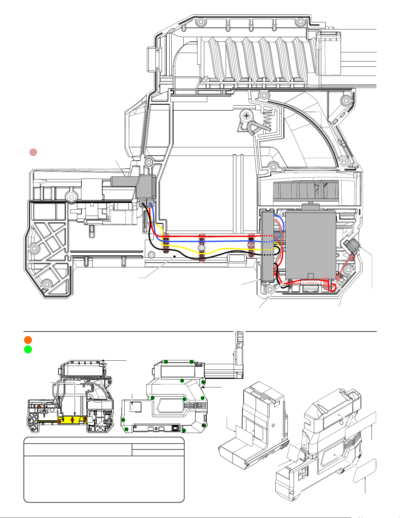
= WIRE TRAPS
or GUIDES
#14b
Terminal Block
#14a
PCBA
#14c
LED
#11
Motor/Fan Assembly
NOTE: Positive terminal of the
motor is marked with a red dot
Illustration shown without
#7 Wire Cover Plate to show
proper wire routing and trapping
AS AN AID TO REASSEMBLY, TAKE NOTICE
OF WIRE ROUTING AND POSITION IN WIRE
GUIDES AND TRAPS WHILE DISMANTLING
TOOL.
BE SURE THAT ALL COMPONENTS OF THE
ELECTRONICS KIT ARE SEATED FIRMLY AND
SQUARELY IN THE HOUSING RECESSES.
AVOID PINCHED WIRES, BE SURE THAT ALL
WIRES AND SLEEVES ARE PRESSED
COMPLETELY DOWN IN WIRE GUIDES AND
TRAPS.
PRIOR TO INSTALLING THE HOUSING
COVER ONTO THE HOUSING SUPPORT,
BE SURE THAT THERE ARE NO
INTERFERENCES.
WIRING DIAGRAM
7a
Wire Cover
Plate
3b
Housing
Support
3p
Latch
Cover
9a
Housing
Cover
= 05-81-1100 Screw, Qty. 5
= 06-82-1080 Screw, Qty. 11
3m
9b
SCREW TORQUE SPECIFICATIONS
SEAT TORQUE
FIG. PART NO. WHERE USED (KG/CM) (IN/LBS)
2k 05-78-0135 Aluminum Tube #2m 5-10 4-9
3c --------------- Finger Cover #9d and
Finger Support #3d 3-7 3-6
3h 05-88-0030 Button for Latch #3g 3-7 3-6
3m 05-81-1100 Wire Cover Plate #7a &
Latch Covers #3p (2x) 3-7 3-6
9b 06-82-1080 Housing Cover #9a 5-10 4-9
20
21
18
19