Operator’s Manual
www. mechmaxx.com
WARRANTY


MAX performance,MAX Value,MAX Support that’s
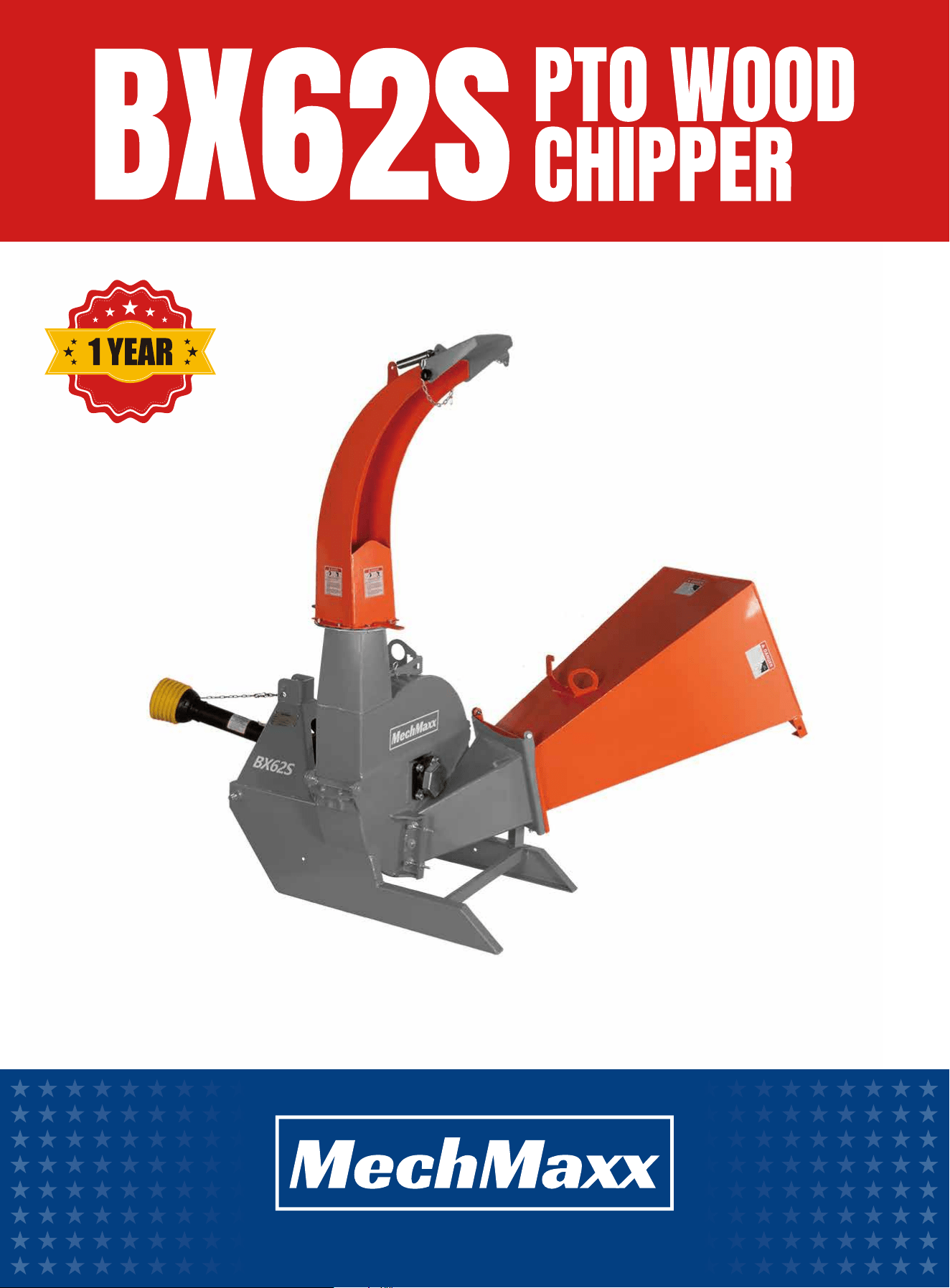
PTO Wood Chipper
Enhanced design features come standard
Engineered for the best user experience
Quality metal parts are used instead of plastic
A robust warranty supports all products
Budget-friendly prices make it practical
TABLE OF CONTENTS
TABLE OF CONTENTS
SPECIFICATIONS
SAFETY SIGNS
SAFETY
1
2
BLADE AND BREAKER MAINTENANCE
13
ROTOR BLADES MAINTENANCE
13
LEDGER BLADES MAINTENANCE
14
BOLT TORQUEBOLT TORQUE
14
ENGLISH TORQUE SPECIFICATIONS
14
METRIC TORQUE SPECIFICATIONS
15
YOUR SAFETY
GENERAL SAFETY
EQUIPMENT SAFETY GUIDELINES
4
4
4
SAFETY TRAINING
5
SAFETY SIGNS
5
PREPARATION
6
MAINTENANCE SAFETY
6
TRANSPORT SAFETY
6
TO THE NEW OPERATOR OR OWNER
6
OPERATION
MACHINE COMPONENTS
MACHINE BREAK-IN
3
4
8
8
8
8
PRE-OPERATION CHECKLIST
MACHINE SET-UP
8
9
DRIVELINE DIMENSION
MOUNTING AND UNHOOKING TRACTOR
9
10
CHIPPING OPERATION
11
UNPLUGGING
SEVERE PLUG
11
11
OPERATION
13
MAINTENANCE
16
PARTS DIAGRAM
17
PARTS LIST
Your new PTO Wood Chipper offers quality construction,
and is easy and safe to operate. With proper use and
care, it is designed to give you many years of depend-
able service.
Prepare to experience the durability to take on any job
with the ease, portability, and convenience of your new
PTO Wood Chipper !
1
www. mechmaxx.com
TABLE OF CONTENTS

SPECIFICATIONS
2
www. mechmaxx.com
SPECIFICATIONS
Tractor Power
Model
30-75HP
BX62S
Max. Throughput Capacity 6 in
Infeed Opening
6.5*10 in
lnfeed Chute Opening
25*25 in
Rotor Diameter
Discharge Chute Rotation
Feeding Opening
30 in
360 Degrees
Gravity Feed
Rotor Thickness 0.2 in
Rotor Weight 190 lbs
Number Of Blades 4+1
Blade (Tines) Material 4CrW2Si
PTO Shaft RPM 540 RPM
Flywheel Speed 540 RPM
Drive Type PTO
Driveline Shaft Length
3-Point Hitch
Dimensions (L x Wx H)
Finsh
Warranty
Net Weight
Gross Weight
CAT 1
58x 38x 50 in
Powder Coat Paint Galvanized Steel
1 year
705 lbs
772 lbs
T6-LF-35.5 in with shear bolt; 35.5 in-47 in【05B-LF-900】
3
www. mechmaxx.com
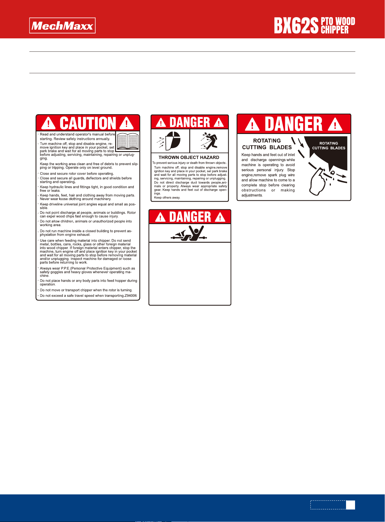
SAFETY SIGNS
The rating plate on your machine may show symbols. These represent important information about the product or instruc-
tions on its use.
SAFETY SIGNS
ROTATING DRIVELINE HAZARD
KEEP AWAY
To prevent serious injury or death from
rotating driveline:
• Keep all guards in place when operating.
• Operate only at 540 RPM.
• Keep hands, feet, hair and clothing away
from moving parts.
• Keep U-joint angles equal and small as
possible.
• Do not exceed driveline manufacturers
recommended operating length.

4
www. mechmaxx.com
IMPORTANT SAFETY INFORMATION
SAFETY
YOU are responsible for the SAFE operation and mainte-
nance of your Tractor Wood Chipper. YOU must ensure
that you and anyone else who is going to use, maintain or
work around the Tractor Wood Chipper be familiar with the
using and maintenance procedures and related SAFETY
information contained in this manual. This manual will
take you step-by-step through your working day and alerts
you to all good safety practices that should be used while
using the Tractor Wood Chipper.
Remember, YOU are the key to safety. Good safety
practices not only protect you but also the people around
you. Make these practices a working part of your safety
program. Be certain that EVERYONE using this equipment
is familiar with the recommended using and maintenance
procedures and follows all the safety precautions. Most
accidents can be prevented. Do not risk injury or death by
ignoring good safety practices.
1. Tractor Wood Chipper owners must give operating
instructions to operators or employees before allowing
them to operate the machine, and at least annually there-
after.
2. The most important safety device on this equipment is
a SAFE operator. It is the operator’s responsibility to read
and understand ALL Safety and Operating instructions in
the manual and to follow these. Most accidents can be
avoided.
3. A person who has not read and understood all using and
safety instructions is not qualified to use the machine. An
untrained operator exposes himself and bystanders to
possible serious injury or death.
4. Do not modify the equipment in any way. Unauthorized
modification may impair the function and/or safety and
could affect the life of the equipment.
5. Think SAFETY! Work SAFELY!
1. Read and understand the Operator’s Manual and all
safety signs before using, maintaining, adjusting, or
cleaning the Tractor Wood Chipper.
2. Have a first-aid kit available for use should the need
arise and know how to use it.
3. Have a fire extinguisher available for use should the
need arise and know how to use it.
4. Do not allow riders.
5. Wear appropriate protective gear. This list includes but
is not limited to:
- A hard hat
- Protective shoes with slip resistant soles
- Heavy gloves
- Wet weather gear
- Hearing Protection
6. Install and secure all guards before starting.
7. Wear suitable ear protection for prolonged exposure to
excessive noise.
8. Turn machine off, stop and disable engine, remove
ignition key and place in your pocket, set park brake and
wait for all moving parts to stop before servicing, adjust-
ing, repairing, or unplugging.
9. Clear the area of people, especially small children,
before using the unit.
10. Review safety related items annually with all person-
nel who will operating or maintaining the Tractor Wood
Chipper.
1. Safety of the operator and bystanders is one of the
main concerns in designing and developing equipment.
However, every year many accidents occur which could
have been avoided by a few seconds of thought and a
more careful approach to handling equipment. You, the
operator, can avoid many accidents by observing the
following precautions in this section. To avoid personal
injury or death, study the following precautions and insist
those working with you, or for you to follow them.
YOUR SAFETY
EQUIPMENT SAFETY GUIDELINES
GENERAL SAFETY

5
www. mechmaxx.com
SAFETY
1. Always keep safety signs clean and legible.
2. Replace safety signs that are missing or have become
illegible.
3. Replaced parts that displayed a safety sign should also
display the current sign.
4. Safety signs have a part number in the lower right hand
corner. Use this part number when ordering replacement
parts.
5. Safety signs are available from your authorized Distrib-
utor or Dealer Parts Department or the factory.
1. Safety is a primary concern in the design and manufac-
ture of our products. Unfortunately, our efforts to provide
safe equipment can be wiped out by a single careless act
of an operator or bystander.
2. In addition to the design and configuration of equip-
ment, hazard control and accident prevention are depen-
dent upon the awareness, concern, prudence, and proper
training of personnel involved in the operation, transport,
maintenance, and storage of this equipment.
3. It has been said, "The best safety feature is an
informed, careful operator." We ask you to be that kind of
an operator. It is the operator's responsibility to read and
understand ALL Safety and Using instructions in the
manual and to follow these. Accidents can be avoided.
4. If this machine is used by any person other than
yourself, or is loaned or rented, it is the machine owner's
responsibility to make certain that the operator, prior to
using:
a. Reads and understands the operator's manuals.
b. Is instructed in safe and proper use.
5. Know your controls and how to stop the Tractor and
machine quickly in an emergency. Read this manual and
the one provided with Tractor.
6. Train all new personnel and review instructions
frequently with existing workers. Be certain only a proper-
ly trained and physically able person will use the machin-
ery. A person who has not read and understood all using
and safety instructions is not qualified to use the
machine. An untrained operator exposes himself and
bystanders to possible serious injury or death. If the elder-
ly is assisting with the work, their physical limitations
need to be recognized and accommodated.
2. In order to provide a better view, certain photographs or
illustrations in this manual may show an assembly with a
safety shield removed. However, equipment should never
be used in this condition. Keep all shields in place. If
shield removal becomes necessary for repairs, replace
the shield prior to use.
3. Replace any safety sign or instruction sign that is not
readable or is missing. Location of such safety signs is
indicated in this manual.
4. Never use alcoholic beverages or drugs which can
hinder alertness or coordination while using this equip-
ment. Consult your doctor about using this machine while
taking prescription medications.
5. Under no circumstances should young children be
allowed to work with this equipment. Do not allow
persons to use or assemble this unit until they have read
this manual and have developed a thorough understanding
of the safety precautions and of how it works. Review the
safety instructions with all users annually.
6. This equipment is dangerous to children and persons
unfamiliar with its operation. The operator should be a
responsible, properly trained and physically able person
familiar with machinery and trained in this equipment's
operations. If the elderly are assisting with work, their
physical limitations need to be recognized and accommo-
dated.
7. Never exceed the limits of a piece of machinery.
8. If its ability to do a job, or to do so safely, is in question
- DON'T TRY IT.
9. Do not modify the equipment in any way. Unauthorized
modification may result in serious injury or death and may
impair the function and life of the equipment.
10. In addition to the design and configuration of this
implement, including Safety Signs and Safety Equipment,
hazard control and accident prevention are dependent
upon the awareness, concern, prudence, and proper train-
ing of personnel involved in the operation, transport, main-
tenance, and storage of the machine. Refer also to Safety
Messages and operation instruction in each of the appro-
priate sections of the Tractor and machine manuals. Pay
close attention to the Safety Signs affixed to the Tractor
and the machine.
SAFETY TRAINING
SAFETY SIGNS

6
www. mechmaxx.com
SAFETY
1. Never use the machine until you have read and
completely understand this manual, the Tractor Opera-
tor's Manual and each of the Safety Messages found on
the safety signs on the Tractor and machine.
2. Personal protection equipment including hard hat,
safety glasses, safety shoes, and gloves are recommend-
ed during assembly, installation, operation, adjustment,
maintaining, repairing, removal, cleaning, or moving the
unit. Do not allow long hair, loose fitting clothing or jewel-
ry to be around equipment.
3. PROLONGED EXPOSURE TO LOUD NOISE MAY CAUSE
PERMANENT HEARING LOSS! Power equipment with or
without equipment attached can often be noisy enough to
cause permanent, partial hearing loss. We recommend
that you wear hearing protection on a full-time basis if the
noise in the Operator's position exceeds 80 db. Noise
over 85 db on a long-term basis can cause severe hearing
loss. Noise over 90 db adjacent to the Operator over a
long-term basis may cause permanent, total hearing loss.
NOTE: Hearing loss from loud noise (from tractors, chain
saws, radios, and other such sources close to the ear) is
cumulative over a lifetime without hope of natural recov-
ery.
4. Clear working area of stones, branches or hidden
obstacles that might be hooked or snagged, causing
injury or damage.
5. Use only in daylight or good artificial light.
6. Be sure machine is properly mounted, adjusted and in
good operating condition.
7. Ensure that all safety shielding, and safety signs are
properly installed and in good condition.
1. Good maintenance is your responsibility. Poor mainte-
nance is an invitation to trouble.
2. Follow good shop practices.
a) Keep service area clean and dry.
b) Be sure electrical outlets and tools are properly ground-
ed.
c) Use adequate light for the job at hand.
3. Make sure there is plenty of ventilation. Never operate
the engine of the towing vehicle in a closed building. The
exhaust fumes may cause asphyxiation.
4. Before working on this machine, shut off the engine,
set the brake, and turn fuel valve off.
5. Never work under equipment unless it is blocked
securely.
6. Always use personal protection devices such as eye,
hand and hearing protectors, when performing any service
or maintenance work. Use heavy or leather gloves when
handling blades.
7. Where replacement parts are necessary for periodic
maintenance and servicing, genuine factory replacement
parts must be used to restore your equipment to original
specifications. The manufacturer will not be responsible
for injuries or damages caused by use of unapproved parts
and/or accessories.
8. A fire extinguisher and first aid kit should be kept
readily accessible while performing maintenance on this
equipment.
9. Periodically tighten all bolts, nuts and screws and
check that all electrical and fuel connections are properly
secured to ensure unit is in a safe condition.
10. When completing a maintenance or service function,
make sure all safety shields and devices are installed
before placing unit in service
1. Comply with state and local laws governing safety and
transporting of machinery on public roads.
2. Check that all the lights, reflectors and other lighting
requirements are installed and in good working condition.
3. Do not exceed a safe travel speed. Slow down for rough
terrain and cornering.
4. Do not drink and drive.
5. Be a safe and courteous driver. Always yield to oncom-
ing traffic in all situations, including narrow bridges, inter-
sections, etc. Watch for traffic when operating near or
crossing roadways.
Follow all safety instructions exactly. Safety is every-
one's business. By following recommended procedures, a
safe working environment is provided for the operator,
bystanders, and the area around the worksite. Untrained
operators are not qualified to operate the machine.
PREPARATION
MAINTENANCE SAFETY
TRANSPORT SAFETY
TO THE NEW OPERATOR OR OWNER

7
www. mechmaxx.com
SAFETY
Many features incorporated into this machine are the
result of suggestions made by customers like you. Read
this manual carefully to learn how to use the chipper
safely and how to set it to provide maximum field efficien-
cy. By following the using instructions in conjunction
with a good maintenance program, your tractor Wood
Chipper will provide many years of trouble- free service.
8
www. mechmaxx.com
OPERATION
OPERATION
The 3 Point Hitch Wood Chippers are designed to chip or
chop scrap lumber, small trees, brush, limbs and other
wood debris. The chipped material is fine enough to be
composted or used in a variety of ways.
It is the responsibility of the owner or operator to read
this manual and to train all other operators before they
start working with the machine. Follow all safety instruc-
tions exactly. Safety is everyone's business.
By following recommended procedures, a safe working
environment is provided for the operator, bystanders, and
the area around the worksite. Untrained operators are not
qualified to use the machine.
The Tractor Mounted Wood Chipper is a rotor with blades
for chipping wood. A hinged feed hopper moves the wood
material into the rotor. Each rotor is designed with 4
blades and a twig-breaker to generate the small pieces of
wood.A stationary knife at the rear of the rotor housing is
placed by the moving knives to shear, chip or chop the
material. The tractor provides rotational power through
its hydraulic system into the hydraulic motor on the rotor
shaft. This drive system is contained in the front frame.
Although there are no operational restrictions on the
Wood Chipper when used for the first time, it is recom-
mended that the following mechanical items be checked:
After operating for 1 hour:
1. Torque all fasteners and hardware.
2. Check condition of rotor bearings.
3. Check the condition and clearance of the twig-breaker,
rotor and stationary blades. Adjust or replace as required.
4. Check for entangled material. Remove all entangled
material before resuming work.
5. Lubricate all grease fittings.
After operating for 10 hours:
1. Repeat steps 1 through 5 listed above. (After operating
for 1 hour)
2. Go to the normal servicing and maintenance schedule
as defined in the Maintenance Section.
Efficient and safe operation of the Tractor Mounted Wood
Chipper requires that each operator reads and under-
stands the using procedures and all related safety
precautions outlined in this section. A pre-operation
checklist is provided for the operator. It is important for
both the personal safety and maintaining good mechani-
cal condition that this checklist is followed. Before
operating the Wood Chipper and each time thereafter, the
following areas should be checked off:
1. Lubricate the machine per the schedule outline in the
Maintenance Section.
2. Check the rotor, blades, and twig-breaker. Remove any
twine, wire or other material that has become entangled.
3. Check the condition and clearance of the twig- breaker,
rotor, and stationary blades. Adjust or replace as required.
4. Check that all bearings turn freely. Replace any that are
rough or seized.
5. Make sure that all guards and shields are in place,
secured and functioning as designed.
6. Check the condition of the curtain in the feed hopper. It
must be in good condition to prevent chips from flying out.
OPERATION
PRE-OPERATION CHECKLIST
MACHINE COMPONENTS
MACHINE BREAK-IN
9
www. mechmaxx.com
OPERATION
Follow this procedure to prepare and setup the machine
at the work site:
1. Use the Tractor to position the Wood Chipper at the
work site.
IMPORTANT
Position the machine so the prevailing wind/breeze
blows the exhaust gases/fumes away from the opera-
tor's station.
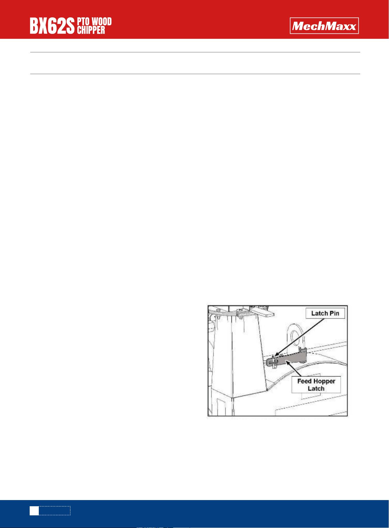
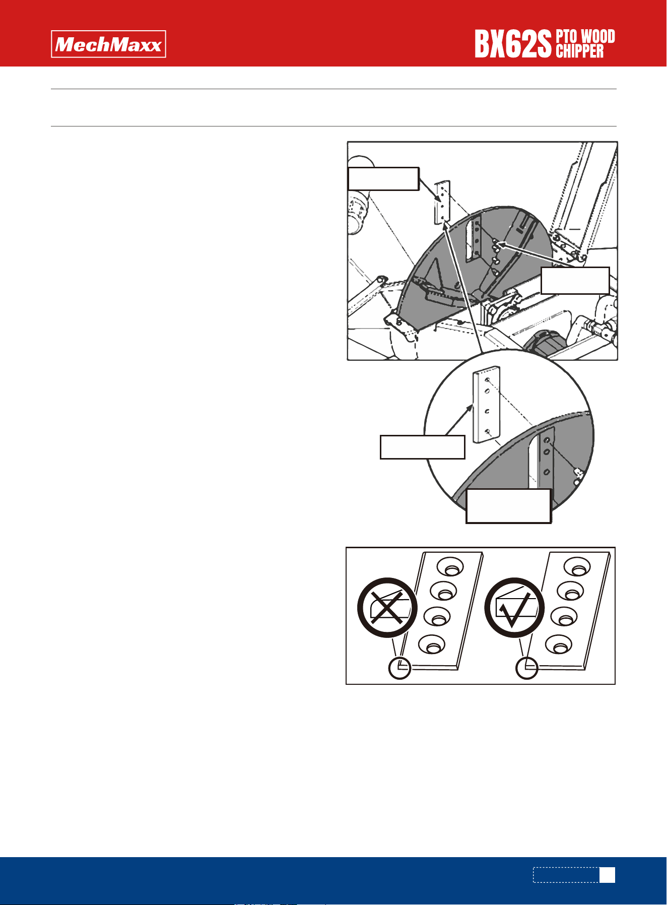
2. Lower the feed hopper down into its working configura-
tion:
a. remove the nuts on the hopper anchor bolts,
b. unpin and the feeder hopper latch
c. carefully lower the hopper and secure it with the with
the nuts on the anchor bolts. d. Secure the feed hopper
latch to the discharge chute with the latch pin
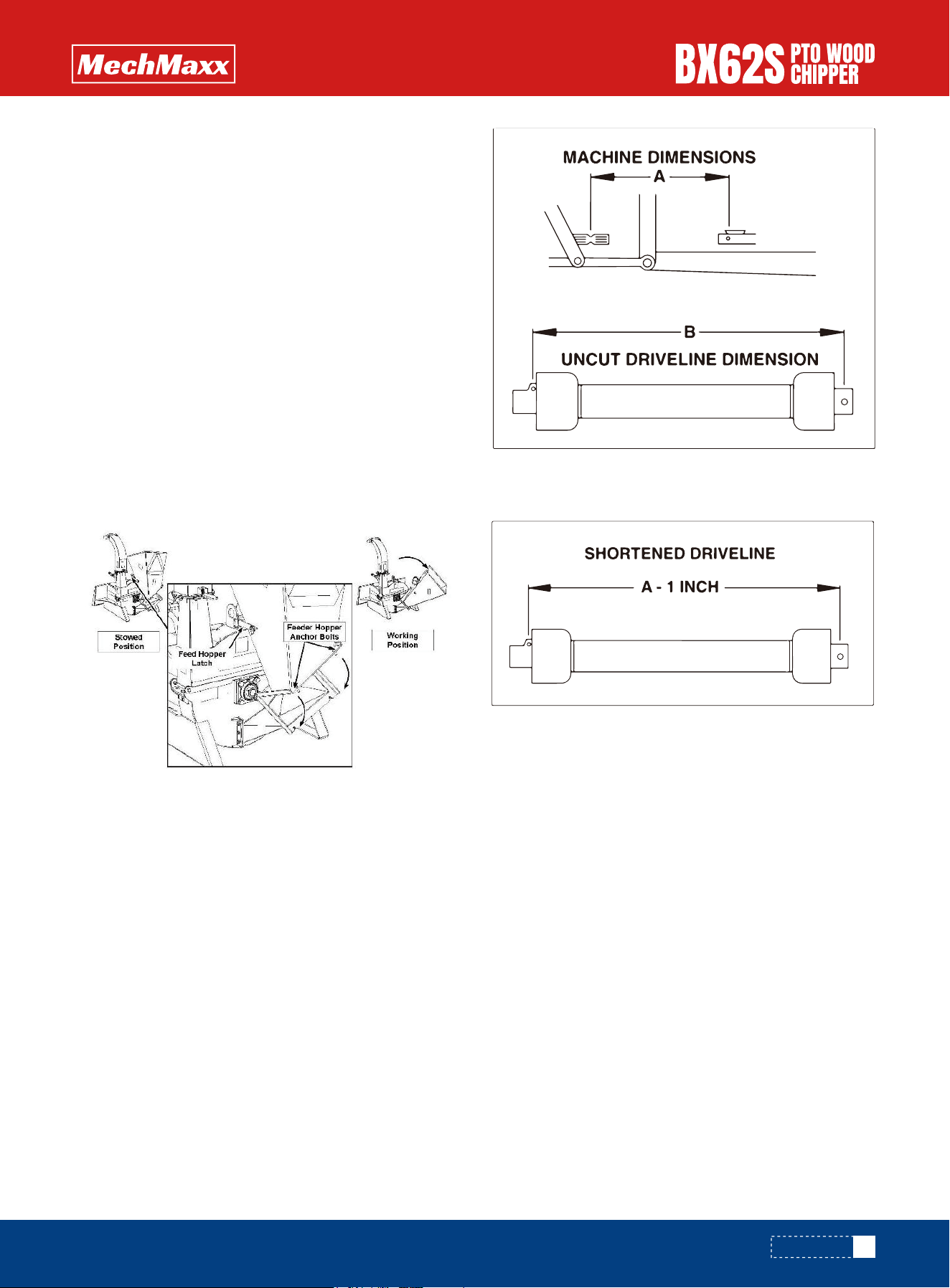
A PTO drive line is supplied with the machine. To accom-
pany the variety of 3 point hitch geometry available
today, the drive line can be too long for most machines or
too short for others. It is very important that the drive
line be free to telescope but not to bottom out when
going through its working range. If the drive line bottoms
out, the bearings on both the machine and tractor PTO
shaft will be overloaded and fail in a short time.
1. To determine the proper length of the drive line, follow
this procedure:
a. Clear the area of bystanders, especially small children.
b. Attach the chipper to the tractor but do not attach the
drive line.
c. Raise the machine until the input shaft is level with
the tractor PTO shaft.
d. Measure the dimension between the locking grooves
on the tractor PTO shaft and the machine input shaft.
e. Measure the same dimensions on the compressed
drive line.
f. If the compressed drive line dimension exceeds the
machine dimension, the drive line will have to be cut.
MACHINE SET-UP
DRIVELINE DIMENSION
OPERATION
10
www. mechmaxx.com
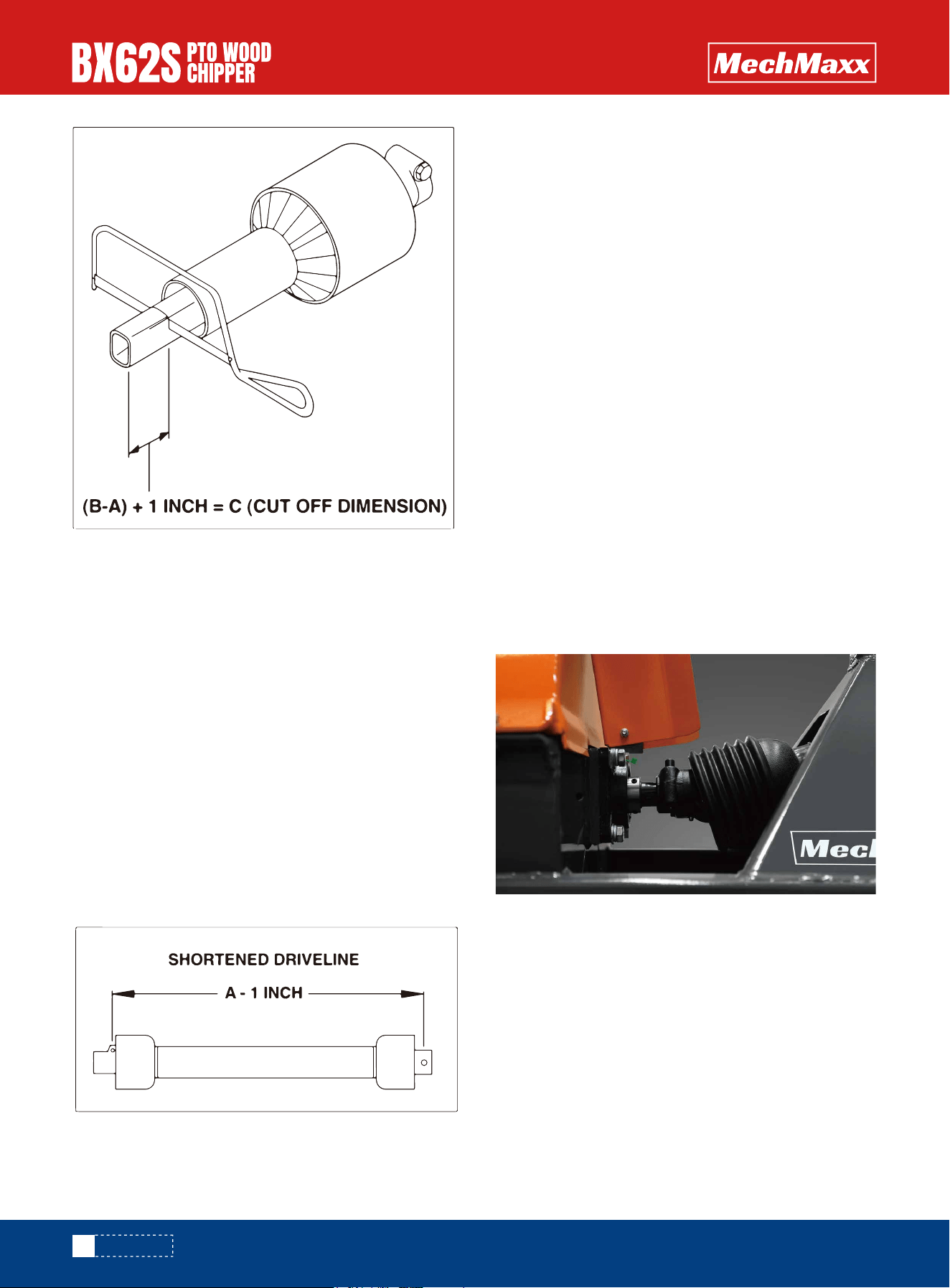
2. When cutting the drive line, follow this procedure:
a. Subtract the machine dimension (A) from the uncut
drive line dimension (B) or (B-A). This dimension deter-
mines how much too long the drive line is.
b. Add another inch (25 mm) to the dimension to be sure
it doesn't bottom out, to determine (C) the cut off dimen-
sion.
c. Use a hacksaw to cut dimension (C) from both ends.
Cut both the plastic tubes and the metal cores.
d. Use a file to remove the burrs from the edges that
were cut.
e. Assemble the 2 ends of the shaft.
f. Make sure the shaft can telescope freely. If it does
not, separate the 2 parts and inspect for burrs or
cuttings on the shaft ends. Be sure it telescopes freely
before installing.
IMPORTANT It may be necessary to add weight to the
lower lift arms to bring them to the required height.
When attaching chipper to a tractor, follow this proce-
dure.
1. Clear the area of bystanders, especially small children.
2. Make sure there is enough room and clearance to
safely back up to the chipper.
3. Place the tractor arms in their full sway position.
4. Back up slowly and align the lower link arms to the
pins on the machine.
5. Mounting without a Quick Hitch
a. Align the left lower link with the left chipper pin.
b. Insert the left pin through the ball and install the
retainer.
c. Align the right arm to the pin by turning the jackscrew
on the arm.
d. Insert the right pin through the ball and install the
retainer. Return the jack- screw to its starting position.
e. Remove the top pin and install the top link. Use the
turnbuckle to align the top link. Insert the pins and install
the retainers. Return the turnbuckle to its original length
and lock.
6. Install the PTO drive line:
NOTE
Be sure the telescoping portion of the shaft is greased
and free of dirt.
a. Slide the collar back on the yoke, align the splines and
slide the yoke on the tractor.
b. Release the collar and make sure the locking pin clicks
into position.
MOUNTING AND UNHOOKING TRACTOR

11
www. mechmaxx.com
OPERATION
7. Slowly raise the machine through its working range to
make sure the telescoping portion of the PTO shaft
doesn't bottom out.
8. Level the machine front and rear, and side to side
using the jackscrew on the right arm and the turnbuckle-
onthe top link.
9. The chipper should always be level on the ground in its
working position.
10. To unhook from the tractor, reverse the above proce-
dure. Always park the machine in a dry, level area. If
vandalism is a problem, remove the PTO drive line and
store in a secure place.
The Wood Chipper is a strong, rugged machine that is
built to a straightforward design which provides consis-
tent chipping of logs up to 6" (152mm)
Always wear personal protective equipment (PPE) when-
ever operating the machine. This includes but is not
limited to protective shoes with slip resistant soles,
protective goggles or face shield, heavy gloves, hearing
protection and protective clothing.
Do not place metal, bottles, cans, rocks, glass or other
solid material into the wood chipper. If something like
this gets into the machine, stop the machine immediate-
ly for a detailed inspection. Stop engine, remove ignition
key and place in your pocket and wait for all moving parts
to stop before inspecting or unplugging. Inspect machine
for damaged or loosened parts before resuming work.
Caution and care should be exercised when feeding
material into the feeder. Do not reach into the hopper
past the curtain barrier.
a. Before beginning to feed the rotor is up to speed.
b. Slowly slide the wooden material into the feed hopper
and move it into the rotor.
c. Do not force the material into the rotor, as the material
engages the rotor, the rotor will draw the material in. Use
continuous lite pressure to guide in the material.
d. Be aware of how much material you feed in, slow down
or stop if the rotor begins to slow down.
e. Do not reach into the feed hopper further than the
curtain to be sure not to contact the blades on the rotor.
f. Use a stick or branch to push any piece of material into
the rotor that does not move on its own. If the jam
persists then stop the engine and wait for the rotor to
stop and then clear the jam. Do not take a chance with
getting your hand caught in the rotor.
g. Ensure your wood chip pile is contained and doesn't
affect the immediate work area.
Although the machine is designed to handle a wide
variety of material without any problem, occasionally it
plugs. When the machine plugs, follow this procedure to
unplug:
a. Clear the area of bystanders, especially small children.
b. Turn off the hydraulics, stop the engine, remove the
ignition key and place it in your pocket and wait for all
moving parts to stop before unplugging.
c. Pull the material out of the feed hopper. Be sure all the
material is out, and nothing is jammed or wedged
between the input opening and the rotor.
d. Pull the material out of the discharge hood. Use a stick
to poke loose any material jammed into the discharge
hood. Do not allow anything to remain in this area.
e. Check that everyone is clear of machine before
restarting engine.
f. Start the engine turn on the hydraulics, and resume
working.
a. Clear the area of bystanders, especially small children.
b. Turn off the hydraulics, stop the engine, remove the
ignition key and place it in your pocket or remove spark
plug wire, and wait for all moving parts to stop before
unplugging.
c. Loosen the feed hopper anchor nuts and raise the feed
hopper.
d. Remove jammed material from inside the rotor
compartment.
CHIPPING OPERATION
UNPLUGGING
SEVERE PLUG

12
www. mechmaxx.com
OPERATION
e. Clean out the discharge area/rotor.
f. Open the upper rotary housing and clean out the hous-
ing.
g. Be sure to turn the rotor by hand to be sure there is
nothing jammed between the rotor and stationary
blades.
h. Close, install and fold down all components opened to
unplug. Tighten fasteners to their specified torque.
i. Check that everyone is clear of machine before restart-
ing engine.
j. Start the engine turn on the hydraulics and resume
working
13
www. mechmaxx.com
MAINTENANCE
By following a careful service and maintenance program
for your machine, you will enjoy many years of trouble-free
operation.
The rotor and ledger blades need to be sharp for the
Chipper to perform as expected. Periodic inspection is
recommended. Keep the blades sharp to reduce the
amount of power required during operation. Watch the
sharpness of the blades when processing material with a
lot of sand, soil or dirt mixed with it. Reverse or sharpen
the blades if the cutting edge becomes dull. Twig breaker
should be inspected for gouges or bent.
The rotor is equipped with 4 blades spaced evenly to keep
the rotor in balance. If one needs to be changed, the one
opposite should also be changed.
It is recommended that the rotor blades be removed from
the rotor when sharpening. Always sharpen the blades at
a 45° angle to provide the best cutting effect as it meets
the stationary blade. Be sure to tighten the blade mount-
ing bolts to their specified torque when reinstalling the
blades to the rotor.
1. Turn off the hydraulics, stop the engine, remove the
ignition key, and place it in your pocket and wait for all
moving parts to stop.
2. Remove the bolt that secures the upper rotor housing,
and carefully open the rotor housing.
3. Manually rotate chipper rotor plate so that the blade is
fully exposed
4. Remove the bolts that hold the rotor blade to the rotor,
remove the blade.
5. Rotate the blade and reinstall or replace with new or
resharpened blade.
6. Ensure the blade is properly oriented, with the leading
edge out. The blade is designed to fit into the rotor one
way only. See diagram for proper installation.
7. Tighten down bolts as specified in the torque chart.
8. Repeat steps for remaining blades.
BLADE AND BREAKER MAINTENANCE
ROTOR BLADES MAINTENANCE
Rotor Blade
Loading Edge
Proper orientation
of Rotor Blade
Rotor Blade
Bolts
MAINTENANCE
14
www. mechmaxx.com
The bx62S is equipped with a ledger (stationary) blade
that acts as a shear for the moving rotor blades. The
ledger blade is designed with 4 usable corners. When the
corner facing the rotor blade rounds over, remove the
blade and reinstall with a different corner facing the rotor
blade. It is recommended that the clearance between the
rotor and stationary blades be set and maintained at
1/32 to 1/16 " (.76 - 1.52 mm) to obtain the best perfor-
mance.
1. Turn off the hydraulics, stop the engine, remove the
ignition key and place it in your pocket and wait for all
moving parts to stop.
2. Remove the 2 bolts that hold the ledger blade to the
ledger mount, remove the blade.
3. Rotate the blade and replace or replace with new or
re-sharpened blade.
4. Hand tighten the bolts and set the clearance
between the ledger and rotor blades at 1/32 - 1/16" .
5. Tighten down bolts as specified in the torque chart .
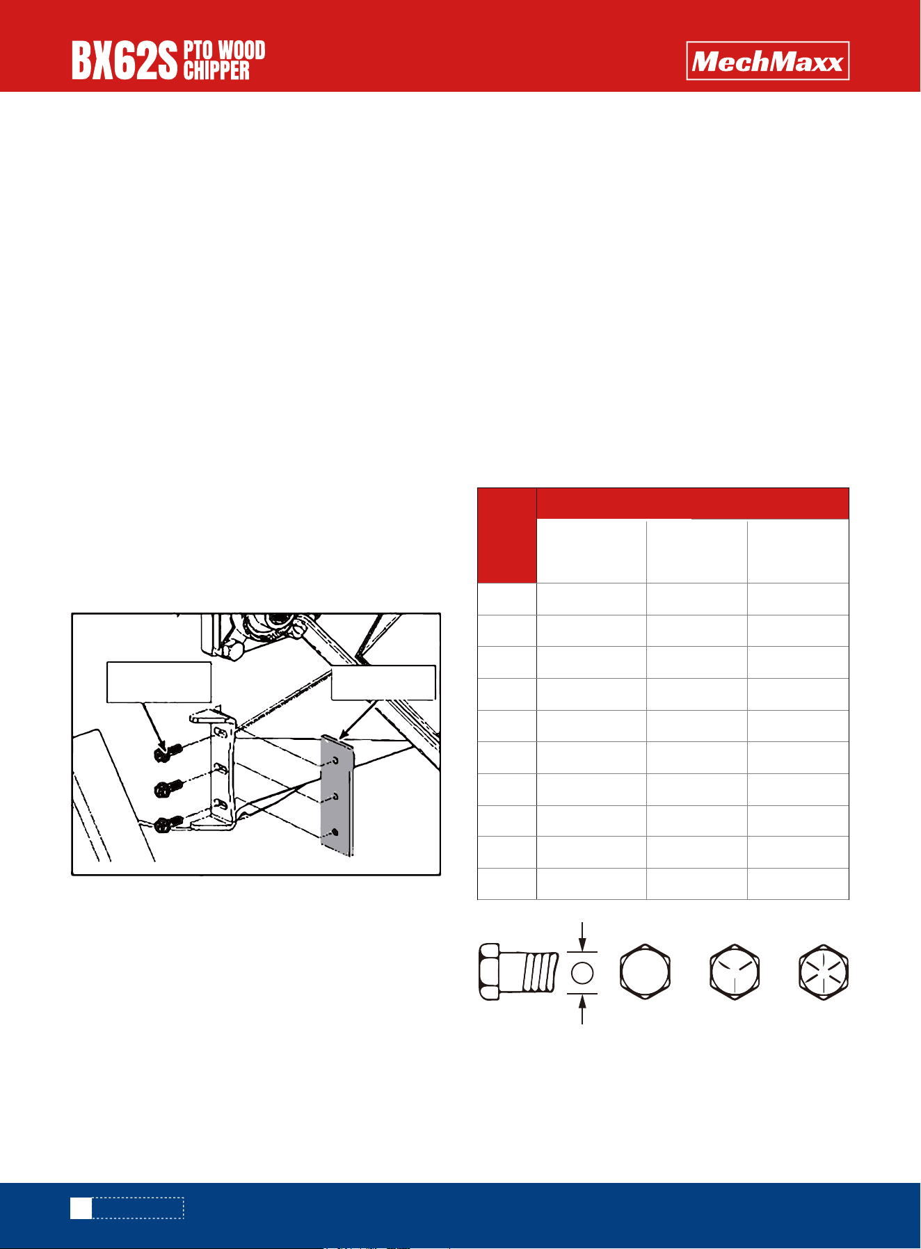
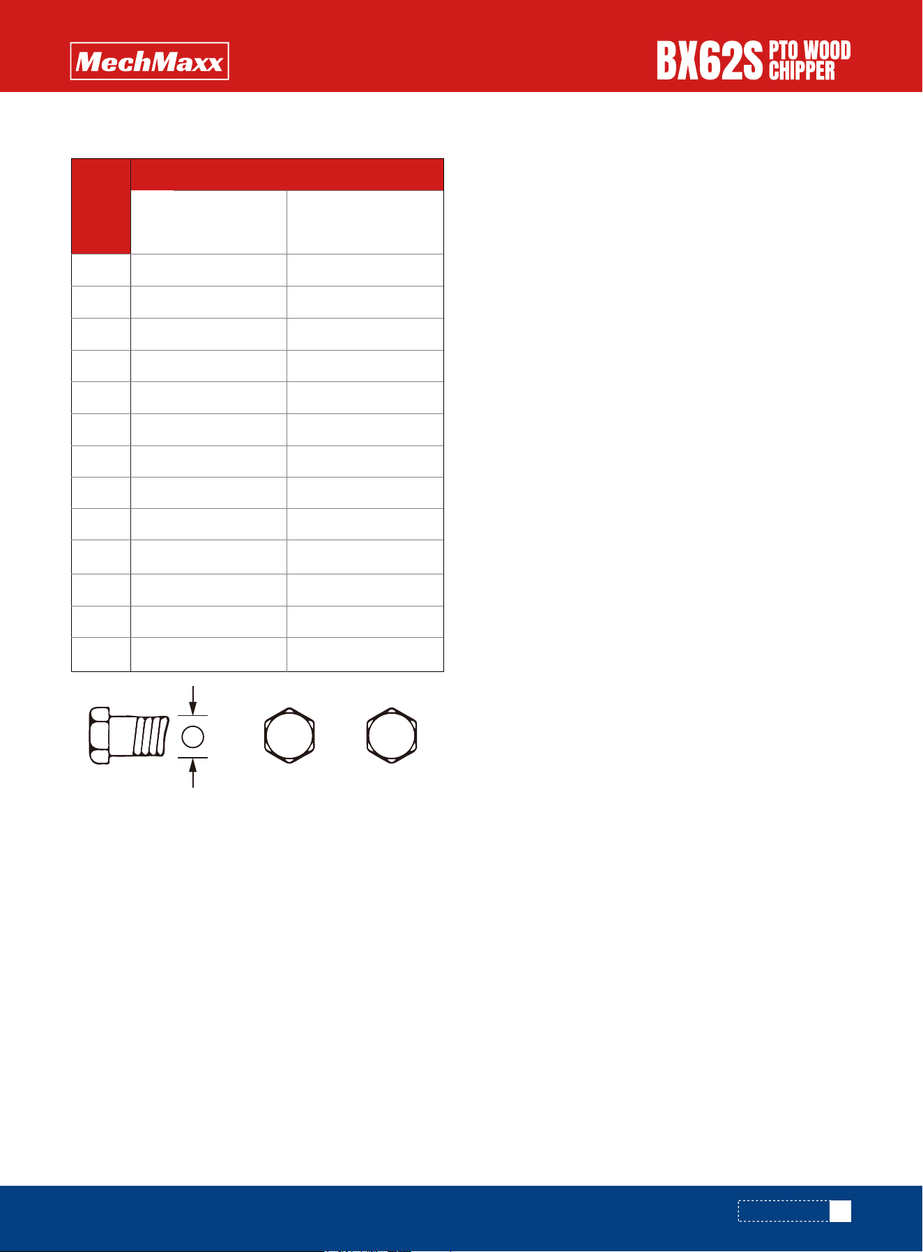
CHECKING BOLT TORQUE
The tables shown below give correct torque values for
various bolts and cap screws. Tighten all bolts to the
torques specified in chart unless otherwise noted. Check
tightness of bolts periodically, using bolt torque chart as
a guide. Replace hardware with the same strength bolt.
Torque figures indicated above are valid for non-greased
or non-oiled threads and heads unless otherwise speci-
fied. Therefore, do not grease or oil bolts or cap screws
unless otherwise specified in this manual. When using
locking elements, increase torque values by 5%.
* Torque value for bolts and cap screws are identified by
their head markings
LEDGER BLADES MAINTENANCE BOLT TORQUE
Ledger Blade
Bolts
Ledger Blade
Bolt
Diameter
SAE 2
SAE-2
A
SAE-5 SAE-8
N.m lb-ft N.m lb-ft N.m lb-ft
SAE 5 SAE 8
Bolt Torque
1/4"
5/16"
3/8"
7/16"
1/2"
9/16"
5/8"
3/4"
7/8"
1"
8
13
27
41
61
95
128
225
230
345
6
10
20
30
45
60
95
165
170
225
12
25
45
72
110
155
215
390
570
850
9
19
33
53
80
115
160
290
420
630
17
36
63
100
155
200
305
540
880
1320
12
27
45
75
115
165
220
400
650
970
ENGLISH TORQUE SPECIFICATIONS
MAINTENANCE
15
www. mechmaxx.com
Bolt
Diameter
8.8
N.m lb-ft N.m lb-ft
10.9
Bolt Torque
M3
M4
M5
M6
M8
M10
M12
M14
M16
M20
M24
M30
M36
0.5
3
6
10
25
50
90
140
225
435
750
1495
2600
0.4
2.2
4
7
18
37
66
103
166
321
553
1103
1917
1.8
4.5
9
15
35
70
125
200
310
610
1050
2100
3675
1.3
3.3
7
11
26
52
92
148
229
450
744
1550
2710
METRIC TORQUE SPECIFICATIONS
MAINTENANCE
A
8.8 10.9
16
www. mechmaxx.com
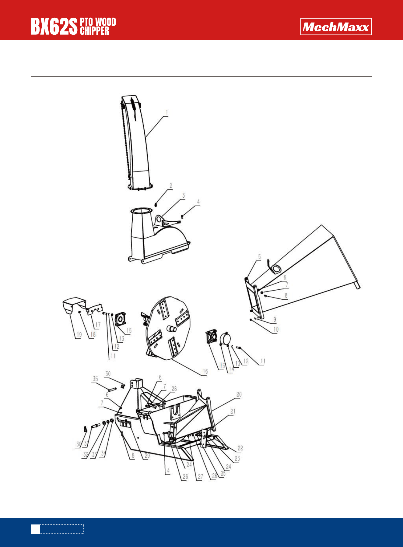
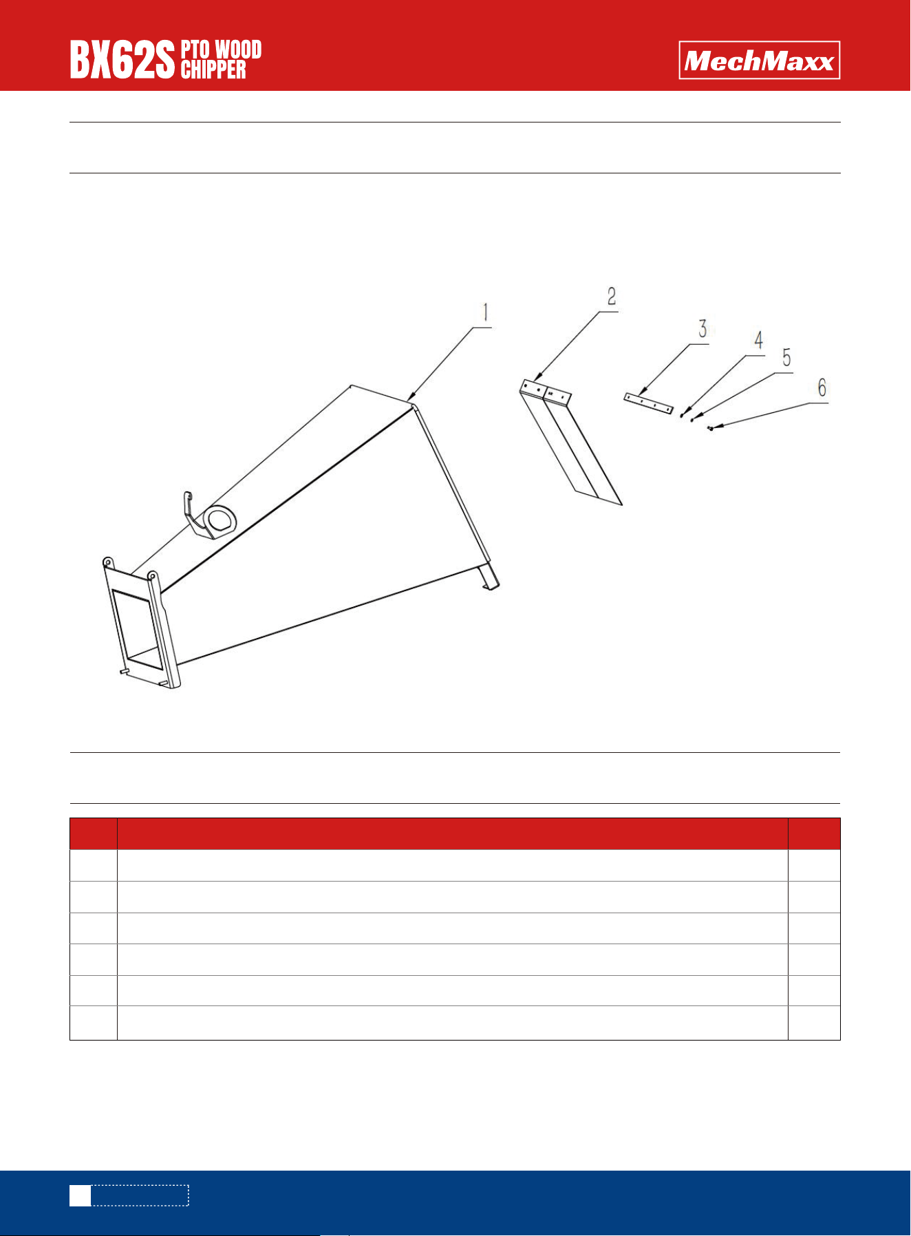
PARTS DIAGRAM
PARTS DIAGRAM

17
www. mechmaxx.com
PARTS LIST
PARTS LIST
REF DESCRIPTION QTY
1
2
3
4
5
6
7
8
9
10
11
12
13
14
15
16
17
18
19
20
21
22
23
24
25
26
27
28
29
Discharge Chute
Lock pin 5
Upper Weldment
Bolt M12*25
Infeed Hopper
Lock nut M12
WASHER 12
Bolt M12*35
WASHER 10
Lock nut M10
Bolt M14*1.5*45
SPRING WASHER 14
WASHER 14
Bearing cover
Bearing UCFU210
Rotor Weldment
Plate
Bolt M10*20
PTO Cover
Housing, Bottom Rotor
Knife, Ledger
Nut M10
SPRING WASHER 10
WASHER 12
Ledger Knife bolt
SPRING WASHER 12
Bolt M12*40
Bolt M12*30
Twig Breaker
1
1
1
2
1
6
6
4
4
4
8
8
8
1
2
1
1
2
1
1
1
2
4
5
2
3
2
2
1
3
2
2
2
2
1
REF DESCRIPTION QTY
30
31
32
33
34
35
Lock pin Φ10
Lower Pin
WASHER 22
SPRING WASHER 22
Fine thread nut M22*1.5
Upper Pin
18
www. mechmaxx.com
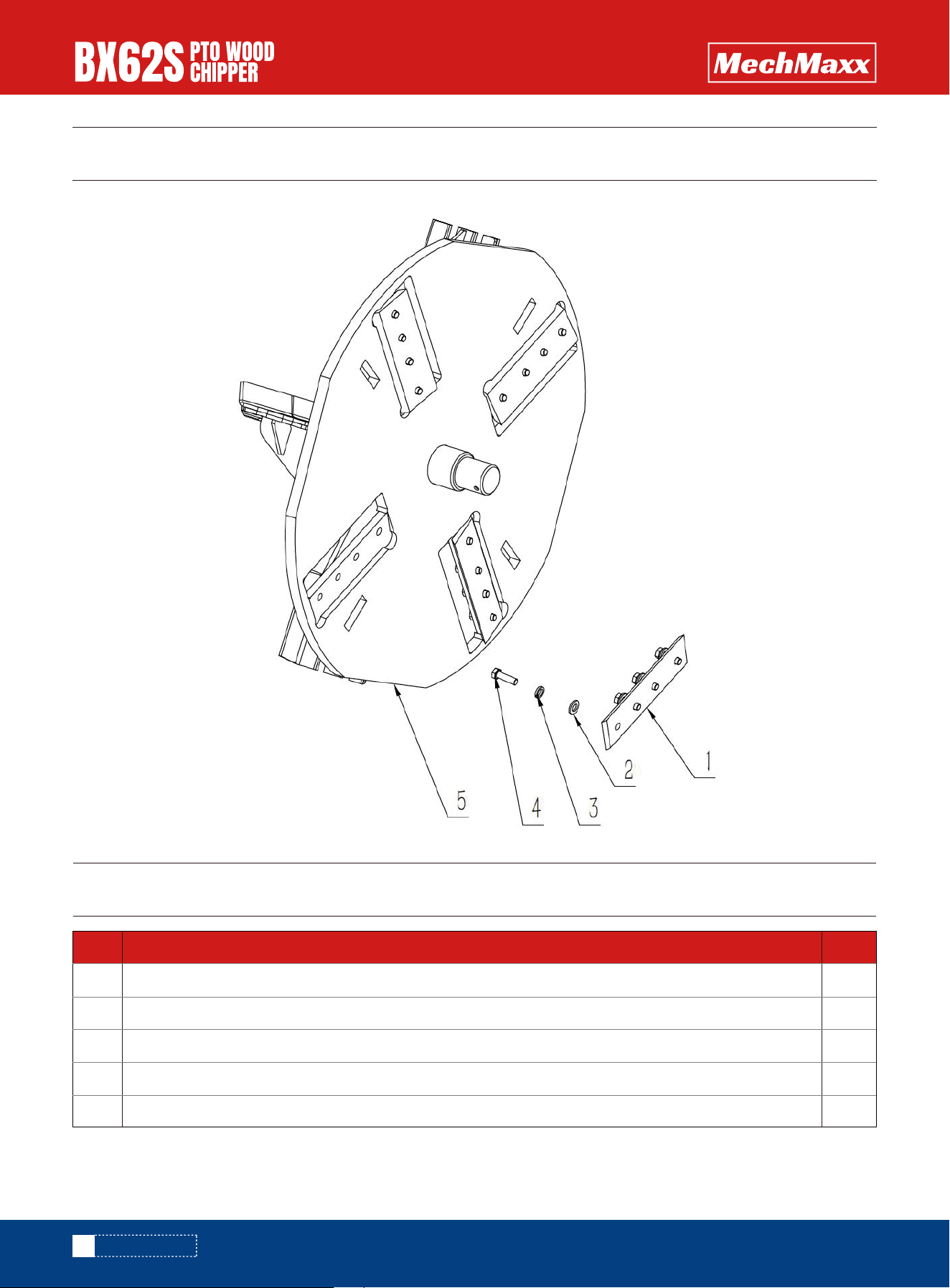
PARTS DIAGRAM
PARTS DIAGRAM
PARTS LIST
4
16
16
16
1
REF DESCRIPTION QTY
B1
B2
B3
B4
B5
Knife, Rotor
WASHER 12
SPRING WASHER 12
Bolt M10*20
Rotor Weldment
19
www. mechmaxx.com
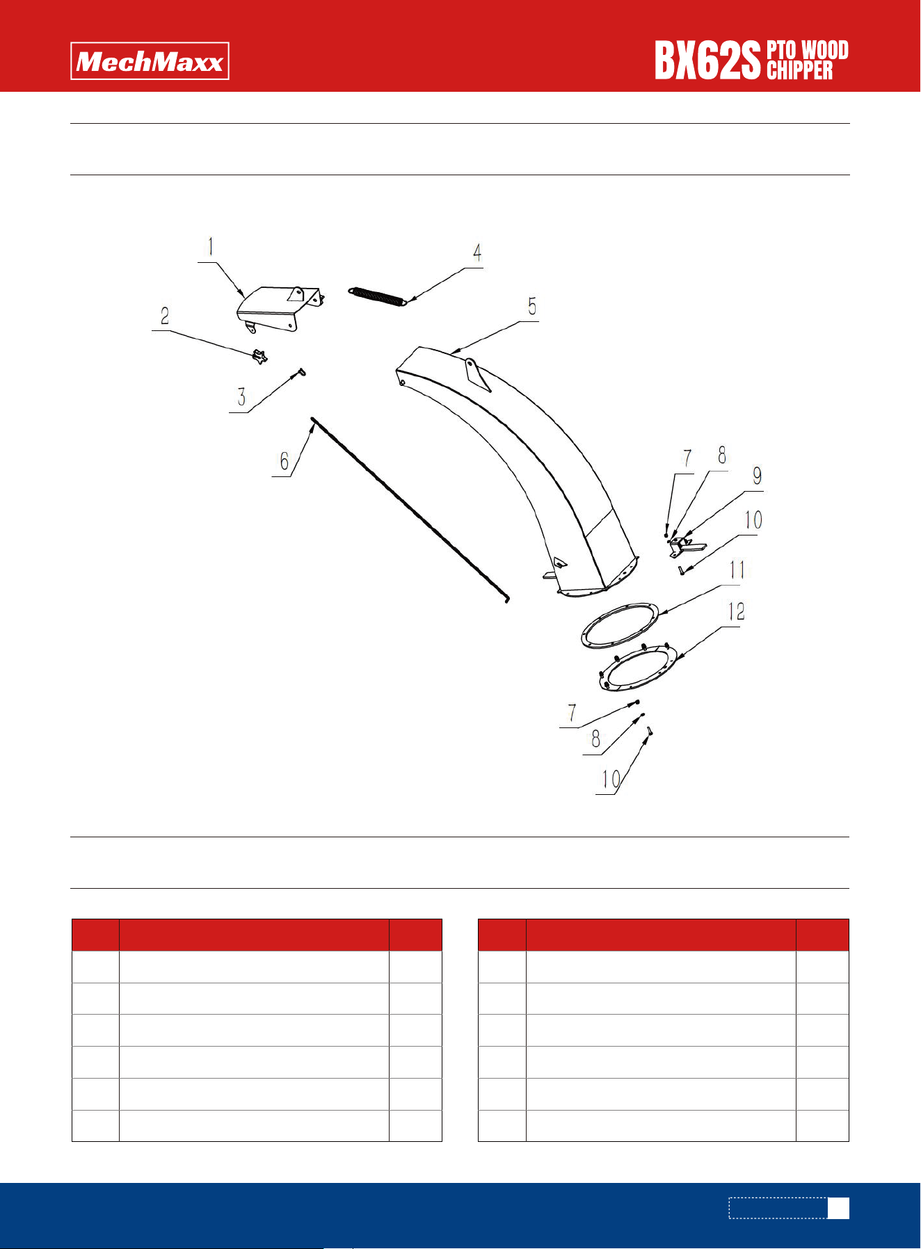
PARTS DIAGRAM
PARTS DIAGRAM
PARTS LIST
1
2
1
1
1
1
REF DESCRIPTION QTY
C1
C2
C3
C4
C5
C6
Deflector, Discharge Chute
Knob 10*40
D shackle
Tension spring 3
Discharge Chute
Short chain
Lock nut M6
Washer 6
Hood Latch
Bolt M6*25
Plate, Spacer Ring
Plate, Hood Capture
8
8
1
8
1
1
REF DESCRIPTION QTY
C7
C8
C9
C10
C11
C12
20
www. mechmaxx.com
PARTS DIAGRAM
PARTS DIAGRAM
PARTS LIST
1
2
1
4
4
4
REF DESCRIPTION QTY
D1
D2
D3
D4
D5
D6
Infeed Hopper
Flap, Hopper
Strap, Hopper Flap
WASHER 6
SPRING WASHER 6
Bolt M6*12