
24 IN. DRUM FAN
SKU: 92024

WARNING
CAUTION
1. Read and save these instructions. Do not operate fan unless you have
read these instructions.
2. Unplug the fan before moving it or performing maintenance. Do not
touch the fan when your hands are wet.
3. Those who are not qualified electricians should not disassemble, repair
or rebuild the fan.
4. Unplug the fan when it is not in use.
5. DO NOT unplug the fan by pulling the cable cord. Unplug by holding
the plug and pulling.
6. DO NOT use the fan when there is damage to the cable cord or plug.
If the supply cord is damaged, it has to be replaced by the manufacturer,
its service agent or similarly qualified persons.
7. DO NOT use the fan with an extension cord.
8. DO NOT use the fan close to fires or flammable material.
9. DO NOT insert your hand or other objects into the grill or the movable
parts.
10. To reduce the risk of fire or electric shock, do not use this fan with
any solid-state speed control device.
11. DO NOT use this fan outdoors, this fan is designed for indoor use only.
1.
Unplug the fan from the socket and clean it with a soft cloth.
2. DO NOT immerse the fan in liquid.
3. Fit the guard onto the fan before starting up the fan.
4. This fan is not intended for use by people (including children) with
reduced physical, sensory or mental capabilities or lack of experience
and knowledge unless they have been given supervision or instruction
concerning use of the fan by a person responsible for their safety.
Supervise children to ensure they do not play with the fan.
SAFETY INFORMATION
1
12. To reduce the risk of fire,electric shock or injury to persons,do not use
replacement parts that have not been recommended by the manufacturer
(e.g. parts made at home using a 3D printer).
2
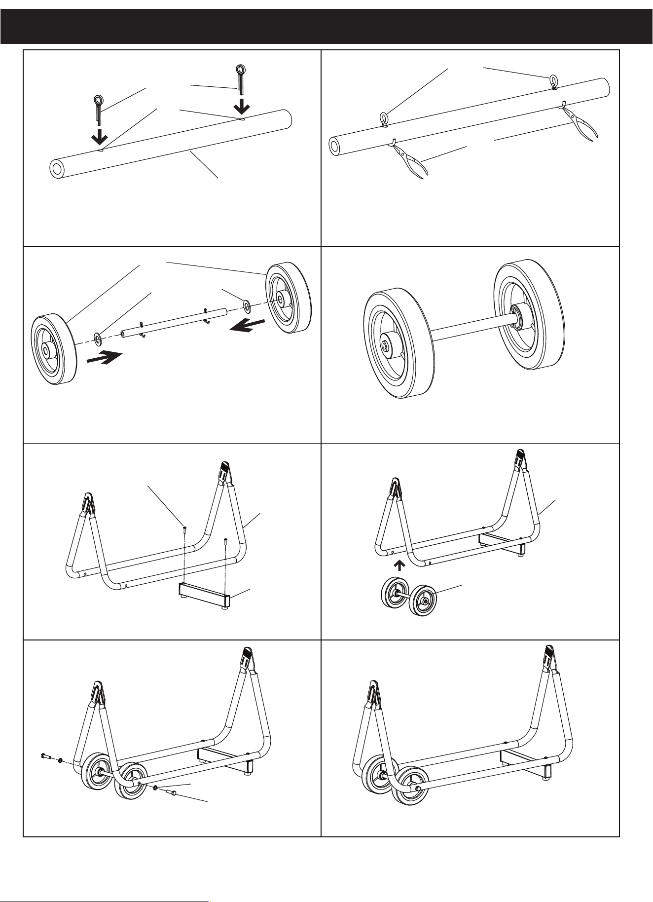
ASSEMBLY INSTRUCTION
1.
3.
5.
7. 8.
6.
4.
2.
spilt pin
spilt pin
plier
hole
wheel shaft
wheel
φ24*φ13*δ1.5 flat washer
Take the spilt pin through the hold of wheel shaft.
Insert the flat washer and wheel to the wheel shaft
Install the wheel assembly into the base bracket
Install the square tube with base bracket by screws ST5*35.
wheel and base bracket assembly
Fastening the wheel assembly into the base bracket by M8*30
screws and
φ8 serrated washers.
Open the spilt pin by plier.
Wheel assembly
wheel assembly
base bracket
base bracket
φ8 serrated washer
M8*30 screw
square tube
ST5*35 screw
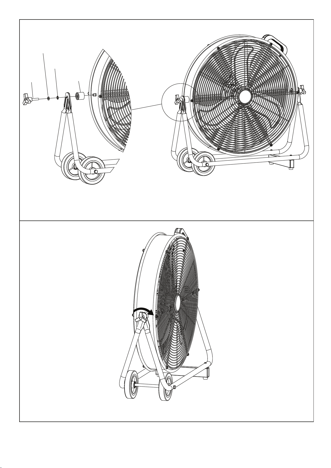
9.
10.
Rubber Pad
φ8 serrated washer
φ16*φ8*δ1.5
flat washer
locking
knob
Assemble the base bracket with two side of drum body by fastening the locking knobs, flat washers, serrated
washers and rubber pads.
Adjust the locking knobs to secure the drum in desired position, and tight it by turning the locking knobs clockwise.
3
4
1. Place the fan on a safe, flat surface where it can not fall or be pulled by
the cord.
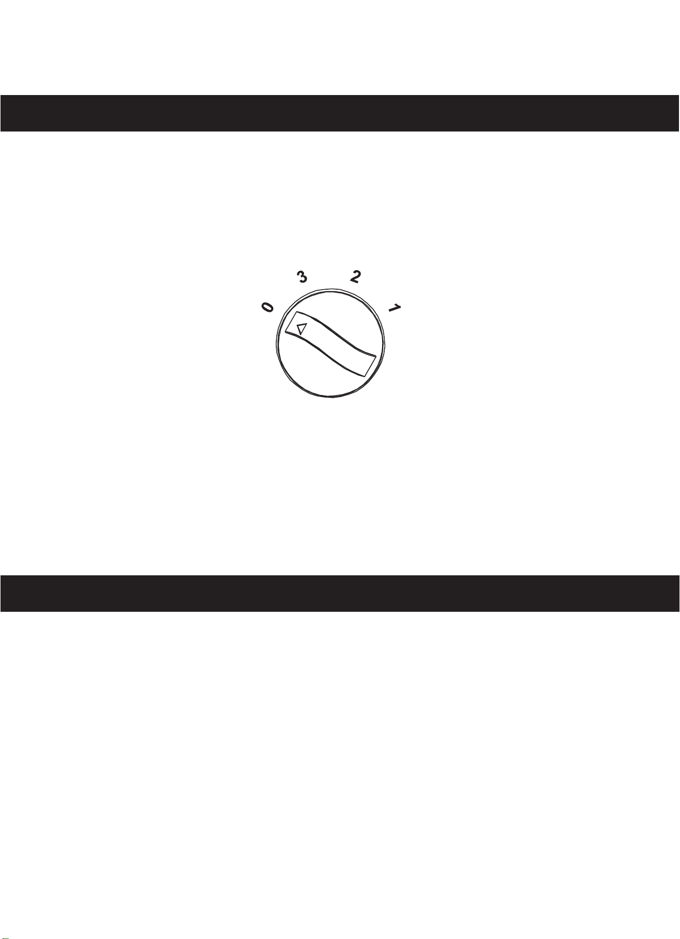
2. Adjust the desired speed by rotating the switch knob at the back of fan.
3.
Tilt the fan head up or down for desired direction of air flow.
OPERATION INSTRUCTION
hgiH3 muideM2
woL1
potS0
Unplug the appliance before cleaning. Don’t use any water for cleaning
metal surfaces. Slightly moisten a cloth and then wipe off the surfaces of
the fan. In order to remove dust from the grill, use a vacuum cleaner or
remove the front grill by removing the securing screws on the edge of the
grill. After cleaning, remount the grill. After doing this, fasten the screws on
the edge of the grill.
CARE AND CLEANING
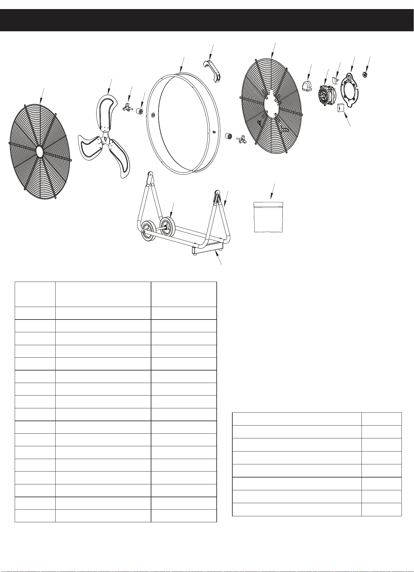
PART LIST
5
1
2
3
4
5
6
14
16
17
7
8
9
10
11
12
13
15
PART DESCRIPTION PART#
1 Front Grill 92024-01
2 Blade 92024-02
3 Locking Knob 92024-03
4 Rubber Pad 92024-04
5 Drum 92024-05
6 Handle 92024-06
7 Rear Grill 92024-07
8 Switch Box 92024-08
9 Motor 92024-09
10 Switch 92024-10
11 Switch Flange 92024-11
12 Switch Knob 92024-12
13 Capacitor 92024-13
14 Base Bracket 92024-14
15 Square Tube 92024-15
16 Wheel Assembly 92024-16
17 Screw Pack 92024-17
Screw Pack List
Description Quantity
Flat washerφ16*φ8*δ1.5 2
Serrated Washerφ8 4
Locking Knob 2
Screw ST5* 35 2
Screw M8* 30 2
Flat Washer φ24*φ13*δ1.5
2
Split Pin 2
PRODUCT MADE IN CHINA
3
IO
6