
Operator’s Manual
www.mechmaxx.com
WARRANTY


OVERALL DIMENSIONS
TABLE OF CONTENTS
TABLE OF CONTENTS
SPECIFICATIONS
SAFETY SIGNS
SAFETY
1
2
2
CONTROL PANEL
PRELIMINARY CHECKS BEFORE DRIVING
13
13
BATTERY CHECK AND RECHARGE
13
STARTING
13
DRIVING
14
LOAD CARRYING
14
LOAD LIMITS
15
UNLOADING
15
NORMAL SWITCH OFF
15
EMERGENCY SWITCH OFF
15
LUBRICATING THE WHEELS
16
TIRES
16
WIRE CONNECTIONS
16
HARDWARE
16
BRAKE SYSTEM
16
CHARGER
16
BATTERY
16
STORAGE
16
GENERAL SAFETY RULES
WORK AREA
PERSONAL SAFETY
4
4
4
POWER TOOL USE AND CARE
4
BATTERY TOOL USE AND CARE
5
SERVICE
5
SPECIFIC SAFETY RULES
5
HANDLE BAR
LIGHTING LAMP
FRONT WHEEL
3
4
7
8
9
10
10
10
10
REAR WHEEL
10
DUMPER BOX
11
UNPACHING THE CONTAINER
CONTENTS SUPPLIED
TO-SCALE HARDWARE
ASSEMBLY
12
KNOW YOUR MACHINE
13
ELECTRICAL WHEELBARROW OPERATION
16
MAINTENANCE
17
19
20
TROUBLESHOOTING
1
www.mechmaxx.com
TABLE OF CONTENTS
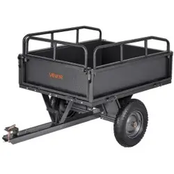
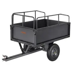
Prepare to experience the durability to take on any job
with the ease, portability, and convenience of your new
electric powered barrow !
Your new Electrical WheelBarrow will more than satisfy
your expectations. It has been manufactured under
stringent quality standards to meed superior perfor-
mance criteria. You will find it easy and safe to operate,
and with proper care, it will give you many years of
dependable service.
MAX performance,MAX Value,MAX Support that’s
Electrical WheelBarrow
Backed by decades of proven manufacturing expertise
Enhanced design features come standard
Engineered for the best user experience
Quality metal parts are used instead of plastic
A robust warranty supports all products
Budget-friendly prices make it practical
PARTS DIAGRAM
PARTS LIST

SPECIFICATIONS
2
www.mechmaxx.com
SPECIFICATIONS
Model EH50
Motor
Battery
Brake System
Monitor
Lighting Lamp
Working Time
Charging Time
Charging Current
Low Speed
Middle Speed
Top Speed
Reverse Speed
Loading Capacity
Tipping Method
Front Wheel
Rear Wheel
Bucket Type
Weight (N.W/G.W.)
Packing Size
1000 W Brushless DC Motor
48 V 32 Ah Lead-Acid Battery
Electromagnetic Brake
Battery Indicator Led Screen
2 (Pcs) 30 W
8-10 Hours
6-7 Hours
4.5 A
0-3.3 km/h
0-4.2 km/h
0-5.0 km/h
0-1.5 km/h
1100 lbs / 7.62 cu.ft.
Hydraulic Tipping
16 x 6.5-8 Tubeless Tyre
13 x 5.00-6 Tubeless Tyre
Welded
450/519 lbs
57 x 31 x 34 in
3
www.mechmaxx.com
SAFETY SIGNS
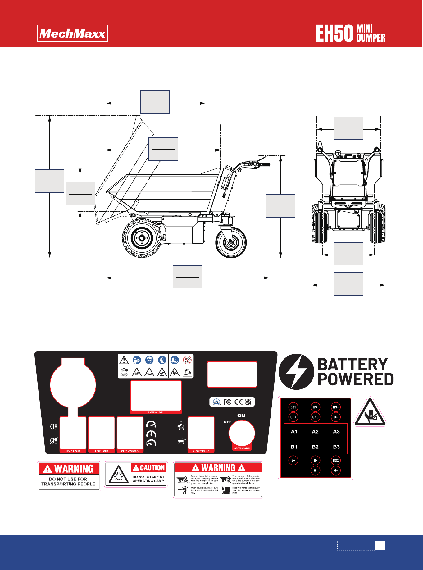
OVERALL DIMENSIONS
The rating plate on your machine may show symbols. These represent important information about the product or instruc-
tions on its use.
SAFETY SIGNS
774mm
30.4”
1668mm
65.6”
1207mm
47.5”
1061mm
41.7”
674mm
26.5”
394mm
15.5”
1067mm
42.0”
1500mm
59.0”
544mm
21.4”

4
www.mechmaxx.com
GENERAL SAFETY RULES
WORK AREA
PERSONAL SAFETY
POWER TOOL USE AND CARE
SAFETY
SAFETY
Read and understand the operator's manual and labels
affixed to the machine. Learn its application and limita-
tions as well as the specific potential hazards peculiar to
it.
Read all safety warnings, instructions,illustrations and
specifications provided with this power tool. Failure to
follow all instructions listed below may result in electric
shock, fire and/or serious injury. Save all warnings and
instructions for future reference. The term "power tool" in
the warnings refers to your mains-operated (corded)
power tool or battery-operated (cordless) power tool.
Keep work area clean and well lit. Cluttered or dark areas
invite accidents.
Do not operate power tools in explosive atmospheres,
such as in the presence of flammable liquids, gases or
dust. Power tools create sparks which may ignite the
dust or fumes.
Keep children and bystanders away while operating a
power tool. Distractions can cause you to lose control.
a) Stay alert, watch what you are doing and use common
sense when operating a power tool. Do not use a power
tool while you are tired or under the influence of drugs,
alcohol or medication. A moment of inattention while
operating power tools may result in serious personal
injury.
b) Use personal protective equipment. Always wear eye
protection. Protective equipment such as a. dust mask,
non-skid safety shoes, hard hat or hearing protection used
for appropriate conditions will reduce personal injuries.
c) Prevent unintentional starting. Ensure the switch is in
the off-position before connecting to power source and/or
battery pack, picking up or carrying the tool.
d) Remove any adjusting key or wrench before turning the
power tool on. A wrench or a key left attached to a rotat-
ing part of the power tool may result in personal injury.
e) Do not overreach. Keep proper footing and balance at all
times. This enables better control of the power tool in
unexpected situations.
f) Dress properly. Do not wear loose clothing or jewellery.
Keep your hair and clothing away from moving parts.
Loose clothes, jewellery or long hair can be caught in
moving parts.
g) If devices are provided for the connection of dust
extraction and collection facilities, ensure these are
connected and properly used. Use of dust collection can
reduce dust-related hazards.
h) Do not let familiarity gained from frequent use of tools
allow you to become complacent and ignore tool safety
principles. A careless action can cause severe injury
within a fraction of a second.
i) Do not operate the utility machine in the rain. This may
result in the of loss of control, slipping and falling which
may increase the risk of personal injury.
a) Do not force the power tool. Use the correct power tool
for your application. The correct power tool will do the job
better and safer at the rate for which it was designed.
b) Do not use the power tool if the switch does not turn it
on and off. Any power tool that cannot be controlled with
the switch is dangerous and must be repaired.
c) Store idle power tools out of the reach of children and
do not allow persons unfamiliar with the power tool or
these instructions to operate the power tool. Power tools
are dangerous in the hands of untrained users.
d) Maintain power tools and accessories. Check for
misalignment or binding of moving parts, breakage of
parts and any other condition that may affect the power
tool' s operation. If damaged, have the power tool repaired
before use. Many accidents are caused by poorly main-
tained power tools.
e) Use the power tool, accessories and tool bits etc. in
accordance with these instructions,taking into account
the working conditions and the work to be performed. Use
of the power tool for operations different from those
intended could result in a hazardous situation.
f) Keep handles and grasping surfaces dry, clean and free
from oil and grease. Slippery handles and grasping surfac-
es do not allow for safe handling and control of the tool in
unexpected situations.

5
www.mechmaxx.com
SAFETY
a) Recharge only with the charger specified by the manu-
facturer. A charger that is suitable for one type of battery
pack may create a risk of fire when used with another
battery pack.
b)Use power tools only with specifically designated
battery packs. Use of any other battery packs may
create a risk of injury and fire.
BATTERY TOOL USE AND CARE
c) When battery pack is not in use, keep it away from
other metal objects, like paper clips, coins, keys, nails,
screws or other small metal objects, that can make a
connection from one terminal to another. Shorting the
battery terminals together may cause burns or a fire.
d) Under abusive conditions, liquid may be ejected from
the battery; avoid contact. If contact accidentally
occurs, flush with water. If liquid contacts eyes,
additionally seek medical help. Liquid ejected from the
battery may cause irritation or burns.
e) Do not use a battery pack or tool that is damaged or
modified. Damaged or modified batteries may exhibit
unpredictable behaviour resulting in fire, explosion or risk
of injury.
f) Do not expose a battery pack or tool to fire or excessive
temperature. Exposure to fire or temperature above 130
°C may cause explosion. NOTE The temperature , 130 °C"
can be replaced by the temperature ,, 265 °F".
g) Follow all charging instructions and do not charge the
battery pack or tool out side the temperature range speci-
fied in the instructions. Charging improperly or at
temperatures outside the specified range may damage
the battery and increase the risk of fire.
a) Have your power tool serviced by a qualified repair
person using only identical replacement parts. This will
ensure that the safety of the power tool is maintained.
b) Never service damaged battery packs. Service of
battery packs should only be performed by the manufac-
turer or authorized service providers.Never stop the
machine on a slop surface.
c) For battery tools:
1) Charge and store the battery pack in an ambient
temperature of 18 - 24°C (65 - 75°F) to ensure the
longest battery life and best performance. Do not charge
or store the battery pack in temperatures below O°C (32
°F) and above 45°C (113°F).
2)Recharge only with the charger specified by the manu-
facturer. A charger that is suitable for one type of battery
pack may create a risk of fire when used with another
battery pack.
3)Use power tools only with specifically designated
battery packs. Use of any other battery packs may create
a risk of injury and fire.
4)When battery pack is not in use, keep it away from
other metal objects, like paper clips, coins, keys, nails,
screws or other small metal objects that can make a
connection from one terminal to another. Shorting the
battery terminals together may cause burns or a fire.
5)Under abusive conditions, liquid may be ejected from
the battery; avoid contact. If contact accidentally occurs,
flush with water. If liquid contacts eyes, additionally seek
medical help. Liquid ejected from the battery may cause
irritation or burns.
SERVICE
SPECIFIC SAFETY RULES
Thoroughly inspect the area to be worked, keep the work-
ing area clean and free of debris to prevent tripping.
Operate on a flat level ground.
Never place any part of your body where it would be in
danger if movement should occur during assemble ,instal-
lation ,and operation ,maintenance, repairing or moving.
Keep all bystanders,children ,and pets at least 23m(75-
feet) away .If you are approached, stop the unit immedi-
ately.
Do not mount on dump box and never carry passengers.
Never park the machine in a place with unstable ground
which could give way .particularly when it is full.
Disengage clutch lever before starting the engine.
Start the engine carefully according to instructions and
with feet well away from the moving parts.
Never leave the operating position when the engine is
running.
Always hold the unit with both hands when operating
.Keep a firm grip on the handlebars.Be aware that the
machine may unexpectedly bounce upward or jump
forward if the machine should strike buried obstacles
such as large stones.
Walk, never run with the machine.

6
www.mechmaxx.com
SAFETY
Do not overload the machine capacity .Drive at a safe
speed ,adjusting the speed to the slope of the land .the
surface conditions of the road ,and the weight of the load.
Use extreme caution when in reverse or pulling the
machine towards you.
Exercise extreme caution when operating on or crossing
gravel drives ,walks,or roads.Stay alert for hidden hazards
or traffic.
On soft ground ,drive at the first forward /reverse gear. Do
not rapidly accelerate ,turn sharply or stop.
Pay the utmost attention when working on frozen ground
as the machine may tend to skid.
If possible ,avoid driving on pebble river bed, crushed
stone terrains, steel concrete ,stumpy field, logs etc.,
since such operation causes fatal damage or shortens life
span of tracks.
Do not operate the machine in confined areas where there
may be a risk of crushing the operator between the
machine and another object.
Never operate the machine on slopes where angle is over
20°.
When moving over a slope, whether moving forward or in
reverse ,always make certain that the weight is evenly
balanced .Always move in directions parallel with the
slope (up or down),To avoid danger ,do not shift gears on
slopes.
When tipping the load from a dumper ,the center of gravity
will change continuously and the ground conditions will be
essential for the stability of the machine .There are
special hazards for dumpers working on soft ground and
when the load is sticking to body e.g. wet clay.
7
www.mechmaxx.com
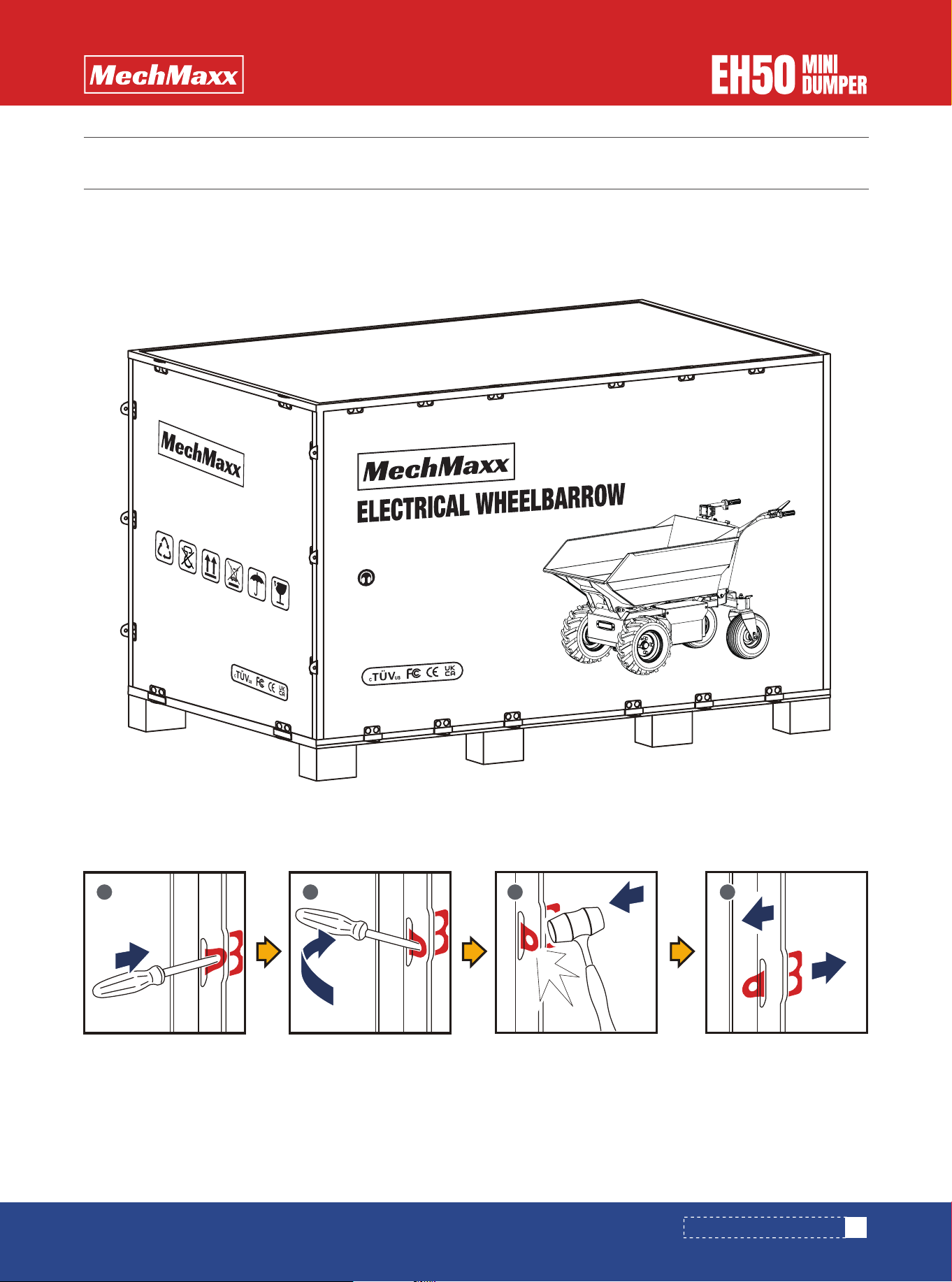
UNPACHING THE CONTAINER
Use the screwdriver and hammer to open all the side locks.
UNPACHING THE CONTAINER
1 2 3 4
No noise
www.mechmaxx.com
N.
MODEL:
DIMENSION:
W./G.W.:
ELECTRICAL
WHEELBARROW
8
www.mechmaxx.com
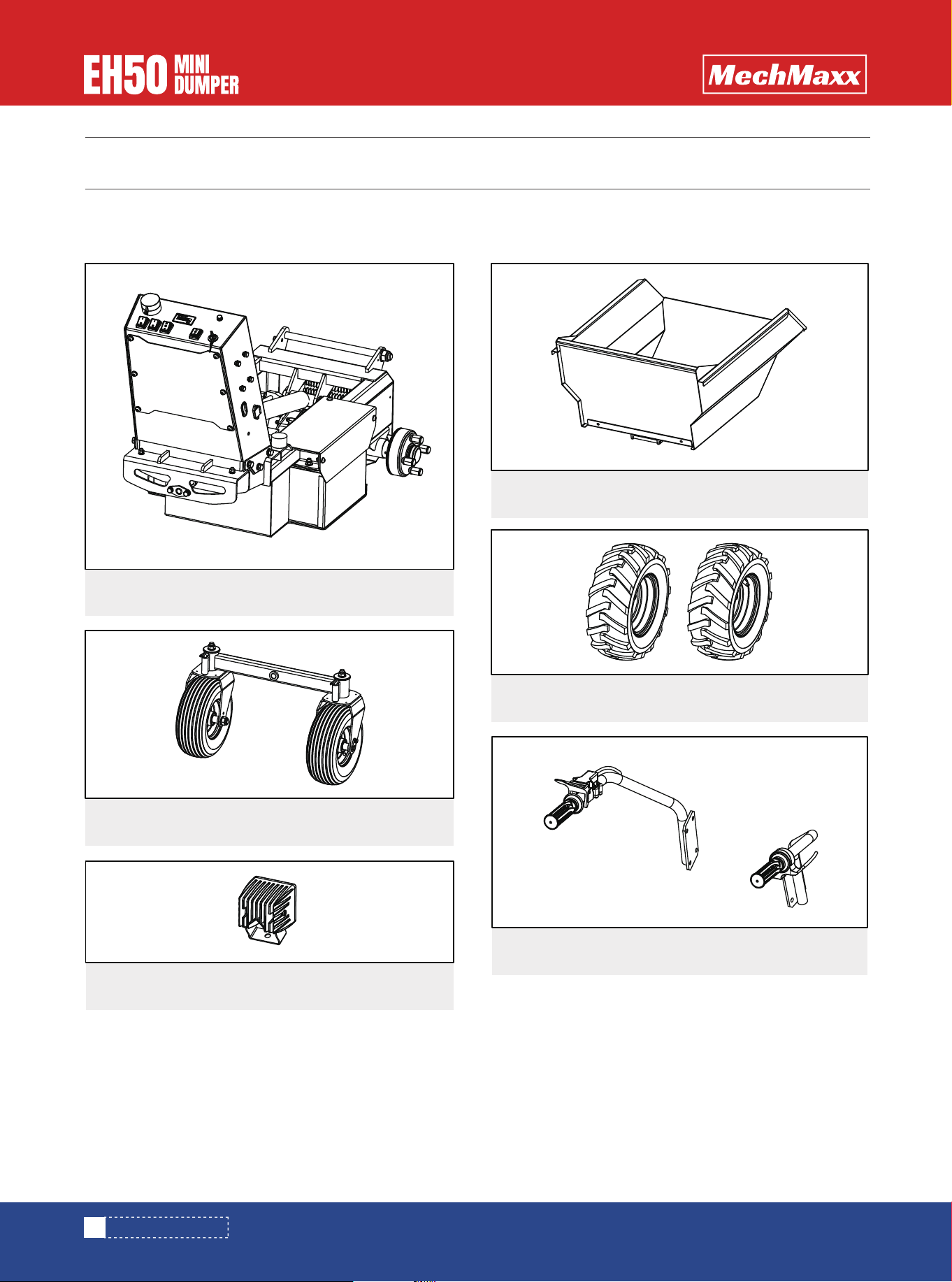
CONTENTS SUPPLIED
The Electrical wheelbarrow comes partially assembled and is shipped in carefully packed package. After all the parts
have been removed from the package, you should have:
Verify all component and hardware quantities are correct prior to assembling the Wood chipper.
Main Frame1x
1x
1x
Wheels
1x
Dumper Box
Rear Wheel
1x Handle Bar
CONTENTS SUPPLIED
1x Lighting Lamp
9
www.mechmaxx.com
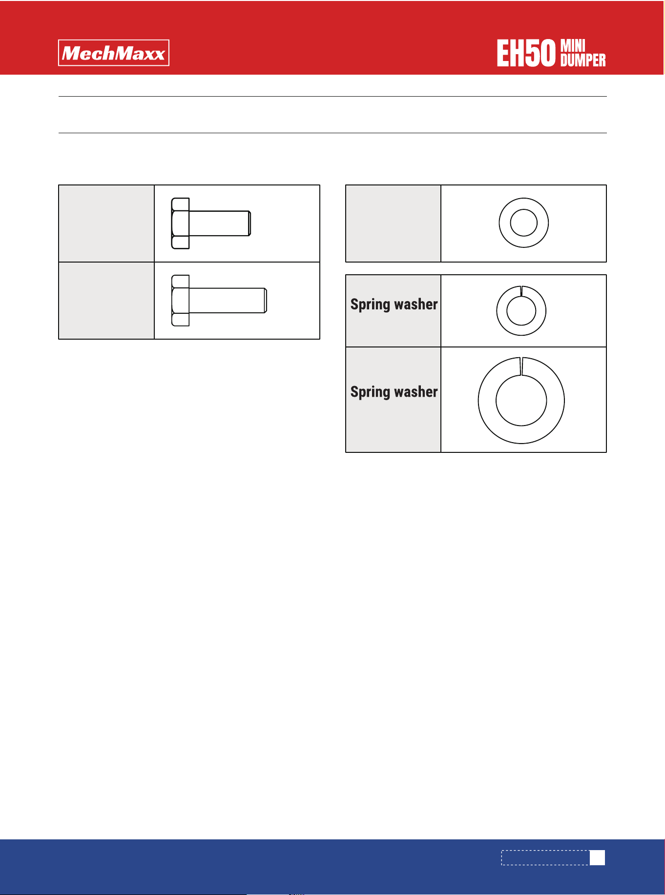
TO-SCALE HARDWARE
TO-SCALE HARDWARE
Hardware graphics are printed at 1:1 scale for ease of identification. Simply place the hardware over the image in the
tables to verify it is the correct size.
M8 X 25mm
Hex bolt
8X
M8 X 20mm
Hex bolt
3X
8
Flat washer
11X
11 X
8
8X
14
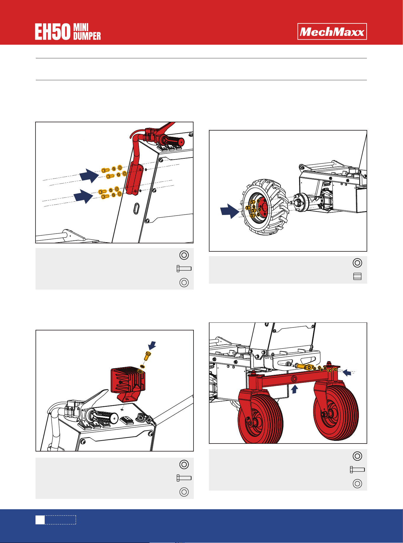
ASSEMBLY
Mount the right and left handle with M8×25 bolts,(See
Figure 1)
Mount the light and fasten it with M8x20 nuts.(See
Figure 2)
Mount the front wheels and fasten them with M14 hub
nut and Spring washer 14 Mount the rear wheels and
fasten them with Axle sleeve.( See Figure 3)
ASSEMBLY
10
www.mechmaxx.com
Hex bolt M8 X 25mm
Flat washer 8
8X
8X
M14 hub nut8X
Hex bolt M8X 20mm
Flat washer 8
2X
2X
Hex bolt M8 X 20mm
Flat washer 8
1X
1X
Figure 2
Figure 3
Figure 4
Spring washer 148X
Spring washer 88X
Spring washer 81X
Spring washer 82X
HANDLE BAR
LIGHTING LAMP
FRONT WHEEL
REAR WHEEL
Mount the Rear Axle and fasten it with M8x20 nuts.(See
Figure 4)
Figure 1
ASSEMBLY
11
www.mechmaxx.com
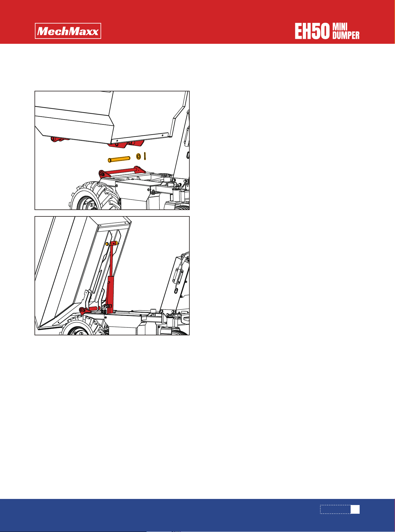
Figure 5
Figure 5
Mount the dumper box and fasten it with M8 nuts.( See
Figure 5)
DUMPER BOX
12
www.mechmaxx.com
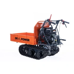
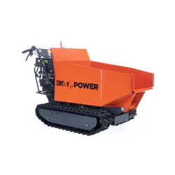
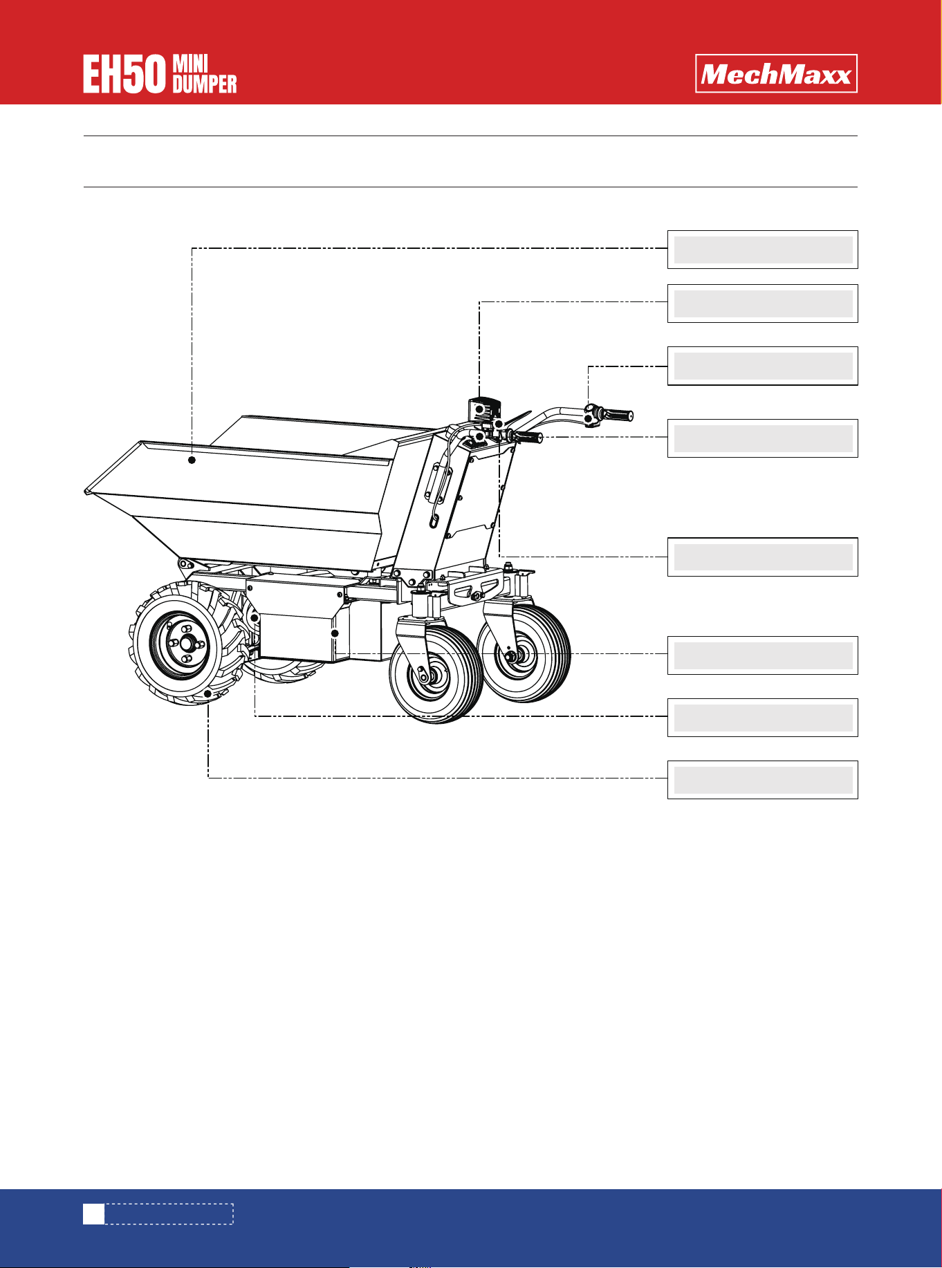
KNOW YOUR MACHINE
Dumper Box
Lighting Lamp
Control Panel
Battery
1000W DC motor
16x6.5-8 wheel
KNOW YOUR MACHINE
Safety control Lever
Thumb throttle lever
The red button on the handle controls forward and
reverse direction,when at "F" position,machine will run
forward,and when pressing it to "R" ,machine will run
backward.
THUMB THROTTLE LEVER
When you want to turn right or left,firmly hold the handle
bar to control the Universal Wheels to turn right or left.
the machine will run forward and backward directly.
UNIVERSAL WHEEL
Squeeze the control lever, clutch engaged. Release the
lever, clutch disengaged.
It controls tipping of the dump box.Detailed operations
please refer to following instructions.
SAFETY CONTROL LEVER
TIPPING BUTTON
You can turn on the light when the light is not good.
LIGHT
13
www.mechmaxx.com
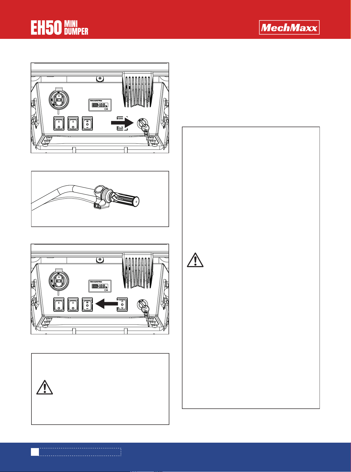
ELECTRICAL WHEELBARROW OPERATION
ELECTRICAL WHEELBARROW OPERATION
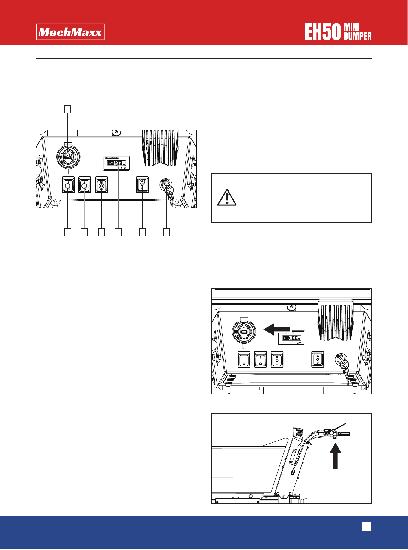
1. Battery Switch: Turn the Button to "ON" /"OFF"
position,machine power will be on/off. And 5 electricity
indicator will be on, when the button to "ON" position.
2. Front Light Button
3. Light (on the control Panel )Button
4.Speed Button: choose speed 1.2.3
5.Voltmeter
6.Tipping Button
7.Switch Lock:Turn on/off the dumper by turning the keys
to on/off position.
Push the tipping handle, and hold in position.
To raise the hopper, push the tipping handle forward until
the hopper has reached the desired position. To stop
raising the hopper, simply release the tipping handle.
To lower the hopper, first pull the tipping handle back with
hand. When the hopper is lowered to the original position,
release the tipping handle back to its original position.
1.Turn on the battery
2.Turn on the dumper with keys
3.Check the battery percentage with the display
1. Turn on the battery(ON position).
2.Make sure the transmission clutch is at STOP position.
To ensure proper operation and maximum service life, it
is necessary to carry out some preliminary checks before
working session:
-Battery: check battery status with display.
-Tracks: check for tension, looseness or damage.
-Cleaning: check for any dirt or debris.
-Tightening of parts: check for any loosening and solve it.
-Transmission clutch lever: check operation.
-Steering clutch levers: check operation.
-Container box: check that it is locked in the lowered
position
For all detailed maintenance activities, refer to Mainte-
nance'chapter.
Battery:Recharge the battery with appro-
priate charger
Avoid that dust or water gets into the
charging port
CONTROL PANEL BATTERY CHECK AND RECHARGE
STARTING
PRELIMINARY CHECKS BEFORE DRIVING
1
2 3 4 5 6 7
ELECTRICAL WHEELBARROW OPERATION
14
www.mechmaxx.com
1.Follow the procedure for starting the engine.
2.Push the speed button to the 1,2 or 3 position.
3.Select the desired gear ("F" for normal gear or "R" for
reverse gear).
4.Press the red accelerator lever to operate the dump-
er.The machine will move.
5.Release the red accelerator lever to brake.
3. Turn on the dumper by turning the keys to on.
4. Engage the gear ("F" is gear and "R" is reverse gear)
5. Choose the speed (1. 2. or 3. )
-Before starting work, check the function
of the brakes.
-To avoid loss of control on steep
descents, proceed to LOW SPEED, with the
throttle in the 1 position.
-The turn may be abrupt. Make sure the
load is well secured to the box. Pay partic-
ular attention when steering on slopes.
To avoid accidents or overturning:
-Respect the safety load limits indicated
at 'Safety indication'section, chapter 1
and at'Load limit'section here below.
-Do not position the load in such a way as
to unbalance the center of gravity of the
machine. Pay attention to the height of
the load. Pay attention to the load width.
-Be sure that the load does not protrude
from the box walls.
-Be sure that the load does not reduce
operator'svisibility.
-Secure the load with strong ropes or
straps, by using the fixing hooks Do not
fasten the ropes to other parts of the
machine.
-When carrying a heavy load,pay special
attention to the balance of the machine,
be sure the load is well distributed and not
tilted. If the load is tilted, it may result in
serious injury and damages, because the
machine may tip over during departure,
braking or traveling on bad roads
-Before operating the machine, check that
the box is locked (side walls and front
wall).
-If you use the truck on a soft or uneven
ground, reduce the
-Speed and pay close attention.
-Use the low gear and the throttle in the 1
position on steep descents. Never use
reverse gear down hill.
-Be extremely careful during starting,
stopping or steering the machine, when
working on slopes.
DRIVING
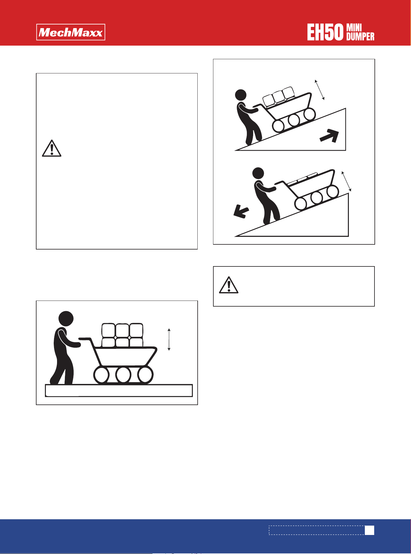
LOAD CARRYING
15
www.mechmaxx.com
ELECTRICAL WHEELBARROW OPERATION
Flat terrain condition
- Max load = 1100 lb
- Max load height *= 32 in*
from bottom surface of the box
1. Take the handle and pull the cable
2. Lift the lever and tilt the box
3. After unloading is complete, return the box to its
original position, push hard on the lever and lock it in
lowered position.
1. Release the red throttle lever to brake and stop the
dumper.
2. Turn the key on the ignition and turn it to OFF
3. Turn the battery switch to OFF position.
1. Release the red throttle lever to brake and stop the
dumper. The machine will stop.
2. Turn the battery switch to OFF position.
Slope condition
-Max admissible slope = 15°
-Max load =
441 lb, for slopes < 10° (17%)
221 lb, for slopes between 10° and 15° (17%÷26%)
-Max load height (from bottom surface of the box) =
12 in for descent
20 in for ascent
*from bottom surface of the box
-Respect the load limits and slope limits
indicated here below
-Under slope condition:
Always drive the machine using first level
gear.
On unstable ground, reduce speed and
proceed with caution
Down hill,reduce engine speed and use
the engine brake.
Be especially careful when moving or
stopping the carriage in slope.
On steep slopes avoid gear changes and
"U"turns.
Secure the load with ropes.
If stability is not achieved, consider
reducing the load
As visibility decreases on slopes, consid-
er reducing the height of the load.
- Before unloading, stop the machine
- Make sure the unloading area is clear of
people and other objects
LOAD LIMITS
UNLOADING
NORMAL SWITCH OFF
EMERGENCY SWITCH OFF
max 1100 lb
max 32 in
max 441 lb
max 441 lb
max 12 in
max 20 in
16
www.mechmaxx.com
Periodic maintenance and adjustments are required to
maintain the machine in good condition. Carry out inspec-
tion and maintenance according to the maintenance
schedule here below.
Do not start maintenance operations in case of poor
visibility
We recommend you to lubricate the wheels every 100
hours of use.This is to ensure smooth operation
- Stop the machine before proceeding
with any operation of maintenance.
- Before maintenance, wait for the hot
parts to cool down.
- Maintenance operator must use person-
al protective equipment,such as gloves,
shoes, glasses.
- Use recommended products.
- Use original spare parts or their equiva-
lent. The use of non equivalent quality
parts could damage the machine.
LUBRICATING THE WHEELS
Check to make sure the lug nuts on the tires are secure
.Loose lugs nuts may cause the tire to come loose and
result in the loss of control.
TIRES
Periodically check all fasteners/hard wares for proper
tightness. Retighten any loose hard wares.
Regularly examine the charger for damage to the
cord,plug,housing or other parts that may result in the
risk of fire,electric shock or injury.In the event of any
damage,do not use the charger until the damage has been
properly repaired.
Regularly examine the batteries.,always keep them clean
and dry. It is recommended to fully charge your batteries
installed in your machine before each use.Always charge
the batteries in the upright position.For best
results,charge the batteries while installed in your
machine.When in storage keep the battery box and/or
machine in an upright position with the machine drive
wheels and both support legs flat on level ground.
HARDWARE
Periodically check all wire connections.
WIRE CONNECTIONS
Usually check the carbon brush of the motor,need to
change new one if severe wear.
BRAKE SYSTEM
CHARGER
BATTERY
If the machine will not be used for a period longer than 30
days, pay attention to bellow aspects to for proper
storage.
1.The batteries should be fully charged before storage
,and regularly charge them.
2.Keep the batteries clean and dry,do not store the whole
machine in wet environment.Batteries also age during
storage.
3. Protect the batteries from overheating and flames:
danger of explosion.
4.Use clean cloths to clean off the outside of the machine
and to keep the air vents free of obstructions.
5.Store your unit on flat ground in a clean, dry building that
has good ventilation.
6. During storage, do not leave the wheelbarrow exposed
to direct sunlight.
7. Before storing the batteries, separate them from any
electrical circuit and place them preferably in a cool and
dry place.
8. During storage, disconnect the batteries from the
motor unit by separating the connectors and eventually
the cables from the terminals.
STORAGE
MAINTENANCE
MAINTENANCE

17
www.mechmaxx.com
Machine does not run.Machine
was running but suddenly
stopped.Short run time(less
than 1-3 hours per charge.)Ma-
chine runs sluggishly.Battery
lights do no illuminate.
Sometimes the machine done't
run but other times it does.
Battery makes a sizzling or
gurgling noise when charging.
It is normal for the batter-
ies to make noise or swell
slightly while charging.and
is not reason for concern.
Machine is overloaded
and/or running conditions
are too stressful.
Charge the battery.A new battery should have been
charged for at least 12 hours before using the
machine for the first time.After first time use,re-
charge the battery until the green charge light
illuminates.
There is no sure way to tell if your charger is work-
ing unless you have a volt meter.If you suspect
there is a problem with your charger,contact the
customer service.
Check all wires and connectors.Make sure the
motor harness connector is plugged into the
battery,and that there are no loose wires.
Do not charge the battery longer than 30 hours.If
you suspect damage due to overcharging,contact
customer service.
Make sure not to overload the machine,maximum
capacity is 1100 lb or run in a less stressful
environment.
If your battery does not make noise or swell slightly
during charging,it does not mean that it is not
accepting the charge
Check all wire connections to make sure they are
tight.
Contact customer service for diagnosis and/or
repair.
No Action required.
Charge the battery as showed in the Owner's
manual.
Check all connectors.Make sure the charger
connector is plugged into the battery box,and that
the charger is plugged into to outlet.
Make sure power flow to the wall outlet is "ON".
TROUBLESHOOTING
TROUBLESHOOTING
Remedy
Problem
Cause
Undercharged battery.
Charger is not working.
Loose wire or loose
connectors.
Dead battery
Overcharged battery
Loose wire or connector.
Motor or electrical damage.

18
www.mechmaxx.com
TROUBLESHOOTING
One or more tires are flat.
Machine feels loose or less
solid then initial assembly
Inflate the tire with proper quantity air.
Patch or replace damaged inner Tube.
Replace or tighten tire air valve.
Remedy
Problem
Cause
Tire has lost air.
Tire puncture.
Leaky tire air valve.
Retighten all hardware using tools
Hardware has become loose.
19
www.mechmaxx.com
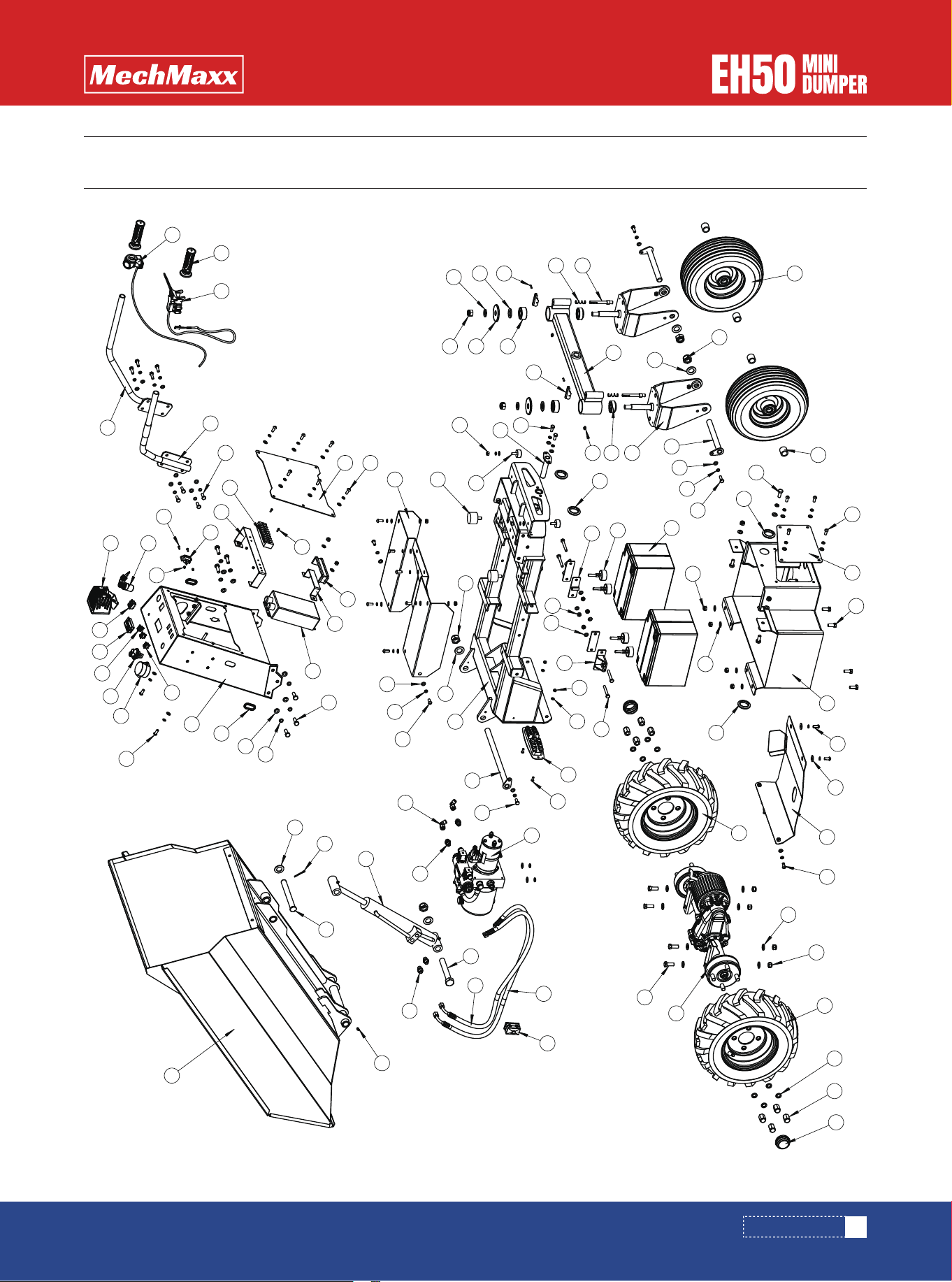
PARTS DIAGRAM
PARTS DIAGRAM
14
11
88
13
12
85
86
87
10
19
23
17
72
68
69
16
91
20
22
24
18
65
90
89
21
25
65
64
92
15
6
73
54
67
60
52
57
53
53
51
58
91
48
50
65
79
70
35
82
81
84
40
41
37
39
38
31
33
27
77
36
78
34
29
32
78
42
28
30
70
44
72
43
46
45
47
56
69
70
68
2
73
75
8
76
74
64
65
26
62
61
9
83
7
71
4
69
66
3
80
1
5
9
63
55
70
93
70
49
70
80
82
9
59

20
www.mechmaxx.com
PARTS LIST
PARTS LIST
REF DESCRIPTION QTY
1
2
3
4
5
6
7
8
9
10
11
12
13
14
15
16
17
18
19
20
21
22
23
24
25
26
27
28
29
Frame Weldment
Dump Shaft Weldment
Flat Press Plate Weldment
U-shaped Press Plate Weldment
Rubber Shock Absorber Pad
Dump Buffer Block
Rubber Foot Pad M8 L50
Work Light
Wire Protection Ring Ø35
Drive Axle
Hub Nut M14
16×6.5-8 Chevron Tire (Right)
16×6.5-8 Chevron Tire (Left)
Axle End Cap
Large Steering Axle Weldment
Steering Bracket Weldment
Caster Shaft Weldment
Stamped End Cap
Caster Spacer Sleeve
Inner Pin Shaft
Center Cam Plate
Pin Compression Spring
13×5.00-6 Wheel
Double-row Angular Contact Bearing
Tapered Roller Bearing
32Ah 12V Battery
Control Console Weldment
Wiring Board Weldment
Controller Retaining Plate
1
1
2
2
2
2
4
1
4
1
8
1
1
2
1
2
2
2
4
2
2
2
2
2
2
4
1
1
1
REF DESCRIPTION QTY
30
31
32
33
34
35
36
37
38
39
40
41
42
43
44
45
46
47
48
49
50
51
52
53
54
55
56
57
58
Control Box Cover Plate
LED Square Light
Double U-shaped Clamp Belt
Key Switch
Controller
Oval Cable Hole 20×44
Socket
Rocker Switch
6-pin Momentary Rocker Switch
3-position Rocker Switch
Battery Disconnect Switch 50A
Battery Level Gauge
TB6008 Terminal Block
Right Armrest Weldment
Left Armrest Weldment
Grip Handle
Clutch Lever with Cable
Twist Throttle with Cable
Integrated Dump Bed Weldment
Waterproof Box
Upper Link Pin
Lifting Hydraulic Cylinder
Transition Fitting
Transition Fitting
Swing Shaft Weldment
Bottom Guard Plate Weldment
Cover Plate Weldment
Power Unit Assembly
Hydraulic Hose Assembly A
1
1
1
1
1
2
1
2
1
1
1
1
1
1
1
2
1
1
1
1
1
1
2
4
1
1
1
1
1

21
www.mechmaxx.com
PARTS LIST
REF DESCRIPTION QTY
59
60
61
62
63
64
65
66
67
68
69
70
71
72
73
74
75
76
77
78
79
80
81
82
83
84
85
86
87
88
89
Hydraulic Hose Assembly B
Dual Tube Clamp ∅16
Maintenance Cover
Waterproof Base Weldment
Hex Head Bolt M20×130
Nylon Insert Thin Hex Lock Nut M20
Flat Washer 20
Nylon Insert Thin Hex Lock Nut M8
Hex Nut M8
Spring Washer 8
Flat Washer 8
Socket Head Cap Screw M8×20
Hex Head Bolt M8×60
Full-thread Hex Head Bolt M8×25
Full-thread Hex Head Bolt M8×20
Nylon Insert Thin Hex Lock Nut M6
Socket Head Cap Screw M6×16
Flat Washer 6
Nylon Insert Thin Hex Lock Nut M4
Socket Head Cap Screw M4×12
Cotter Pin 4×36
Full-thread Hex Head Bolt M10×25
Spring Washer 10
Flat Washer 10
Nylon Insert Thin Hex Lock Nut M10
Full-thread Hex Head Bolt M10×30
Full-thread Hex Head Bolt M12×30
Nylon Insert Thin Hex Lock Nut M12
Flat Washer 12
Spring Washer 14
Nylon Insert Thin Hex Lock Nut M16
1
1
1
1
1
4
7
8
2
39
45
24
4
10
3
2
2
2
4
4
1
7
9
15
6
6
4
4
8
8
2
REF DESCRIPTION QTY
90
91
92
93
Flat Washer 16
Straight Grease Fitting M6
Heavy-duty Slotted Spring Pin 4.5×16
Large Flat Washer 8
2
3
2
2