Save This Manual for Future Reference
Original Instruction
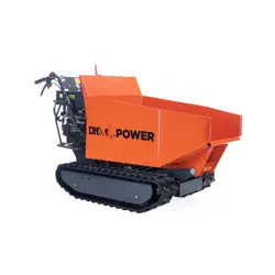
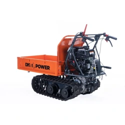
MINI TRACK DUMP CART
Operator’s Manual
MODEL NUMBER : OPD813
SERIAL NUMBER :
Both model number and serial number may be found on the main label.
You should record both of them in a safe place for future use.
FOR YOUR SAFETY
READ AND UNDERSTAND THE ENTIRE MANUAL BEFORE
OPERATING MACHINE
www.detailk2.com
SCAN THE QR CODE OR VISIT DETAILK2.COM TO
VIEW OR DOWNLOAD THE USER MANUAL.
SCANNEZ LE CODE QR OU VISITEZ
DETAILK2.COM POUR CONSULTER OU
TÉLÉCHARGER LE MANUEL D'UTILISATION.

WARRANTY
PLEASE DO NOT RETURN TO THE STORE
YOU HAVE A 1-YEAR WARRANTY AND DK2 WILL REPLACE A DEFECTIVE PART FOR FREE. CALL US AT 1 (888)
277-6960 FOR FAST WARRANTY PARTS AND QUESTIONS.
WHAT IS COVERED – 3-YEAR ENGINE AND 1-YEAR DK2 LIMITED WARRANTY INCLUDED
DK2 warrants to the original purchaser that product will be free and clear of manufacturing defects in workmanship
and materials under normal use and service for a period of one (1) year from the date of the original purchase. If
within one (1) year from the original date of purchase this product fails due to defect in material or workmanship,
DK2 will repair, replace, or supply any covered defective part at our option. DK2 POWER is 1-year parts only warranty
no labor. KOHLER® 3-year warranty is PARTS and LABOR.
Upon expiry of one (1) year, DK2 will have no further liability related to the product. DK2 does not authorize any
SERIAL NUMBERS MUST BE REGISTERED ONLINE AT WWW.DK2.COM, WARRANTY NON-TRANSFERABLE.
KOHLER® ENGINES –KOHLER® CH SERIES ENGINES 3 YR PARTS AND LABOR WARRANTY
KOHLER® ENGINES –KOHLER® SH SERIES ENGINES RESIDENTIAL 2 YR PARTS AND LABOR WARRANTY
See your KOHLER® manual for specific warranty.
DK2 – 1-year parts only, no labor. 3-year KOHLER® warranty.
THIS WARRANTY DOES NOT COVER OR APPLY TO:
(a) Damage to the product due to misuse, mishandling and abuse
(b) Improper installation, maintenance and storage
(c) Expendable parts such as nuts and bolts, pins and springs, wiring and switch components, hydraulic hoses and
fittings, cutting teeth, cutting chains, cutting blades, throttles, belts and tires.
(d) Normal wear and tear
(e) Consequential damage & incidental damages such as damage to persons or property
PROCEDURE FOR OUTDOOR POWER EQUIPMENT WARRANTY
Within the one (1) year warranty period, the purchaser of the product can CALL 1 (888) 277-6960 or contact us
on www.DK2.com. Notify us of the claimed defect and provide proof of original purchase. At this time the validity
of the claim will be determined, and if approved replacement parts will be issued. No returned product will be
accepted under warranty unless accompanied by an RGA# issued by DK2.
DAMAGED FREIGHT
Damage to your product caused by freight mishandling is NOT covered under warranty. If your freight arrives
damaged, REFUSE it. Inspect your product when it arrives, otherwise if you accept it, you will be responsible for
filing any freight claims with the delivery company. DK2 warranty excludes damage to product.
RETURNS BEFORE GAS AND OIL
Follow the return policy from the retailer you purchased the equipment from.
RESOLUTION FOR A DEFECTIVE PRODUCT AFTER GAS AND OIL HAS BEEN ADDED.
Call us at 1 (888) 277-6960 between 8am-4pm Monday to Friday EST.

DO NOT RETURN THIS
PRODUCT TO THE STORE WITH
GAS AND OIL IN IT.
If you have assembly or other product questions,
please contact our technical customer service team by
email or phone for assistance.
STOP
1 (888) 277-6960
detailk2.com/contact-us
MINI TRACK DUMP CART
2
GB
TABLE OF CONTENTS
ENVIRONMENTAL
Specification
INTRODUCTION
Introduction 2
Specifications 2
Symbols 3
Safety 4
General Safety Rules 4
Specific Safety Rules 6
Unpacking The Container 7
Contents Supplied 8
Assembly 9
Know your Machine 10
Features & Controls 10
Operation 10
Maintenance 14
Storage 18
Trouble Shooting 19
Parts Diagram 20
Parts Lists 21
Carefully read through this entire
operator’s manual before using this
unit. Take special care to heed the
cautions and warnings.
Recycle unwanted materials instead
of disposing of them as waste. All
tools, hoses and packaging should
be resorted, taken to the local
recycling center and disposed of in
an environment-friendly safe way.
The four-speed gearbox, three forward and
one reverse, lies at the heart of the unit. It is
oversized so as to manage safely the huge
torques generated by the engine. Thanks to
its efficient reduction gearing, it is capable of
moving around in every situation and bearing
any load.
The Engine manufacturer is responsible
for all engine-related issues with regards to
performance, power rating, specifications,
warranty and service. Please refer to the
Engine Manufacturer’s owner’s/operator’s
manual
, packed separately with your unit, for
more information.
Item No.
Engine KOHLER CH270
Net Power 7hp (5.2kw)
OPD813
Transmission 3F+1R
Load Capacity 660 lb
Box Length 38.5-40.9 in
Box Width 23.6-33.8 in
Box Depth 8.0 in
Track Width 7.0 in
Sound power level
101 dB(A)
k=2 dB(A)
Sound pressure level 82.2 dB(A)
k=2 dB(A)
Weight 401 lb
Your new dump cart will more than satisfy
your expectations. It has been
manufac t ure d under str i ngent quality
standards to meet superior performance
criteria. You will find it easy and safe to
operate, and with proper care, it will give you
many years of dependable service.
MINI TRACK DUMP CART
3
GB
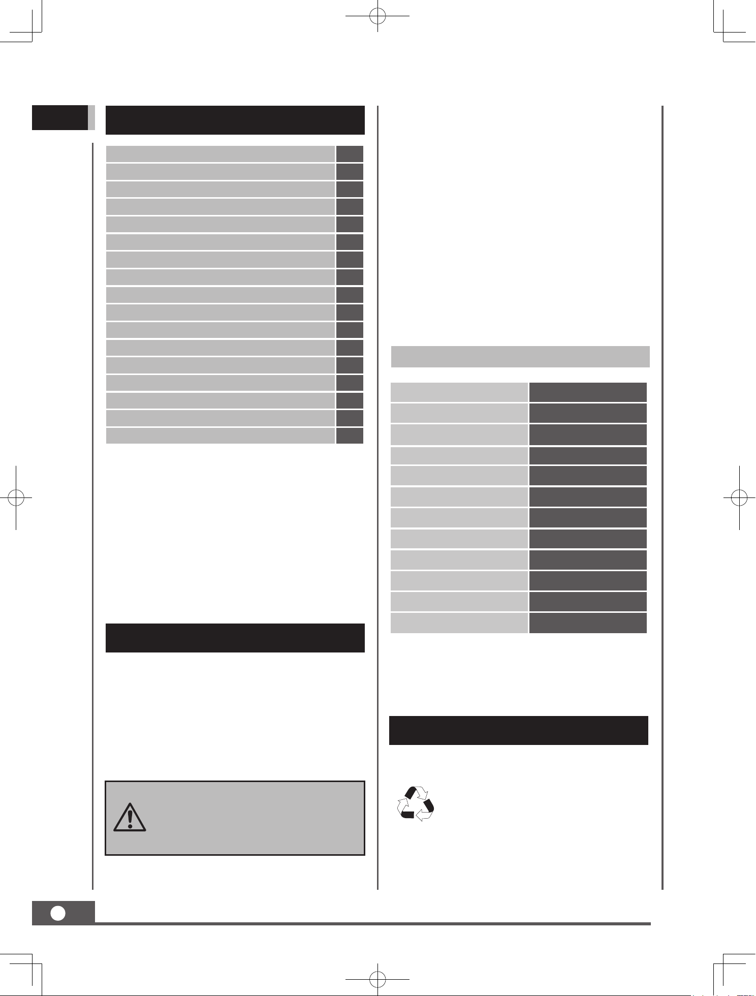
SYMBOLS
The rating plate on your ma chine may
show symbols. These represent important
information about the product or instructions
on its use.
Read these instructions carefully.
Wear eye protection.
Wear hearing protection.
Wear protective gloves.
Wear safety footwear.
D o no t remove or tamp e r
with the protection and safety
devices.
No smoking, sparks, or flames
Do not touch parts that are hot
from operation. Serious burns
may result.
Keep your hands clear from all
rotating parts.
Never start or run the engine
inside a closed area.
Do not operate on slopes with
angle over 20° or tip loading at
an inclined position.
Be awa r e , obje c t s m a y be
thrown while in use.
The exhaust fumes are dangerous,
containing carbon monoxide.
Staying in the environment can
lead to unconsciousness and
death.
Always turn o the engine
before starting maintenance.
Keep children and bystanders
o and away.

MINI TRACK DUMP CART
4
GB
SAFETY
General Safety Rules
Protect eyes, face, and head from objects that
may be thrown from the unit. Always wear
safety goggles or safety glasses with side
shields when operating.
Wear appropriate hearing protection.
Always keep hands and feet away from all
moving parts during operation. Moving parts
can cut or crush body parts.
Always keep hands and feet away from all
pinch points.
Do n ot touch part s that might be h ot
from operation. Allow parts to cool before
attempting to maintain, adjust, or service.
Stay alert, watch what you are doing, and use
common sense when operating the machine.
Do not overreach. Do not operate the machine
while barefoot or when wearing sandals or
similar lightweight footwear. Wear protective
footwear that
will protect your feet and
improve your footing on slippery surfaces.
Keep proper footing and balance at all times.
This enables better control of the machine in
unexpected situations.
Inspect Your Machine
Check your machine before starting it. Keep
guards in place and in working order. Make
sure all nuts, bolts, etc., are securely tightened.
Never operate the machine when it is in need
of repair or is in poor mechanical condition.
Replace damaged, missing, or failed parts
before using it. Check for fuel leaks. Keep the
machine in safe working condition.
Do not use the machine if the engine’s switch
does not turn o the engine when running.
Any gasoline powered mach
ine that can’t be
controlled with the engine switch is dangerous
and must be replaced.
Regularly check to see that keys and adjusting
wrenches are removed from the machine area
before starting it. A wrench or a key that is
left attached to a rotating part of the machine
may result in personal injury.
Avoid accidental starting. Be sure the engine’s
switch is off before transporting the machine
or performing any maintenance or service
Understand Your Machine
Read this manual and labels aixed to the
machine to understand its limitations and
potential hazards.
Be thoroughly familiar with the controls and
their proper operation. Know how to stop the
machine and disengage the controls quickly.
Make sure to read and understand all the
instructions and safety precautions as outlined
in the Engin
e Manufacturer’s manual packed
separately with your unit. Do not attempt to
operate the machine until you fully understand
how to properly operate and maintain the
engine and know how to avoid accidental
injuries and/or property damage.
If the unit is to be used by someone other than
original purchaser, or is to be loaned, rented,
or sold, always provide this manual and any
needed safety training before operation.
The user can prevent and is responsible
for accidents or injuries that may occur to
themselves, to other people, or to property.
Do not force the machine beyond it
s limits.
Use the correct machine for your application.
Personal Safety
Do not permit children to operate this machine
at any time.
Keep children, pets, and other people not
using the unit away from the work area. Be
alert and shut o the unit if anyone enters
work area. Keep children under the watchful
care of a responsible adult.
Do not operate the machine while under the
influence of drugs, alcohol, or any medication
that could aect your ability to use it properly.
Dress properly: Wear long, heavy pants, work
boots, and work gloves. Do not wear loose
clothing, short pants, or jewelry of any kind.
Secure long hair so it is above shoulder level.
Keep your hair, clot
hing, and gloves away
from moving parts. Loose clothes, jewelry, or
long hair can be caught in moving parts.
MINI TRACK DUMP CART
5
GB
on the unit. Transporting or performing
maintenance or service on a machine with its
switch on invites accidents.
If t he machine sh ou ld s ta rt t o vi br at e
abnormally, stop the engine (motor) and
check immediately for the cause. Vibration is
generally a warning sign of trouble.
Engine Safety
This machine is equipped with an internal
combustion engine. Do not use on, or near,
forest-covered or brush-covered land unless
the exhaust system is equipped with a spark
arrester meeting applicable local, state, or
federal laws.
In the state of California, a spark arrester is
required by law. Other state
s have similar laws.
A spark arrester, if used, must be maintained
in eective working order by the operator.
Never start or run the engine inside a closed
area. The exhaust fumes are dangerous,
containing carbon monoxide, an odorless and
deadly gas. Operate this unit only in a well-
ventilated outdoor area.
Do not tamper with the engine in an eort to
get it to run at higher speeds. The maximum
engine speed is preset by the manufacturer
and is within safety limits. See engine manual.
Keep a Class B fi re extinguisher on hand
when operating this machine in dry areas as a
precautionary measure.
Fuel Safety
Fuel is highly flammable, and its vapors can
explode if ignited. Take pr
ecautions when
using to reduce the chance of serious personal
injury.
When refilling or draining the fuel tank, use
an approved fuel storage container while in
a clean, well-ventilated outdoor area. While
adding fuel or operating the unit, do not
smoke, and stay away from sparks, open
flames, or other sources of ignition near the
area of operation. Never fi ll the fuel tank
indoors.
To avoid sparking or arcing, keep grounded
conductive objects – such as tools – away
from exposed, live electrical parts and
conn
ections. These events could ignite fumes
or vapors.
Always stop the engine and allow it to cool
before filling the fuel tank. Never remove
the cap of the fuel tank or add fuel while the
engine is running or when the engine is hot.
Do not operate the machine with known leaks
in the fuel system.
Loosen the fuel tank cap slowly to relieve any
pressure in the tank.
Never overfill the fuel tank. Because engine
heat can cause fuel to expand, never fill the
tank to more than 1/2” below the bottom of
the filler neck. This will provide space for fuel
expansion.
Replace all fuel tan
k and container caps
securely and wipe up spilled fuel. Never
operate the unit without the fuel cap securely
in place.
Avoid creating a source of ignition for spilled
fuel. If fuel is spilled, do not attempt to start
the engine. Instead, move the machine away
from the area of spillage and avoid creating
any source of ignition until fuel vapors have
dissipated.
When fuel is spilled on yourself or your
clothes, wash your skin and change clothes
immediately.
Store fuel in containers specifically designed
and approved for fuel storage.
Store
fuel in a cool, well-ventilated area, safely
away from sparks, open flames, or other
sources of ignition.
Never store fuel – or a machine with fuel in
the tank – inside a building where fumes may
reach a spark, open flame, or any other source
of ignition (such as a water heater, furnace, or
clothes dryer). Allow the engine to cool before
storing in any enclosure.
MINI TRACK DUMP CART
6
GB
On soft ground, drive at the first forward/
reverse gear. Do not rapidly accelerate, turn
sharply or stop.
Pay the utmost attention when working on
frozen ground, as the machine may tend to
skid.
Do not operate the machine in confined areas
where there may be a risk of crushing the
operator between the machine and another
object.
Never operate the machine on slopes where
angle is over 20°.
When operating on a slope, whether moving
forward or in reverse, always make certain that
the weight is evenly balanced. Always operate
the machine straight up or down slopes, never
drive sideways or across
the slope. Do not
shift gears on slopes.
When dumping the contents of the hopper,
the center of gravity will change continuously
and the ground conditions will be essential for
the stability of the machine. Use extra caution
and control when dumping the hopper on
unstable ground, such as wet clay or soil.
Specific Safety Rules
Thoroughly inspect the area to be worked.
Keep the working area clean and free of debris
to prevent tripping. Operate on flat, level
ground.
Never place any part of your body where
it would be in danger if movement should
occur during assembly, installation, operation,
maintenance, repair, or relocation.
Keep all bystanders, children, and pets at least
905in away. If you are approached, stop the
unit immediately.
Do not mount anything on the hopper and
never carry passengers.
Never park the machine in a place with
unstabl e g round th a t c oul d g i ve way ,
particularly when it is full.
Disengage clutch lever before starting the
engine.
Start the engine carefully according to
i
nstructions and with feet away from the
moving parts.
Never leave the operating position when the
engine is running.
Always hold the unit with both hands when
operating. Keep a firm grip on the handlebars.
Be aware that the machine may unexpectedly
bounce upward or jump forward if the
machine should strike buried obstacles such
as large rocks or roots.
Walk, never run with the machine.
Do not overload the machine capacity.
Always drive at a safe speed, and adjust the
speed to the slope of the land, the surface
conditions of the road, and the weight of the
load.
Use extreme caution when in reverse or
pulling the machine towards you.
Exercise extreme caution when operating on
or crossing gravel drives, walks, or roads. Stay
alert for hidden hazards or trac.
MINI TRACK DUMP CART
7
GB
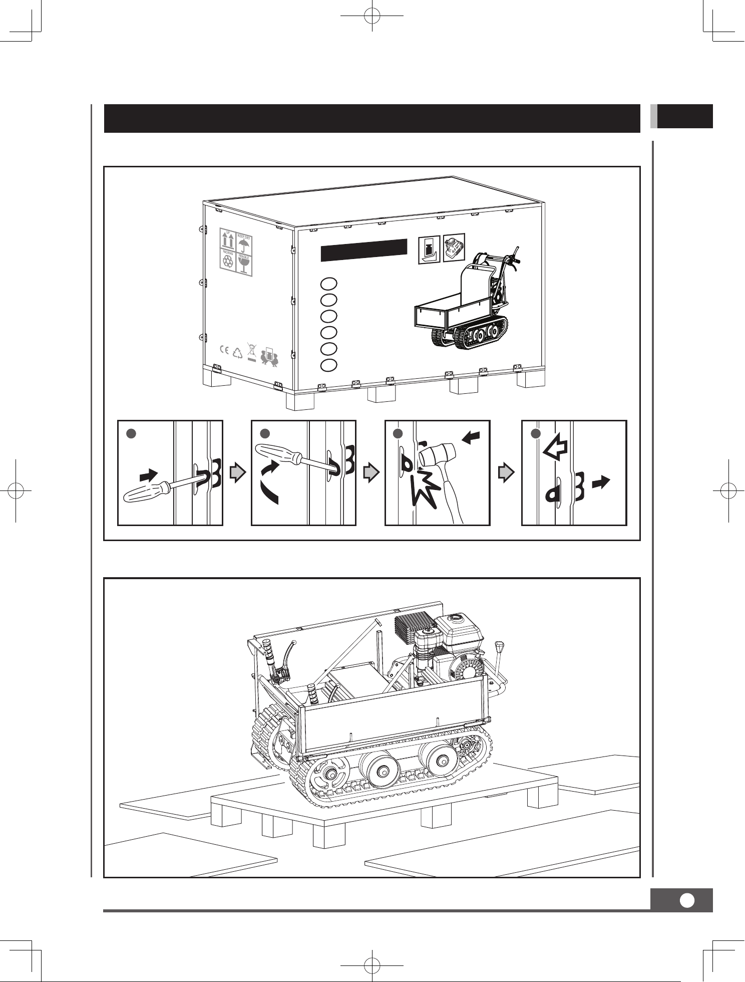
UNPACKING THE CONTAINER
Use the screwdriver and hammer to open all the side locks.
Remove all the plywood plates, and remove all the loose parts on the bottom pallets.
1 2 3 4
Mini Track Dumper
GB
MiniraupendumperDE
Mini-DumperCZ
MinitrasporterIT
ТранспортерRU
Brouette motorisée sur chenillesFR
MINI TRACK DUMP CART
8
GB
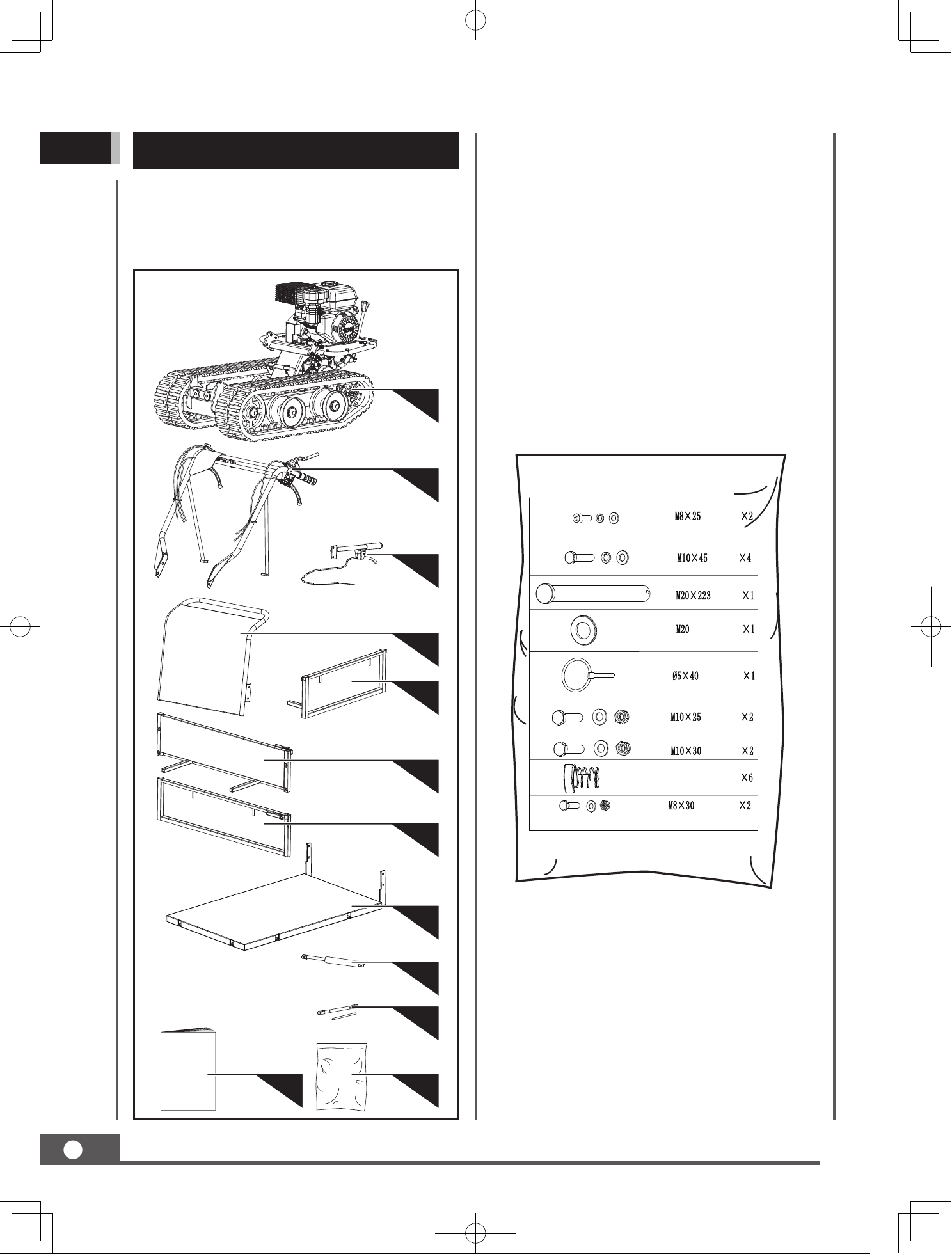
CONTENTS SUPPLIED
12
8
9
10
7
6
5
2
3
4
1
11
1. Main Frame
2. Handlebar Assembly
3. Tipping Handle
4. Engine Guard
5. Panel (Rear)
6. Extendable Left Side
7. Extendable Right Side
8. Panel (Bottom)
9. Gas Spring (Optional)
10. Tools for Spark Plug Assembly
11. Operator’s Manual & Engine Manual
12. Hardware Bag, Including
The dump cart comes partially assembled and
is shipped in a carefully packed package.
After all the parts have been removed from
the package, you should have:
MINI TRACK DUMP CART
9
GB
Following the assembly directions below, you
will assemble the machine in a few minutes.
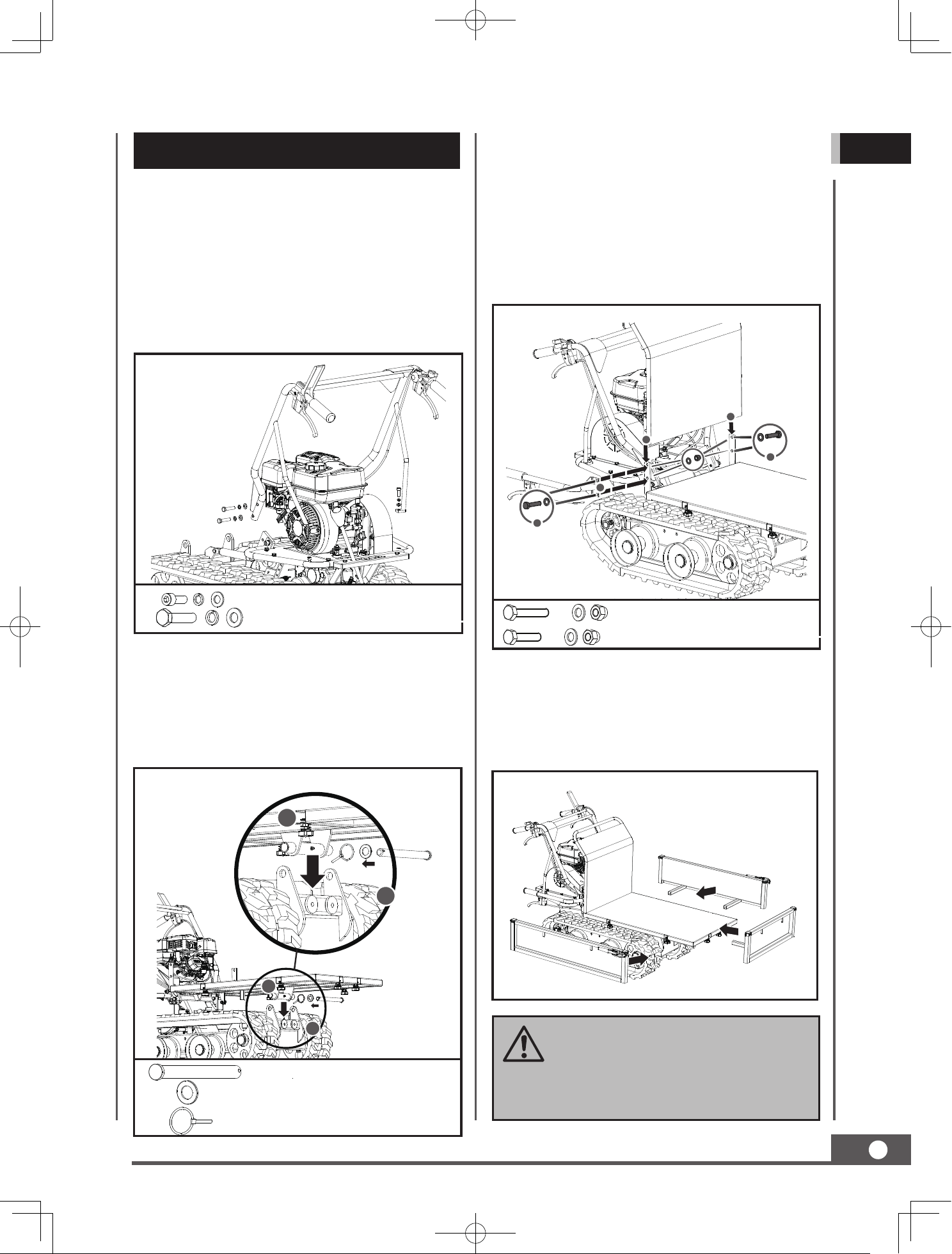
Handlebar Assembly
ASSEMBLY
Align the holes of the handlebar with the mount
bracket and secure each with a spring washer,
flat washer and a M10x20 bolt . Fasten each
handlebar support onto the engine deck with a
spring washer, flat washer and a M8x25 hex bolt.
Panel (Bottom)
Position the bottom panel inside the mounting
bracket. Align the holes with the mounting
bracket. Insert a long pin through holes and
secure each side with a flat washer and cotter pin.
F
Tipping Handle & Engine Guard
M10 X 25 X 2
M10 X 30 X 2
M8X25 X 2
M10X45 X 4
Place the engine guard inside the mounting
bracket and align with the mounting bracket
holes. Secure panel left side with two M8x30
hex bolts, four washers and two nuts. Mount
the tipping handle on panel right side. Align
holes and fasten with two M8x35 hex bolts,
four washers and two nuts.
Panel (Rear) & Extendable Left/Right Side
Insert the extendable sides into mounting slots
located on the bottom panel and fasten each
at the bottom with two L pins and locknuts.
1
2
2
1
3
M8 X 25
3
M8 X 30
2
1
1
M20X223 X 1
M20 X 1
Ø5X40 X 1
OIL HAS BEEN DRA INE D FOR
SHIPPING. Failure to fill engine
sump with oil before starting
engine will result in permanent
damage and void engine warranty.
MINI TRACK DUMP CART
10
GB
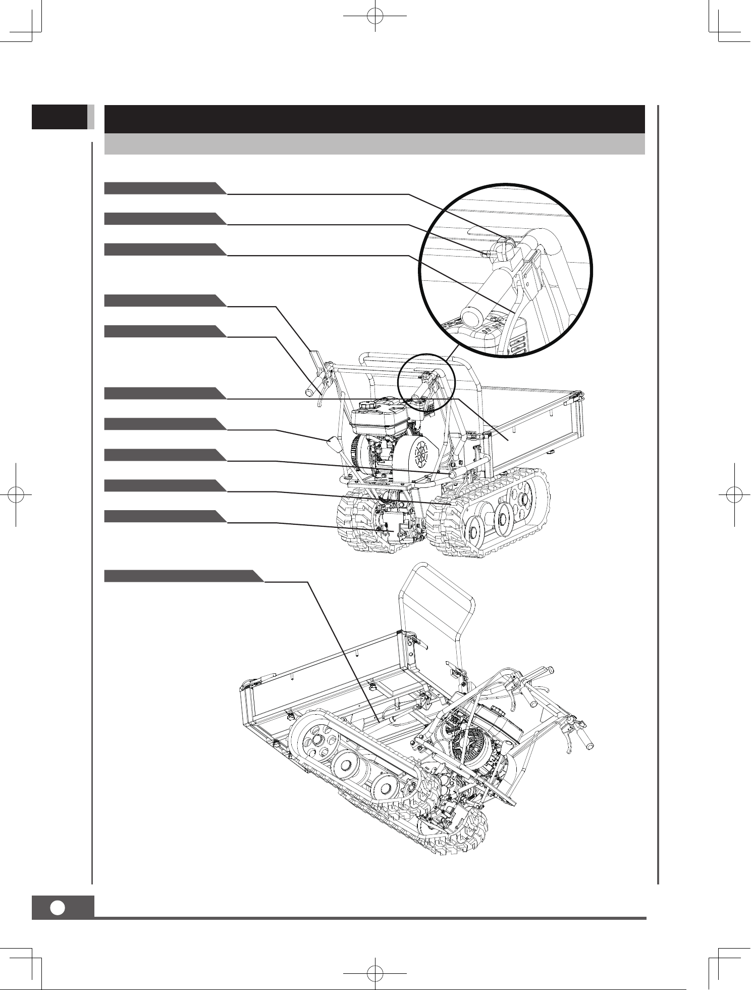
KNOW YOUR MACHINE
Features and Controls
Throttle Control
Engine Switch
Right Steering Lever
Clutch Control Lever
Left Steering Lever
Hopper
Track
Tipping Handle
Gearbox
Gear Selection Lever
Gas Spring Assistance (Optional)
MINI TRACK DUMP CART
11
GB
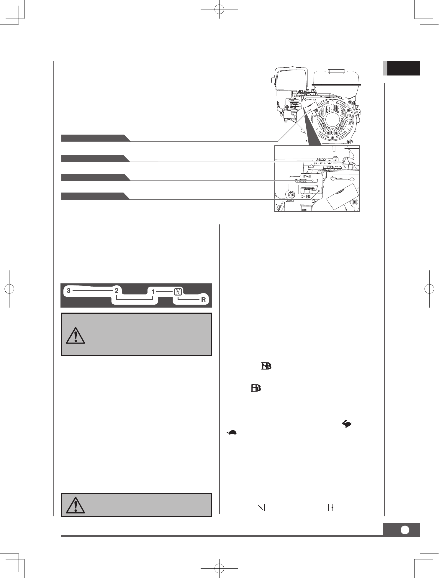
Recoil Starter Handle
Choke Control
Fuel Shut-O Valve
Throttle Control
Always release the clutch control
lever before changing speeds.
Failur e to do s o w il l resul t in
damage to the power trackbarrow.
Operate the steering levers only at
a reduced speed.
The gas spring assistance provides support
when lifting and lowering the hopper.
Gas Spring Assistance (Optional)Gear Selection Lever
The gear selection lever has 4 positions: 3
forward speeds and 1 reverse. To change
speeds, move the speed shift lever to the
desired position. The lever locks in a notch at
each speed selection.
Slower speeds are for heavier loads, while
faster speeds are for transporting light loads
or an empty hopper. It is recommended that
you use a slower speed until you are familiar
with the operation of the power trackbarrow.
If the engine slows down under a load or the
tracks slip, shift the machine into a lower gear.
If the front of the machine rides up, shift
the machine into a lower gear
. If the front
continues to ride up, lift up on the handles.
Operate the lever to turn left/right.
Left/Right Steering Lever
Engine On/O Switch
The engine switch has two positions. OFF -
engine will not start or run. ON - engine will
start and run.
Recoil Starter Handle
The recoil starter handle is used to start the
engine.
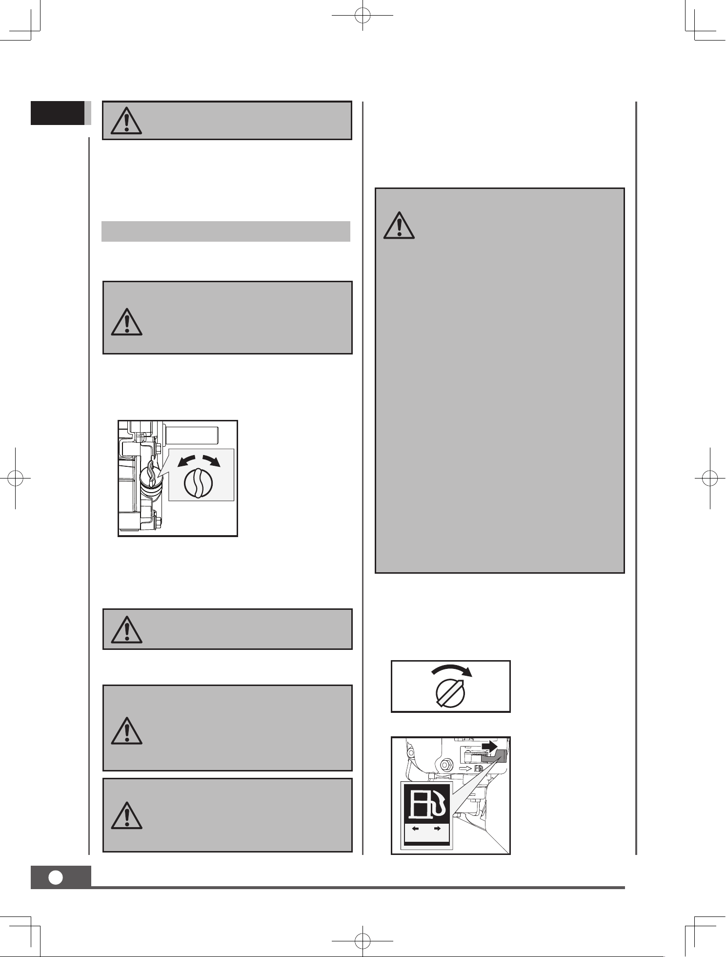
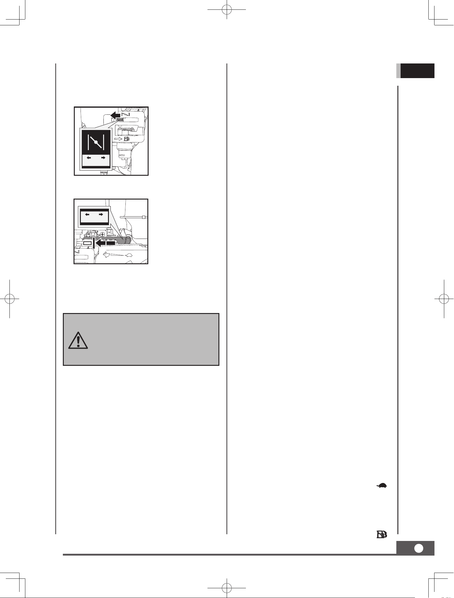
Fuel Shut-O Valve
The fuel shut-o has two positions:
CLOSED (
) - Use this position to service,
transport, or to store the unit.
OPEN (
) - Use this position to run the unit.
Throttle Control
The throttle control regulates the speed of the
engine, and moves between FAST
, SLOW
, and STOP positions.
The throttle control will shut o the engine
when it is moved to the STOP position.
Choke Control
The choke control is used to choke the
carburetor and assist in starting the engine.
The choke control slides between the CHOKE
CLOSED
and CHOKE OPEN positions.
MINI TRACK DUMP CART
Make sure the dump cart is on a flat, level
surface.
12
GB
Operation
The engine is shipped without oil. Do
not start the engine before adding oil.
Please refer to your engine manual
for the proper grade of oil to add.
DO NOT OVERFILL. Check engine
oil level daily and add as needed.
Gasoline is highly flammable and
explosive. You can be burned or
seriously injured when handling fuel.
Use extreme care when handling
gasoline.
Fill the fuel tank outdoors, never
indoors. Gasoline vapors can ignite
if they collect inside an enclosure.
Explosion can result.
IMPORTANT: DO NOT OVERFILL!
This equipment and/or its engine
may
include evaporative emissions
c o n t r o l s y s t e m c o m p o nen t s ,
r e q u i red t o m e e t E P A a n d /
or CARB regulations, that will
only function properly when the
fuel tank has been filled to the
recommended level. Overfilling
may cause permanent da mage
to evaporative emissions control
system components. Filling to
the recommended level ensures
a vapor gap required to allow for
fuel expansion. Pay close attention
while filling the fuel tank to ensure
that the recommended fuel level
inside the tank is not exceeded. Use
a portable gasoline container with
an appropriately sized dispensing
spout when filling the tank. Do not
use a funnel or other device that
obstructs the view of the tank filling
process.
Never use choke to stop engine.
Clutch Control Lever
Squeeze the control lever, clutch engaged.
Release the lever, clutch disengaged.
Open the fuel shut-o valve.
Move the engine switch to the ON position.
Using a funnel, add oil up to the FULL mark
on the dipstick. (See engine manual for oil
capacity, oil recommendation, and location
of fill cap.)
Reinstall the fuel cap and tighten. Always
clean up spilled fuel.
Remove the oil fill cap/dipstick to add oil.
1.
2.
1.
3.
3.
2.
Add Oil To Engine
Add Gasoline To Engine
CLOSEDOPEN
Starting Engine
ONOFF
ONOFF
The engine must be o and allowed to cool
at least two minutes before adding fuel.
Remove the fuel filler cap and fill the tank.
(See engine manual for fuel capacity, fuel
recommendation, and location of fuel cap.)
1.
2.
MINI TRACK DUMP CART
The dump cart has a maximum load capacity
of 660 LBS. However, it is advisable to assess
the load and adjust it according to the ground
on which the machine will be used.
Even though the unit has rubber tracks,
remember to be careful when working in
adverse weather conditions (ice, heavy rain
and snow) or on types of ground that could
make the dump cart unstable.
The dump cart has the steering levers on the
handlebars, which makes steering very easy.
To turn right or left, simply pull the
corresponding right or left steering lever.
Engage the required gear and slowly squeeze
the clutch control lever. If the gear does not
engage immediately, slowly release the clutch
lever and try again. In this way the power
trackbarrow will start moving.
13
GB
Rapid retraction of the starter cord
(kickback) will pull your handand arm
toward the engine faster than you
can let go. Broken bones, fractures,
bruises, or sprains could result.
SLOWFAST
OPENCLOSED
Operating
After the engine warms up, move the throttle
lever to accelerate engine speed.
The sensitivity of the steering increases in
proportion to the speed of the machine and
the load. With an empty machine, a light
pressure on the lever is all that is needed to
turn. When the machine is fully loaded, more
pressure is required.
It is, therefore, advisable to cover uneven or
rough terrain using a low gear, and to take
extra precautions. In such situations, the
machine should be kept in low gear for the
entire stretch.
Avoid sharp turns and frequent changes
of
direction while driving on rough, hard terrains
full of sharp, uneven points with a high degree
of friction.
Please note that as this is a track vehicle, it is
subject to a considerable pitching movement
when passing over bumps, holes and steps.
When the clutch control lever is released, the
machine will stop and brake automatically.
If the machine is stopped on a steep slope, a
wedge should be placed against one of the
tracks.
Idle Speed
Set the throttle control lever to the SLOW
position to reduce stress on the engine when
work is not being performed. Lowering the
engi
ne speed will help extend the life of the
engine, as well as conserve fuel and reduce
noise level.
STOP ENGINE
To stop the engine in an emergency, simply turn
the engine switch to the OFF position. Under
normal conditions, use the following procedure:
Move the choke lever to the CLOSED
position.
If the engine is hot, closing the choke is not
necessary.
Move the throttle lever slightly to the FAST
speed.
Pull the recoil starter until the engine starts.
Return the recoil to the home position after
each
pull. Repeat the steps as needed. Once
engine has started, set the throttle to the
FAST position before you operate the unit.
Move the throttle lever to the SLOW (
)
position.
Let the engine idle for one or two minutes.
Turn the engine switch to the OFF position.
Turn the fuel valve lever to the OFF (
)
position.
3.
4.
5.
1.
2.
3.
4.
SLOWFAST
OPENCLOSED
Inspect the general condition of the dump
cart. Check for loose screws, misalignment
or binding of moving parts, cracked or
broken parts, and any other condition that
may aect its safe operation.
Maintaining your dump cart will ensure long
life to the machine and its components.
MINI TRACK DUMP CART
14
GB
MAINTENANCE
Never use a “pressure washer” to
clean your unit. Water can penetrate
tight areas of the machine and its
transmission case and cause damage
to spindles, gears, bearings, or the
engine. The use of pressure washers
will result in shortened life and
reduce serviceability.
S u dden s t o p p ing a t a hig h
speed under a heavy load is not
recommended. Engine damage may
result.
Do not move the choke control to
CLOSE to stop the engine. Backfire
or engine damage may occur.
1.
1.
1.
2.
2.
3.
3.
4.
5.
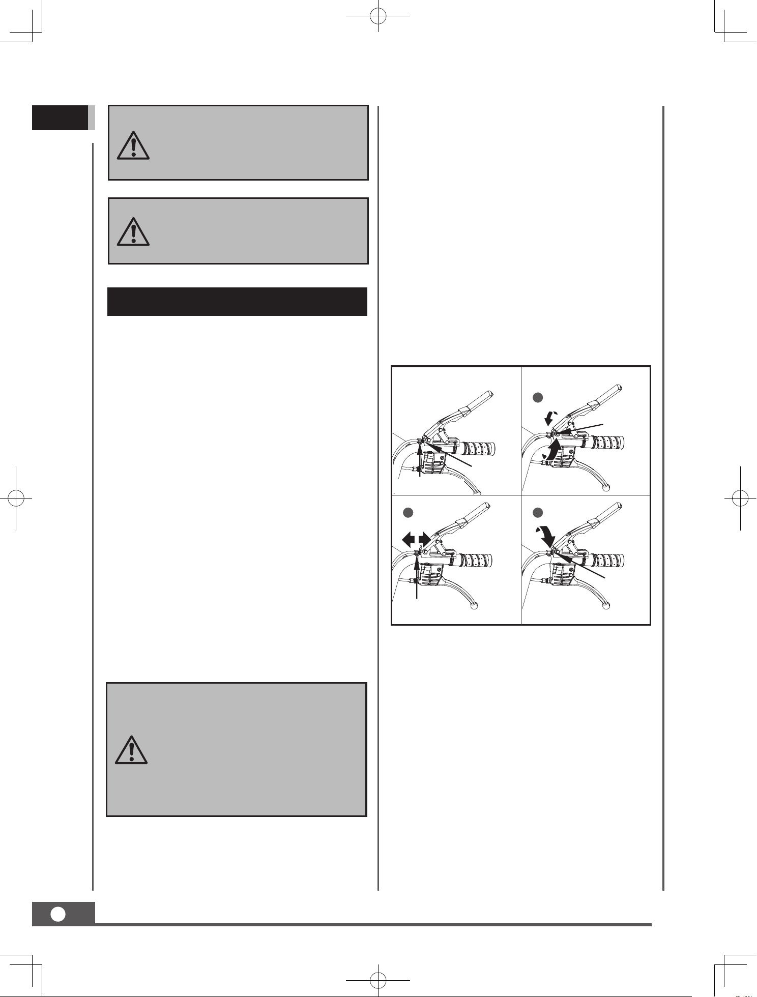
Adjusting Clutch
When the clutch begins to show wear, the
handle reach will become wider, making it
more difficult to reach. Follow these steps
to return the clutch lever back to its original
position.
Preventive Maintenance
Jam Nut
Adjustment Nut
Adjustment Nut
Jam Nut
Jam Nut
1
2 3
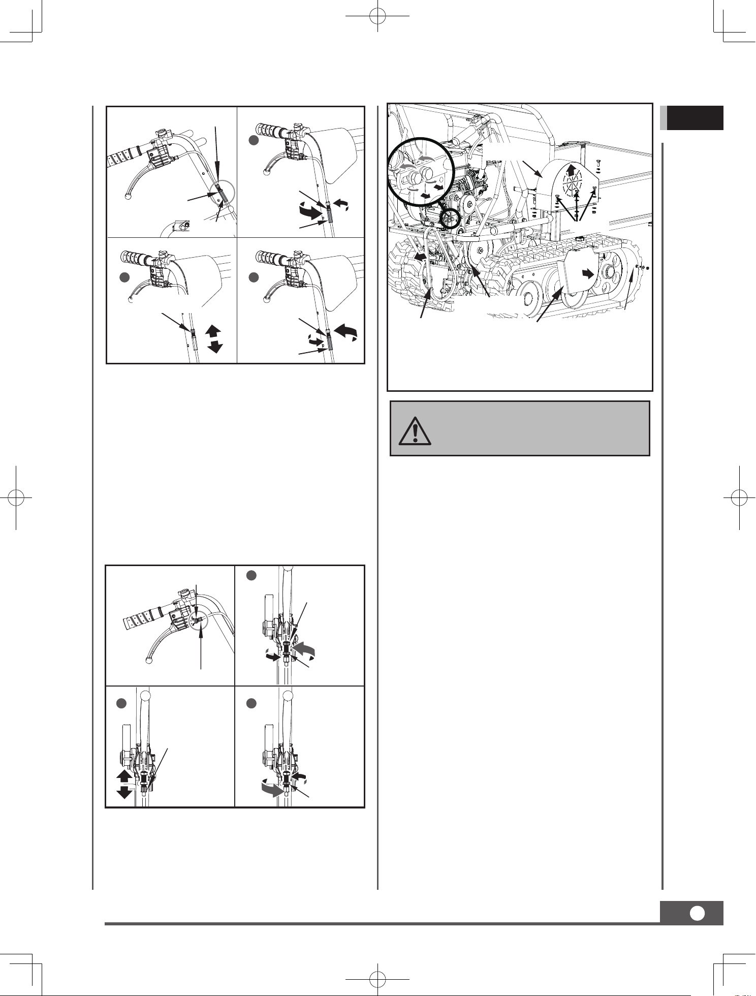
Adjusting Steering
If steering becomes dicult to engage, follow
these steps to adjust the cable tension.
Turn off the engine and disengage all
command levers. The engine must be cool.
Keep the engine’s throttle lever in its SLOW
position and remove the spark plug wire
from the spark plug and secure.
Use a soft brush, vacuum or compressed
air to remove all contaminants from the
machine. Then use high quality light oil to
lubricate all moving parts.
Check the spark plug wire regularly for
signs of wear, and replace when needed.
Loosen the jam nut by turning it counter
clockwise with 0.4 in wrench.
Tighten or loosen the cable by turning the
cable adjustment nut clockwise or counter
clockwise with 0.4 in wrench until you
have reached your required tightness.
Once tightness is set, return the jam nut
against th
e handle to hold the cable in
place.
Loosen the jam nut by turning it counter
clockwise with 0.4 in wrench.
2.
3.
Tighten or loosen the cable by turning the
cable adjustment nut clockwise or counter
clockwise with 0.4 in wrench until you
have reached your required tightness.
Once tightness is set, return the jam nut
against the handle to hold the cable in place.
MINI TRACK DUMP CART
15
GB
2.
1.
3.
Loosen the jam nut by turning it counter
clockwise with 0.47 in wrench.
Tighten or loosen the cable by turning the
cable adjustment nut clockwise or counter
clockwise with 0.4 in wrench until you
have reached your required tightness.
Once tightness is set, return the jam nut
against the handle to hold the cable in place.
1
Jam Nut
Lock Nut
2 3
Jam Nut
Adjustment Nut
Adjustment Nut
Jam Nut
1
Jam Nut
Jam Nut
Lock Nut
Lock Nut
2
Adjustment Nut
3
Jam Nut
Adjustment Nut
Lock Nut
If the above adjustment does not create
enough cable tension, follow the steps below:
Replacing Drive Belt
Remove belt covers as shown and pull out the
belt.
You may need to loosen the belt
guide bracket and slide back before
removing belt.
Lubrication
General Lubrication
Lightly lubricate all moving parts of the
machine at end of the season or every 25
operating hours.
Gearbox Lubrication
The gearbox is pre-lubricated and sealed at the
factory. Unless there is evidence of leakage or
service has been performed on the gearbox, no
additional lubricate should be required until 50
hours use.
After first 50 hours use, change all the gear oil.
Capacity is 1.5L.
For future use, check the oil level after every
50 hours of use. If you remove the
oil level plug
and no oil flows out, please add oil and then
screw the oil level plug.
Ge ar o il GL-5 o r GL-6 , SA E80W-90 i s
recommended. Do not use synthetic oil.
When replacing gear oil, the engine must be
stopped and still warm. Unscrew the filter cap
and the drain plug. When oil is drained, replace
the drain plug, fill up with fresh oil, and then
replace the filter cap.
M8×20
M6×20
Belt Cover for Gearbox Pulley
Gearbox Pulley
Drive Belt
Belt Cover
MINI TRACK DUMP CART
16
GB
Do not over-tighten your track.
The adjustment of the track and
the brakes are linked. The braking
power will lessen the more the track
is tightened.
If the adjustment bolt has no more
adjustment left, the tracks may have
to be replaced.
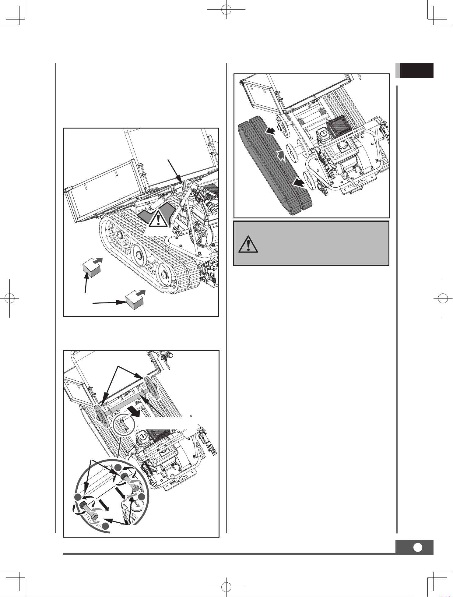
Replacing Tracks
Check the condition of the tracks periodically.
If any track is cracked or frayed, it should be
replaced as soon as convenient.
2.
3.
2.
4.
3.
5.
1.
1.
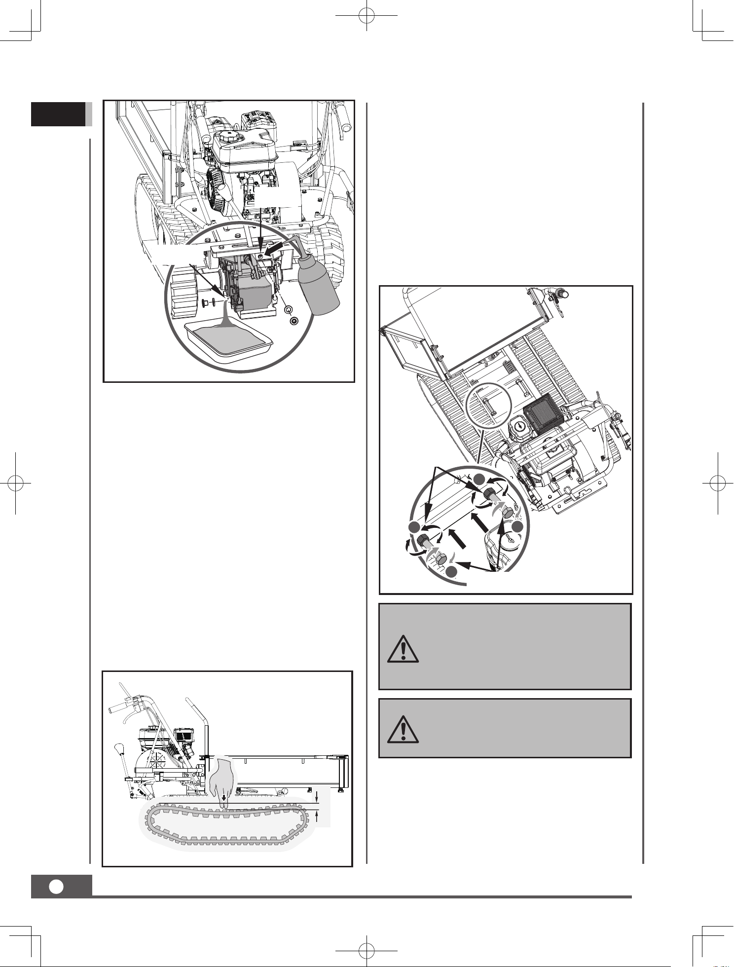
Tightening Tracks
With use, tracks tend to loosen. When
operating with loose tracks, they tend to slip
over the driving wheel causing it to jump its
housing, thus damaging wear to the housing.
To check track tightness, proceed as follows.
If the distance is greater, proceed as follows.
Use the tipping handle to tip the hopper
and set it on blocks or supports rated for
the weight of the box.
Loosen locknut A.
Tighten bolt B until the correct tightness is
restored.
Secure bolt B by tightening locknut A
thoroughly.
Return the hopper to its original position.
Set the machine on a flat surface with
compact ground, or on asphalt or pavement.
Lift the machine and set it on blocks or
supports rated for the weight of the machine
so that the tracks are approximately 4” off
the ground.
Measure the track midline vs. the horizontal
line. The reading must not be more than
0.4 in~0.6 in.
A
A
Adjusting Bolt
Jam Nut
B
B
Oil Outlet
Oil Filler
0.4 in ~ 0.6 in
MINI TRACK DUMP CART
17
GB
When removing or installing the
tracks, be careful not to get your
fingers caught between the track
and pulley.
Lift up the hopper and insert a support rod
for safety purposes.
Lift the machine and set it on blocks
or supports rate d f or the wei ght of
the m a c h i ne s o t h a t t h e t r ack s a r e
approximately 4” o the ground.
Loosen the adjusting bolts and pull the
steering wheel axle toward the engine, then
track will be loosen.
Engine Maintenance
Refer to the Engine Manual included in
your unit for the information on engine
maintenance. Your engine manual provides
detailed information and a maintenance
schedule for performing the tasks.
Pull out the whole track.
2.
3.
4.
1.
A
A
Adjusting Bolt
Jam Nut
B
Steering Wheel Axle
Steering Wheel
B
Danger Area
Support Object
Support Rod
If the dump cart will not be used for a period
longer than 30 days, follow the steps below to
prepare your unit for storage.
MINI TRACK DUMP CART
18
GB
Inspect for any loose or damaged parts.
Repair or replace damaged parts and
tighten loose screws, nuts or bolts.
Store your unit on flat ground in a clean,
dry building that has good ventilation.
STORAGE
Drain the fuel tank completely. Stored fuel
containing ethanol or MTBE can start to go
stale in 30 days. Stale fuel has high gum
content and can clog the carburetor and
restrict fuel flow.
Start the engine and allow it to run until
it stops. This ensures no fuel is left in the
carburetor. Run the engine until it stops.
This helps prevent gum deposits from
forming inside the carburetor and possible
engine damage.
While the engine is still warm, drain the oil
from the engine. Refill with fresh oil of the
grade recommended in the Engine Manual.
Use clean cloths to clean o the outside of
the machine and to keep the air vents free
of obstructions.
1.
2.
3.
4.
6.
5.
Do not use strong detergents or
petroleum based cleaners when
cleaning plastic parts. Chemicals
can damage plastics.
Do not store the machine with fuel
in a non-ventilated area where fuel
fumes may reach flame, sparks,
pilot lights or any ignition sources.
MINI TRACK DUMP CART
19
GB
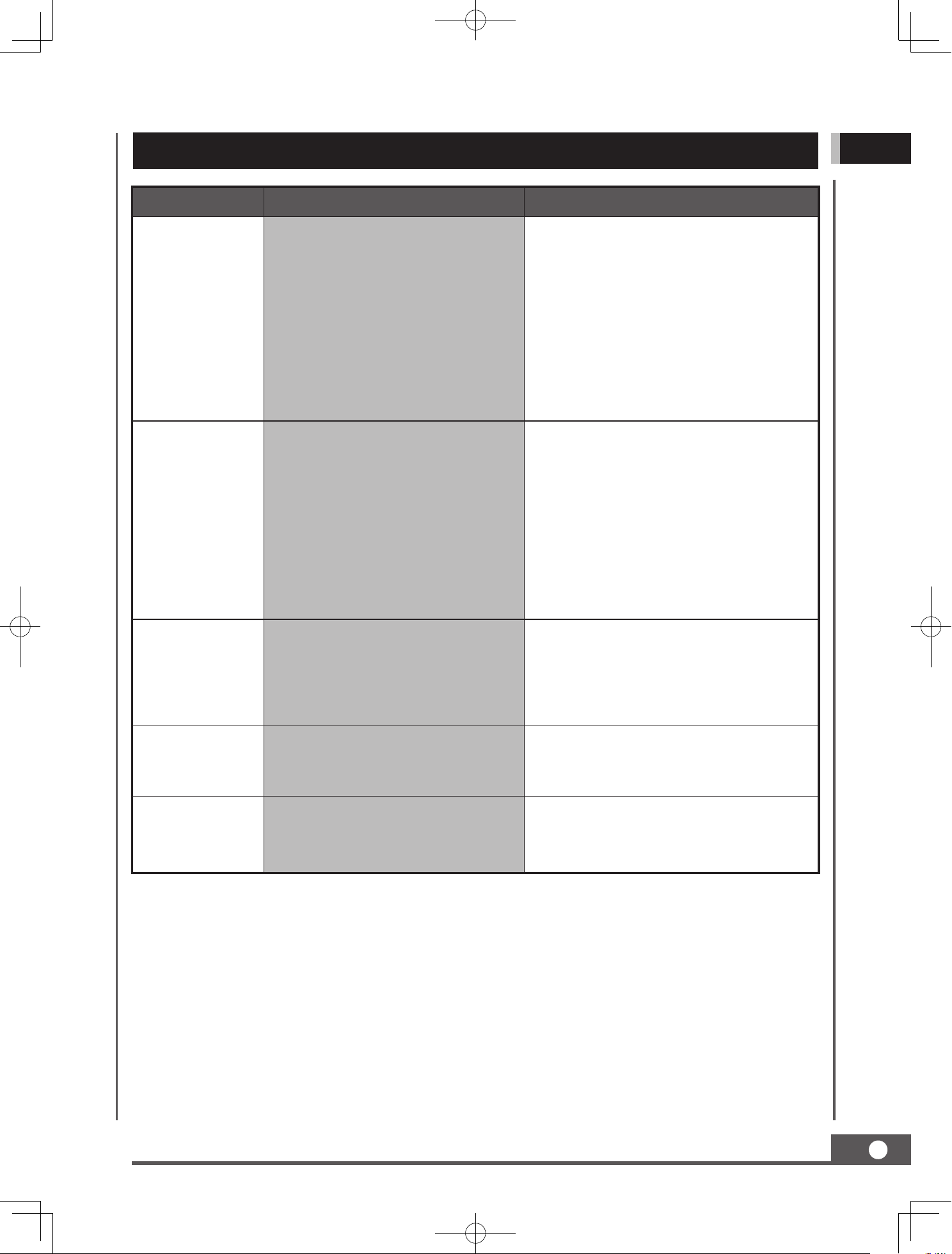
TROUBLE SHOOTING
Problem Cause Remedy
Engine fails to
start.
1. Spark plug wire disconnected.
2. Out of fuel or stale fuel.
3. Choke not in open position.
4. Blocked fuel line.
5. Fouled spark plug.
6. Engine flooding.
1. Attach spark plug wire securely to
spark plug.
2. Fill with clean, fresh gasoline.
3. Throttle must be positioned at choke
for a cold start.
4. Clean the fuel line.
5. Clean, adjust gap, or replace.
6. Wait a few minutes to restart, but do
not prime.
Engine runs
erratically.
1. Spark plug wire loose.
2. Unit running on CHOKE.
3. Blocked fuel line or stale fuel.
4. Vent plugged.
5. Water or dirt in fuel system.
6. Dirty air cleaner.
7. Improper carburetor adjustment.
1. Connect and tighten spark plug wire.
2. Move choke lever to OFF.
3. Clean fuel line. Fill tank with clean,
fresh gasoline.
4. Clear vent.
5. Drain fuel tank. Refill with fresh fuel.
6. Clean or replace air cleaner.
7. Refer to Engine Manual.
Engine
overheats.
1. Engine oil level low.
2. Dirty air cleaner.
3. Air flow restricted.
4. Carburetor not adjusted properly.
1. Fill crankcase with proper oil.
2. Clean air cleaner.
3. Remove housing and clean.
4. Refer to Engine Manual.
One of the two
tracks is blocked.
Foreign bodies have worked their
way between the track and the
frame.
Remove the foreign body.
Machine does
not move while
engine is running.
1. Gear is not properly selected.
2. Driving tracks not tight enough.
1. Ensure gear lever is not in-between
two dierent gears.
2. Tighten driving tracks.
MINI TRACK DUMP CART
20
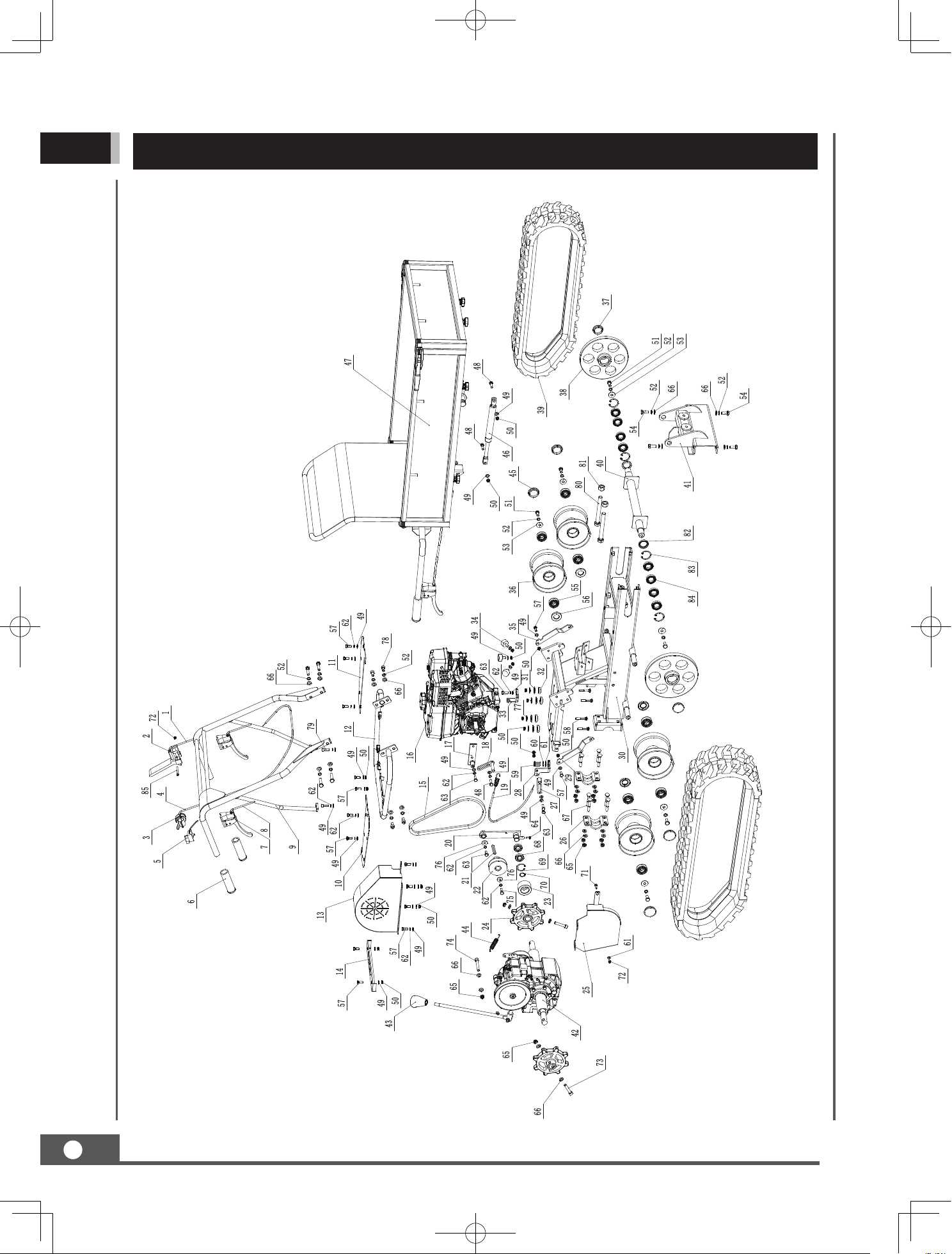
GB
PARTS DIAGRAM
MINI TRACK DUMP CART
21
GB
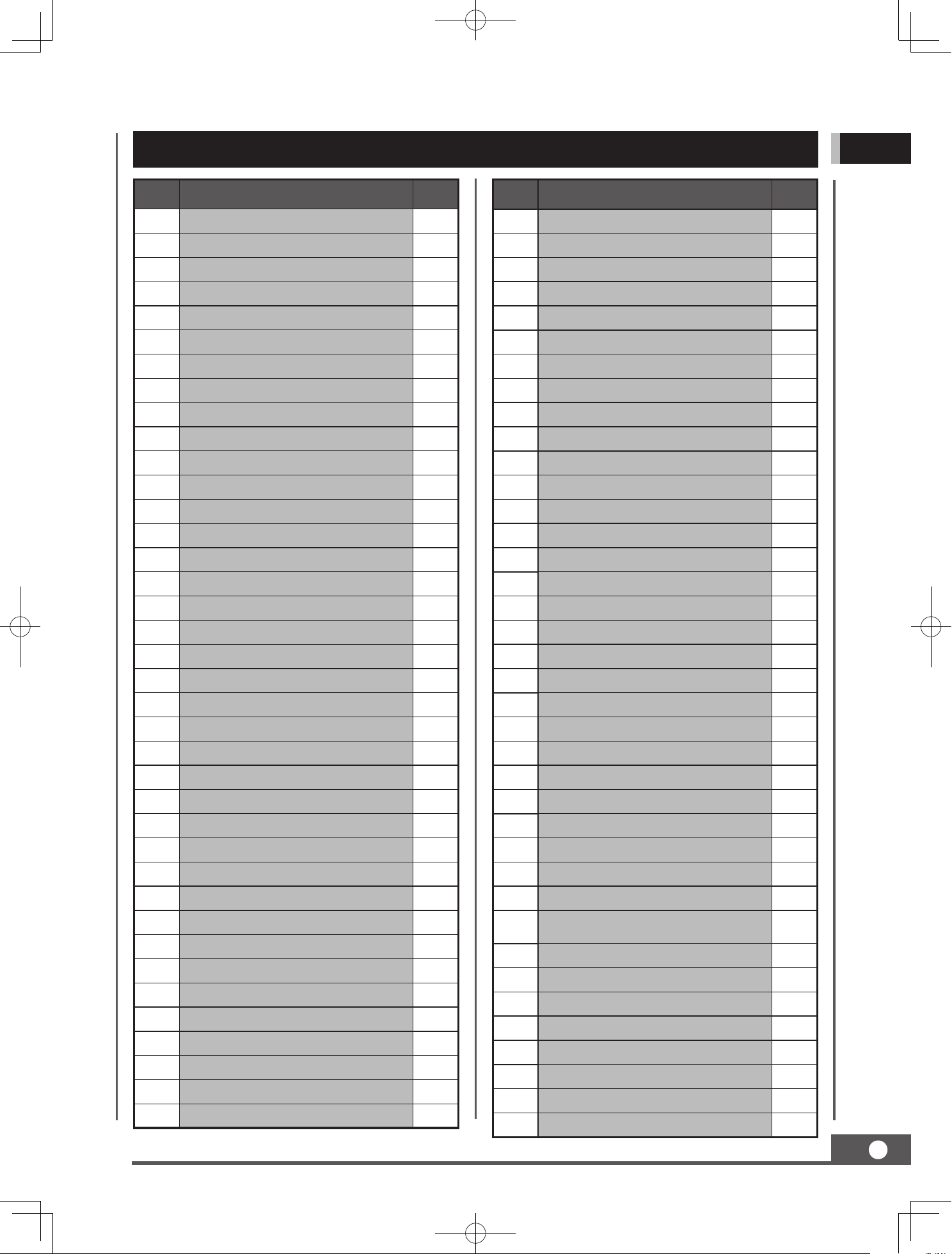
PARTS LIST
No. Description Q'ty
1 Tensioner Pulley Cable 1
2 Safety Control Handle 1
3 Throttle lever 1
4 Throttle cable 1
5 ON/OFF Switch 1
6 Handle Sleeve 3
7 Brake lever 3
8 Stearing lever cable 2
9 Handle frame assembly 1
10 Soleplate (right) 1
11 Soleplate (left) 1
12 Handle mounting frame 1
13 Belt cover 1
14 Gear shift plate 1
15 Belt 1
16 Engine 1
17 Fixed bracket 1
18 Front belt limit board 1
19 Brake cable 1
20 Tensioner pulley bracket 1
21 Engine flat key 1
22 Belt pulley 1
23 Tensioner pulley 1
24 Driving wheel 1
25 Lower belt cover 1
26 Wheel axle mounted plate 2
27 Rear belt limit board 1
28 Connecting angle block 1
29 Support plate (right) 1
30 Chassis 1
31 Gasket 4
32 Rubber shock pad 4
33 Cable fixing base 1
34 Rubber mat 3
35 Support plate (left) 1
36 Track roller 4
37 Dust cap 2
38 Guilding wheel 2
No. Description Q'ty
39 Rubber track 2
40 Guilding wheel axle 1
41 Support bracket 1
42 Gearbox assembly 1
43 Lever knob 1
44 Brake spring 1
45 Dust cap 1
46 Gas spring 1
47 Dumper box assembly 1
48 Hex Bolt M8x30 2
49 Flat washer 8 29
50 Lock nut M8 16
51 Hex Bolt M10x20 6
52 Spring washer 10 18
53 Washer 10 6
54 Hex bolt M10x25 4
55 Bearing 6204 8
56 Oil seal 4
57 Hex bolt M8x20 16
58 Carriage bolt M8x50 4
59 Hex bolt M6x25 2
60 Spring washer 6 2
61 Flat washer 6 3
62 Spring washer 8 17
63 Hex bolt M8x25 4
64 Hex bolt M6x16 1
65 Lock nut M10 12
66 Flat washer 10 27
67 Carriage bolt M10x65 8
68 Bearing 61904 2
69 Circlip 37 1
70 Circlip 20 1
71 Carriage bolt M6x20 1
72 Lock nut M6 2
73 Hex socket bolt M10x55 2
74 Hex socket bolt M10x65 1
75 Bolt 5/16-24x1 1
76 Washer 8 2
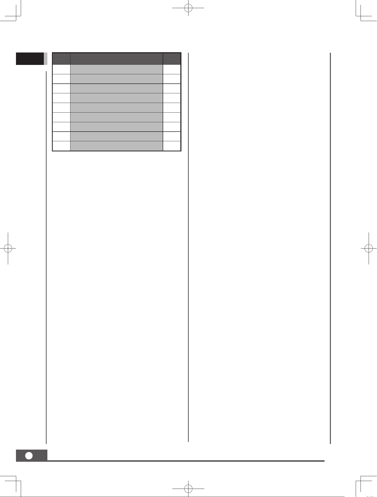
MINI TRACK DUMP CART
22
GB
No. Description Q'ty
77 Washer 8 4
78 Hex socket bolt M10x20 2
79 Hex socket bolt M8x25 2
80 Hex bolt M16x140 2
81 Hex nut M16 2
82 Oil seal 2
83 Circlip 42 4
84 Bearing 61905 8
85 Hex bolt M6x50 1
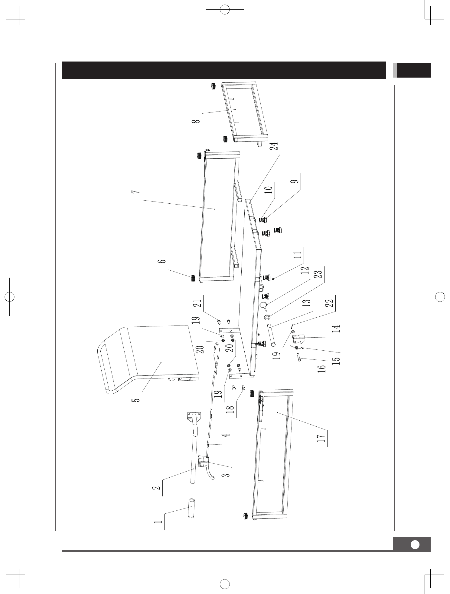
MINI TRACK DUMP CART
PARTS DIAGRAM
23
GB
MINI TRACK DUMP CART
24
GB
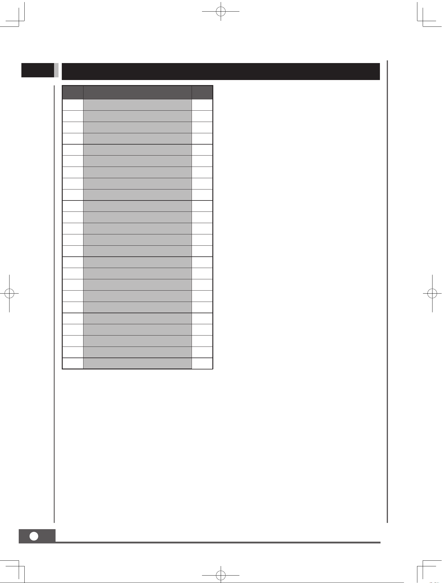
PARTS LIST
No. Description Q'ty
1 Handle sleeve 1
2 Dumper box control lever 1
3 Dumper box handle 1
4 Dumper box control cable 1
5 Back panel 1
6 Plastic plug 6
7 Side panel (left) 1
8 Front panel 1
9 Star bolt M8x16 6
10 Locking spring 6
11 Oil cup M6 1
12 Pin 5x40 1
13 Connecting pin 1
14 Dumper box buckle 1
15 Torsional spring 1
16 Buckle pin 1
17 Side panel (right) 1
18 Hex bolt M10x30 2
19 Flat washer 10 5
20 Lock nut M10 4
21 Hex bolt M10x25 2
22 Split pin 3.2x20 1
23 Flat washer 20 1
24 Bottom panel 1