
1
1. Do not overload the engine crane. This can lead to damage or failure of the
crane. The maximum loading capacity is 2 t.
2. Never use the crane on an uneven surface as this can result in the crane tipping over.
3. Always lock the legs and boom securely in position before lifting a load.
4. All the nuts and screws supplied along with the engine crane are of high strength and
should not be substituted with inferior ones.
5. Before each use, make sure that all nuts and screws are correctly and securely
tightened.
6. Never exceed the safe working loads indicated on the boom of the crane.
7. Do not adjust the relief valve.
8. When moving the crane, always work with a second person. One person should
hold and balance the crane.
9. Do not leave the crane unattended when loaded.
10. Do not make any modifications to the tool.
11. Stop and release compression if you suspect imminent structural failure.
12. Only use identical replacement parts. Use of unauthorized parts or failure to
follow maintenance instructions may create a risk of injury.
Failure to follow these instructions could result in damage to the load being lifted or
the tool, and/or personal injury.
Whilst every effort has been made to ensure the accuracy of the detailed information
provided in this manual, Stark Group LLC., reserves the right to make changes to the technical
information of the product without notice.
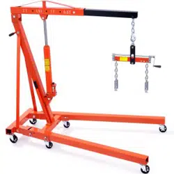
Loading capacity 2 t
4 adjustable positions 1100, 2200, 3300, 4400 lbs
Dimensions (assembly nished) 65 × 39 × 61 in
Dimensions (folded) 21 × 24 × 58 in
Max. lifting height (with min. boom ext.) 69 in
Max. lifting height (with max. boom ext.) 83 in
Length of boom (position 1) 42 in
Length of boom (position 2) 49 in
Length of boom (position 3) 56 in
Length of boom (position 4) 63 in
Net Weight 154 lbs
The above technical information should be taken as a reference only, the detailed information of
the actual product shall prevail.
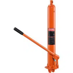
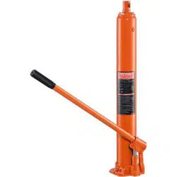
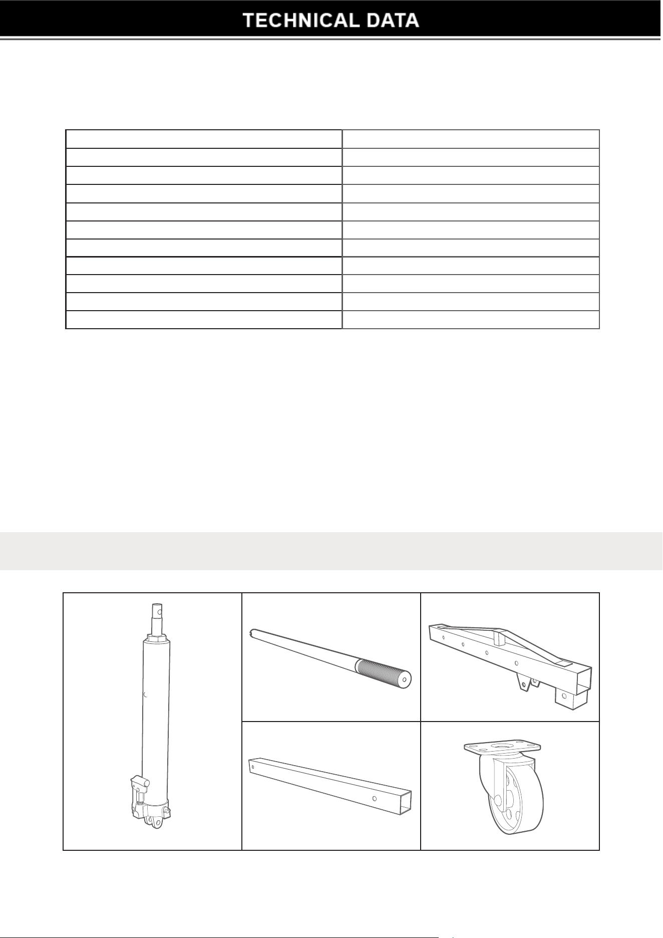
A 1×
Hydraulic cylinder
B 1×
Handle
C 1×
Boom
D 1×
Boom extension
E 2×
3” Swivel caster
parts list
2
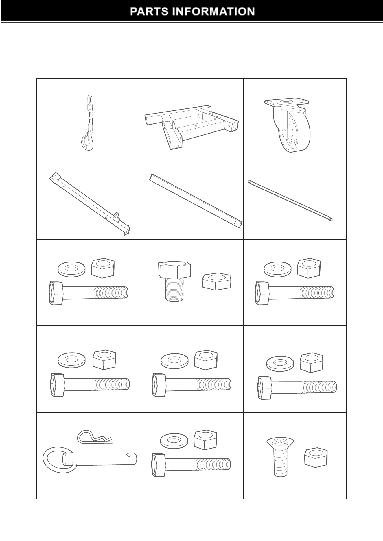
F 1×
Chain and hook
G 1×
Base
H 4×
3.5” Swivel caster
I 1×
Post
J 2×
Leg
K 2×
Support
L 3×
Screw (M16 × 90)
M 16×
Screw (M8 × 12)
N 1×
Screw (M12 × 75)
O 1×
Screw (M14 × 90)
P 2×
Screw (M16 × 75)
Q 1×
Screw (M16 × 120)
R 4×
Locking pin set (Q16 × 100)
S 2×
Screw (M14 × 90)
T 8×
Screw (M8 x 12)
3
C
P
P
D
N
F
O
Q
Q
L
L
I
K
K
A
P
R
L
S
L
L
H
M
R
E
E
T
T
M
E
M
M
M
H
H
H
G
J
J
S
B
T
T
4

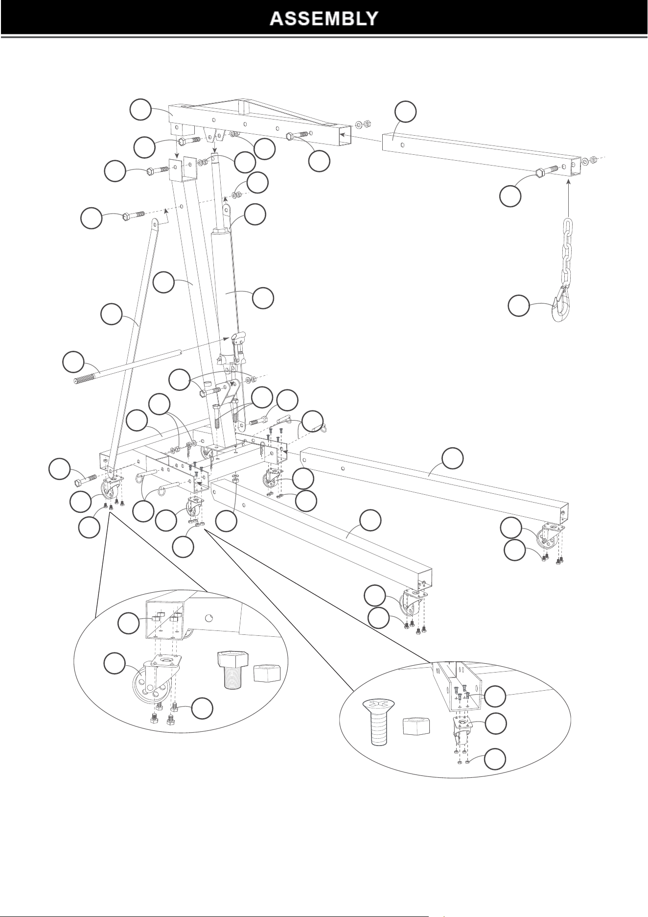
Note: When assembling the item, screw on the nuts and screws on by hand at rst. Once the entire
item has been assembled, fully tighten all the nuts and screws.
1. Attach the two 3” swivel casters (E) to the base (G) using screws and nuts (T). Then attach
two 3.5” swivel casters (H) to the base using nuts and screws (M).
2. Attach one 3.5” swivel caster to the left leg (J) with screws and nuts (M). Then insert the
leg to the base and secure in position with two locking pins (R). Repeat the same operation
for the right leg (J).
3. Attach the post (I) to the base using screws and nuts (S). Then strengthen the post in position
by installing two supports (K) to the base and the post with nuts and screws (L).
4. Now secure the boom (C) to the post using the nut and bolt (Q).
5. Attach the hydraulic cylinder (A) to the post using the nut and bolt (P). Then secure the ram
of the hydraulic cylinder to the boom using the nut and bolt (P).
6. Slide the boom extension (D) into the boom (C) and secure it in one of the four positions of
the boom with the screw (O).
7. Attach the chain and the hook (F) to the boom with the screw (N).
8. Insert the handle (B) into the pump sleeve of the hydraulic cylinder.
9. Fully tighten all nuts and screws.
usaGe
Warning:
• This engine crane is designed for lifting purposes only and not for supporting loads.
• Do not attempt to lift a load which exceeds the rated capacity of the crane.
Important:
It is possible that air can get into the hydraulic system, causing a poor lifting performance of
the crane. With the help of the handle, fully open the release valve of the hydraulic cylinder by
turning counterclockwise to allow excess air to escape from the system. Then insert the handle
into the pump sleeve and operate it rapidly several times while you are holding the boom down.
To raise a load
1. Close the release valve of the hydraulic cylinder by turning clockwise with the slotted end
of the handle. Do not overtighten.
2. Insert the handle into the pump sleeve and pump up and down repeatedly to lift the load
to your desired height.
5
To lower a load
Slowly open the release valve by turning counterclockwise with the slotted end of the handle. The
speed of lowering the load is controlled by how much you turn the handle.

• When adding or replacing oil for the engine crane, always use a high quality hydraulic jack
oil.
• Avoid mixing different types of oil. Do not use brake uid, alcohol, glycerin or dirty oil.
Improper uid can cause serious internal damage to the hydraulic system.
• When adding oil for the hydraulic cylinder, be careful not to allow dirt or foreign objects to
get into the system.
• Check the hydraulic cylinder, especially the ram, every three months for signs of rust or
corrosion. Wipe clean with an oily cloth as needed.
• When not in use, always fully lower the boom to its lowest position.
Storage
When not in use, store the engine crane out of the reach of children.
1. Before storing the engine crane, fully retract the boom extension and lower the boom to its
lowest position.
2. Remove two of the locking pins (R) from the front holes of both legs, leaving the other
two locking pin sets in the rear holes. Then raise up the two legs until they are capable of
leaning against the two supports separately and securely.
3. Place the removed locking pins back to the holes of the base for safe storage.
Note: Failure to follow these instructions may cause the crane to fall over.
5

Problem Possible reason Solution
The crane cannot lift a load.
1. Excess air in the
hydraulic system.
2. Low oil level.
3. The release valve is not
tightened securely.
4. The load exceeds the
rated capacity of the
tool.
1. Deate the excess air in
the hydraulic system.
2. Top up the hydraulic
cylinder as needed.
3. Tighten the release
valve securely.
4. Do not lift the load.
The crane cannot reach its
max. lifting height (or poor
lifting performance).
1. The hydraulic cylinder
has been overlled.
2. Low oil level.
3. Sealing components of
the hydraulic system
has been worn out.
4. Excess air in the
hydraulic system.
1. Check for proper oil
level.
2. Top up the hydraulic
cylinder as needed.
3. Have a qualied
professional replace the
sealing components.
4. Deate the excess air in
the hydraulic system.
The ram of the hydraulic
cylinder cannot lower
completely.
1. Excess air in the
hydraulic system.
2. Lack of lubrication.
1. Deate the excess air in
the hydraulic system.
2. Apply the correct
lubricant to the moving
parts of the tool.
6
7