

Form No. 3473-866 Rev A
e-Dingo
®
500 Compact T ool
Carrier
Model No. 22219 —Serial No. 418037000 and Up
Model No. 22219G —Serial No. 418000000 and Up
Register at www .T oro.com.
Original Instructions (EN)
*3473-866*

This product complies with all relevant European
directives; for details, please see the separate product
specic Declaration of Conformity (DOC) sheet.
This device complies with Part 15 of the FCC Rules.
Operation is subject to the following conditions: (1)
this device may not cause harmful interference, and
(2) this device must accept any interference received,
including interference that may cause undesired
operation. Changes or modications not expressly
approved by T oro could void the user ’ s authority to
operate the equipment.
In addition, while in charging mode this equipment
has been tested and found to comply with the limits
for a Class B digital device, pursuant to Part 15 of
the FCC rules. These limits are designed to provide
reasonable protection against harmful interference in
a residential installation. This equipment generates,
uses and can radiate radio frequency energy and,
if not installed and used in accordance with the
instructions, may cause harmful interference to radio
communications. However , there is no guarantee that
interference will not occur in a particular installation.
If this equipment does cause harmful interference to
radio or television reception, which can be determined
by turning the equipment of f and on, the user is
encouraged to try to correct the interference by one
or more of the following measures:
• Reorient or relocate the receiving antenna.
• Increase the separation between the equipment
and receiver .
• Connect equipment into an outlet on a circuit
dif ferent from that to which the receiver is
connected.
• Consult the dealer or an experienced radio/TV
technician for help.
W ARNING
CALIFORNIA
Proposition 65 W arning
The power cord on this product contains
lead, a chemical known to the State
of California to cause birth defects
or other reproductive harm. W ash
hands after handling.
Battery posts, terminals, and related
accessories contain lead and lead
compounds, chemicals known to
the State of California to cause
cancer and reproductive harm. W ash
hands after handling.
Use of this product may cause exposure
to chemicals known to the State of
California to cause cancer , birth defects,
or other reproductive harm.
Introduction
This machine is a compact tool carrier intended for
use in various earth and materials moving activities for
landscaping and construction work. It is designed to
operate a wide variety of attachments, each of which
perform a specialized function. Using this product
for purposes other than its intended use could prove
dangerous to you and bystanders. Do not modify the
machine or attachments.
This machine should be operated, serviced, and
repaired only by professionals familiar with its
characteristics and acquainted with the relevant safety
procedures.
Operate this machine in ambient temperatures from
-18 to 38°C (0 to 100 °F). Contact your Authorized
Service Dealer for provisions required for operating
in extreme temperatures.
Read this information carefully to learn how to operate
and maintain your product properly and to avoid
injury and product damage. Y ou are responsible for
operating the product properly and safely .
V isit www .T oro.com for product safety and operation
training materials, accessory information, help nding
a dealer , or to register your product.
Whenever you need service, genuine T oro parts, or
additional information, contact an Authorized Service
Dealer or T oro Customer Service and have the model
© 2025—The T oro® Company
81 1 1 L yndale A venue South
Bloomington, MN 55420
2
Contact us at www .T oro.com.
Printed in the USA
All Rights Reserved
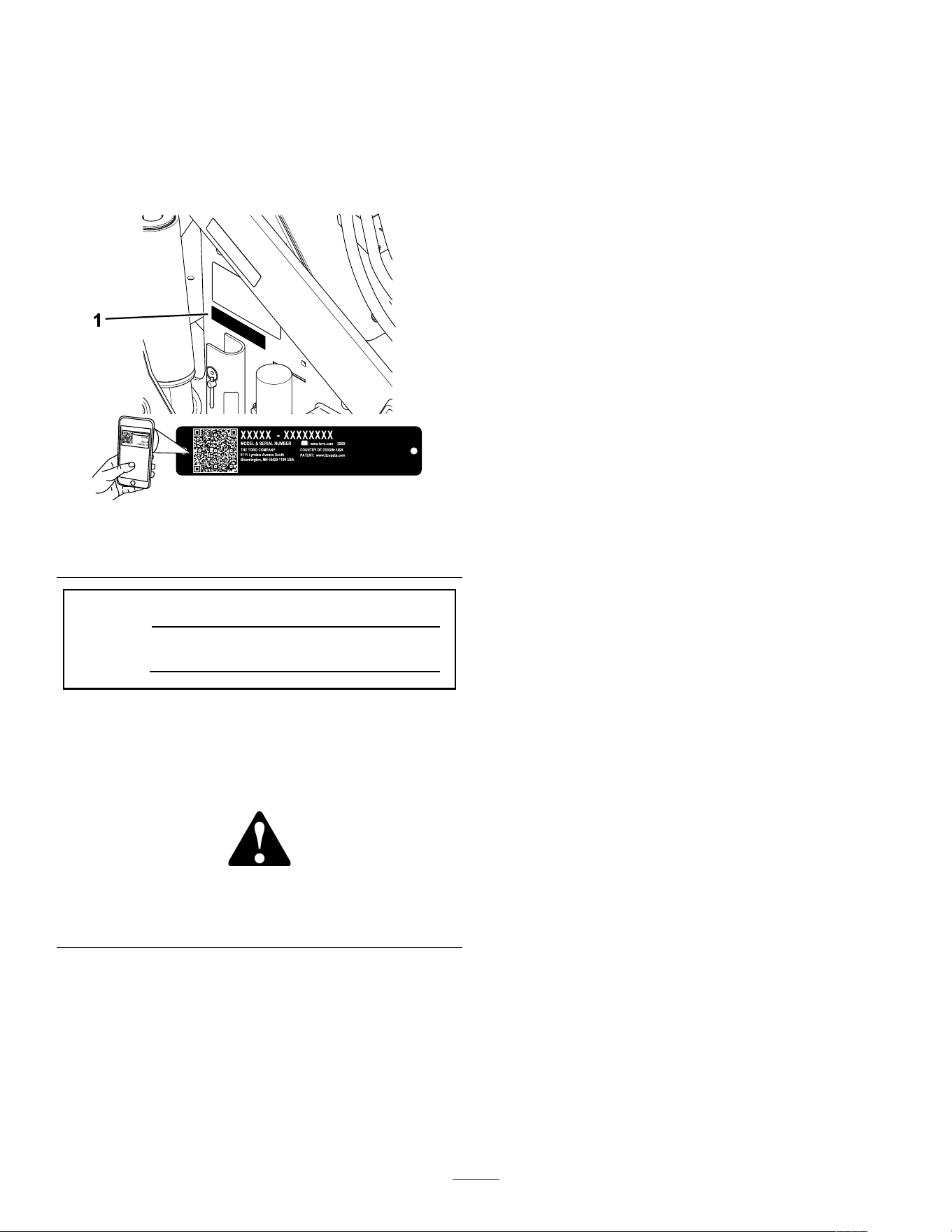
and serial numbers of your product ready . Figure 1
identies the location of the model and serial numbers
on the product. W rite the numbers in the space
provided.
Important: W ith your mobile device, you can
scan the QR code on the serial number decal (if
equipped) to access warranty , parts, and other
product information.
g414804
Figure 1
1. Model and serial number location
Model No.
Serial No.
This manual identies potential hazards and has
safety messages identied by the safety-alert symbol
( Figure 2 ), which signals a hazard that may cause
serious injury or death if you do not follow the
recommended precautions.
g000502
Figure 2
Safety-alert symbol
The safety-alert symbol appears above information
that alerts you to unsafe actions or situations and
is followed by the word DANGER , W ARNING , or
CAUTION .
DANGER indicates an imminently hazardous situation
which, if not avoided, will result in death or serious
injury .
W ARNING indicates a potentially hazardous situation
which, if not avoided, could result in death or serious
injury .
CAUTION indicates a potentially hazardous situation
which, if not avoided, may result in minor or moderate
injury .
This manual uses two other words to highlight
information. Important calls attention to special
mechanical information and Note emphasizes general
information worthy of special attention.
Contents
Safety . . . . . . . . . . . . . . . . . . . . . . . . . . . . . . . . . . . . . . . . . . . . . . . . . . . . . . . . . . . . . . . . . . . . . . . 4
General Safety . . . . . . . . . . . . . . . . . . . . . . . . . . . . . . . . . . . . . . . . . . . . . . . . . . . 4
Safety and Instructional Decals . . . . . . . . . . . . . . . . . . . . . . . . . . 6
Setup . . . . . . . . . . . . . . . . . . . . . . . . . . . . . . . . . . . . . . . . . . . . . . . . . . . . . . . . . . . . . . . . . . . . . . . 1 1
1 Checking the Hydraulic Fluid Level . . . . . . . . . . . . . . . . . 1 1
2 Charging the Batteries . . . . . . . . . . . . . . . . . . . . . . . . . . . . . . . . . . . . 1 1
Product Overview . . . . . . . . . . . . . . . . . . . . . . . . . . . . . . . . . . . . . . . . . . . . . . . . . . . 12
Controls . . . . . . . . . . . . . . . . . . . . . . . . . . . . . . . . . . . . . . . . . . . . . . . . . . . . . . . . . . . 12
InfoCenter Display . . . . . . . . . . . . . . . . . . . . . . . . . . . . . . . . . . . . . . . . 14
Specications . . . . . . . . . . . . . . . . . . . . . . . . . . . . . . . . . . . . . . . . . . . . . . . . . . 16
Attachments/Accessories . . . . . . . . . . . . . . . . . . . . . . . . . . . . . . . . . 16
Before Operation . . . . . . . . . . . . . . . . . . . . . . . . . . . . . . . . . . . . . . . . . . . . . . . . . 17
Before Operation Safety . . . . . . . . . . . . . . . . . . . . . . . . . . . . . . . . . . . 17
Performing Daily Maintenance . . . . . . . . . . . . . . . . . . . . . . . . . . 17
During Operation . . . . . . . . . . . . . . . . . . . . . . . . . . . . . . . . . . . . . . . . . . . . . . . . . 17
During Operation Safety . . . . . . . . . . . . . . . . . . . . . . . . . . . . . . . . . . . 17
Starting the Machine . . . . . . . . . . . . . . . . . . . . . . . . . . . . . . . . . . . . . . . . . 19
Shutting Of f the Machine . . . . . . . . . . . . . . . . . . . . . . . . . . . . . . . . . . 19
Sleep Mode . . . . . . . . . . . . . . . . . . . . . . . . . . . . . . . . . . . . . . . . . . . . . . . . . . . . . . 19
Using Attachments . . . . . . . . . . . . . . . . . . . . . . . . . . . . . . . . . . . . . . . . . . . 19
Changing the Attachment Mode . . . . . . . . . . . . . . . . . . . . . . . . 21
After Operation . . . . . . . . . . . . . . . . . . . . . . . . . . . . . . . . . . . . . . . . . . . . . . . . . . . . 21
After Operation Safety . . . . . . . . . . . . . . . . . . . . . . . . . . . . . . . . . . . . . . 21
Moving a Non-Functioning Machine . . . . . . . . . . . . . . . . . . 22
Lifting the Machine . . . . . . . . . . . . . . . . . . . . . . . . . . . . . . . . . . . . . . . . . . . 23
Hauling the Machine . . . . . . . . . . . . . . . . . . . . . . . . . . . . . . . . . . . . . . . . . 23
T ransporting the Lithium-Ion Batteries . . . . . . . . . . . . . . 25
Charging the Batteries . . . . . . . . . . . . . . . . . . . . . . . . . . . . . . . . . . . . . . 25
Maintenance . . . . . . . . . . . . . . . . . . . . . . . . . . . . . . . . . . . . . . . . . . . . . . . . . . . . . . . . . . . 26
Maintenance Safety . . . . . . . . . . . . . . . . . . . . . . . . . . . . . . . . . . . . . . . . . . 26
Recommended Maintenance Schedule(s) . . . . . . . . . . . 27
Pre-Maintenance Procedures . . . . . . . . . . . . . . . . . . . . . . . . . . . . . . 28
Using the Cylinder Locks . . . . . . . . . . . . . . . . . . . . . . . . . . . . . . . . . . 28
Accessing Internal Components . . . . . . . . . . . . . . . . . . . . . . . 29
Removing the Lower Front Cover . . . . . . . . . . . . . . . . . . . . . 29
Lubrication . . . . . . . . . . . . . . . . . . . . . . . . . . . . . . . . . . . . . . . . . . . . . . . . . . . . . . . . . . 30
Greasing the Machine . . . . . . . . . . . . . . . . . . . . . . . . . . . . . . . . . . . . . . . 30
Electrical System Maintenance . . . . . . . . . . . . . . . . . . . . . . . . . . . 30
Electrical System Safety . . . . . . . . . . . . . . . . . . . . . . . . . . . . . . . . . . . 30
Using the Battery-Disconnect Switch . . . . . . . . . . . . . . . . 30
Replacing the Static Strap . . . . . . . . . . . . . . . . . . . . . . . . . . . . . . . . 31
Servicing the Batteries . . . . . . . . . . . . . . . . . . . . . . . . . . . . . . . . . . . . . . 31
Maintaining the Lithium-Ion Batteries . . . . . . . . . . . . . . . . 31
3

Maintaining the Battery Charger . . . . . . . . . . . . . . . . . . . . . . . 32
Servicing the Fuses . . . . . . . . . . . . . . . . . . . . . . . . . . . . . . . . . . . . . . . . . . 32
Drive System Maintenance . . . . . . . . . . . . . . . . . . . . . . . . . . . . . . . . . . 32
Checking the T ire T reads . . . . . . . . . . . . . . . . . . . . . . . . . . . . . . . . . . 32
Checking the Wheel-Lug Nuts . . . . . . . . . . . . . . . . . . . . . . . . . . 32
Drive-Motor Gear Oil Specications . . . . . . . . . . . . . . . . . . 32
Changing the Drive-Motor Gear Oil . . . . . . . . . . . . . . . . . . . 33
Controls System Maintenance . . . . . . . . . . . . . . . . . . . . . . . . . . . . . 34
Adjusting the Controls . . . . . . . . . . . . . . . . . . . . . . . . . . . . . . . . . . . . . . . 34
Hydraulic System Maintenance . . . . . . . . . . . . . . . . . . . . . . . . . . . 34
Hydraulic System Safety . . . . . . . . . . . . . . . . . . . . . . . . . . . . . . . . . . . 34
Relieving Hydraulic Pressure . . . . . . . . . . . . . . . . . . . . . . . . . . . . 34
Hydraulic Fluid Specications . . . . . . . . . . . . . . . . . . . . . . . . . . . 35
Checking the Hydraulic-Fluid Level . . . . . . . . . . . . . . . . . . . 36
Replacing the Hydraulic Filter . . . . . . . . . . . . . . . . . . . . . . . . . . . 37
Changing the Hydraulic Fluid . . . . . . . . . . . . . . . . . . . . . . . . . . . . 37
Cleaning . . . . . . . . . . . . . . . . . . . . . . . . . . . . . . . . . . . . . . . . . . . . . . . . . . . . . . . . . . . . . . 38
Removing Debris . . . . . . . . . . . . . . . . . . . . . . . . . . . . . . . . . . . . . . . . . . . . . . 38
W ashing the Machine . . . . . . . . . . . . . . . . . . . . . . . . . . . . . . . . . . . . . . . 38
Storage . . . . . . . . . . . . . . . . . . . . . . . . . . . . . . . . . . . . . . . . . . . . . . . . . . . . . . . . . . . . . . . . . . . 39
Storage Safety . . . . . . . . . . . . . . . . . . . . . . . . . . . . . . . . . . . . . . . . . . . . . . . . . . 39
Storing the Machine . . . . . . . . . . . . . . . . . . . . . . . . . . . . . . . . . . . . . . . . . . 39
Battery Storage Requirements . . . . . . . . . . . . . . . . . . . . . . . . . 39
T roubleshooting . . . . . . . . . . . . . . . . . . . . . . . . . . . . . . . . . . . . . . . . . . . . . . . . . . . . . . 40
Safety
General Safety
DANGER
There may be buried utility lines in the work
area. Digging into them may cause a shock
or an explosion.
Have the property or work area marked for
buried lines and do not dig in marked areas.
Contact your local marking service or utility
company to have the property marked (for
example, in the US, call 81 1 or in Australia,
call 1 100 for the nationwide marking service).
Always follow all safety instructions to avoid serious
injury or death. Using this product for purposes other
than its intended use could prove dangerous to you
and bystanders.
• Do not exceed the rated operating capacity , as the
machine may become unstable, which may result
in loss of control.
• Do not carry a load with the arms raised; always
carry loads close to the ground.
• Slopes are a major factor related to loss-of-control
and tip-over accidents, which can result in severe
injury or death. Operating the machine on any
slope or uneven terrain requires extra caution.
• Operate the machine up and down slopes with
the heavy end of the machine uphill and the
load close to the ground. W eight distribution
changes with attachments. An empty bucket
makes the rear of the machine the heavy end, and
a full bucket makes the front of the machine the
heavy end. Most other attachments make the front
of the machine the heavy end.
• Have the property or work area marked for buried
lines and other objects, and do not dig in marked
areas.
• Read and understand the content of this Operator ’ s
Manual before starting the machine.
• Use your full attention while operating the
machine. Do not engage in any activity that
causes distractions; otherwise, injury or property
damage may occur .
• Never allow children or untrained people to
operate the machine.
• Keep your hands and feet away from the moving
components and attachments.
• Do not operate the machine without the guards
and other safety protective devices in place and
working on the machine.
4

• Keep bystanders and children out of the operating
area.
• Stop the machine, shut of f the machine, and
remove the key before servicing or unclogging
the machine.
Improperly using or maintaining this machine can
result in injury . T o reduce the potential for injury ,
comply with these safety instructions and always
pay attention to the safety-alert symbol , which
means Caution, W arning, or Danger—personal safety
instruction. Failure to comply with these instructions
may result in personal injury or death.
5
Safety and Instructional Decals
Safety decals and instructions are easily visible to the operator and are located near any area
of potential danger . Replace any decal that is damaged or missing.
g539127
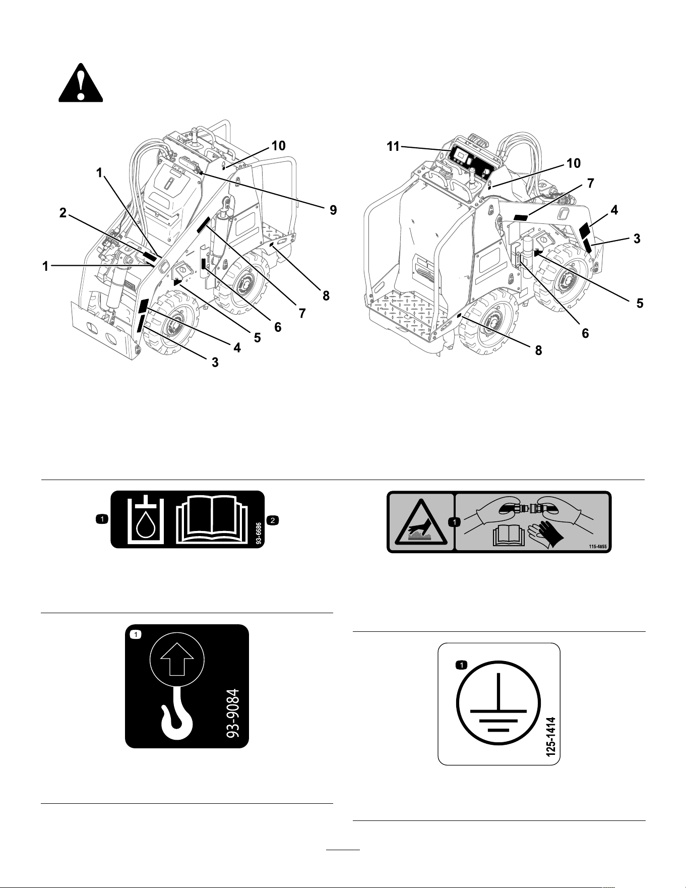
Figure 3
Safety decal locations
1. 130-2837 5. 125-6139 9. 147-0290
2. 1 15-4855 6. 145-4279 10. 93-9084
3. 130-2836 7. 130-2836 1 1. 145-2442
4. 139-7708 8. 132-9051
decal93-6686
93-6686
1. Hydraulic uid 2. Read the Operator's
Manual .
decal93-9084
93-9084
1. Lift point
decal1 15-4855
1 15-4855
1. Hot surface/burn hazard—wear protective gloves when
handling the hydraulic couplers and read the Operator's
Manual for information on handling hydraulic components.
decal125-1414
125-1414
1. Earth (ground) terminal location
6
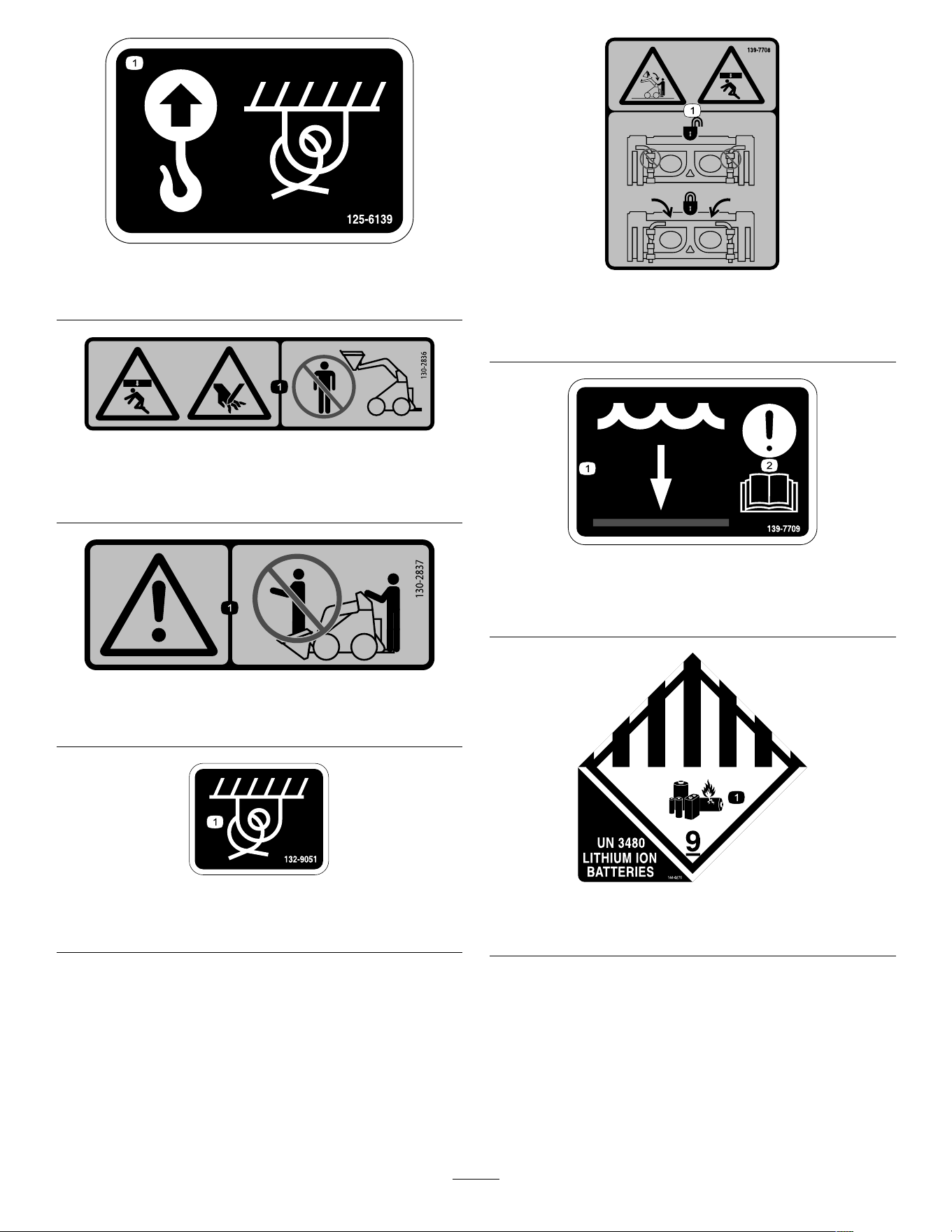
decal125-6139
125-6139
1. Lift point and tie-down point
decal130-2836
130-2836
1. Crushing hazard from above; cutting hazard of the
hand—keep away from the attachment and the lift arm.
decal130-2837
130-2837
1. W arning—do not carry passengers in the bucket.
decal132-9051
132-9051
1. T ie-down point
decal139-7708
139-7708
1. Crushing hazard from above, falling load—ensure that the
quick-attach levers are locked.
decal139-7709
139-7709
1. W ater level 2. Attention—read the
Operator ’ s Manual .
decal144-0275
144-0275
1. Batteries are ammable.
7
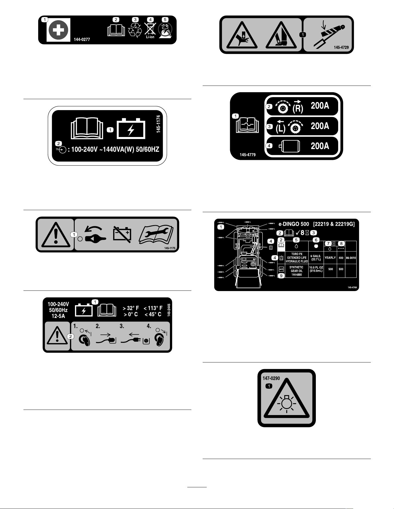
decal144-0277
144-0277
1. Positive terminal 4. Do not dispose improperly .
2. Read the Operator ’ s
Manual .
5. Do not expose to re.
3. Recycle the battery .
decal145-1 174
145-1 174
1. Read the Operator ’ s
Manual for battery
charging information.
2. Battery charger input
specications.
decal145-1 175
145-1 175
1. W arning—turn the battery disconnect switch to the O FF
position before performing maintenance.
decal145-2445
145-2445
1. Keep the battery at
a temperature above
0°C (32°F) and below
45°C (1 13°F); read the
Operator ’ s Manual .
2. W arning—turn the
machine of f before
plugging it in; unplug the
machine before turning it
on.
decal145-4729
145-4729
1. Crushing hazard of hands or feet—install the cylinder lock.
decal145-4779
145-4779
1. Read the Operator's
Manual for fuse
information.
3. Left traction
2. Right traction 4. Hydraulic motor
decal145-4789
145-4789
1. Grease points 6. Capacity
2. Read the Operator ’ s
Manual.
7. Fluid interval (hours)
3. Check every 8 hours. 8. Filter interval (hours)
4. Hydraulic uid 9. Gearbox
5. Fluids
decal147-0290
147-0290
1. W arning—light is bright; do not look directly into the light.
8
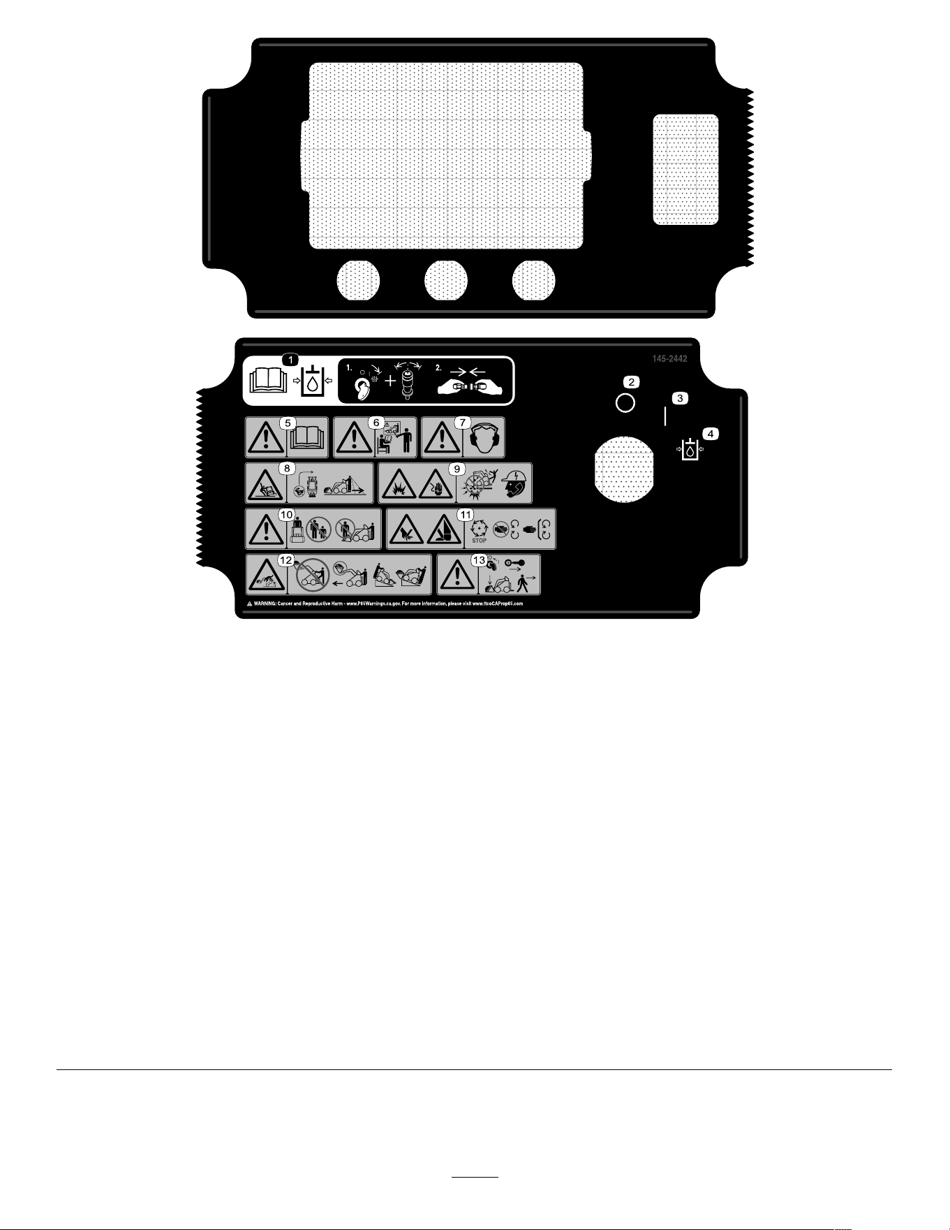
decal145-2442
145-2442
1. Read the Operator ’ s Manual before connecting or
disconnecting the auxiliary hydraulic couplers—1) T urn and
hold the key in the auxiliary hydraulic relief position and press
the auxiliary-hydraulic control switch back and forth to relieve
hydraulic pressure; 2) Connect or disconnect the auxiliary
hydraulic couplers.
8. T ipping hazard—do not make fast turns; always check behind
you before reversing the machine.
2. Of f
9. Explosion hazard; electrocution hazard—call the local utilities
hotline before beginning work in an area.
3. On 10. W arning—keep away from the attachment when operating the
machine; keep bystanders away from the machine.
4. Auxiliary hydraulic relief position 1 1. Cutting/severing hazard of hand or foot—wait for all moving
parts to stop before servicing; keep away from moving parts;
keep all guards and shields in place.
5. W arning—read the Operator's Manual . 12. T ipping hazard—do not step of f the operator platform with the
load raised; do not drive the machine with the load raised;
always move up or down slopes with the attachment lowered;
never drive on a slope with the attachment raised; always
operate with the heavy end uphill; always carry loads low;
never jerk the control levers; use a steady , even motion.
6. W arning—receive training before operating the machine.
13. W arning—engage the parking brake, lower the attachment to
the ground, shut of f the machine, and remove the key from
the key switch before leaving the machine.
7. W arning—wear hearing protection.
9
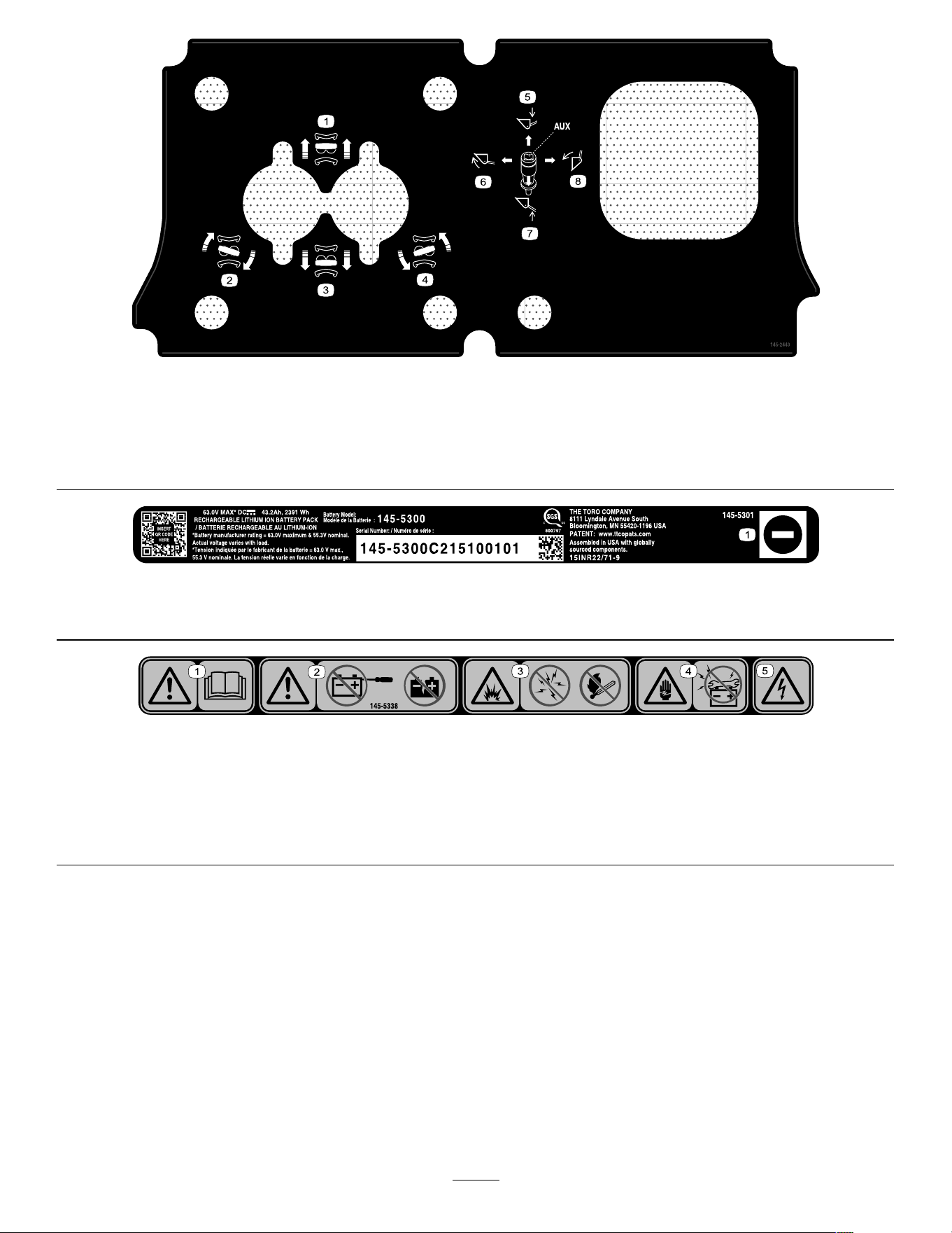
decal145-2443
145-2443
1. Move forward
5. Lower the attachment
2. T urn right 6. T ilt the attachment rearward
3. Move rearward 7. Raise the attachment
4. T urn left 8. T ilt the attachment forward
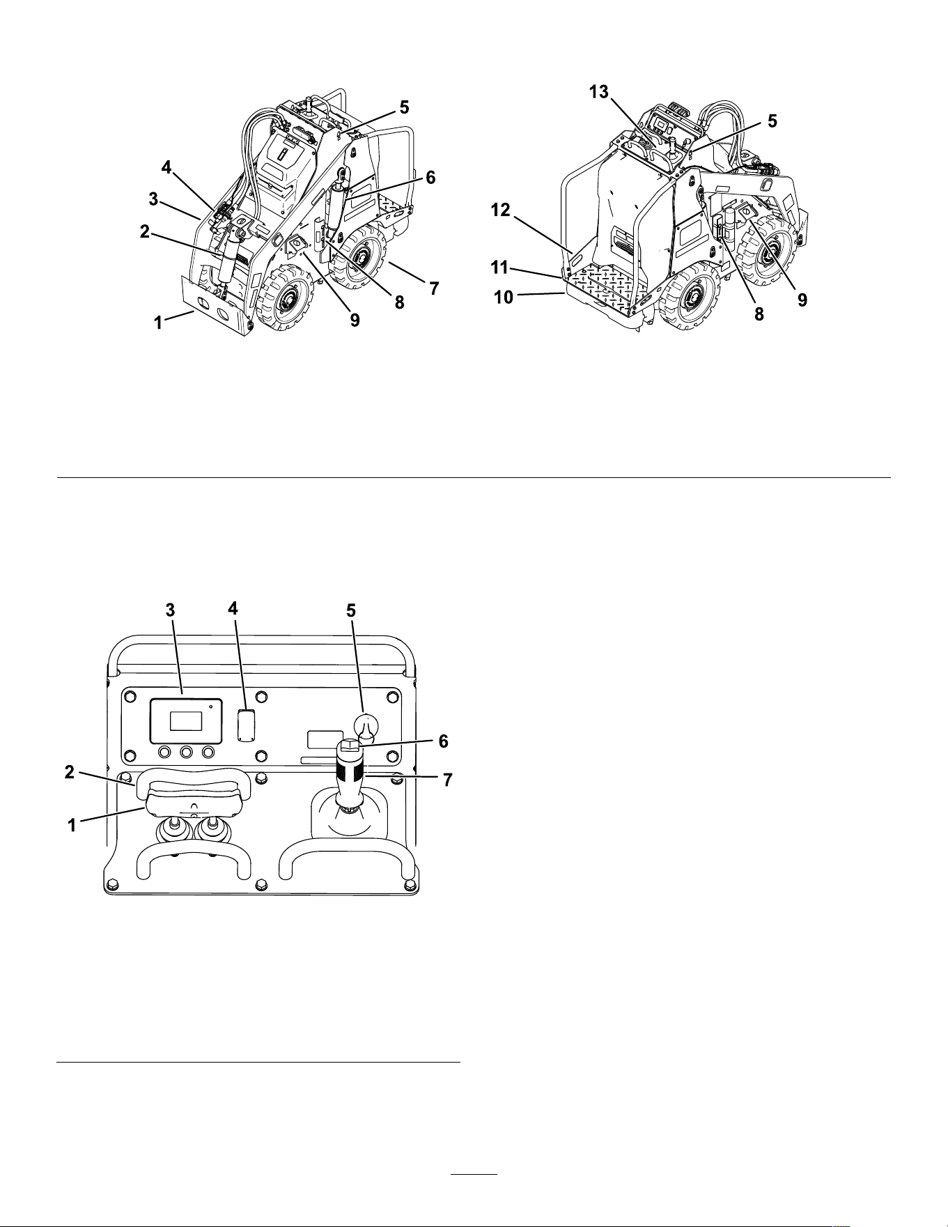
decal145-5301
145-5301
1. Negative battery terminal
decal145-5338
145-5338
1. W arning—read the Operator ’ s Manual . 4. Electric shock hazard—do not perform maintenance on the
battery .
2. W arning—do not open the battery; do not use a damaged
battery .
5. Electric shock hazard
3. Explosion hazard—do not expose to sparks or open ame.
10

Setup
1
Checking the Hydraulic
Fluid Level
No Parts Required
Procedure
Before starting the machine for the rst time, check
the hydraulic-uid level; refer to Checking the
Hydraulic-Fluid Level ( page 36 ) .
2
Charging the Batteries
No Parts Required
Procedure
Charge the batteries; refer to Charging the Batteries
( page 25 ) .
1 1
Product Overview
g340975
Figure 4
1. Attachment mount plate
5. Lift point 9. T ie-down/lift point 13. Control panel
2. T ilt cylinder
6. Lift cylinder 10. Counterweight
3. Loader arm 7. Wheel
1 1. Operator platform
4. Auxiliary hydraulic couplers
8. Cylinder locks
12. T ie-down point
Controls
Control Panel
g340974
Figure 5
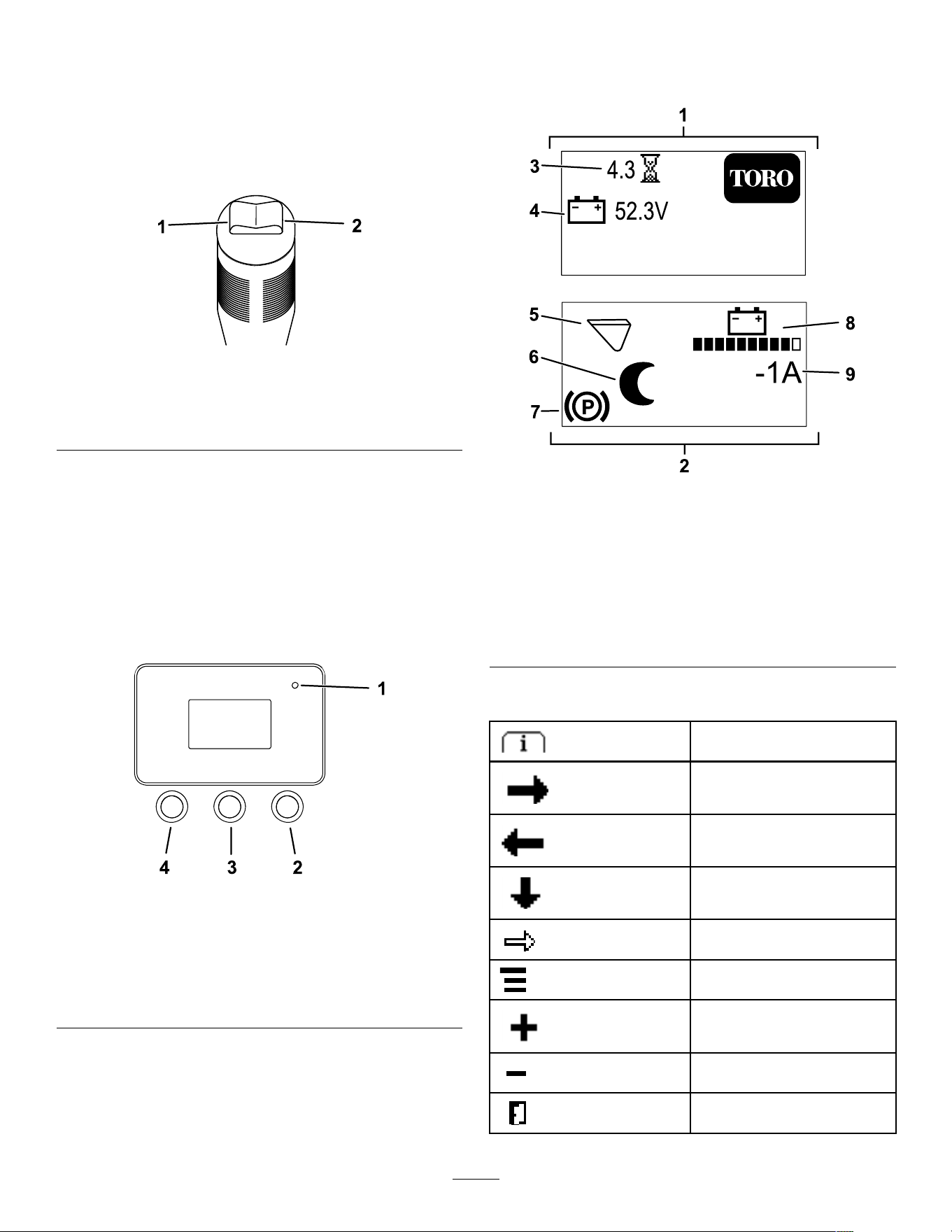
1. T raction control 5. Key switch
2. Reference bar
6. Auxiliary-hydraulics
control
3. InfoCenter 7. Loader-arm/attachment tilt
lever
4. Light switch
Key Switch
The key switch has 3 positions: O N , O FF , and
A UXILIARY HYDRAULIC RELIEF .
Use the key switch to start, shut of f, and relieve
auxiliary hydraulic pressure on the machine.
Parking Brake
The parking brake engages automatically when you
stop the machine and release the traction control to
neutral. An icon appears on the InfoCenter display
when the parking brake is engaged.
The parking brake disengages when you move the
traction control.
Reference Bar
When driving the traction unit, use the reference bar
as a handle and a leverage point for controlling the
traction control and the auxiliary-hydraulics lever . T o
ensure smooth, controlled operation, do not take
your hands of f the reference bars while operating the
machine.
12
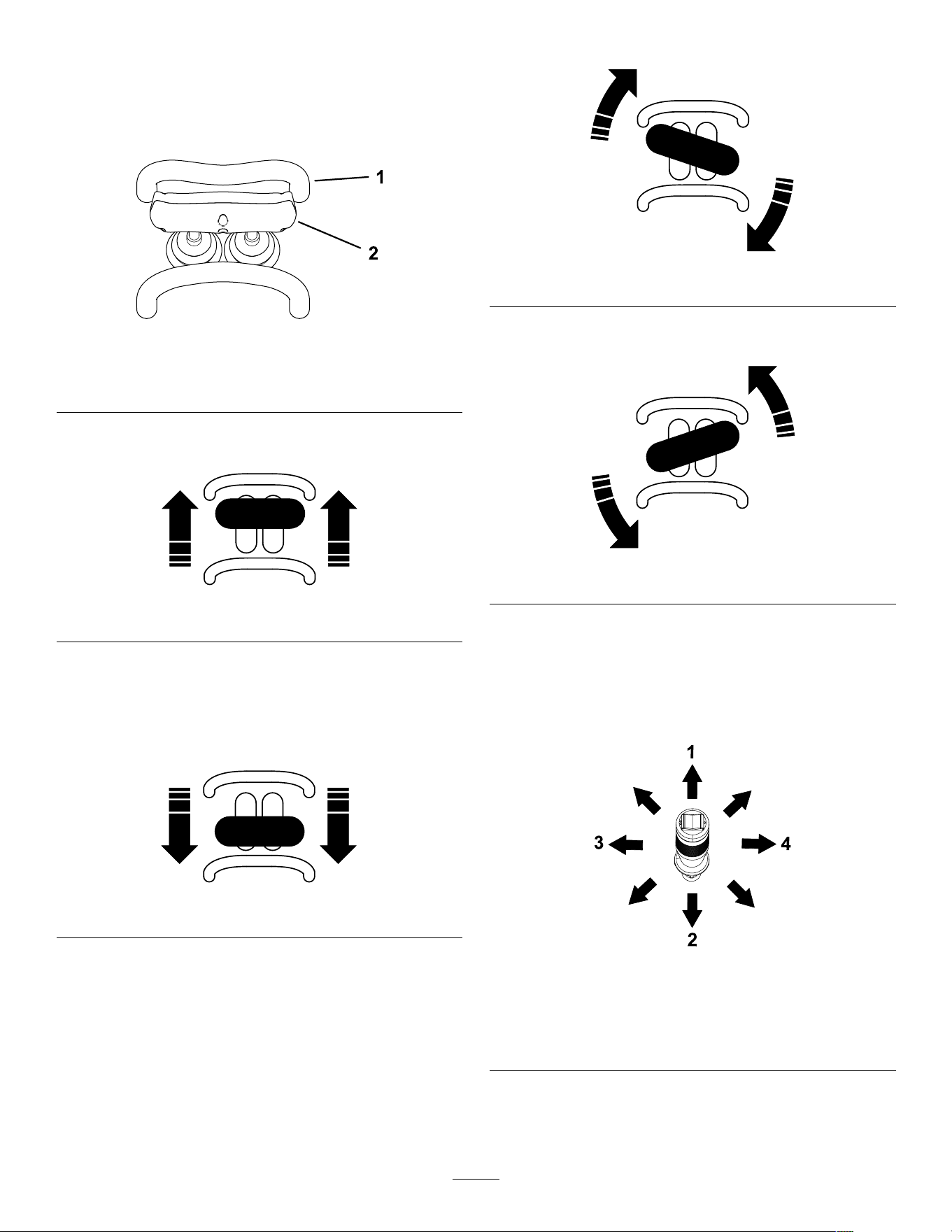
T raction Control
Use the traction control to move the machine. The
farther you move the traction control in any direction,
the faster the machine moves in that direction.
Release the traction control to stop the machine.
g264835
Figure 6
1. Reference bar
2. T raction control
• T o move forward, move the traction control
forward.
g264830
Figure 7
• T o move rearward, move the traction control
rearward.
Important: When reversing, look behind you
for obstructions and keep your hands on the
reference bar .
g264831
Figure 8
• T o turn right, rotate the traction control clockwise.
g264833
Figure 9
• T o turn left, rotate the traction control
counterclockwise.
g264832
Figure 10
• T o stop the machine, release the traction control.
Loader Arm/Attachment-T ilt Lever
Slowly move the lever to operate the loader arms and
tilt the attachment.
g386336
Figure 1 1
1. Lower the loader arms. 3. T ilt the attachment
rearward.
2. Raise the loader arms. 4. T ilt the attachment
forward.
By moving the lever to an intermediate position (e.g.,
forward and left), you can move the loader arms and
tilt the attachment at the same time.
13
Loader-Control-Reference Bar
The loader-control-reference bar helps stabilize your
hand while operating the loader arm/attachment-tilt
lever ( Figure 5 ).
Auxiliary-Hydraulics Controls
g386338
Figure 12
1. Operate auxiliary
hydraulics in the forward
direction.
2. Operate auxiliary
hydraulics in the reverse
direction.
InfoCenter Display
The InfoCenter LCD display shows information about
your machine, such as the operating status and
various diagnostics. There is a splash screen and
main information screen of the InfoCenter . T o switch
between the splash screen and main information
screen at any time, press any InfoCenter button and
then press the right button.
g264015
Figure 13
1. Indicator light 3. Middle button—scroll
down menus
2. Right button—open a
menu where a right
arrow indicates additional
content
4. Left button—access
menus and exit any menu
Note: The purpose of each button may change
depending on what is required at the time. Each
button is labeled with an icon displaying its current
function.
The splash screen displays for a few seconds after
you turn the key to the O N position and then the run
screen displays.
g390675
Figure 14
1. Splash screen 6. Sleep mode is active.
2. Run screen 7. Parking brake is engaged.
3. Hours operated 8. Battery charge
4. Battery voltage 9. Instantaneous machine
amperage
5. Attachment mode (Bucket
Mode shown)
InfoCenter Icon Descriptions
Menu access
Next
Previous
Scroll down
Enter
Change the current selection.
Increase
Decrease
Exit menu
14
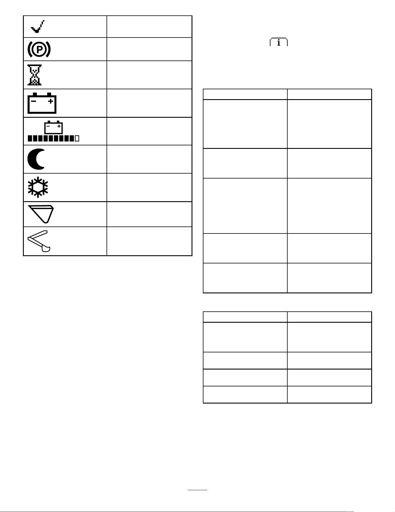
Check PIN entry
Parking brake is engaged.
Hour meter
Battery voltage
Battery charge—each solid bar
represents the charge in 10%
increments.
Sleep Mode is active.
Cold Start Mode is active.
Bucket Mode is active.
Backhoe Mode is active.
InfoCenter Menus
T o access the InfoCenter menu system, press the
menu access button while at the main screen.
This will bring you to the main menu. Refer to the
following tables for a synopsis of the options available
from the menus:
Main Menu
Menu Item Description
F AULTS
The F AULTS menu contains
a list of the recent machine
faults. Refer to the Service
Manual or your Authorized
Service Dealer for more
information on the F AULTS
menu.
S ERVICE
The S ERVICE menu contains
information on the machine
such as hours of use and other
similar numbers.
D IAGNOSTICS
The D IAGNOSTICS menu
displays the state of each
machine switch, sensor , and
control output. Use this
information to troubleshoot
certain issues, as it quickly
tells you which machine
controls are on or of f.
S ETTINGS The S ETTINGS menu allows
you to customize and modify
conguration variables on the
InfoCenter display .
A BOUT The A BOUT menu lists the
model number , serial number ,
and software version of your
machine.
Faults
Menu Item Description
C URRENT Lists the total number of
key-on hours (i.e., hours that
the key has been in the O N
position).
L AST Indicates the last key-on hour
that the fault occurred on.
F IRST
Indicates the rst key-on hour
that the fault occurred on.
O CCURRENCES Indicates the number of fault
occurrences.
15

Service
Menu Item Description
H OURS
Lists the total number of
hours that the key , motors,
and attachment modes have
been on and the hours
that the traction controls
and hydraulics have been
engaged.
C OUNTS Lists the number of hydraulic
motor starts, charge cycles,
and low battery alerts.
T RACTION CALIBRATION
Calibrates the traction control.
Diagnostics
Menu Item Description
B ATTERY Indicates the inputs and
outputs for the battery . Inputs
include the current battery
voltage; outputs include the
battery current and percentage
state of charge.
CAN
Indicates the status, health,
and utilization of the CAN bus.
M OTOR CONTROL Indicates the inputs and
outputs for the motor control.
Inputs include key run, key
start, parking brake, auxiliary ,
raise/lower , bucket curl,
backhoe seat, logic voltage,
motor voltage, DC current;
use these to check input
feedback on the machine.
Outputs include motor speed
(in rpm), phase current, motor
torque, controller temperature,
motor temperature,
electromechanical brake,
contactor , auxiliary , 5 and 12
V supply , and drivers.
Settings
Menu Item Description
L ANGUAGE
Controls the language used
on the InfoCenter .
B ACKLIGHT
Controls the brightness of the
LCD display
C ONTRAST Controls the contrast of the
LCD display .
P ROTECTED M ENUS Allows you to access
protected menus by inputting
a passcode.
About
Menu Item Description
M ODEL
Lists the model number of the
machine
S ERIAL Lists the serial number of the
machine
S/W R EV Lists the software revision of
the master controller .
M OTOR C TRL SW Lists the software revision of
the motor control.
B ATTERY SW Lists the software revision of
the battery .
Specications
Note: Specications and design are subject to
change without notice.
Width
76 cm (30 inches)
Length
168 cm (66 inches)
Height
138 cm (54 inches)
W eight (without attachment) 1062 kg (2342 lb)
Rated operating capacity—with 74.8
kg (165 lb) operator and the standard
bucket
234 kg (515 lb)
T ipping capacity—with 74.8 kg (165 lb)
operator and the standard bucket
567 kg (1251 lb)
Wheelbase
71 cm (28 inches)
Dump height (with standard bucket) 160 cm (63 inches)
Reach—fully raised (with standard
bucket)
55 cm (22-1/2
inches)
Height to hinge pin (narrow bucket in
standard position)
206 cm (81 inches)
A verage ground pressure (with empty
standard bucket)
579 kPa (84 psi)
A verage ground pressure (at rated
operating capacity)
620 kPa (90 psi)
Attachments/Accessories
A selection of T oro approved attachments and
accessories is available for use with the machine
to enhance and expand its capabilities. Contact
your Authorized Service Dealer or authorized T oro
distributor or go to www .T oro.com for a list of all
approved attachments and accessories.
T o ensure optimum performance and continued safety
certication of the machine, use only genuine T oro
replacement parts and accessories. Replacement
parts and accessories made by other manufacturers
could be dangerous, and such use could void the
product warranty .
16

Operation
Before Operation
Before Operation Safety
General Safety
• Never allow children or untrained people to
operate or service the machine. Local regulations
may restrict the age or require certied training of
the operator . The owner is responsible for training
all operators and mechanics.
• Become familiar with the safe operation of the
equipment, operator controls, and safety decals.
• Always engage the parking brake, shut of f the
machine, remove the key , wait for all moving
parts to stop, and allow the machine to cool
before adjusting, servicing, cleaning, or storing
the machine.
• Know how to stop the machine and shut of f the
machine quickly .
• Check that the safety switches and shields are
attached and functioning properly . Do not operate
the machine unless they are functioning properly .
• Locate the pinch-point areas marked on the
machine and attachments; keep your hands and
feet away from these areas.
• Before operating the machine with an attachment,
ensure that the attachment is properly installed
and that it is a genuine T oro attachment. Read all
the attachment manuals.
• Evaluate the terrain to determine what accessories
and attachments you need to properly and safely
perform the job.
• Have the property or work area marked for buried
lines and other objects, and do not dig in marked
areas; note the location of unmarked objects and
structures, such as underground storage tanks,
wells, and septic systems.
• Inspect the area where you will use the equipment
for uneven surfaces or hidden hazards.
• Ensure that the area is clear of bystanders before
operating the machine. Stop the machine if a
bystander enters the area.
Performing Daily
Maintenance
Before starting the machine each day , perform the
Each Use/Daily procedures listed in Maintenance
( page 26 ) .
During Operation
During Operation Safety
General Safety
• Do not exceed the rated operating capacity , as the
machine may become unstable, which may result
in loss of control.
• Do not carry a load with the arms raised. Always
carry loads close to the ground.
• Use only T oro-approved attachments and
accessories. Attachments can change the stability
and the operating characteristics of the machine.
• For machines with a platform:
– Lower the loader arms before stepping of f the
platform.
– Do not try to stabilize the machine by putting
your foot on the ground. If you lose control of
the machine, step of f the platform and away
from the machine.
– Do not place your feet under the platform.
– Do not move the machine unless you are
standing with both feet on the platform and your
hands are holding onto the reference bars.
• Use your full attention while operating the
machine. Do not engage in any activity that
causes distractions; otherwise, injury or property
damage may occur .
• Look behind and down before backing up to
ensure that the path is clear .
• Never jerk the controls; use a steady motion.
• The owner/user can prevent and is responsible
for accidents that may cause personal injury or
property damage.
• W ear appropriate clothing including gloves, eye
protection, long pants, substantial slip-resistant
footwear , and hearing protection. T ie back long
hair and do not wear loose clothing or loose
jewelry .
• Do not operate the machine when you are tired, ill,
or under the inuence of alcohol or drugs.
• Never carry passengers and keep pets and
bystanders away from the machine.
• Operate the machine only in good light, keeping
away from holes and hidden hazards.
• Ensure that all the drives are in neutral before
starting the machine. Start the machine only from
the operator's position.
• Use care when approaching blind corners, shrubs,
trees, or other objects that may obscure vision.
17

• Slow down and use caution when making turns
and crossing roads and sidewalks. W atch for
traf c.
• Stop the attachment when you are not working.
• Stop the machine, shut of f the machine, remove
the key , and inspect the machine if you strike
an object. Make any necessary repairs before
resuming operation.
• Never leave a machine on when unattended.
• Before leaving the operating position, do the
following:
– Park the machine on a level surface.
– Lower the loader arms and disengage the
auxiliary hydraulics.
– Shut of f the machine and remove the key .
• Do not operate the machine when there is the risk
of lightning.
• Operate the machine only in areas where there is
suf cient clearance for you to safely maneuver .
Be aware of obstacles in close proximity to you.
Failure to maintain adequate distance from trees,
walls, and other barriers may result in injury as the
machine backs up during operation if you are not
attentive to the surroundings.
• Check for overhead clearance (i.e., electrical
wires, branches, ceilings, and doorways) before
driving under any objects and do not contact them.
• Do not overll the attachment and always keep the
load level when raising the loader arms. Items in
the attachment could fall and cause injury .
Slope Safety
• Operate the machine up and down slopes with
the heavy end of the machine uphill. W eight
distribution changes with attachments. An empty
bucket makes the rear of the machine the heavy
end, and a full bucket makes the front of the
machine the heavy end. Most other attachments
make the front of machine the heavy end.
• Raising the loader arms on a slope af fects the
stability of the machine. Keep the loader arms in
the lowered position when on slopes.
• Slopes are a major factor related to loss of control
and tip-over accidents, which can result in severe
injury or death. Operating the machine on any
slope or uneven terrain requires extra caution.
• Establish your own procedures and rules for
operating on slopes. These procedures must
include surveying the site to determine which
slopes are safe for machine operation. Always
use common sense and good judgment when
performing this survey .
• Slow down and use extra care on hillsides. Ground
conditions can af fect the stability of the machine.
• A void starting or stopping on a slope. If the
machine loses traction, proceed slowly , straight
down the slope.
• A void turning on slopes. If you must turn, turn
slowly and keep the heavy end of the machine
uphill.
• Keep all movements on slopes slow and gradual.
Do not make sudden changes in speed or
direction.
• If you feel uneasy operating the machine on a
slope, do not do it.
• W atch for holes, ruts, or bumps, as uneven terrain
could overturn the machine. T all grass can hide
obstacles.
• Use caution when operating on wet surfaces.
Reduced traction could cause sliding.
• Evaluate the area to ensure that the ground is
stable enough to support the machine.
• Use caution when operating the machine near the
following:
– Drop-of fs
– Ditches
– Embankments
– Bodies of water
The machine could suddenly roll over if a track
goes over the edge or the edge caves in. Maintain
a safe distance between the machine and any
hazard.
• Do not remove or add attachments on a slope.
• Do not park the machine on a hillside or slope.
Utility Line Safety
• If you strike a utility line, do the following:
– Shut of f the machine and remove the key .
– Remove all individuals from the work area.
– Immediately contact the proper emergency and
utility authorities to secure the area.
– If you damage a ber-optic cable, do not look
into the exposed light.
• Do not leave the operator ’ s platform if the machine
is charged with electricity . Y ou will be safe as long
as you do not leave the platform.
– T ouching any part of the machine may ground
you.
– Do not allow another individual to touch or
approach the machine when charged.
– Always assume the machine is charged if you
strike an electrical or communication line. Do
not attempt to leave the machine.
• Leaking gas is both ammable and explosive and
may cause serious injury or death. Do not smoke
while operating the machine.
18
Starting the Machine
1. Ensure that the battery-pack is connected to
the machine.
2. Ensure that the battery-disconnect switch is in
the ON position.
3. Stand on the platform.
4. Ensure that the loader-arm/attachment-tilt lever
and traction control are in the N EUTRAL position.
5. Insert the key into the key switch and turn it to
the O N position.
Note: The machine may have dif culty starting under
severe cold conditions. When starting a cold machine,
keep the machine above -18°C (0°F).
Note: When the machine temperature is below
-1°C (30°F), the cold-start symbol will appear on the
InfoCenter while the hydraulic uid warms. Hydraulic
function may be reduced during this time. The
cold-start symbol disappears when the uid is warm.
g304012
Figure 15
Shutting Off the Machine
1. Park the machine on a level surface and lower
the loader arms.
2. Disengage the auxiliary hydraulics.
3. Ensure that the loader-arm/attachment-tilt lever
and traction control are in the N EUTRAL position.
4. T urn the key switch to the O FF position and
remove the key .
Note: The parking brake engages automatically
when you stop the machine and release the traction
control to the N EUTRAL position.
CAUTION
Children or bystanders may be injured if they
move or attempt to operate the machine while
it is unattended.
Always remove the key when leaving the
machine unattended.
Sleep Mode
After 30 seconds of inactivity , the machine goes into
sleep mode and displays the sleep mode icon on
the InfoCenter . Hydraulics and traction controls are
disabled during sleep mode.
T o resume normal operation, rapidly move the traction
control twice.
After 5 minutes, the machine shuts of f; cycle the key
to start the machine again.
Using Attachments
Installing an Attachment
Important: Use only T oro-approved attachments.
Attachments can change the stability and the
operating characteristics of the machine. The
warranty of the machine may be voided if you use
the machine with unapproved attachments.
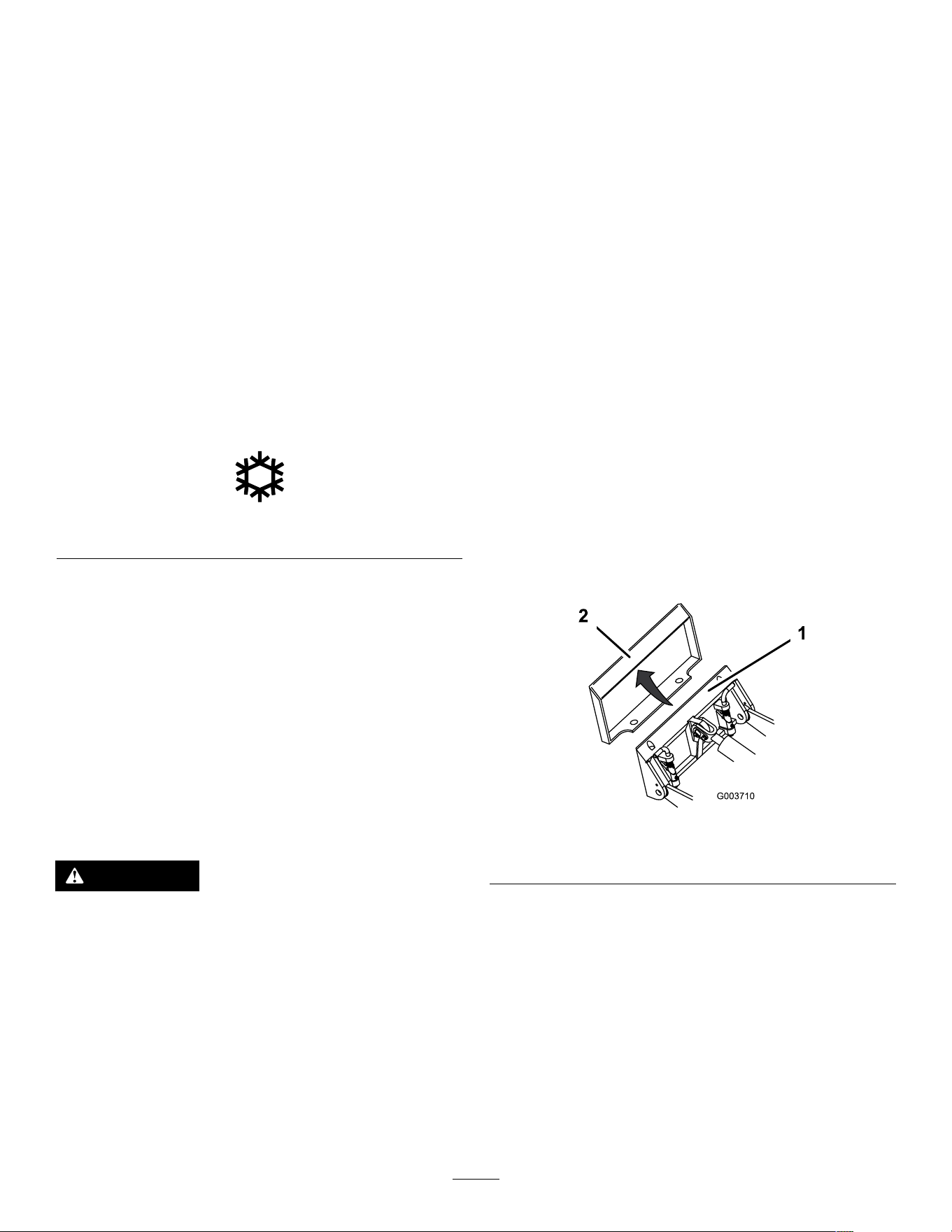
Important: Before installing the attachment,
ensure that the mount plates are free of any dirt
or debris and that the pins move freely . If the pins
do not move freely , grease them.
1. Position the attachment on a level surface with
enough space behind it to accommodate the
machine.
2. Start the machine.
3. T ilt the attachment mount plate forward.
4. Position the mount plate into the upper lip of the
attachment receiver plate.
g003710
Figure 16
1. Mount plate 2. Receiver plate
5. Raise the loader arms while tilting back the
mount plate at the same time.
Important: Raise the attachment enough to
clear the ground and tilt the mount plate all
the way back.
6. Shut of f the machine and remove the key .
7. Engage the quick-attach pins, ensuring that they
are fully seated in the mount plate.
Important: If the pins do not rotate to the
engaged position, the mount plate is not
fully aligned with the holes in the attachment
19
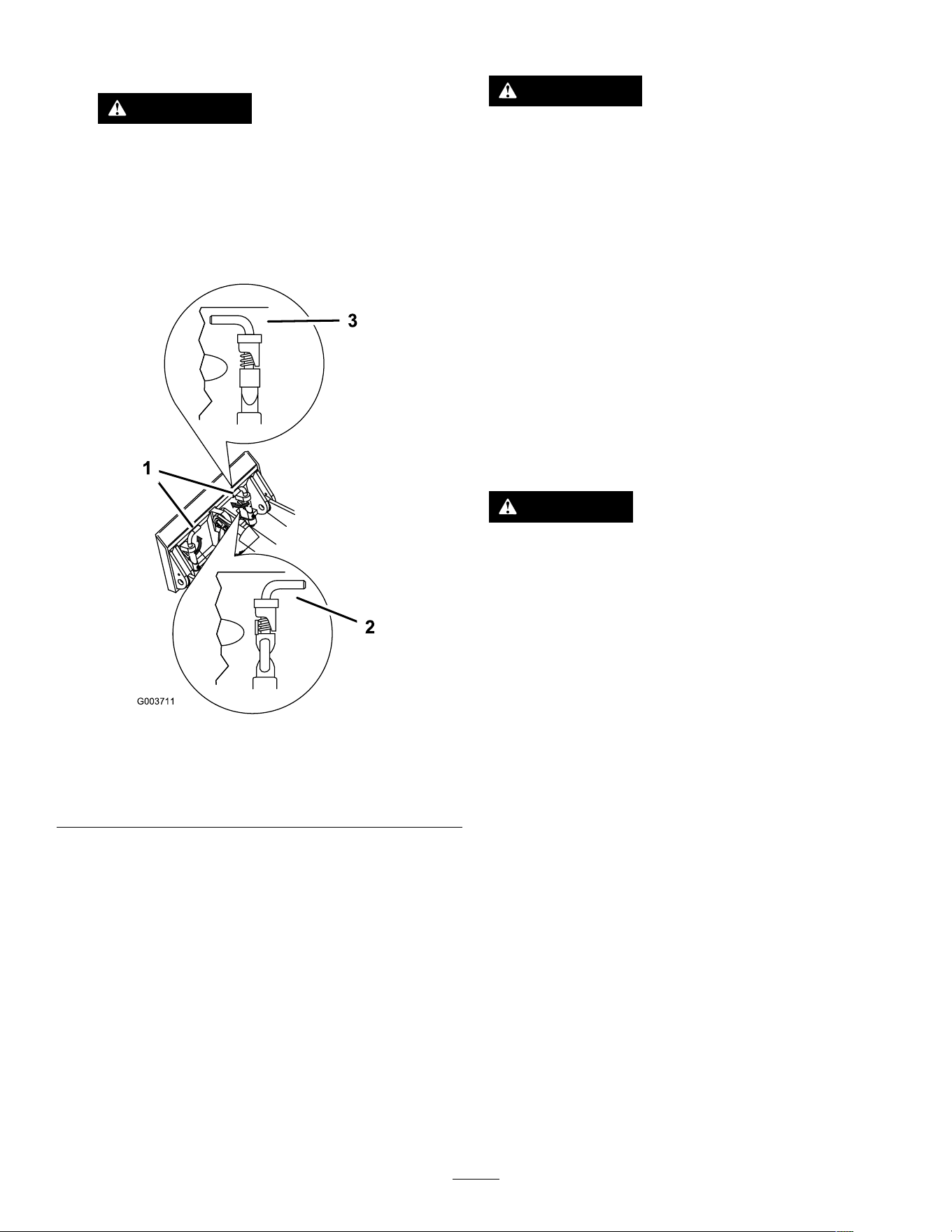
receiver plate. Check the receiver plate and
clean it if necessary .
W ARNING
If you do not fully seat the quick-attach
pins through the attachment mount plate,
the attachment could fall off the machine,
crushing you or bystanders.
Ensure that the quick-attach pins are fully
seated in the attachment mount plate.
g00371 1
Figure 17
1. Quick-attach pins
(engaged position)
3. Engaged position
2. Disengaged position
Connecting the Hydraulic Hoses
W ARNING
Hydraulic uid escaping under pressure can
penetrate skin and cause injury . Fluid injected
into the skin must be surgically removed
within a few hours by a doctor familiar with
this form of injury; otherwise, gangrene may
result.
• Ensure that all hydraulic-uid hoses
and lines are in good condition and all
hydraulic connections and ttings are tight
before applying pressure to the hydraulic
system.
• Keep your body and hands away from
pinhole leaks or nozzles that eject
high-pressure hydraulic uid.
• Use cardboard or paper to nd hydraulic
leaks; never use your hands.
CAUTION
Hydraulic couplers, hydraulic lines/valves,
and hydraulic uid may be hot. If you contact
hot components, you may be burned.
• W ear gloves when operating the hydraulic
couplers.
• Allow the machine to cool before touching
hydraulic components.
• Do not touch hydraulic uid spills.
If the attachment requires hydraulics for operation,
connect the hydraulic hoses as follows:
1. T urn and hold the key in the A UXILIARY HYDRAULIC
RELIEF position and press the auxiliary hydraulic
control switch back and forth to relieve pressure
at the hydraulic couplers.
2. T urn the key to the O FF position and remove
the key .
3. Remove the protective covers from the hydraulic
connectors on the machine.
4. Ensure that all foreign matter is cleaned from
the hydraulic connectors.
5. Push the attachment male connector into the
female connector on the machine.
Note: When you connect the attachment male
connector rst, you relieve any pressure built
up in the attachment.
6. Push the attachment female connector onto the
male connector on the machine.
20
7. Conrm that the connection is secure by pulling
on the hoses.
Removing an Attachment
1. Park the machine on a level surface.
2. Lower the attachment to the ground.
3. If the attachment uses hydraulics, turn and
hold the key in the A UXILIARY HYDRAULIC RELIEF
position and press the auxiliary hydraulic control
switch back and forth to relieve pressure at the
hydraulic couplers.
4. Shut of f the machine and remove the key .
5. Disengage the quick-attach pins by turning them
to the outside.
6. If the attachment uses hydraulics, slide the
collars back on the hydraulic couplers and
disconnect them.
Important: Connect the attachment hoses
together to prevent hydraulic system
contamination during storage.
7. Install the protective covers onto the hydraulic
couplers on the machine.
8. Start the machine, tilt the mount plate forward,
and back the machine away from the attachment.
Changing the Attachment
Mode
1. From the Run screen, press the middle button to
access the Attachment Change screen.
2. Press the middle or right button to switch
between Backhoe or Bucket mode.
Note: Backhoe Mode limits the traction
speed and disables the traction controls when
an operator is in the seat of a backhoe. Bucket
Mode maintains the traction speed.
3. Press the left button to return to the Run screen.
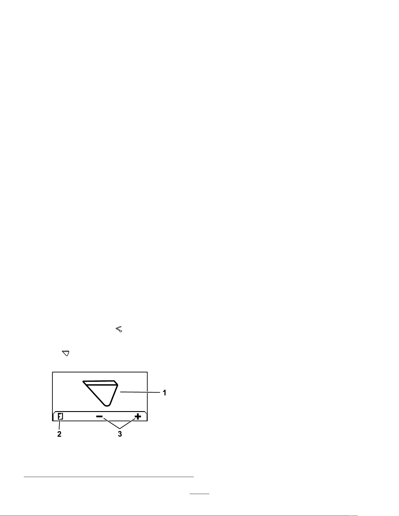
g304809
Figure 18
1. Current attachment mode 3. Change attachment mode
2. Return to Run screen
After Operation
After Operation Safety
General Safety
• Engage the parking brake (if equipped), lower
the loader arms, shut of f the machine, remove
the key , wait for all movement to stop, and allow
the machine to cool before adjusting, cleaning,
storing, or servicing it.
• Clean debris from the attachments and drives to
help prevent res.
• Keep all parts in good working condition and all
hardware tightened.
• Do not touch parts that may be hot from operation.
Allow them to cool before attempting to maintain,
adjust, or service the machine.
• Use care when loading or unloading the machine
into a trailer or truck.
Battery and Charger Safety
• Conrm the voltage that is available in your
country before using the charger .
• Do not charge the machine in a wet environment;
do not get the charger wet; keep it protected from
rain and snow .
• A risk of re, electric shock, or injury may result
from using an accessory not recommended or
sold by T oro.
• T o reduce risk of a battery explosion, follow these
instructions and the instructions for any equipment
that you intend to use near the charger .
• Batteries could emit explosive gasses if they are
signicantly overcharged.
• Refer to an Authorized Service Dealer to service
or replace a battery .
• Never allow children or untrained people to
operate or service the charger . Local regulations
may restrict the age of the operator . The owner
is responsible for training all operators and
mechanics.
• Keep bystanders and children away while
charging.
• W ear appropriate clothing while charging,
including eye protection; long pants; and
substantial, slip-resistant footwear .
• Shut of f the machine and wait until the machine
has completely powered down before charging.
Failure to do this may cause arcing.
• Ensure that the area is well ventilated while
charging.
21
• The charger is for use on only nominal 120 to
240 V AC operation. For use with 240 V circuits,
contact your Authorized Service Dealer for the
correct power cord.
• Do not charge a frozen battery .
• Do not abuse the cord. Do not yank on the power
supply cord to disconnect the charger from the
receptacle. Keep the cord from heat, oil, and
sharp edges.
• Connect the charger directly to a grounding
receptacle. Do not use the charger on an
ungrounded outlet, even with a grounding adapter .
• Do not alter the provided power cord or plug.
• Remove metal items such as rings, bracelets,
necklaces, and watches when working with a
lithium-ion battery . A lithium-ion battery can
produce enough current to cause a severe burn.
• Never operate the charger without good visibility
or light.
• Use an extension cord capable of handling 15 A
or more. If you are charging outdoors, use an
extension cord rated for outdoor use.
• If the power supply cord is damaged while it is
plugged in, disconnect the cord from the wall
receptacle and contact an Authorized Service
Dealer for a replacement.
• Unplug the charger from the electrical outlet when
not in use, before moving it to another location, or
prior to servicing it.
• Do not disassemble the charger . T ake the charger
to an Authorized Service Dealer when service or
repair is required.
• Unplug the power cord from the outlet before
starting any maintenance or cleaning to reduce
risk of electric shock.
• Maintain or replace safety and instruction labels
as needed.
• Do not operate the charger with a damaged cord
or plug. Contact an Authorized Service Dealer to
obtain a replacement cord.
• If the charger has received an impact, been
dropped, or otherwise damaged, do not use it;
take it to an Authorized Service Dealer .
Moving a Non-Functioning
Machine
In an emergency , you can push or tow the machine.
W ARNING
The wheels will spin freely once the gear is
removed; the machine could unintentionally
move and injure you or bystanders.
Do not move the machine on slopes and
install the gear after moving the machine.
1. Shut of f the machine and remove the key .
2. Remove the 2 screws and the cover from the
gearbox.
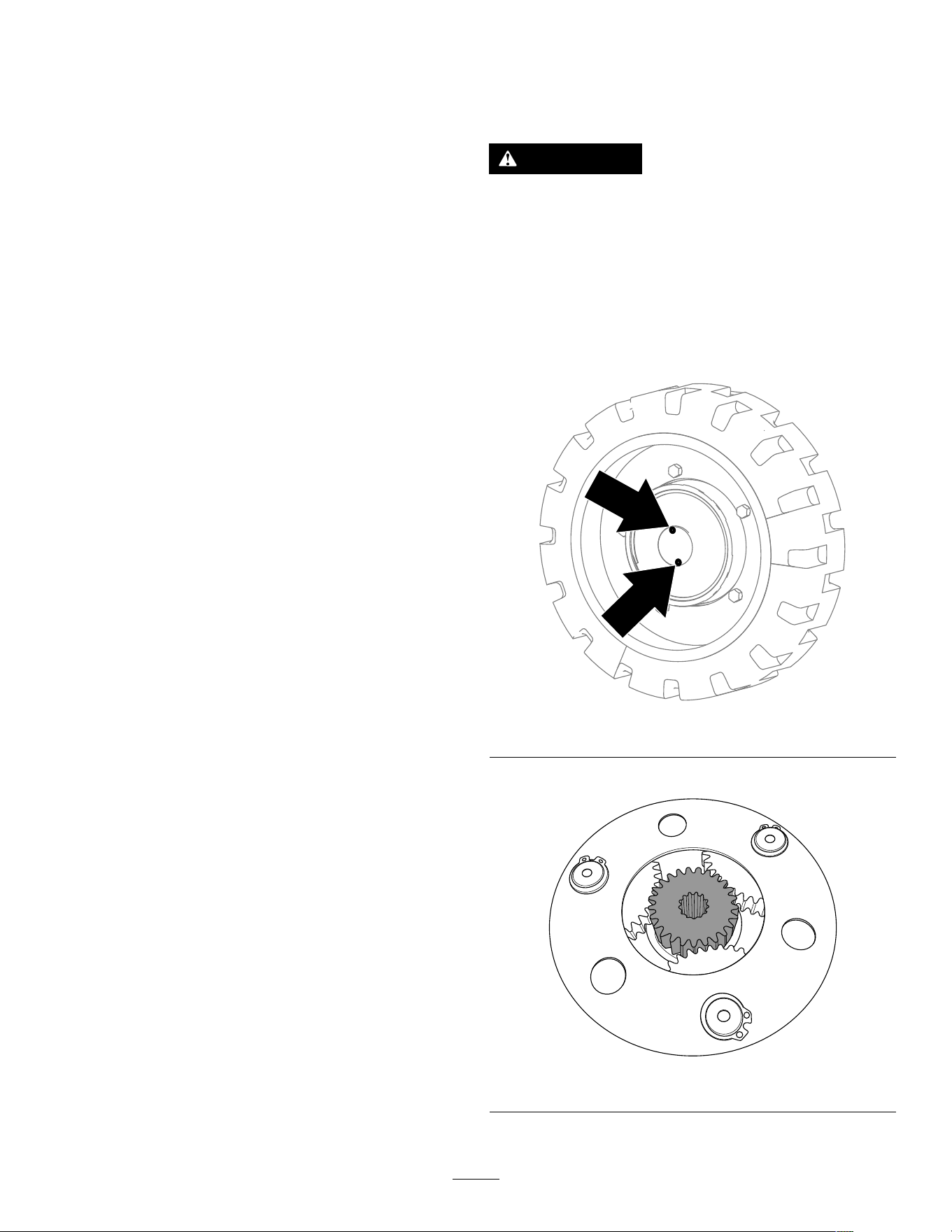
g392174
Figure 19
3. Remove the gear from the gearbox.
g392587
Figure 20
4. Repeat the procedure for the other 3 gearboxes.
22
5. T ow the machine as required using the tie-down
locations.
6. Clean and install the gear and cover for each
gearbox to resume normal operation.
7. T orque the screws to 2.8 to 3.4 N∙m (25 to 30
in-lb).
8. Add gear oil to each motor; refer to Changing
the Drive-Motor Gear Oil ( page 33 ) .
Lifting the Machine
Remove any attachments and lift the machine using
the 4 lift points.
Do not exceed a 30-degree angle when lifting the
machine; use the minimum chain lengths provided
below .
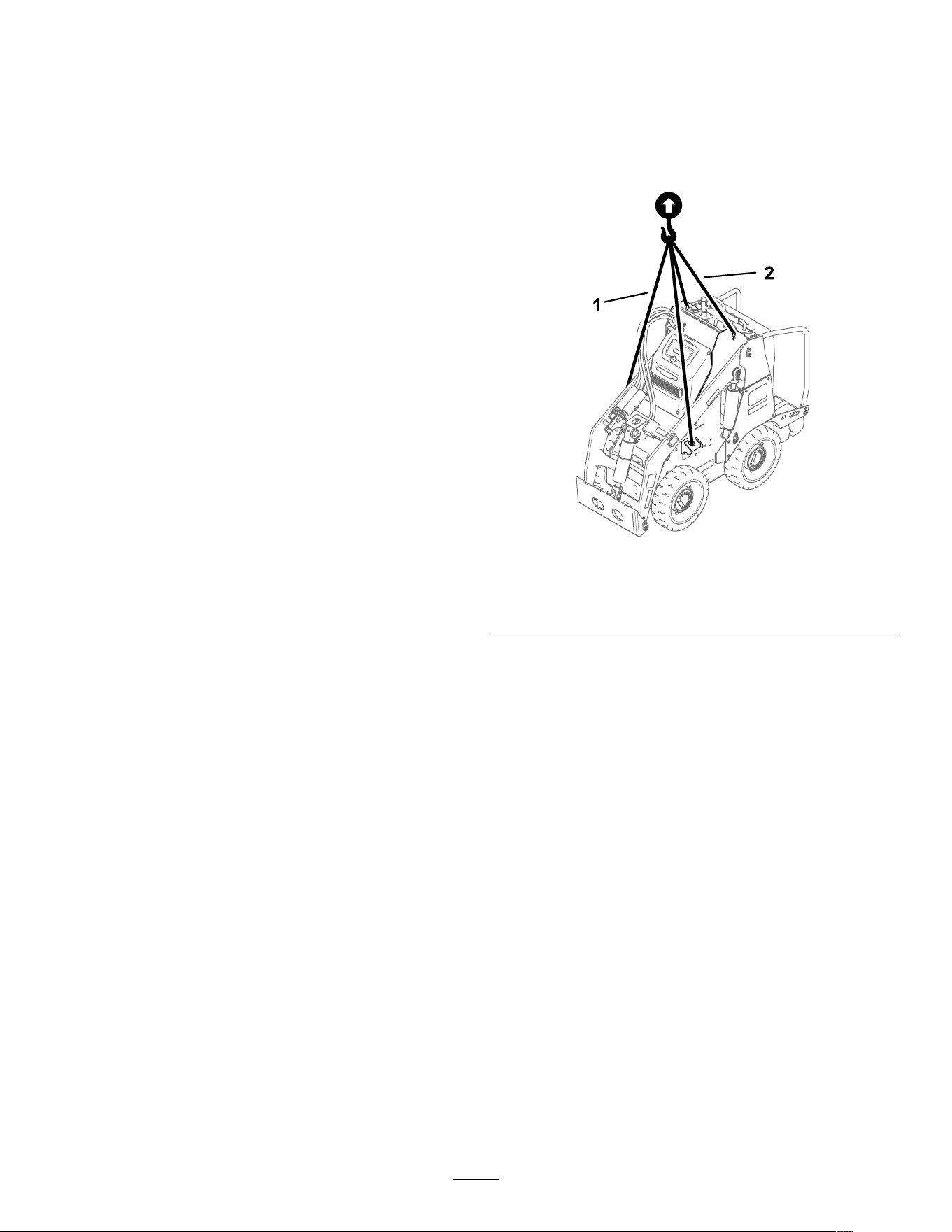
g388352
Figure 21
1. Chain length for front lift point (2)—155 cm (61 inches)
2. Chain length for rear lift point (2)—80 cm (31-1/2 inches)
Hauling the Machine
Use a heavy-duty trailer or truck to haul the machine.
Use a full-width ramp. Ensure that the trailer or truck
has all the necessary brakes, lighting, and marking as
required by law . Please carefully read all the safety
instructions. Knowing this information could help
you or bystanders avoid injury . Refer to your local
ordinances for trailer and tie-down requirements.
23
Loading the Machine
W ARNING
Loading or unloading a machine onto a trailer
or truck increases the possibility of tip-over
and could cause serious injury or death.
• Use extreme caution when operating a
machine on a ramp.
• Load and unload the machine with the
heavy end up the ramp.
• A void sudden acceleration or deceleration
while driving the machine on a ramp as
this could cause a loss of control or a
tip-over situation.
1. If using a trailer , connect it to the towing vehicle
and connect the safety chains.
2. If applicable, connect the trailer brakes.
3. Lower the ramp(s).
4. Lower the loader arms.
5. Load the machine onto the trailer with the heavy
end up the ramp, carrying loads low , as shown.
• If the machine has a full load-bearing
attachment (e.g., bucket) or a
non-load-bearing attachment (e.g.,
trencher), drive the machine forward up the
ramp.
• If the machine has an empty load-bearing
attachment or no attachment, back the
machine up the ramp.
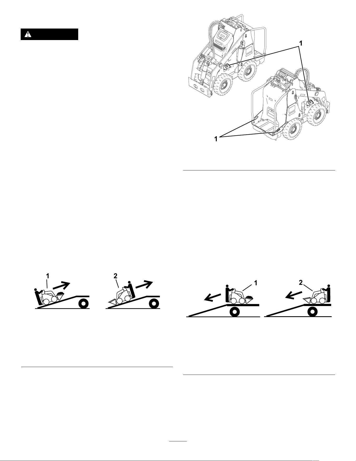
g237904
Figure 22
1. Machine with full
attachment or
non-load-bearing
attachment—drive the
machine forward up the
ramp(s).
2. Machine with empty or
no attachment—back the
machine up the ramp(s).
6. Lower the loader arms all the way down.
7. Engage the parking brake (if equipped), shut of f
the machine, and remove the key .
8. Use the metal tie-down loops on the machine
to securely fasten the machine to the trailer or
truck with straps, chains, cable, or ropes. Refer
to local regulations for tie-down requirements.
g387052
Figure 23
1. T ie-down loops
Unloading the Machine
1. Lower the ramp(s).
2. Unload the machine from the trailer with the
heavy end up the ramp, carrying loads low .
• If the machine has a full load-bearing
attachment (e.g., bucket) or a
non-load-bearing attachment (e.g.,
trencher), back it down the ramp.
• If the machine has an empty load-bearing
attachment or no attachment, drive it forward
down the ramp.
g237905
Figure 24
1. Machine with full
attachment or
non-load-bearing
attachment—back the
machine down the
ramp(s).
2. Machine with empty or
no attachment—drive the
machine forward down the
ramp(s).
24
T ransporting the
Lithium-Ion Batteries
The US Department of T ransportation and
international transportation authorities require that
lithium-ion batteries be transported using special
packaging and only be transported by carriers certied
to haul them. In the US, you are allowed to transport
a battery when it is installed on the machine as
battery powered equipment, with some regulatory
requirements. Contact the US Department of
T ransportation or the appropriate government body in
your country for detailed regulations on transportation
of your batteries or the machine with the batteries
equipped.
For detailed information on shipping a battery , contact
your Authorized Service Dealer .
Charging the Batteries
DANGER
Contact with water while charging the
machine could cause electric shock, causing
injury or death.
• Do not handle the plug or the charger with
wet hands or while standing in water .
• Do not charge the batteries in the rain or in
wet conditions.
T o reduce the risk of electric shock, this charger has a
3-prong grounded plug (type B). If the plug does not
t into the wall receptacle, other grounded plug types
are available; contact an Authorized Service Dealer .
Do not change the charger or the power-supply-cord
plug in any way .
Important: Check the power supply cord
periodically for holes or cracks in the insulation.
Do not use a damaged cord. Do not run the cord
through standing water or wet grass.
Recommended temperature range for charging:
0° to 55°C (32° to 131°F)
Important: Charge the batteries only in
temperatures that are within the recommended
range.
Note: The charger will not function in temperatures
exceeding the minimum or maximum temperatures.
1. Park the machine in the designated location for
charging.
2. Shut of f the machine and remove the key .
3. Ensure that the battery-disconnect switch is in
the O N position.
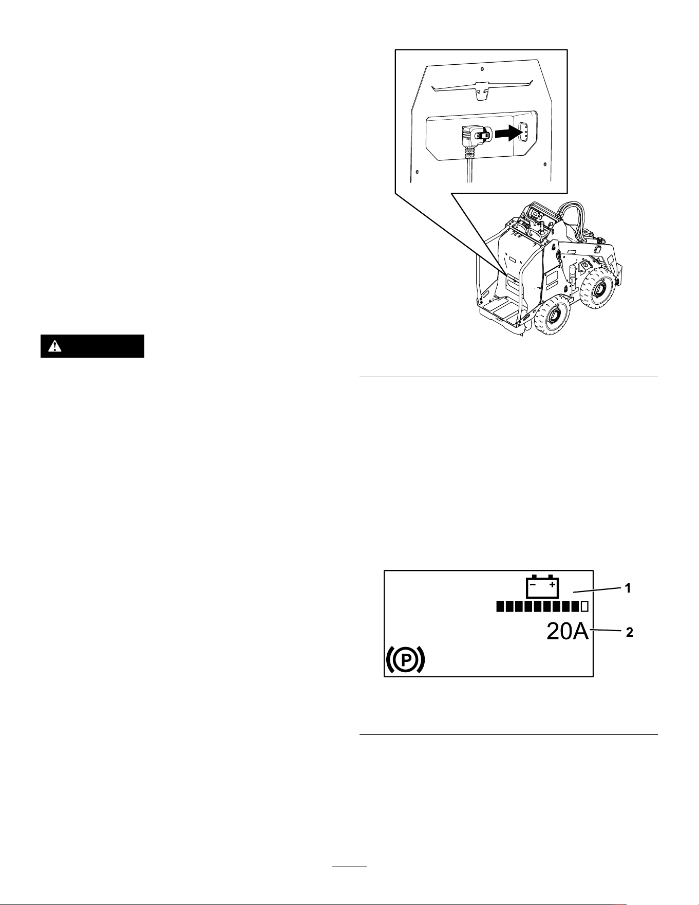
4. Plug the charger cord into the machine.
g388859
Figure 25
5. Plug the other end of the charger cord into a
grounded electrical outlet.
6. Observe the InfoCenter to ensure that the
batteries are charging.
Note: The InfoCenter shows the battery charge
percentage and amperage. Batteries with a
lower voltage charge rst; once they reach
the voltage of the other batteries, all batteries
charge simultaneously . The fan may turn on
while the machine is charging.
When charging is complete, the InfoCenter
shuts of f.
g392265
Figure 26
1. Battery charge 2. Amperage
7. When the machine reaches a suf cient level,
disconnect the charger cord from the outlet.
8. Store the cord in the storage compartment.
9. Start the machine.
10. V erify the charge level using the InfoCenter
display .
25

Maintenance
Note: Determine the left and right sides of the
machine from the normal operating position.
Maintenance Safety
CAUTION
If you leave the key in the switch, someone
could accidently start the machine and
seriously injure you or other bystanders.
Remove the key from the switch before you
perform any maintenance.
• Park the machine on a level surface, disengage
the auxiliary hydraulics, lower the attachment,
ensure that the parking brake is engaged, shut
of f the machine, and remove the key . W ait for all
movement to stop and allow the machine to cool
before adjusting, cleaning, storing, or repairing it.
• Do not allow untrained personnel to service the
machine.
• Use jack stands to support the components when
required.
• Carefully release pressure from components
with stored energy; refer to Relieving Hydraulic
Pressure ( page 34 ) .
• Disconnect the battery before making any repairs;
refer to Using the Battery-Disconnect Switch ( page
30 ) .
• Keep your hands and feet away from the moving
parts. If possible, do not make adjustments with
the machine running.
• Keep all parts in good working condition and all
hardware tightened. Replace all worn or damaged
decals.
• Do not tamper with the safety devices.
• Use only T oro-approved attachments.
Attachments can change the stability and the
operating characteristics of the machine. Y ou may
void the warranty if you use the machine with
unapproved attachments.
• Use only genuine T oro replacement parts.
• If any maintenance or repair requires the loader
arms to be in the raised position, secure the arms
in the raised position with the hydraulic-cylinder
lock(s).
26

Recommended Maintenance Schedule(s)
Maintenance Service
Interval
Maintenance Procedure
After the rst 8 hours
• T orque the wheel-lug nuts.
• Replace the hydraulic lter .
After the rst 50 hours
• Change the drive-motor gear oil.
Before each use or daily
• Grease the machine. (Grease immediately after every washing.)
• Check the static strap; replace it if worn or missing.
• Check the tire treads.
• Remove debris from the machine.
• Check for loose fasteners.
Every 25 hours
• Check the hydraulic lines for leaks, loose ttings, kinked lines, loose mounting
supports, wear , weather , and chemical deterioration.
• Check the hydraulic-uid level.
Every 100 hours
• T orque the wheel-lug nuts.
Every 400 hours
• Replace the hydraulic lter .
Every 500 hours
• Change the drive-motor gear oil.
Every 1,000 hours or
2 years, whichever
comes rst
• Replace all moving hydraulic hoses.
Y early
• Change the hydraulic uid.
Y early or before storage
• T ouch up chipped paint.
27
Pre-Maintenance
Procedures
Using the Cylinder Locks
W ARNING
The loader arms may lower when in the raised
position, crushing anyone under them.
Install the cylinder lock(s) before performing
maintenance that requires raised loader arms.
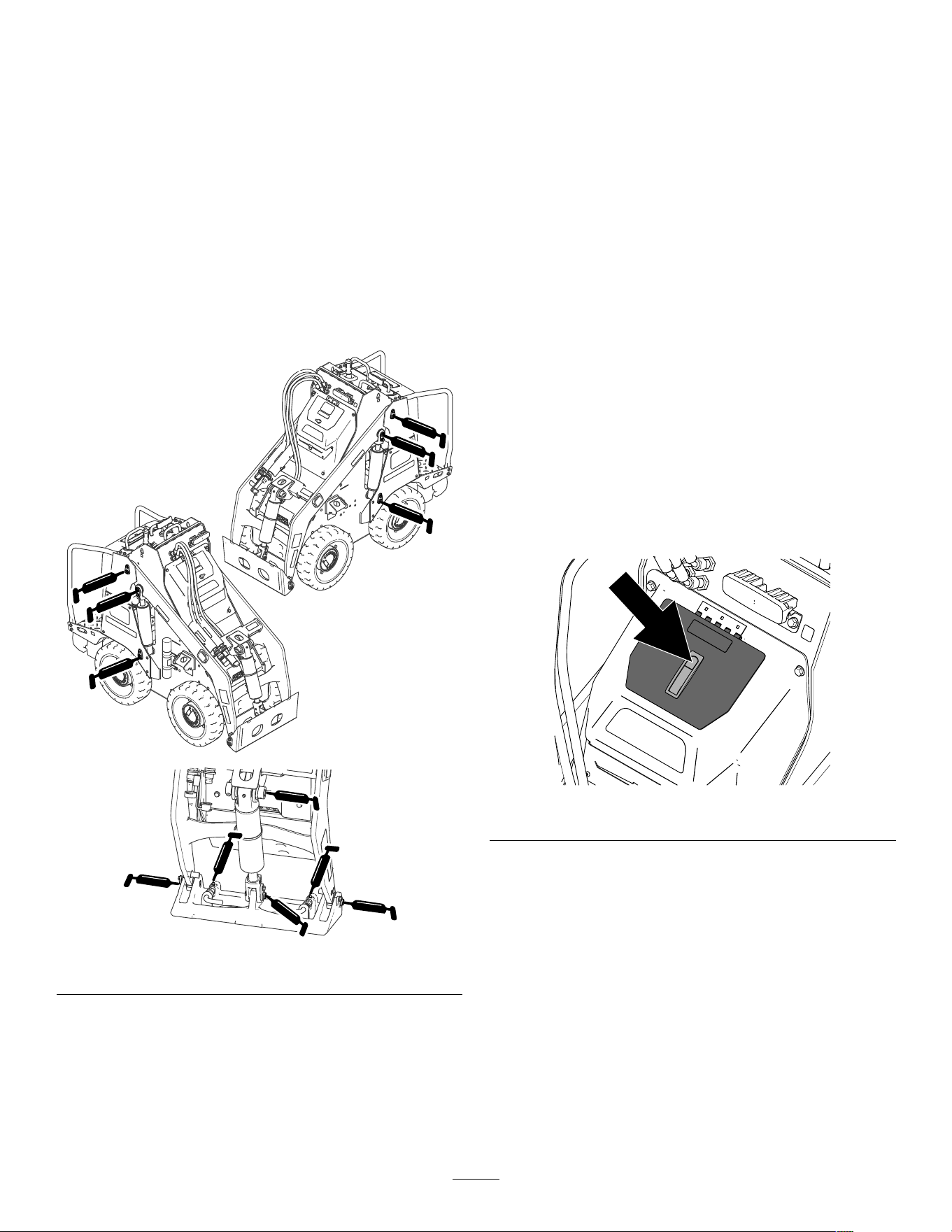
Installing the Cylinder Locks
1. Remove the attachment.
2. Raise the loader arms to the fully raised position.
3. Shut of f the machine and remove the key .
4. Position a cylinder lock over each lift-cylinder
rod.
g421593
Figure 27
1. Cylinder lock 3. Lift-cylinder rod
2. Pin (2)
5. Secure each cylinder lock with 2 pins.
6. Slowly lower the loader arms until the cylinder
locks contact the cylinder bodies and rod ends.
Removing and Storing the
Cylinder Locks
Important: Remove the cylinder locks from the
rods and fully secure them in the storage position
before operating the machine.
1. Start the machine.
2. Raise the loader arms to the fully raised position.
3. Shut of f the machine and remove the key .
4. Remove the pins securing each cylinder lock.
5. Remove the cylinder locks.
6. Place the cylinder locks on the posts on the
sides of the machine and secure with the pins.
7. Lower the loader arms.
28
Accessing Internal
Components
W ARNING
Opening or removing covers, hoods, and
screens while the machine is running could
allow you to contact moving parts, seriously
injuring you.
Before opening any of the covers, hoods, and
screens, shut off the machine, remove the key
from the key switch, and allow the machine
to cool.
W ARNING
The rotating fan can cause personal injury .
• Do not operate the machine without guards
in place.
• Keep your ngers, hands, and clothing
clear of the rotating fan.
• Shut off the machine and remove the key
before performing maintenance.
Removing the Hood
1. Park the machine on a level surface.
2. Shut of f the machine, remove the key , and wait
for moving parts to stop.
3. Remove the 4 bolts (3/8 x 1-1/2 inches) securing
the hood.
g387431
Figure 28
4. Pull the hood of f the machine.
Reverse the procedure to install the hood.
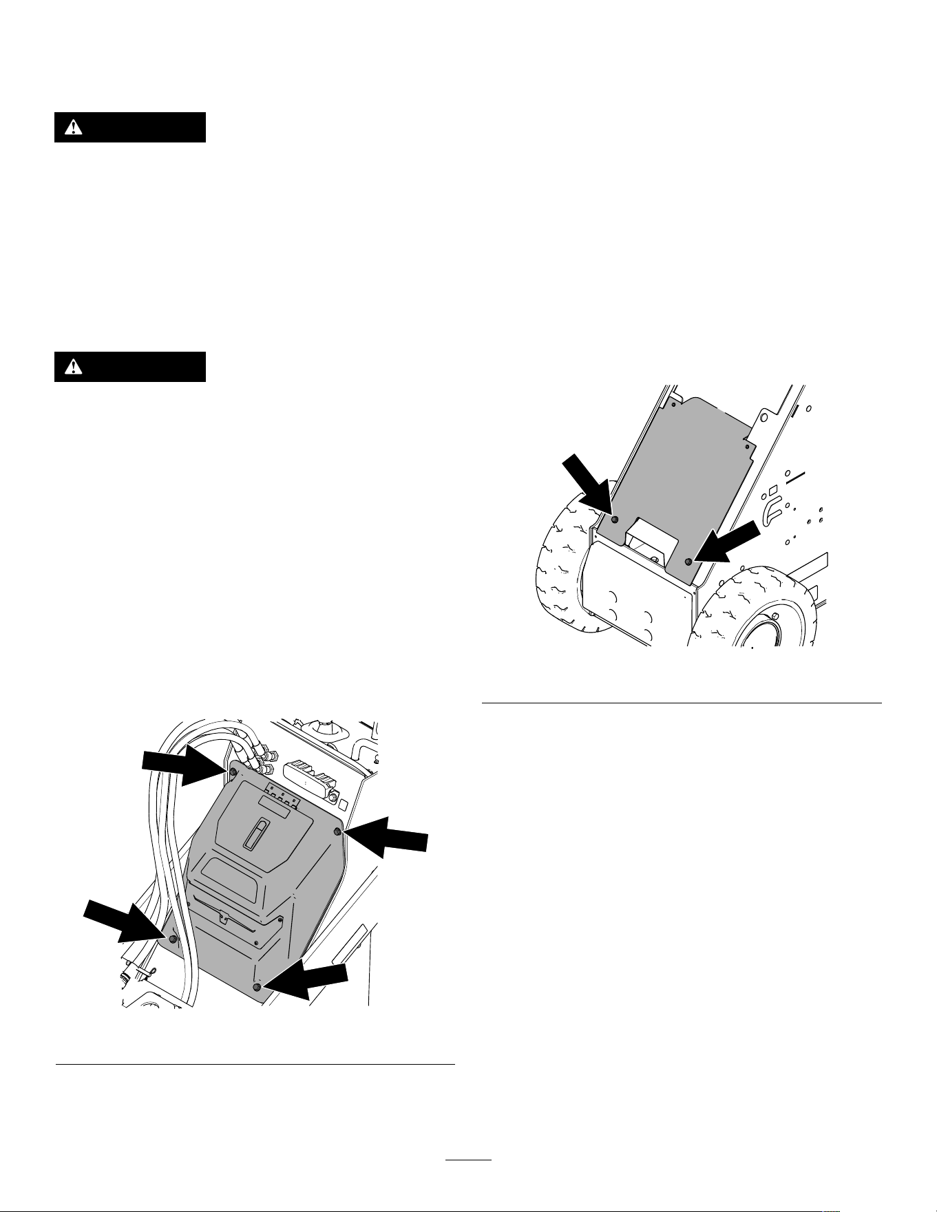
Removing the Lower Front
Cover
1. Park the machine on a level surface.
2. Raise the loader arms and install the cylinder
locks.
Note: If you cannot raise the loader arms using
the machine power , pull the loader-arm lever
rearward and use a hoist to lift the loader arms
at their lift points.
3. Shut of f the machine, remove the key , and wait
for moving parts to stop.
4. Remove the hood.
5. Remove the 2 bolts (3/8 x 1 inch) securing the
cover .
g387443
Figure 29
6. Remove the cover .
Reverse the procedure to install the cover .
29
Lubrication
Greasing the Machine
Service Interval : Before each use or daily (Grease
immediately after every washing.)
Grease T ype: General-purpose grease
1. Park the machine on a level surface and lower
the loader arms.
2. Shut of f the machine and remove the key .
3. Clean the grease ttings with a rag.
4. Connect a grease gun to each tting.
g392673
Figure 30
5. Pump grease into the ttings until grease begins
to ooze out of the bearings (approximately 3
pumps).
6. Wipe up any excess grease.
Electrical System
Maintenance
Electrical System Safety
• Disconnect the battery before making any repairs;
refer to Using the Battery-Disconnect Switch ( page
30 ) .
• Charge the battery in an open, well-ventilated
area, away from sparks and ames. Unplug the
charger before connecting or disconnecting the
battery . W ear protective clothing and use insulated
tools.
Using the
Battery-Disconnect Switch
1. Park the machine on a level surface and lower
the loader arms.
2. Shut of f the machine and remove the key .
3. Push the button on the latch and open the hood
cover .
g388891
Figure 31
4. T urn the battery-disconnect switch to the ON or
OFF position to perform the following:
• T o energize the machine electrically , rotate
the battery-disconnect switch clockwise to
the ON position.
• T o de-energize the machine electrically ,
rotate the battery-disconnect switch
counterclockwise to the OFF position.
30
g387539
Figure 32
1. Battery-disconnect
switch— O FF position
2. Battery-disconnect
switch— O N position
5. Close the cover and push the latch down.
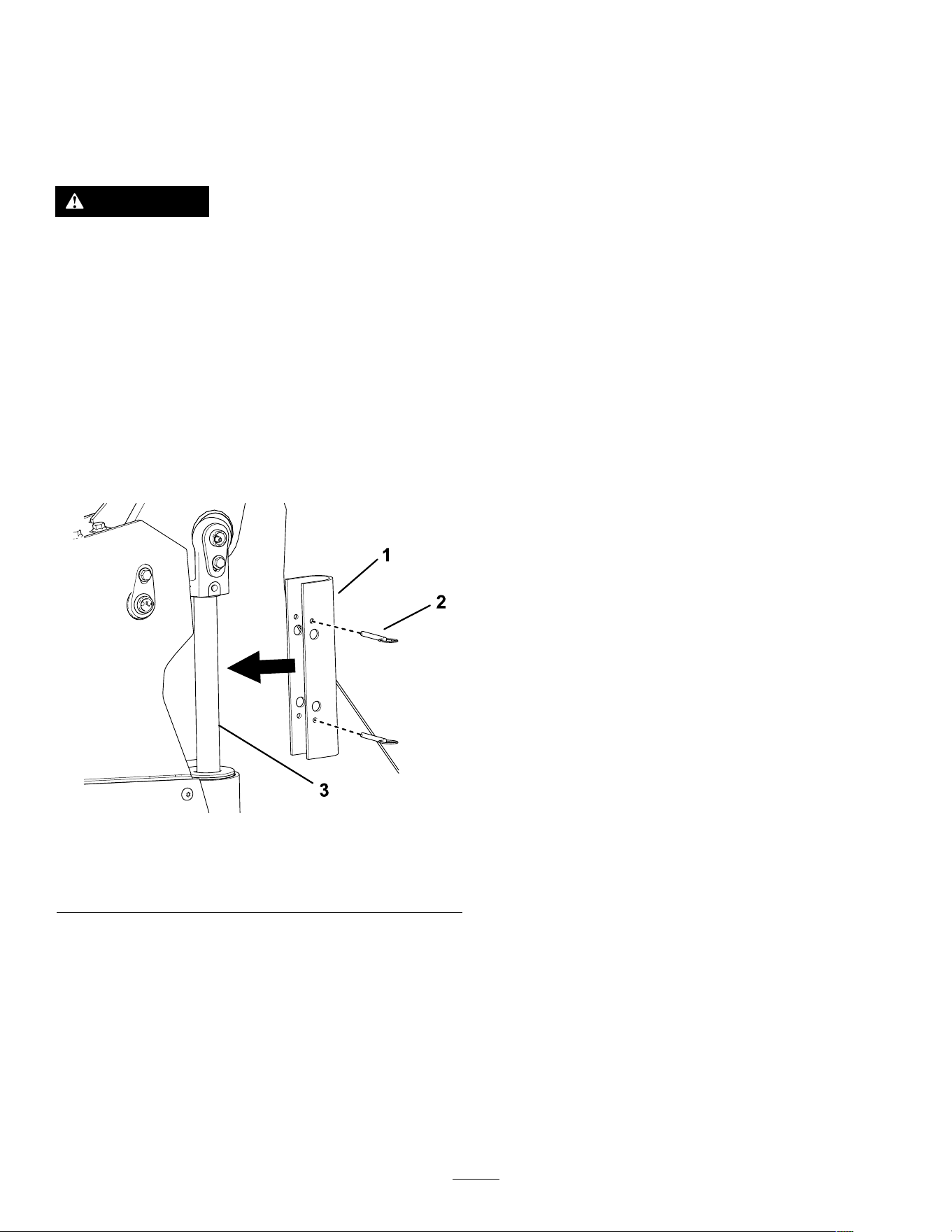
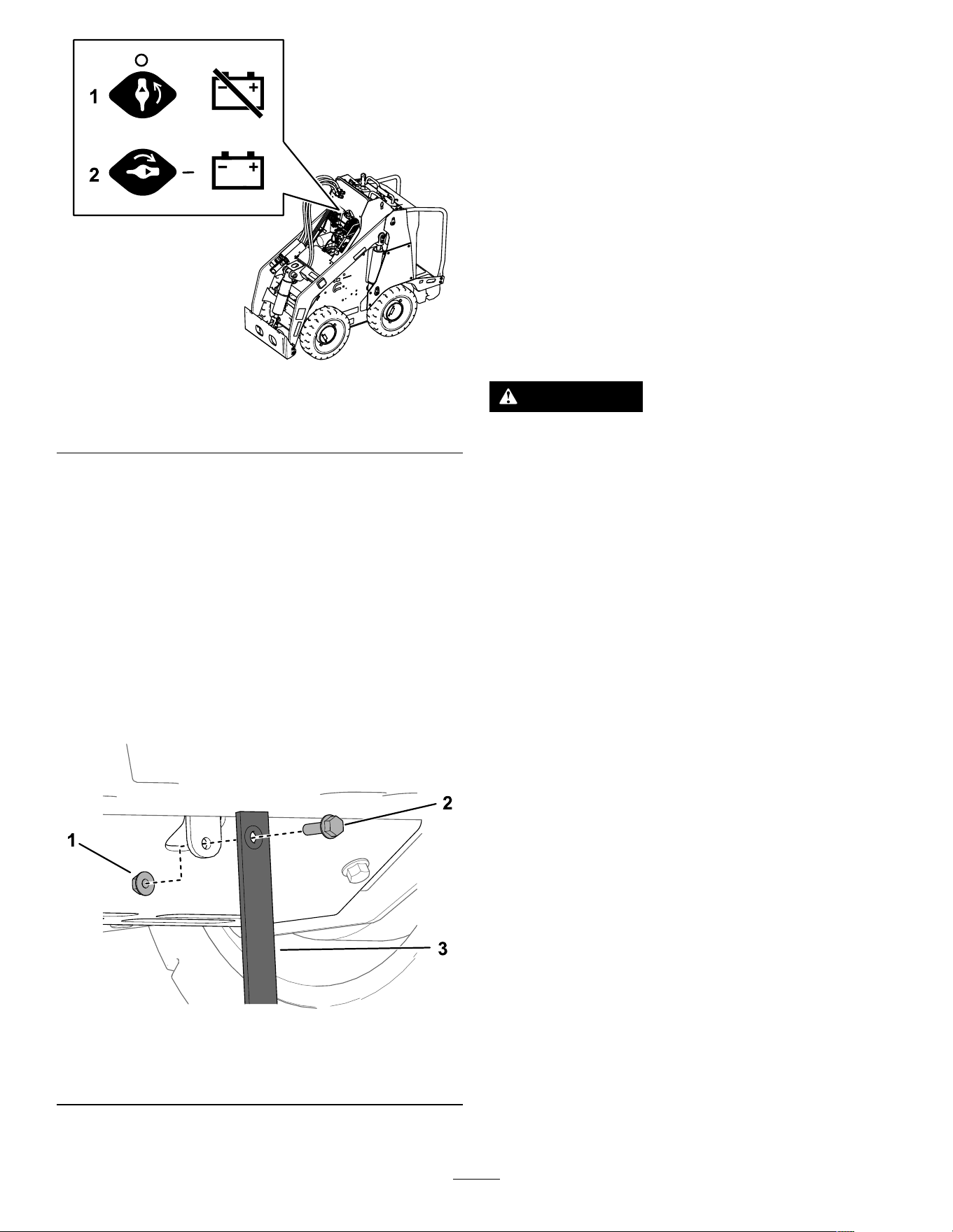
Replacing the Static Strap
Service Interval : Before each use or daily —Check
the static strap; replace it if worn or
missing.
1. Park the machine on a level surface and lower
the loader arms.
2. Shut of f the machine and remove the key .
3. Under the platform, replace the static strap as
shown.
g387663
Figure 33
1. Nut
3. Static strap
2. Bolt
Servicing the Batteries
Note: The machine is equipped with 6 lithium-ion
batteries.
A lithium-ion battery must be disposed of or recycled
in accordance with local and federal regulations. If
a battery requires service, contact your Authorized
Service Dealer for assistance.
Do not open the battery . If you are having problems
with a battery , contact your Authorized Service Dealer
for assistance.
Maintaining the Lithium-Ion
Batteries
W ARNING
The batteries contain high voltage, which
could burn or shock you.
• Do not attempt to open the batteries.
• Use extreme care when handling a battery
with a cracked case.
• Use only the charger designed for the
batteries.
The lithium-ion batteries hold a suf cient charge to
perform intended work during its life span.
T o achieve maximum life and use from your batteries,
follow these guidelines:
• Do not open the battery .
• Store/park the machine in a clean, dry garage or
storage area, away from direct sunlight, heat
sources, rain, and wet conditions. Do not store
it in a location where the temperature exceeds the
range specied in Battery Storage Requirements
( page 39 ) .
Important: T emperatures outside of this range
will damage your batteries. High temperatures
during storage, especially at a high state of
charge, reduces the life of the batteries.
• When storing the machine for more than 10 days,
ensure that the machine is in a cool and dry
location, out of sunlight, rain, and wet conditions.
• If you are using the machine hot conditions or in
strong, direct sunlight, the battery may overheat.
If this happens, a high-temperature alert appears
on the InfoCenter and machine functionality may
be reduced.
31
Immediately drive the machine to a cool location
out of the sun, turn of f the machine, and allow the
batteries to cool fully before resuming operation.
If the batteries continue to overheat, another alert
appears on the InfoCenter and the machine will
shut of f.
• Use lights only when it is necessary .
Maintaining the Battery
Charger
Important: All electrical repairs should be
performed by an Authorized Service Dealer only .
The operator can perform very little maintenance other
than protecting the charger from damage and weather .
• Clean the charger cord with a slightly damp cloth
after each use.
• Coil the cord and place it into the storage
compartment when not in use.
• Periodically examine the cord for damage, and
replace them when necessary with T oro-approved
parts.
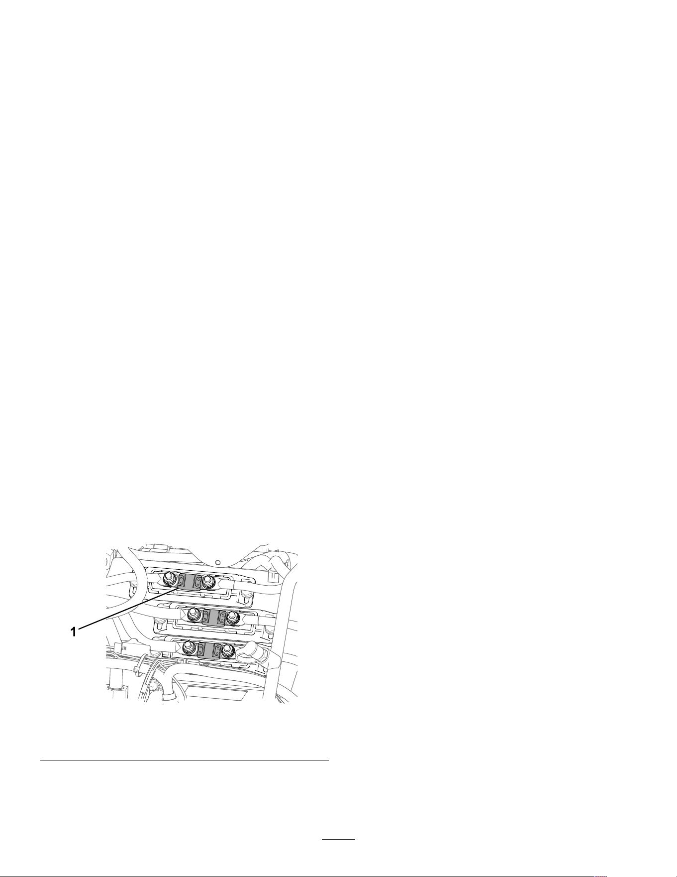
Servicing the Fuses
1. Park the machine on a level surface.
2. Shut of f the machine and remove the key .
3. Remove the hood; refer to Removing the Hood
( page 29 ) .
4. T urn the battery-disconnect switch to the O FF
position.
5. T est or replace the fuses as described in the
Service Manual for the machine.
g390518
Figure 34
1. Fuse—200 A (3)
6. T urn the battery-disconnect switch to the O N
position.
7. Install the hood.
Drive System
Maintenance
Checking the T ire T reads
Service Interval : Before each use or daily
Check the tire treads for wear . Replace the tires when
the treads are worn and shallow .
Checking the Wheel-Lug
Nuts
Service Interval : After the rst 8 hours
Every 100 hours
Check and torque the wheel lug nuts 61 to 75 N∙m
(45 to 55 ft-lb).
Drive-Motor Gear Oil
Specications
Oil type: Mobil 626 SHC
Capacity: 0.31 L (10.5 oz) per gearbox
32
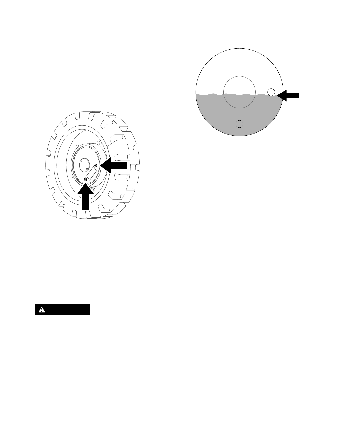
Changing the Drive-Motor
Gear Oil
Service Interval : After the rst 50 hours
Every 500 hours
1. Start the machine and drive it for 5 minutes.
Note: This warms the gear oil so that it drains
better .
2. Park the machine on a level surface so that
a drain plug on the motor is in the 6 o’clock
position.
g387302
Figure 35
3. Shut of f the machine and remove the key .
4. Raise the machine of f the ground so that the
wheels are of f the ground. Support the machine
using jack stands.
Note: Use jack stands rated for your machine.
Refer to the Specications ( page 16 ) for the
weight.
W ARNING
Mechanical or hydraulic jacks may fail to
support the machine and cause serious
injury .
Use jack stands when supporting the
machine.
5. Remove the rear wheels.
6. Place a drain pan under the drive motor .
7. Remove both plugs and allow the gear oil to
drain.
8. Install the lower plug.
9. Fill the drive motor with gear oil through the open
hole until the oil is up to the bottom of the hole.
Note: Y ou may not need the full capacity
amount due to residual oil in the motor .
g387301
Figure 36
10. Install the plug.
1 1. Repeat the procedure for the other drive motors.
12. Start the machine and engage the traction
control it for a few minutes.
13. Stop the machine so that a drain plug on each
motor is in the 3 o’clock position, shut of f the
machine, and remove the key .
14. Remove the plug in the 3 o’clock position, and
verify that the oil level is at the bottom of the
hole. Add oil as needed.
15. Install the plug and torque all plugs to 5 to 6 N∙m
(50 to 60 in-lb).
16. Install the tires and torque the lug nuts 61 to 75
N∙m (45 to 55 ft-lb).
17. Lower the machine to the ground.
33
Controls System
Maintenance
Adjusting the Controls
The factory adjusts the controls before shipping the
machine. However , after many hours of use, you
may need to adjust the traction control alignment,
the N EUTRAL position of the traction control, and the
tracking of the traction control in the full forward
position.
Contact your Authorized Service Dealer to adjust the
controls of your machine.
Hydraulic System
Maintenance
Hydraulic System Safety
• Seek immediate medical attention if uid is injected
into skin. Injected uid must be surgically removed
within a few hours by a doctor .
• Ensure that all hydraulic-uid hoses and lines are
in good condition and all hydraulic connections
and ttings are tight before applying pressure to
the hydraulic system.
• Keep your body and hands away from pinhole
leaks or nozzles that eject high-pressure hydraulic
uid.
• Use cardboard or paper to nd hydraulic leaks.
• Safely relieve all pressure in the hydraulic system
before performing any work on the hydraulic
system.
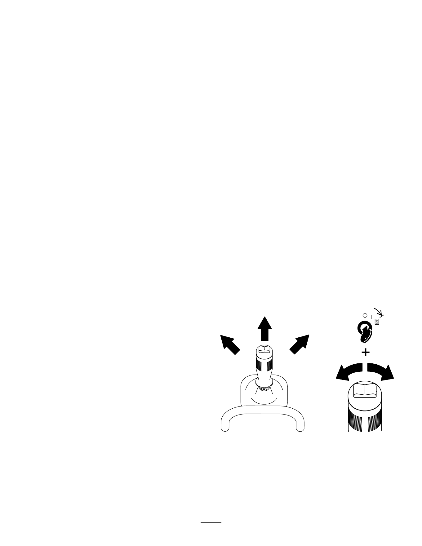
Relieving Hydraulic
Pressure
T o relieve hydraulic pressure while the machine
is on, disengage the auxiliary hydraulics and fully
lower the loader arms. T urn the key switch to the
A UXILIARY HYDRAULIC RELIEF position and press the
auxiliary-hydraulic switch back and forth.
g393575
Figure 37
34

T o relieve the pressure on the loader arms and
attachment plate while the machine is of f, cycle the
joystick between the forward positions to lower the
loader arms.
g387836
Figure 38
Hydraulic Fluid
Specications
Hydraulic T ank Capacity: 22.7 L (6 US gallons)
Recommended hydraulic uid: T oro PX Extended
Life Hydraulic Fluid
Note: A machine using the recommended
replacement uid requires less frequent uid and lter
changes.
Alternative hydraulic uids: If T oro PX Extended
Life Hydraulic Fluid is not available, you may use
another conventional, petroleum-based hydraulic uid
having specications that fall within the listed range
for all the following material properties and that it
meets industry standards. Do not use synthetic uid.
Consult with your lubricant distributor to identify a
satisfactory product.
Note: T oro does not assume responsibility for
damage caused by improper substitutions, so use
products only from reputable manufacturers who will
stand behind their recommendation.
High V iscosity Index/Low Pour Point
Anti-wear Hydraulic Fluid, ISO VG 46
Material Properties:
V iscosity , ASTM D445 cSt @ 40°C (104°F)
44 to 48
V iscosity Index ASTM D2270
140 or higher
Pour Point, ASTM D97 -37°C to -45°C (-34°F
to -49°F)
Industry Specications: Eaton V ickers 694 (I-286-S,
M-2950-S/35VQ25 or
M-2952-S)
Note: Many hydraulic uids are almost colorless,
making it dif cult to spot leaks. A red dye additive for
the hydraulic uid is available in 20 ml (0.67 oz)
bottles. A bottle is suf cient for 15 to 22 L (4 to 6 US
gallons) of hydraulic uid. Order Part No. 44-2500
from your Authorized Service Dealer .
35
Checking the
Hydraulic-Fluid Level
Service Interval : Every 25 hours
Check the hydraulic-uid level before the machine is
rst started and after every 25 operating hours.
Refer to Hydraulic Fluid Specications ( page 35 ) .
Important: Always use the correct hydraulic
uid. Unspecied uids will damage the hydraulic
system.
1. Park the machine on a level surface, remove
any attachment, raise the loader arms, and
install the cylinder locks.
2. Shut of f the machine, remove the key , and allow
the machine to cool.
3. Remove the hood and lower front cover .
4. Clean the area around the ller neck of the
hydraulic tank.
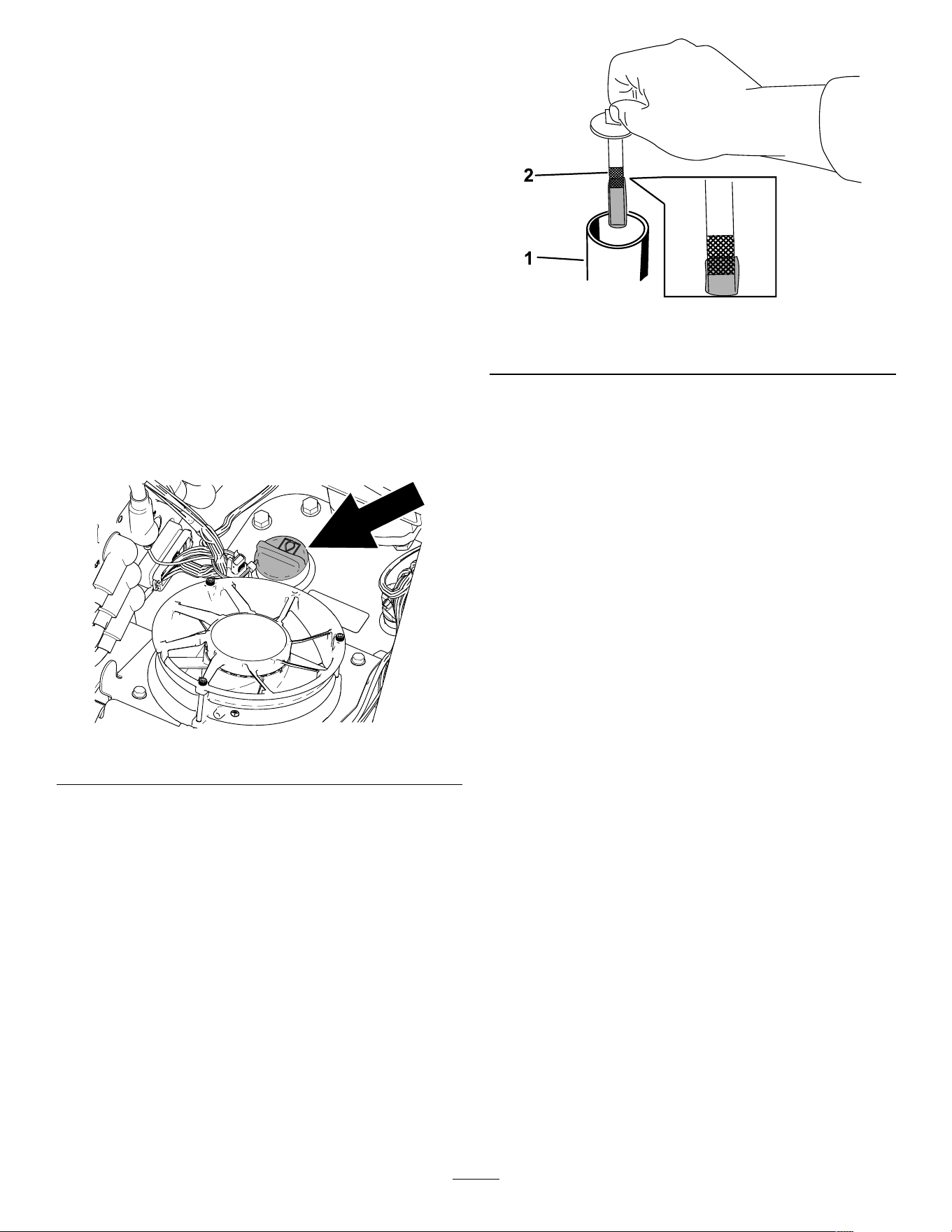
g390547
Figure 39
5. Remove the ller-neck cap and check the uid
level on the dipstick.
The uid level should be between the marks on
the dipstick.
g421601
Figure 40
1. Filler neck cap 2. Dipstick
6. If the level is low , add enough uid to raise it to
the proper level.
7. Install the ller-neck cap.
8. Install the lower front cover and hood.
9. Remove and store the cylinder locks and lower
the loader arms.
36
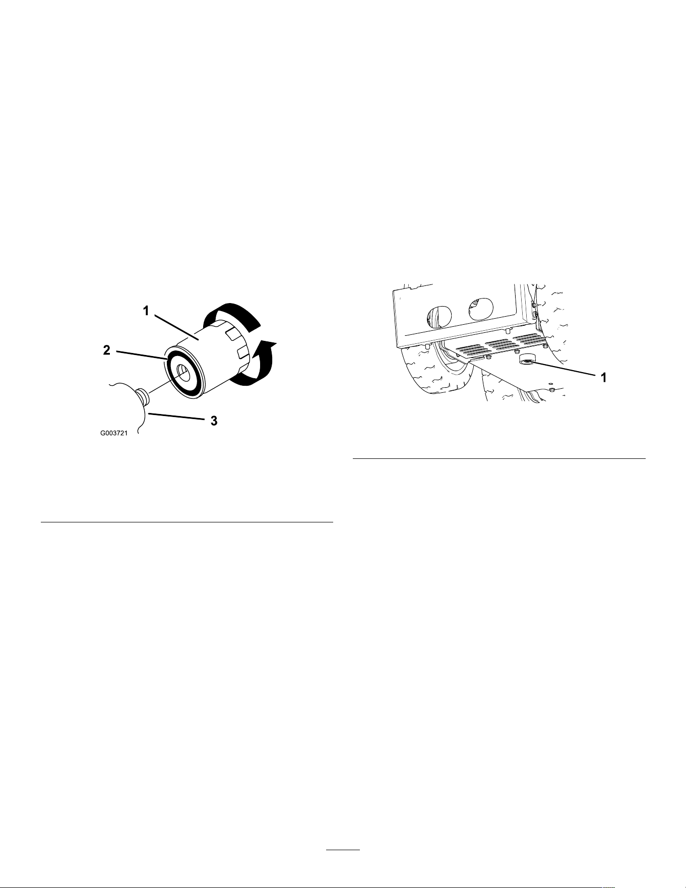
Replacing the Hydraulic
Filter
Service Interval : After the rst 8 hours
Every 400 hours
Important: Do not substitute an automotive oil
lter; otherwise, severe hydraulic system damage
may result.
1. Park the machine on a level surface and lower
the loader arms.
2. Shut of f the machine and remove the key .
3. Remove the hood and lower front cover .
4. Place a drain pan under the lter .
5. Remove the old lter ( Figure 41 ) and wipe the
surface of the lter adapter clean.
g003721
Figure 41
1. Hydraulic lter
2. Gasket
3. Filter adapter
6. Apply a thin coat hydraulic uid to the rubber
gasket on the replacement lter ( Figure 41 ).
7. Install the replacement hydraulic lter onto the
lter adapter ( Figure 41 ). T ighten it clockwise
until the rubber gasket contacts the lter adapter ,
then tighten the lter an additional 1/2 turn.
8. Clean up any spilled uid.
9. Start the machine and let it run for about 2
minutes to purge air from the system.
10. Shut of f the machine and check for leaks.
1 1. Check the uid level in the hydraulic tank; refer
to Checking the Hydraulic-Fluid Level ( page 36 ) .
Add uid to raise the level to mark on dipstick.
Do not overll the tank.
12. Install the lower front cover and hood.
Changing the Hydraulic
Fluid
Service Interval : Y early
1. Park the machine on a level surface, remove
any attachment, raise the loader arms, and
install the cylinder locks.
2. Shut of f the machine and remove the key .
3. Remove the hood and lower front cover .
4. Place a large drain pan under the machine that
can hold the uid capacity listed in Hydraulic
Fluid Specications ( page 35 ) .
5. Remove the drain plug from the bottom of the
hydraulic tank and allow the uid to completely
drain ( Figure 42 ).
g387955
Figure 42
1. Drain plug
6. Install the drain plug.
7. Fill the hydraulic tank with hydraulic uid; refer
to Hydraulic Fluid Specications ( page 35 ) .
Note: Dispose of used uid at a certied
recycling center .
8. Install the lower front cover and the hood.
9. Remove and store the cylinder locks and lower
the loader arms.
37

Cleaning
Removing Debris
Service Interval : Before each use or daily
W ARNING
Using compressed air improperly to clean the
machine could result in serious injury .
• W ear appropriate personal protective
equipment, such as eye protection, hearing
protection, and a dust mask.
• Do not aim compressed air at any part of
your body or at anyone else.
• Refer to the manufacturer ’ s instructions
for the air compressor for operating and
safety information.
1. Park the machine on a level surface, remove
any attachment, raise the loader arms, and
install the cylinder locks.
2. Shut of f the machine and remove the key .
3. Clean any debris from the machine.
Important: Blow the dirt out rather than
wash it out. If you use water , keep it away
from electrical items and hydraulic valves.
Clean electrical connectors using
compressed air; do not use contact cleaner .
4. Remove and store the cylinder locks and lower
the loader arms.
W ashing the Machine
If you must pressure wash the machine, do the
following:
Important: Do not clean the machine with water
while it is charging. Ensure machine is dry before
charging.
• W ear appropriate personal protective equipment
for the pressure washer .
• Keep all guards in place on the machine.
• A void spraying at electronic components.
• A void spraying at edges of decals.
• Spray the exterior of the machine only . Do not
spray directly into openings in the machine.
• Spray only the dirty parts of the machine.
• Use a 40-degree or larger spray nozzle. 40-degree
nozzles are usually white.
• Keep the tip of the pressure washer at least 61 cm
(2 ft) away from the surface being washed.
• Use only pressure washers with pressure below
13790 kpa (2000 psi) and ow below 7.6 L (2 US
gallons) per minute.
• Replace damaged or peeling decals.
• Grease all grease points after washing; refer to
Greasing the Machine ( page 30 ) .
38

Storage
Storage Safety
• Shut of f the machine, remove the key , wait for all
moving parts to stop, and allow the machine to
cool before storing it.
• Do not store the machine near ames.
Storing the Machine
1. Park the machine on a level surface and lower
the loader arms.
2. Shut of f the machine and remove the key .
3. Remove dirt and grime from the external parts
of the entire machine.
Important: W ash the machine using mild
detergent and water . A void excessive use
of water , especially near the control panel,
hydraulic pumps, and motors.
4. Grease the machine; refer to Greasing the
Machine ( page 30 ) .
5. T orque the wheel lug nuts; refer to Checking the
Wheel-Lug Nuts ( page 32 ) .
6. Check the hydraulic uid level; refer to Checking
the Hydraulic-Fluid Level ( page 36 ) .
7. Check and tighten all fasteners. Repair or
replace any worn, damaged, or missing parts.
8. Paint all scratched or bare metal surfaces with
paint available from your Authorized Service
Dealer .
9. Store the machine in a clean, dry garage or
storage area. Remove the key from the key
switch and keep it in a memorable place.
10. For prolonged storage, follow the battery
storage requirements; refer to Battery Storage
Requirements ( page 39 ) .
1 1. Cover the machine to protect it and keep it clean.
Battery Storage
Requirements
Note: Y ou do not need to remove the batteries from
the machine for storage.
Refer to the temperature limits for storage in the
following table:
T emperature Limits for Storage
Storage T emperature Appropriate Storage T ime
45° to 55°C (1 13° to 131°F)
1 week
25° to 45°C (77° to 1 13°F)
3 weeks
-20° to 25°C (-4° to 77°F)
52 weeks
Important: T emperatures outside of these ranges
will damage your batteries.
The temperature that the batteries are stored
at will affect their long-term life. Storage for
long periods of time at extreme temperatures
will reduce the battery life. For temperatures
above 25°C (77°F), only store the machine for the
appropriate amount of time indicated in the table.
• Before you store the machine, charge or discharge
the batteries between 40% to 60% (54.3V to
57.3V).
Note: A 50% charge is optimal to ensure a
maximum battery life. When the batteries are
charged to 100% before storage, the battery life
shortens.
If you anticipate that the machine will be stored
for a longer period of time, charge the batteries
to around 60%.
• For every 6 months of storage, check the
battery-charge level and ensure that it is between
40% to 60%. If the charge is below 40%, charge
the batteries between 40% to 60%.
• Y ou can use a multimeter to check the charge level
when the machine is of f. Refer to the following
table for the amount of voltage that is equal to the
charge level:
V oltage
Charge Level
57.3V
60%
55.4V
50%
54.3V
40%
• After charging the batteries, disconnect the
battery charger plug from power during storage to
minimize the discharging of the batteries.
• If you leave the charger plug connected to power ,
it will shut of f after the batteries are fully charged
and does not turn back on unless the charger plug
is disconnected and reconnected.
39

T roubleshooting
Machine T roubleshooting
Problem
Possible Cause Corrective Action
When at rest, the loader arms lower more
than 7.6 cm (3 inches) per hour (less than
7.6 cm or 3 inches an hour is normal for
the machine).
1. The valve spool is leaking.
1. Contact your Authorized Service
Dealer .
When at rest, the loader arms lower 5 cm
(2 inches) quickly and then stop.
1. The cylinder seals are leaking. 1. Replace the seals.
The machine does not charge.
1. The temperature is above 55°C
(131°F) or below 2°C (35.6°F).
1. Charge the machine in conditions
between 2°C (35.6°F) and 55°C
(131°F).
The machine does not start immediately
after shutting it of f.
1. The machine did not power down
completely .
1. Allow the machine to completely power
down before starting it again.
The machine does not resume operation
after idling.
1. The machine is in Power Save Mode.
1. Rapidly move a traction lever twice or
shut of f and start the machine again.
Battery-Charger Error Codes
The battery-charger error codes display on the machine InfoCenter as shown in Figure 43 .
• SPN : Suspect Parameter Number
• FMI : Failure Mode Indicator
• OC : Number of occurences
g377956
Figure 43
Problem
Possible Cause Corrective Action
SPN 4992, FMI 16 or FMI 3
1. Battery high voltage 1. Ensure that the battery voltage is
correct and the cable connections are
secure; ensure that the battery is in
good condition.
SPN 4990, FMI 31 1. BMS or battery fault detected 1. Contact an Authorized T oro Dealer .
SPN 520196, FMI 16
1. Battery amp hour limit exceeded 1. Possible causes include poor battery
health, very deeply discharged battery ,
poorly connected battery , and/or
high parasitic loads on battery while
charging. Possible solutions: Replace
batteries. Check DC connections.
Disconnect parasitic loads. This error
will clear once the charger is reset by
cycling DC.
SPN 4992, FMI 4
1. Reverse polarity error 1. The battery is connected to the charger
incorrectly . Ensure that the battery
connections are secure.
SPN 520193, FMI 3 1. High AC voltage error (>270V AC) 1. Connect charger to an AC source that
provides stable AC between 85 - 270
V AC / 45-65 Hz.
40

Problem
Possible Cause Corrective Action
SPN 524032, FMI 3 1. Charger failed to initialize 1. The charger failed to turn on properly .
Disconnect the AC input and battery
connection for 30 seconds before
retrying.
SPN 520193, FMI 4 1. Low AC voltage oscillation error 1. The AC source is unstable. Could
be caused by undersized generator
or severely undersized input cables.
Connect charger to an AC source that
provides stable AC between 85 - 270
V AC / 45-65 Hz.
SPN 524033, FMI 31 1. Re-programming failed 1. Software upgrade failure or script
operation failure. Ensure that the new
software is correct.
SPN 524035 or SPN 524042, FMI 9 1. Communication error with battery 1. Ensure that the connection of the
signal wires to the battery is secure.
Battery-Charger Fault Codes
Problem
Possible Cause Corrective Action
SPN 524160, FMI 31 1. Internal charger fault 1. Remove the AC connection and
battery connection for a minimum of
30 seconds and retry . If it fails again,
please contact an Authorized T oro
Dealer .
41

EEA/UK Privacy Notice
T oro’ s Use of Y our Personal Information
The T oro Company (“T oro”) respects your privacy . When you purchase our products, we may collect certain personal information about you, either directly
from you or through your local T oro company or dealer . T oro uses this information to full contractual obligations - such as to register your warranty ,
process your warranty claim or to contact you in the event of a product recall - and for legitimate business purposes - such as to gauge customer
satisfaction, improve our products or provide you with product information which may be of interest. T oro may share your information with our subsidiaries,
af liates, dealers or other business partners in connection these activities. W e may also disclose personal information when required by law or in
connection with the sale, purchase or merger of a business. W e will never sell your personal information to any other company for marketing purposes.
Retention of your Personal Information
T oro will keep your personal information as long as it is relevant for the above purposes and in accordance with legal requirements. For more information
T oro’ s Commitment to Security
Y our personal information may be processed in the US or another country which may have less strict data protection laws than your country of residence.
Whenever we transfer your information outside of your country of residence, we will take legally required steps to ensure that appropriate safeguards are
in place to protect your information and to make sure it is treated securely .
Access and Correction
Y ou may have the right to correct or review your personal data, or object to or restrict the processing of your data. T o do so, please contact us by email
at [email protected]. If you have concerns about the way in which T oro has handled your information, we encourage you to raise this directly with us.
Please note that European residents have the right to complain to your Data Protection Authority .
374-0282 Rev C

California Proposition 65 W arning Information
What is this warning?
Y ou may see a product for sale that has a warning label like the following:
W ARNING: Cancer and Reproductive Harm—www .p65W arnings.ca.gov .
What is Prop 65?
Prop 65 applies to any company operating in California, selling products in California, or manufacturing products that may be sold in or brought into
California. It mandates that the Governor of California maintain and publish a list of chemicals known to cause cancer , birth defects, and/or other
reproductive harm. The list, which is updated annually , includes hundreds of chemicals found in many everyday items. The purpose of Prop 65 is to
inform the public about exposure to these chemicals.
Prop 65 does not ban the sale of products containing these chemicals but instead requires warnings on any product, product packaging, or literature with
the product. Moreover , a Prop 65 warning does not mean that a product is in violation of any product safety standards or requirements. In fact, the
California government has claried that a Prop 65 warning “is not the same as a regulatory decision that a product is ‘safe’ or ‘unsafe.’” Many of these
chemicals have been used in everyday products for years without documented harm. For more information, go to https://oag.ca.gov/prop65/faqs-view-all .
A Prop 65 warning means that a company has either (1) evaluated the exposure and has concluded that it exceeds the “no signicant risk level”; or (2)
has chosen to provide a warning based on its understanding about the presence of a listed chemical without attempting to evaluate the exposure.
Does this law apply everywhere?
Prop 65 warnings are required under California law only . These warnings are seen throughout California in a wide range of settings, including but not
limited to restaurants, grocery stores, hotels, schools, and hospitals, and on a wide variety of products. Additionally , some online and mail order
retailers provide Prop 65 warnings on their websites or in catalogs.
How do the California warnings compare to federal limits?
Prop 65 standards are often more stringent than federal and international standards. There are various substances that require a Prop 65 warning
at levels that are far lower than federal action limits. For example, the Prop 65 standard for warnings for lead is 0.5 μg/day , which is well below
the federal and international standards.
Why don’t all similar products carry the warning?
• Products sold in California require Prop 65 labelling while similar products sold elsewhere do not.
• A company involved in a Prop 65 lawsuit reaching a settlement may be required to use Prop 65 warnings for its products, but other companies
making similar products may have no such requirement.
• The enforcement of Prop 65 is inconsistent.
• Companies may elect not to provide warnings because they conclude that they are not required to do so under Prop 65; a lack of warnings for a
product does not mean that the product is free of listed chemicals at similar levels.
Why does T oro include this warning?
T oro has chosen to provide consumers with as much information as possible so that they can make informed decisions about the products they buy and
use. T oro provides warnings in certain cases based on its knowledge of the presence of one or more listed chemicals without evaluating the level of
exposure, as not all the listed chemicals provide exposure limit requirements. While the exposure from T oro products may be negligible or well within the
“no signicant risk” range, out of an abundance of caution, T oro has elected to provide the Prop 65 warnings. Moreover , if T oro does not provide these
warnings, it could be sued by the State of California or by private parties seeking to enforce Prop 65 and subject to substantial penalties.
Rev A