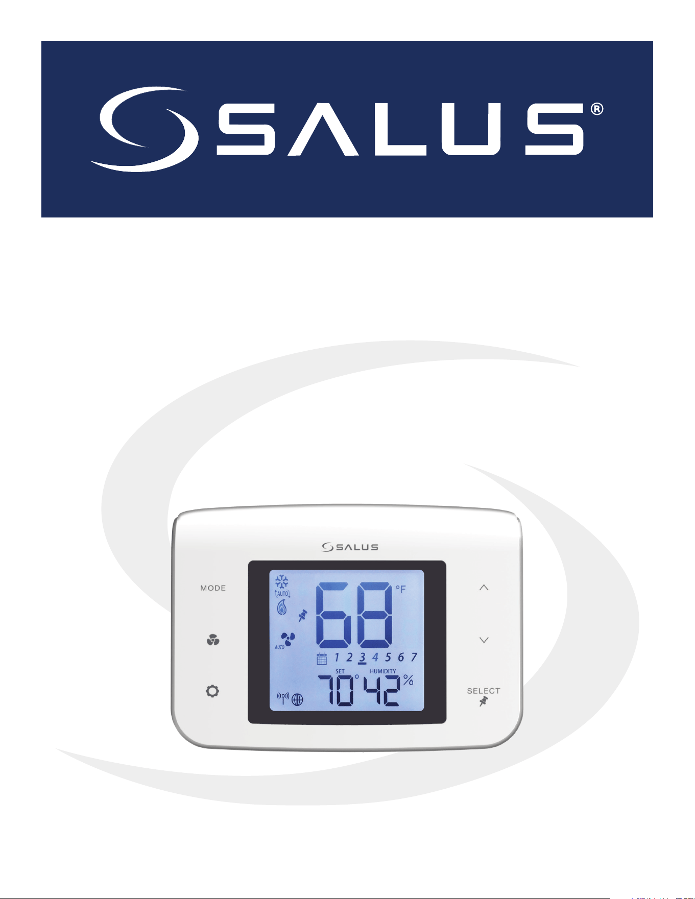
ST100ZB Line Power Fan Coil Thermostat
&
ST101ZB Low Voltage Fan Coil Thermostat
Installation & Operation Manual
As of August 16, 2019

Table of Contents
Introduction
System Overview .....................................................................................................3
Product Safety Information............................................................................................4
1.0 ST100ZB Line Power Fan Coil Thermostat
1.1 - Included Parts – ST100ZB Line Power Thermostat .................................................................5
1.2 - Tools (Required/Optional) ........................................................................................5
1.3 - Existing Wired Thermostat Removal...............................................................................6
1.4 - ST100ZB Line Power Fan Coil Thermostat Installation ..............................................................7
2.0 ST101ZB Low Voltage Fan Coil Thermostat
2.1 - Included Parts – ST101ZB Low Voltage Thermostat .............................................................. 10
2.2 - Tools (Required/Optional) ...................................................................................... 10
2.3 - Existing Wired Thermostat Removal............................................................................. 11
2.4 - ST101ZB Low Voltage Fan Coil Thermostat installation........................................................... 12
3.0 SS909ZB Optional Temperature Sensor
3.1 - Included Parts – SS909ZB Remote Temperature Sensor .......................................................... 14
3.2 - Tools (Required/Optional) ...................................................................................... 14
3.3 - SS909ZB Temperature Sensor Installation ....................................................................... 14
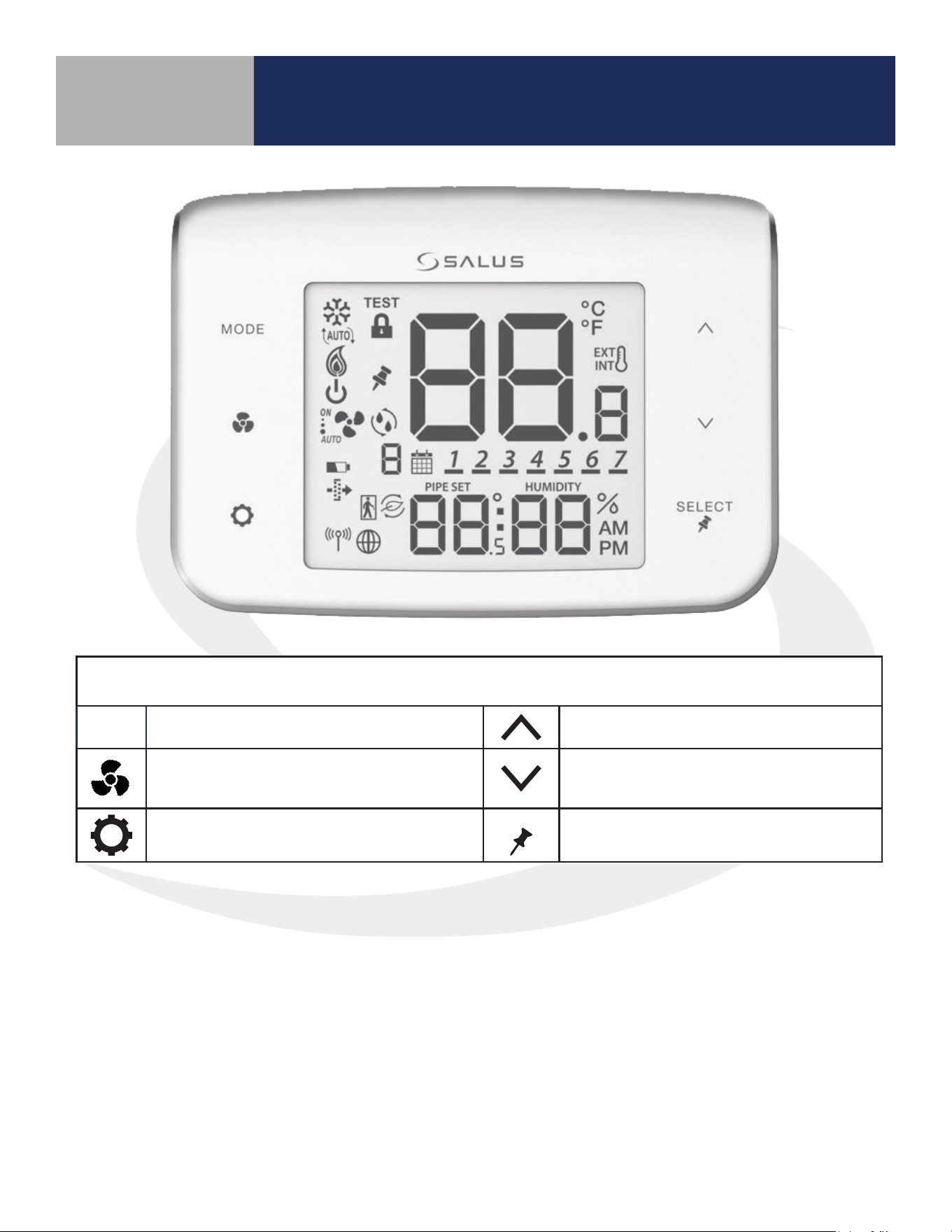
4.0 Fan Coil Thermostat Display & Keypad
4.1 - Keypad Functions . . . . . . . . . . . . . . . . . . . . . . . . . . . . . . . . . . . . . . . . . . . . . . . . . . . . . . . . . . . . . . . . . . . . . . . . . . . . . . . . . . . . . . . . . . . . . . 16
4.2 - Display Icons................................................................................................... 17
5.0 Joining & Pairing
5.1 - ST100ZB/ST101ZB Fan Coil Thermostat – Preparation for Joining the Network” ................................... 18
5.2 - Joining the SG888ZB Gateway Network ......................................................................... 18
5.3 - Optional SS909ZB Temperature Sensor Pairing .................................................................. 20
6.0 Thermostat Configuration
6.1 - Settings........................................................................................................ 24
6.2 - Special Functions .............................................................................................. 27
7.0 Operation
7.1 - ST100ZB/ST101ZB Fan Coil Thermostat – Preparation for Joining the Network” ................................... 29
7.2 - Joining the SG888ZB Gateway Network ......................................................................... 30
7.3 - Optional SS909ZB Temperature Sensor Pairing .................................................................. 30
7.4 - Heating/Cooling Modes ........................................................................................ 30
7.5 - Fan Modes ..................................................................................................... 31
7.6 - Accessory Function............................................................................................. 32
7.7 - AWAY Mode.................................................................................................... 33
8.0 Troubleshooting
8.0 - Troubleshooting ............................................................................................... 34
9.0 Installer Notes
9.0 - Installer Notes.................................................................................................. 35
Appendix A - Parameter List .........................................................................36
3
Introduction
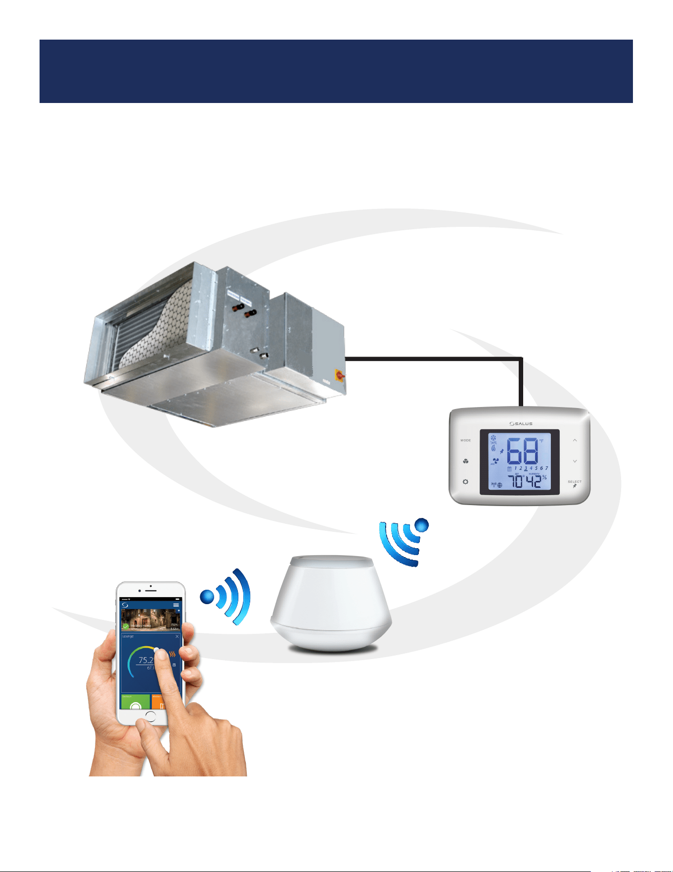
Fan Coil Thermostat System Overview
The SALUS fan coil thermostats provide remote control of fan coil units via the SALUS Smart
Home application for smart devices and PCs. Detailed instructions for the SALUS Smart Home
application are available in the SG888ZB Pairing Guide.
SG888ZB
Gateway
Fan Coil Unit
ST100ZB Fan Coil Thermostat
or
ST101ZB Fan Coil Thermostat
4
Introduction
Product Safety Information
Please read these instructions carefully BEFORE INSTALLING AND USING the Fan Coil
Thermostat. DO NOT supply line voltage (120 or 240 VAC) to a ST101ZB Low Voltage Fan Coil
Thermostat.
• DO NOT cover any of the vents on the thermostat
• DO NOT place the unit in a bathroom or area of excessive moisture
• DO NOT allow the unit to get wet. This device serves as a temperature control system only in
dry, closed living and office spaces.
• DO NOT use solvents or aggressive cleaning agents. A dry, soft cloth is recommended for
cleaning.
The manufacturer does not accept responsibility for any damage caused by not following these
instructions.
Codes & Regulations: Installation and setup of this product must be performed in strict
compliance with national, state/province, and local codes. Additional code requirements
for line voltage-powered devices may apply to the ST100ZB Line Power Fan Coil
Thermostat. An authorized, qualied installer may be required.
Intended Use: SALUS ST100ZB/ST101ZB Fan Coil Thermostats are intended for interior
room temperature control in conjunction with fan coil heating systems only. Other uses
are not recommended or supported.
Installer or Contractor: Record parameters at startup and any subsequent parameter
changes in the installer notes section of this manual.
5
Section 1.0
ST100ZB Line Power Fan Coil Thermostat
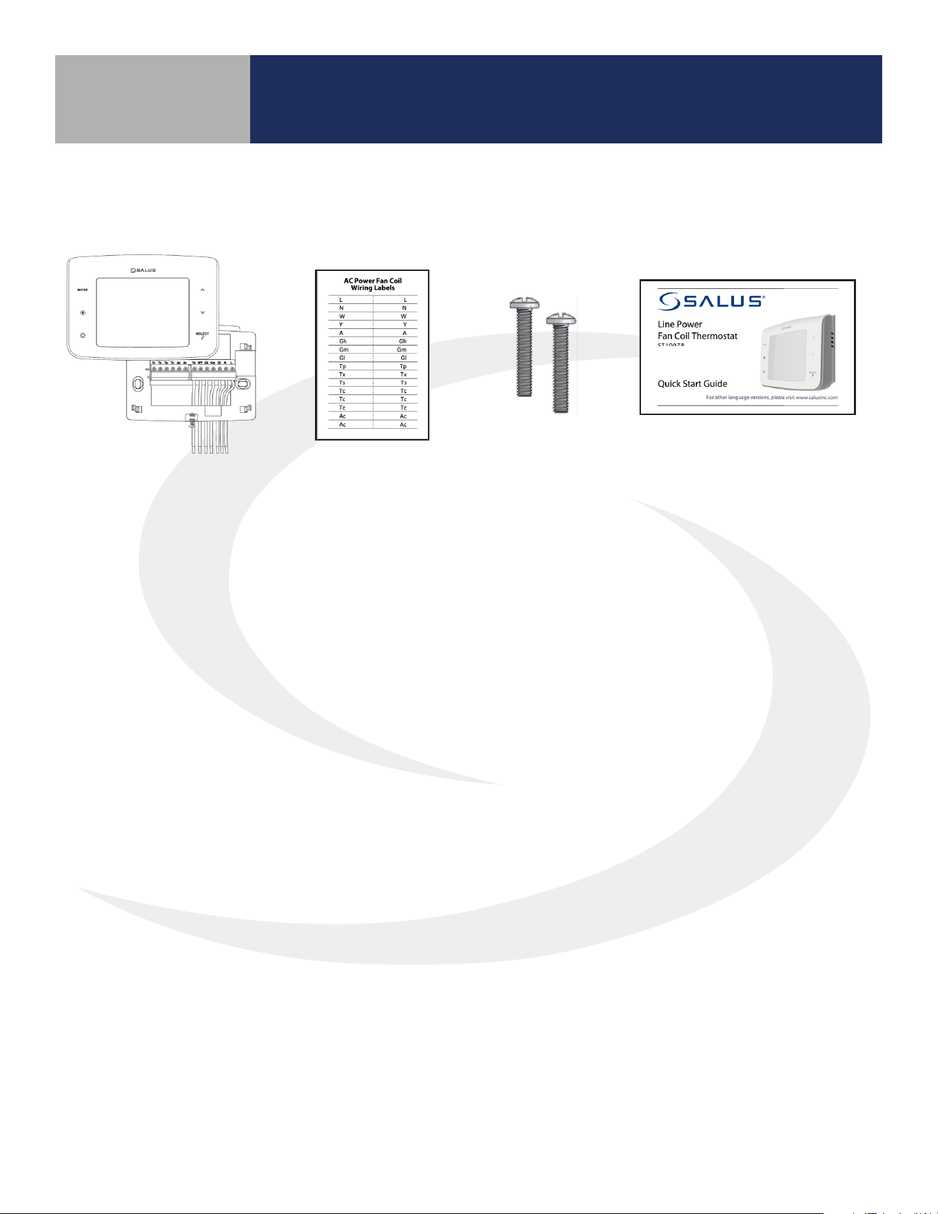
Be sure that all parts listed are included and available before starting installation.
1.1 Included Parts – ST100ZB Line Power Thermostat
1.2 Tools – Required/Optional
Required Tools:
• #1 Phillips or athead screwdriver
Optional Tools:
• Smartphone or digital camera for wiring reference photos
• Small screwdriver for removing wiring from old thermostat terminals
Thermostat with
Wiring Mount
Wiring Labels
Mounting
Screws
Installation/ Quick Start Guide
(English & French)

6
ST100ZB Line Power Fan Coil Thermostat
Step 1. If replacing an existing wired thermostat, review and record the wiring conguration of the
existing thermostat:
• Remove existing thermostat from the wall to expose the wiring terminals
• Take a photograph or note the wire colors and connections (see wiring reference table below)
• Attach wire labels to each of the wires
Section 1.0
Before beginning the installation procedure,
turn o power to the fan coil system.
1.3 Remove Existing Wired Thermostat
Terminal Wire Color
Function
4 Pipe System 2 Pipe System
L Black 120/240 VAC Line Power 120/240 VAC Line Power
N White 120/240 VAC Neutral 120/240 VAC Neutral
Gl Red Fan – Low Speed Fan – Low Speed
Gm Blue Fan – Medium Speed Fan – Medium Speed
Gh Brown Fan – High Speed Fan – High Speed
WY Orange Heating Valve Actuator Heat/Cool Valve Actuator
YA Yellow Cooling Valve Actuator Auxiliary Heat
Ac Accessory Contact Accessory Contact
Ac Accessory Contact Accessory Contact
Tp Supply Pipe Temp. Sensor Supply Pipe Temp. Sensor
Tx External Temp Sensor External Temp Sensor
Ts Temperature Setback Temperature Setback
Tc Tp/Tx/Ts Common Tp/Tx/Ts Common
Step 2. Label each wire when disconnecting them from the thermostat terminals and remove the
thermostat mounting plate (if necessary).
Paint the mounting surface, if desired, before mounting the thermostat back plate to ensure
complete wall coverage.
HVAC
THIS DOCUMENT CONTAINS
INFORMATION PROPRIETARY
TO AZ ENGINEERING.
DISCLOSURE OF ANY
INFORMATION CONVEYED OR
IMPLIED BY THIS DOCUMENT
WITHOUT EXPRESS WRITTEN
CONSENT BY AZ
ENGINEERING IS FORBIDDEN.
APPROVED BY
DATE
AZ ENGINEERING LLC
DRAWING TITLE
SCALE: DRAWING NO: REVISION:
SHEET 1 OF 1
DATE:DRAWN BY:
CN:
SUBTITLE
CLI-YYMMDD-01
00
SCALE
-- SCEARCE YYYY-MM-DD
REVISION
BY: DATE:
7
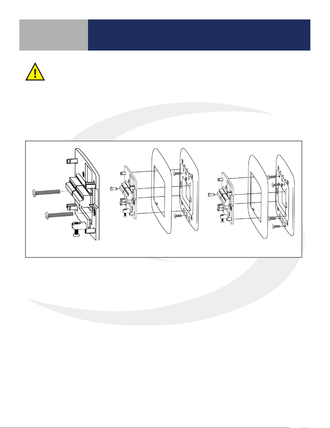
ST100ZB Line Power Fan Coil Thermostat
Horizontal 2” x 4” Box
Vertical 2” x 4” Junction Box
(wall plate sold separately)
4” x 4” Junction Box
(wall plate sold separately)
Section 1.0
Step 1. Install the Wiring Mount in the desired location using the junction box screws provided, making
sure the wires go through the center opening. An optional wall plate (sold separately) is available for
mounting to other junction box congurations (see below).
1.4 ST100ZB Fan Coil Thermostat Installation
A split junction box may be required in some jurisdictions to separate line voltage supply
wires from low voltage sensor leads.
8
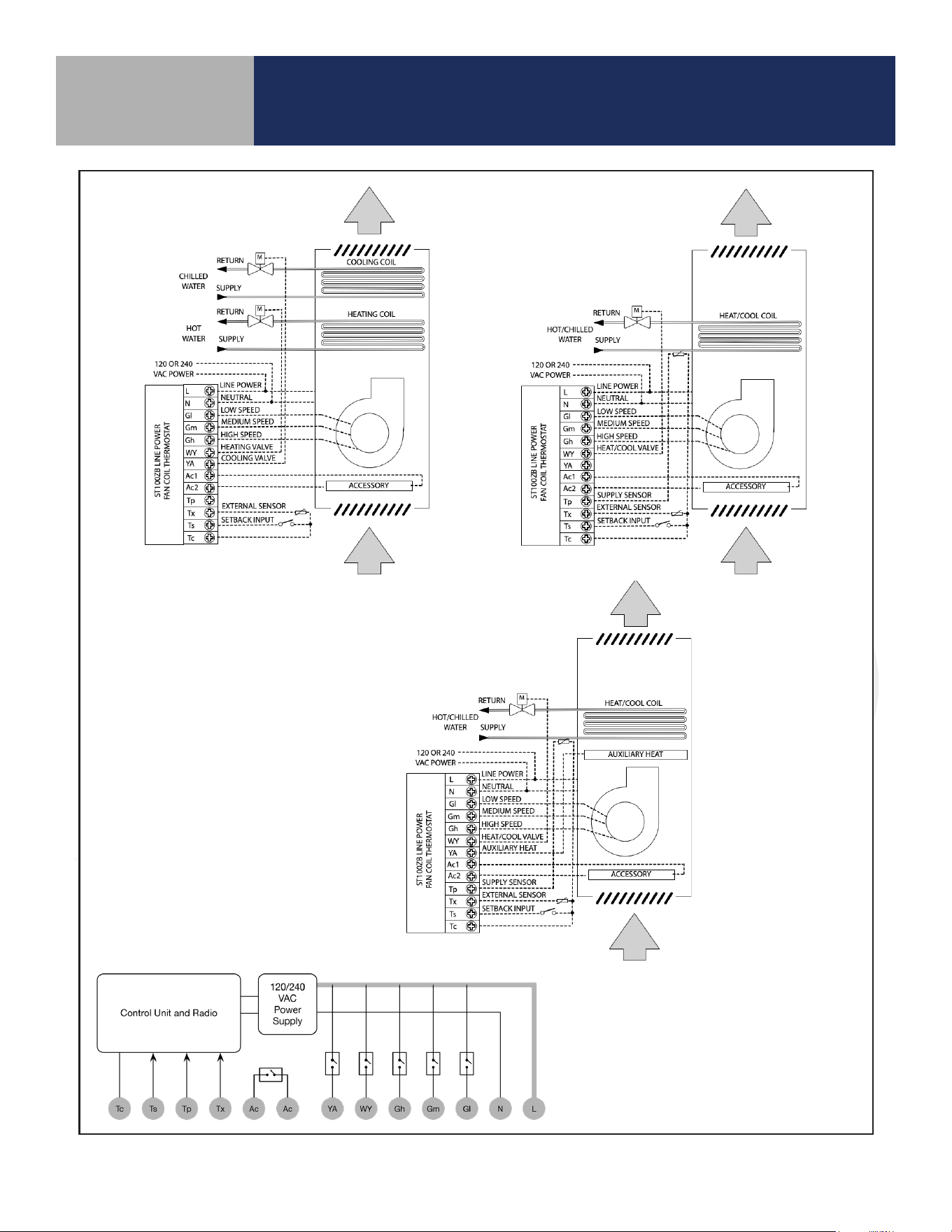
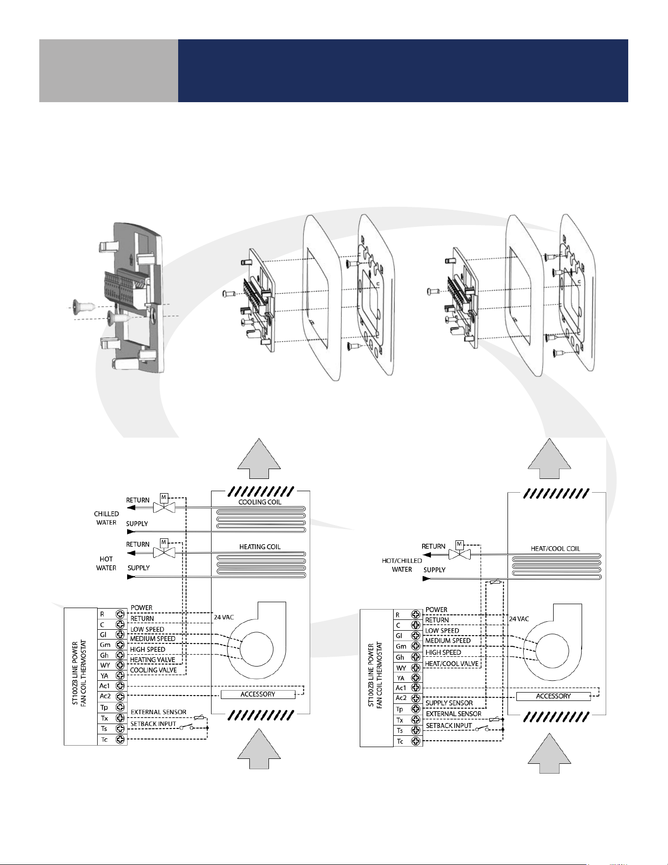
ST100ZB Line Power Fan Coil Thermostat
Section 1.0
Internal Block Diagram
ST100ZB
4-Pipe Application
ST100ZB
2-Pipe Application
ST100ZB
2-Pipe Auxiliary
Heat Application
9
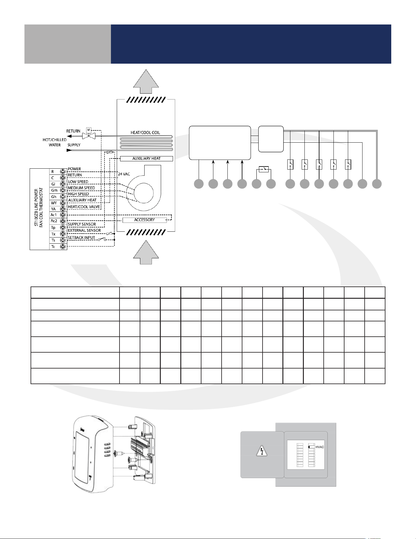
ST100ZB Fan Coil Thermostat Installation
Section 1.0
Step 3. Attach Thermostat to the wiring mount by aligning the connector pins.
Configuration L N Gl Gm Gh WY YA Ac Ac Tp Tx Ts Tc*
2-Pipe Heat Only
W o o o o o o
2-Pipe Cool Only
Y o o o o o o
2-Pipe Heat/Cool
Manual Changeover
W/Y o o o o o o
2-Pipe Heat/Cool
Seasonal Changeover
W/Y o o
o o
2-Pipe Heat/Cool
w/Auxiliary Heat
W/Y A o o
o o
4-Pipe Heat/Cool w/Manual
or Auto Changeover
W Y o o o o o
=Required / o=Optional / W=Heat Valve Actuator / Y=Cool Valve Actuator / A=Auxiliary Heat
* If using more than one (Tp/Tx/Ts) terminal, it may be necessary to splice Tc.
Make sure the connector pins are not bent and that the Thermostat is fully seated on the
wiring mount.
Step 2. Connect wiring to the ST100ZB Back Plate – Use the following chart to identify the
desired conguration.
Remove any unused, pre-wired leads or add wire nut cap to isolate line voltage.
10
ST101ZB Low Voltage Fan Coil Thermostat
Section 2.0
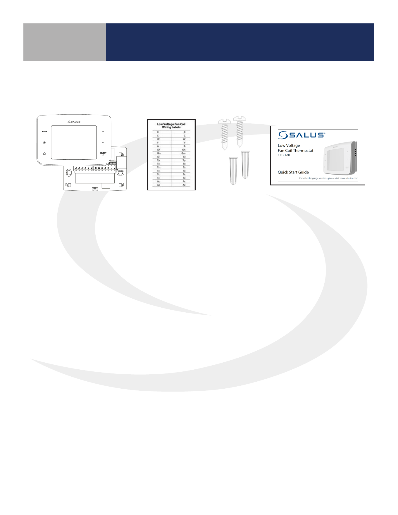
2.1 Included Parts – ST101ZB Low Voltage Thermostat
Required Tools:
• #1 Phillips or athead screwdriver
• Drill with 3/16” bit if wall anchors are required
Optional Tools:
• Smartphone or digital camera to take photos of wiring for later reference
• Screwdriver to disconnect wires from existing thermostat
• Pencil for capturing wires
Thermostat with
Wiring Mount
Wiring Labels
Screws and
Anchors
Installation/ Quick Start
Guide (English & French)
2.2 Tools – Required/Optional
Be sure that all parts listed are included and available before starting installation.
11
ST101ZB Low Voltage Fan Coil Thermostat
Section 2.0
Before beginning the installation procedure,
turn power o to the fan coil system.
2.3 Remove Existing Wired Thermostat
Terminal Wire Color
Function
4 Pipe System 2 Pipe System
R Black 24 VAC Input 24 VAC Line Power
C White 24 VAC Common 24 VAC Common
Gl Red Fan – Low Speed Fan – Low Speed
Gm Blue Fan – Medium Speed Fan – Medium Speed
Gh Brown Fan – High Speed Fan – High Speed
WY Orange Heating Valve Actuator Heat/Cool Valve Actuator
YA Yellow Cooling Valve Actuator Auxiliary Heat
Ac Accessory Contact Accessory Contact
Ac Accessory Contact Accessory Contact
Tp Supply Pipe Temp. Sensor Supply Pipe Temp. Sensor
Tx External Temp Sensor External Temp Sensor
Ts Temperature Setback Temperature Setback
Tc Tp/Tx/Ts Common Tp/Tx/Ts Common
C
Y
R
THIS DOCUMENT CONTAINS
INFORMATION PROPRIETARY
TO AZ ENGINEERING.
DISCLOSURE OF ANY
INFORMATION CONVEYED OR
IMPLIED BY THIS DOCUMENT
WITHOUT EXPRESS WRITTEN
CONSENT BY AZ
ENGINEERING IS FORBIDDEN.
APPROVED BY
DATE
AZ ENGINEERING LLC
Wired Fan Coil Thermostat Replacement
SCALE: DRAWING NO: REVISION:
SHEET 1 OF 1
DATE:DRAWN BY:
CN:
Pencil Wrap
SCI-190103-01
01
NONE
-- SCEARCE 2019-01-03
REVISION
BY:
01
DAS
DATE:
08/16/2019
ADDED DRAWING TITLE, WIRE TAG "R" (was) "RC", WIRE TAG "Y" (was) "Y1".
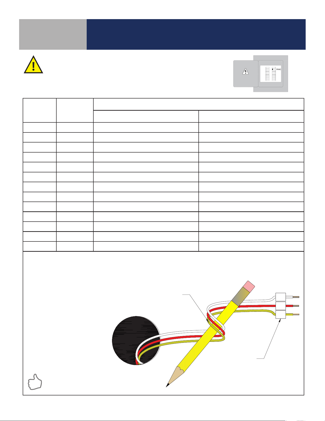
LABEL WIRES TO CORRESPOND
WITH THERMOSTAT TERMINALS
WRAP WIRES AROUND A PENCIL
OR SIMILAR OBJECT TO PREVENT
THEM FROM FALLING INTO THE
WALL VOID
Step 1. Remove existing thermostat from the wall to expose the wiring terminals.
Step 2. Photograph the wiring connections for future reference
Step 3. Label each wire according to its terminal attachment
Step 4. Carefully remove the wires and any existing mounting plate
Paint the mounting surface, if desired,
before mounting the thermostat back
plate to ensure complete wall coverage.
12
ST101ZB Low Voltage Fan Coil Thermostat
Section 2.0
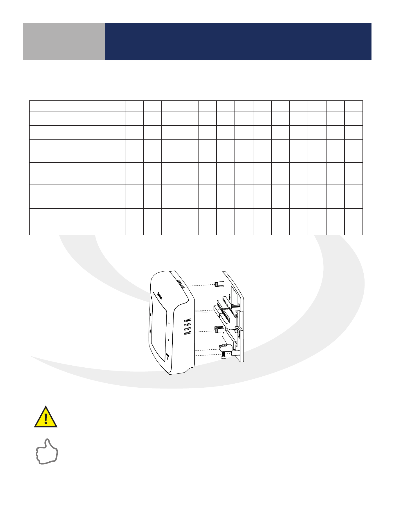
Step 1. Use the included wall screws and/or anchors to attach the wiring mount to the
wall, making sure the wires go through the center opening. If alternate mounting holes are
required, use a wall plate (sold separately.)
No box or horizontal
single gang box
Vertical single gang box
(wall plate sold separately)
2 gang (4' square) box
(wall plate sold separately)
2.4 ST101ZB Low Voltage Fan Coil Thermostat Installation
ST101ZB 4-Pipe Application ST101ZB 2-Pipe Application
13
ST101ZB Low Voltage Fan Coil Thermostat
Section 2.0
Step 2. Attach the wires to the matching terminals based on the fan coil conguration as follows:
Step 3. Attach thermostat to the
wiring mount.
Step 4. Turn on power to the fan coil system
and thermostat.
Configuration R C Gl Gm Gh WY YA Ac Ac Tp Tx Ts Tc*
2-pipe Heat Only
W O O O O O O
2-pipe Cool Only
Y O O O O O O
2-pipe Heat or Cool -
Manual Changeover
W/Y O O O O O O
2-Pipe Heat or Cool –
Seasonal Changeover
W/Y O O
O O
2-Pipe Heat or Cool w/
Auxiliary Heat
W/Y A O O
O O
4-Pipe Heat/Cool Manual
or Auto Changeover
W Y O O O O O
=Required / o=Optional / W=Heat Valve Actuator / Y=Cool Valve Actuator / A=Auxiliary Heat
* If using more than one (Tp/Tx/Ts) terminal, it may be necessary to splice Tc.
Internal Block Diagram
ST101ZB 2-Pipe Auxiliary
Heat Application
RCAc YA WYAc GlGh GmTxTc TpTs
Control Unit and Radio
24VAC
Power
Supply
14
SS909ZB Optional Temperature Sensor
Section 3.0
3.2 Tools – Required
• #1 Phillips athead screwdriver
3.3 SS909ZB Temperature Sensor Installation
The SS909ZB Temperature Sensor should be located at a point where the temperature
is to be used to control the fan coil thermostat. This temperature sensor can be
permanently mounted on a wall or on the desk stand provided. If mounted on the desk
stand, the SS909ZB can be moved to dierent locations to provide maximum comfort.
For instructions on connecting the temperature sensor to a Fan Coil Thermostat, refer to
Section 5.0 – Joining & Pairing.
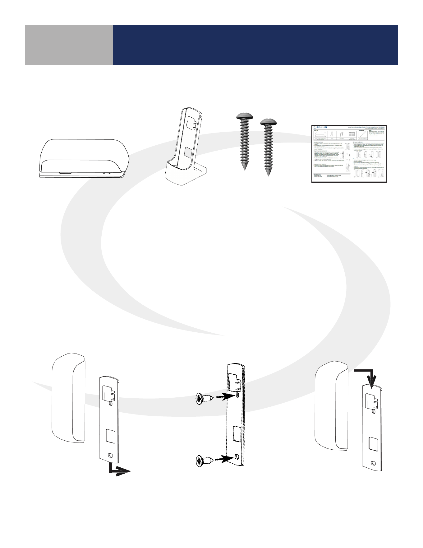
3.1 SS909ZB Temperature Sensor
Step 3.
Slip the SS909ZB
Temperature Sensor
onto the Wall Mount.
Step 1.
Remove the Wall Plate from
the back of the SS909ZB
Temperature Sensor.
Step 2.
Attach the Wall Mount in the
desired location using the
screws and anchors provided.
Be sure that all parts listed are included and available before starting installation.
Installation
Guide
Temperature Sensor with
Battery and Wall Plate
Stand
Mounting
Screws
15
SS909ZB Optional Temperature Sensor
Section 3.0
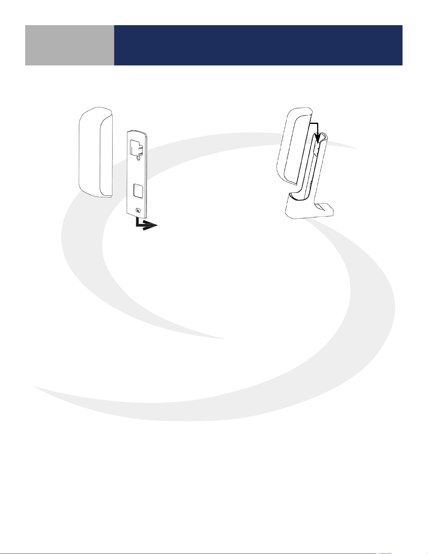
3.3.2 Desktop Mounting – SS909ZB Temperature Sensor
Step 1.
Remove the Wall Plate from the back of
the SS909ZB Temperature Sensor.
Step 2.
Slip the SS909ZB Temperature Sensor
onto the Desk Mount.
16
4.1 Keypad Functions
MODE
Heat, Cool, Auto, Off selection Increase Value
Fan On/Auto, Low Speed, Medium
Speed, or High Speed
Decrease Value
Enter/Exit Settings mode
SELECT
Confirm/Change Display Mode/Acti-
vate Permanent Hold
Fan Coil Thermostat Display & Keypad
Section 4.0
17
Fan Coil Thermostat Display & Keypad
Section 4.0
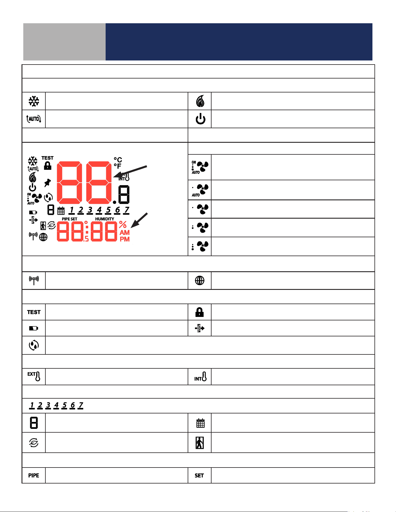
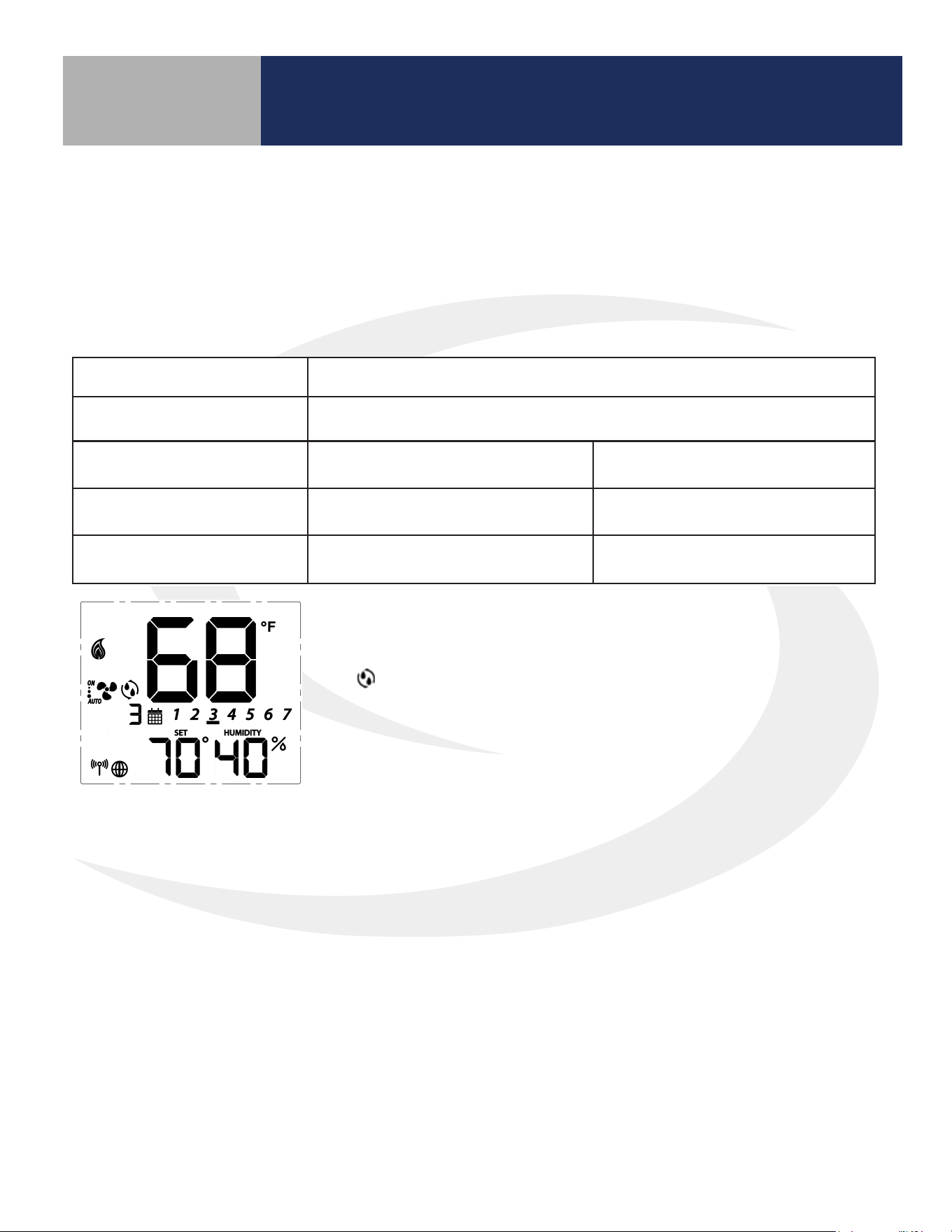
4.2 Display Icons
Heat/Cool/Off Modes
Cooling (Animated when cooling is on)
Heating (Animated when heat is on)
Auto Heat/Cool Changeover
Off (Will not respond to Heat/Cool demand)
Fixed Segment Display Fan Modes
Fixed Segment Display
ON – Indicates Constant Fan Enabled
3 Dots – High Speed
AUTO – Indicates Fan is in Automatic Speed Mode
AUTO – Automatic Speed Mode; Constant Fan
Disabled; Low Speed
Fixed Low Fan Speed – Constant Fan Disabled
Fixed Medium Fan Speed – Constant Fan Disabled
Fixed High Fan Speed – Constant Fan Disabled
Wireless/Internet Indications
Device connected to local network Device connected to SALUS Smart Home Service
Test/Key Lock/Battery/Filter
Test Mode (Special Code 22) Keys Locked Mode
Battery Low (Not Used) Change Filter (Timer expired)
Accessory Output On (Humidifier, Dehumidifier, ERV or HRV)
Internal/External Temperature Sensor
External Sensor Indication (wired or wireless)
Internal Sensor Indication (Only visible in TEST Mode)
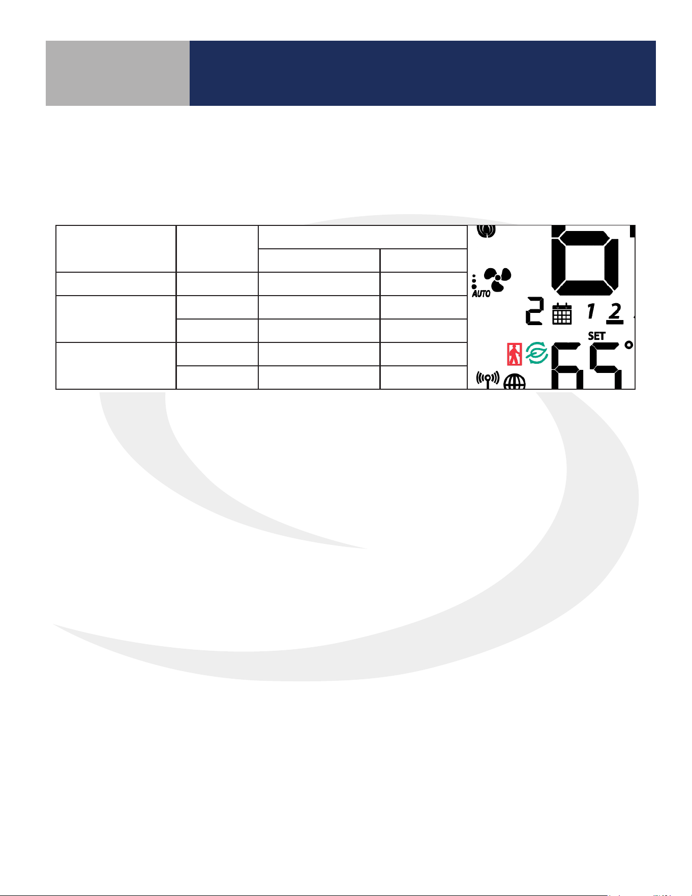
Schedule Indications
Day of the week (Mon = 1, Tue = 2, Wed = 3, Thu = 4, Fri = 5, Sat = 6, Sun = 7)
Schedule Interval (1-6) - Specifies time interval
of scheduled temperature changes
Schedule Indicator – When shown, the Thermostat is
following a schedule
Setback Indicator – Setback input is activated
AWAY State Indicator – Displayed when the Fan Coil
Thermostat is set to AWAY, using setback temperatures
Multifunction Temperature Indication
Pipe temperature reading shown Setpoint temperature reading shown
Room
Temperature
Display
Multifunction
Display -
Setpoint/
Humidity/
Time
18
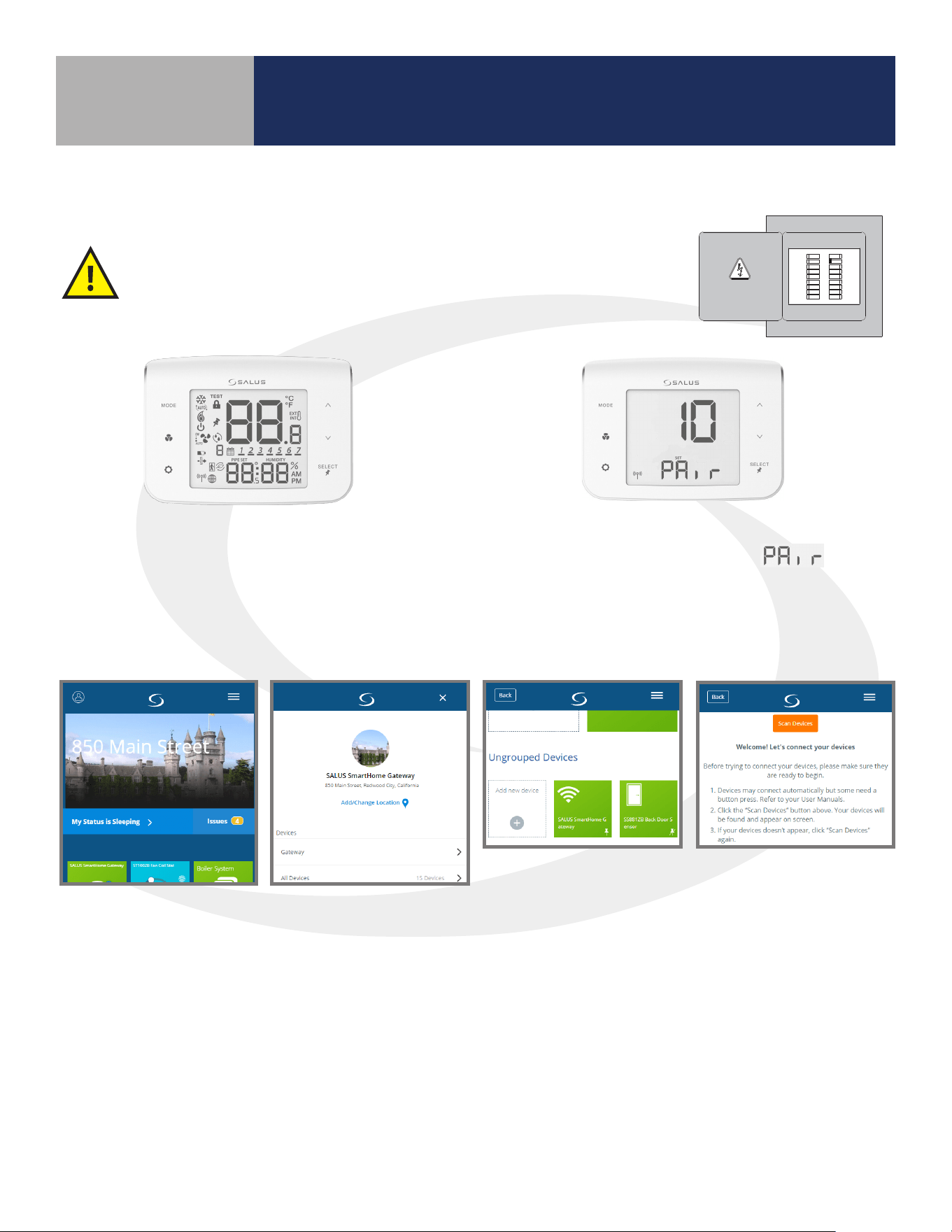
Device Joining & Pairing
Section 5.0
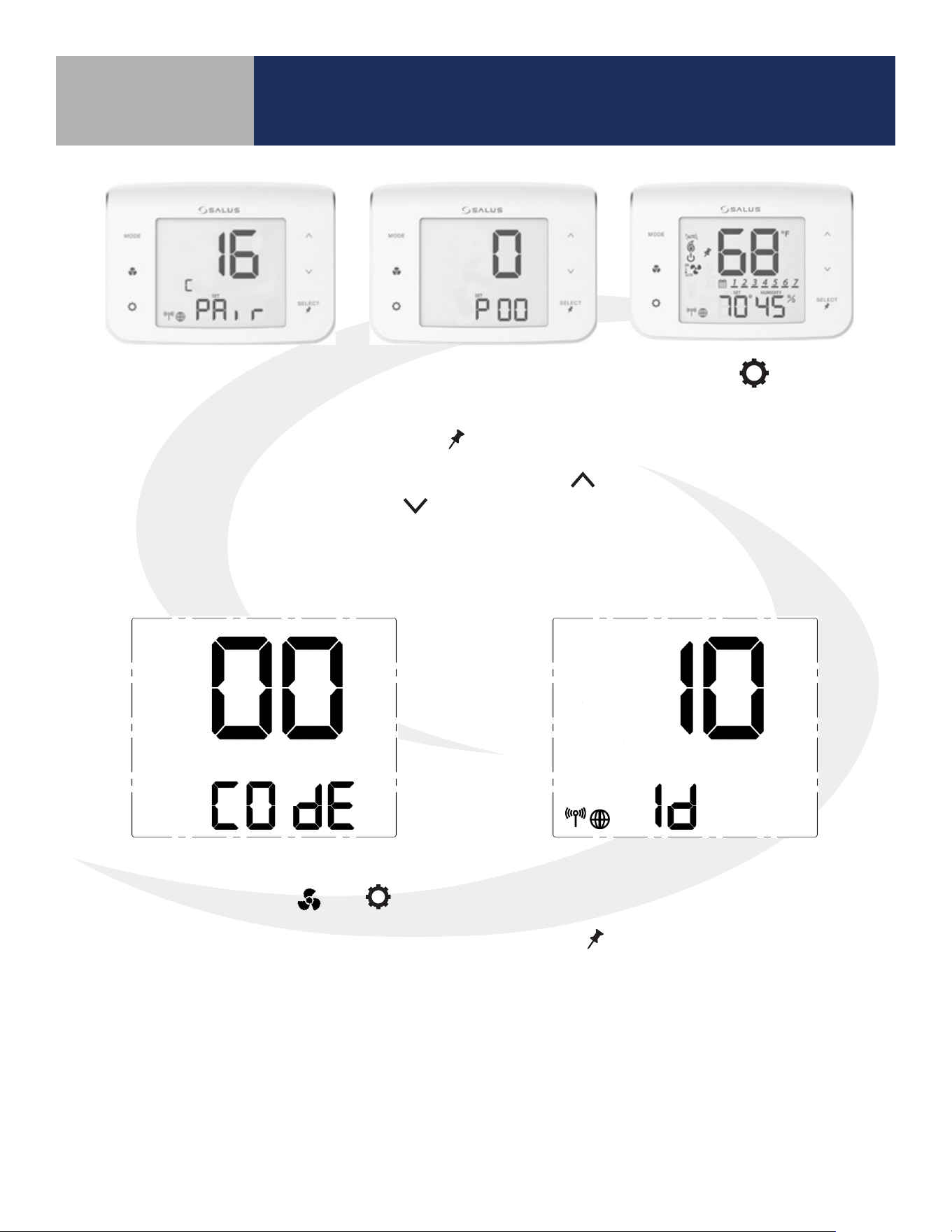
When the Fan Coil Thermostat is rst powered, all
segments will be briey displayed. The display will then
show the rmware version.
After installing the Fan Coil Thermostat and any optional SS909ZB
Temperature Sensors, turn on electrical power to the fan coil system
and Fan Coil Thermostat.
5.1 Fan Coil Thermostat – Preparation for Joining the Network
If the Fan Coil Thermostat is not connected to a
network, the device will display and a
10 minute countdown timer will start.
HVAC
THIS DOCUMENT CONTAINS
INFORMATION PROPRIETARY
TO AZ ENGINEERING.
DISCLOSURE OF ANY
INFORMATION CONVEYED OR
IMPLIED BY THIS DOCUMENT
WITHOUT EXPRESS WRITTEN
CONSENT BY AZ
ENGINEERING IS FORBIDDEN.
APPROVED BY
DATE
AZ ENGINEERING LLC
DRAWING TITLE
SCALE: DRAWING NO: REVISION:
SHEET 1 OF 1
DATE:DRAWN BY:
CN:
SUBTITLE
CLI-YYMMDD-01
00
SCALE
-- SCEARCE YYYY-MM-DD
REVISION
BY: DATE:
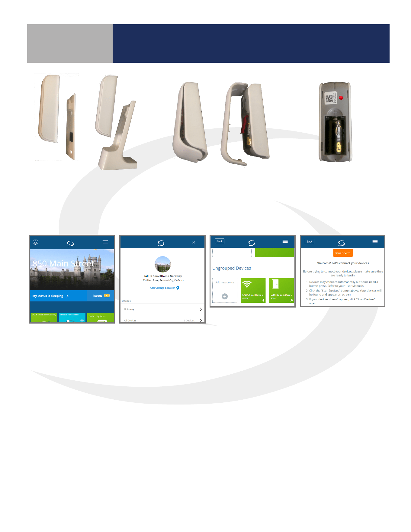
5.2 Joining the SG888ZB Gateway Network
Step 1.
Open the SALUS Smart Home application, select the drop-down menu from the upper right of the
screen and choose: All Devices Add New Device Scan Devices
19
Device Joining & Pairing
Section 5.0
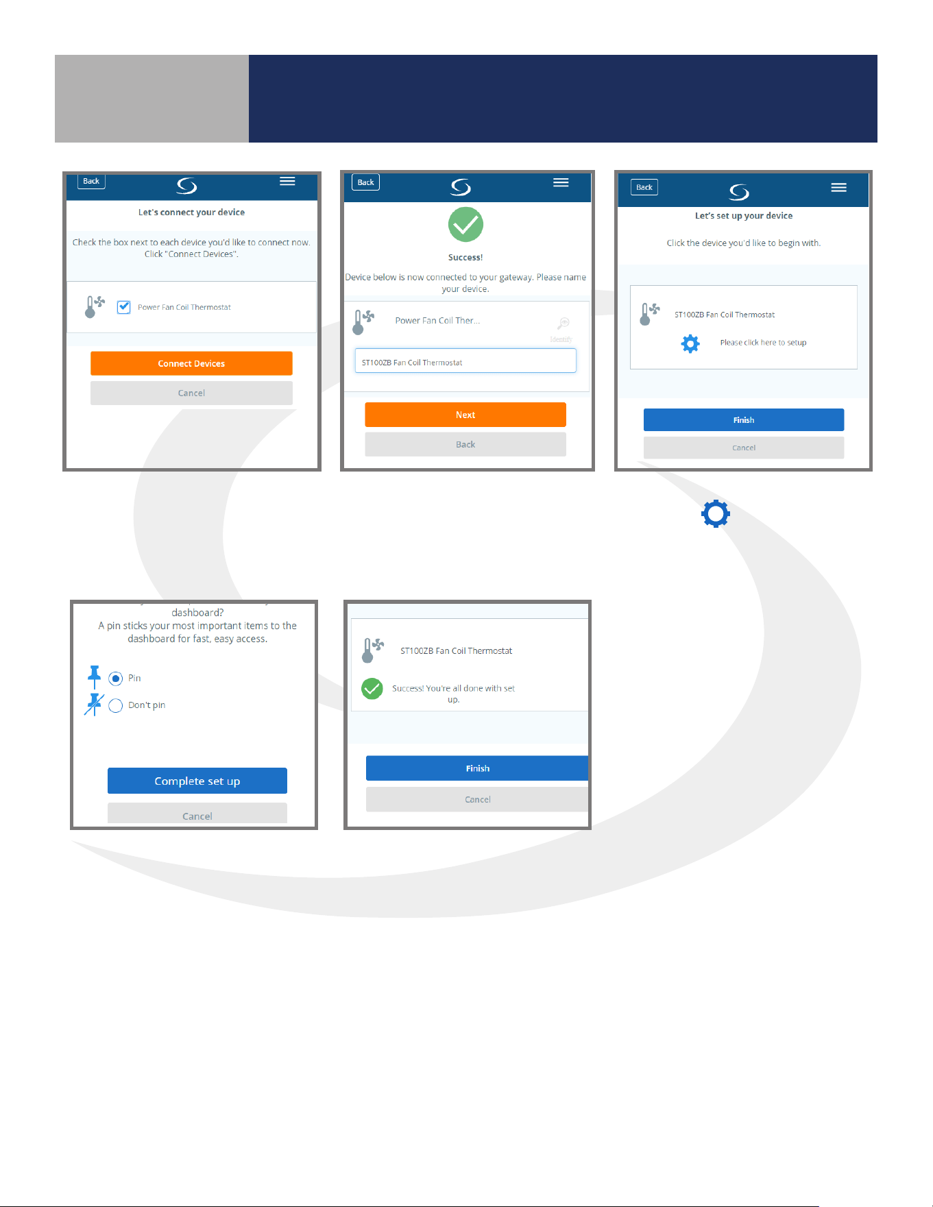
Step 2.
Check the box corresponding
to the appropriate Fan Coil
Thermostat and press “Connect
equipment.”
Step 4.
Press the icon to enter
‘setup’ mode
Step 3.
Enter a unique name for the
device and press “Next.”
Step 5.
Make desired changes to setup.
Scroll down and choose
“Complete set up”.
Step 6.
Choose "Finish"
20
Once the Fan Coil
Thermostat is successfully
paired with a gateway, the
device will briey display
the Zigbee channel.
Device Joining & Pairing
Section 5.0
Next, the Fan Coil Thermostat
enters Parameter Setup.
Use the
SELECT
key to scroll
through available parameters
(See Appendix A) and the
and to make changes.
Press the key to
enter the operation
screen.
5.3 Optional SS909ZB Temperature Sensor Pairing
Step 1.
Press and Hold the MODE, , and keys
simultaneously on the Fan Coil Thermostat
to display the screen above for entering
Special Function Codes.
Step 2.
Make sure the screen reads 00 COdE and
press
SELECT
to enter the Identify Mode.
A10-minute countdown timer begins.
21
Device Joining & Pairing
Section 5.0
Step 5.
When the battery tab
is removed, the red
LED will begin to ash.
Step 3.
Remove the SS909ZB Remote
Temperature Sensor from the Wall
Plate or Desk Stand.
Step 4.
Use a small screwdriver to
remove the face plate from the
Remote Temperature Sensor
and pull the battery tab.
Step 6.
Open the SALUS Smart Home application, select the drop-down menu from the upper right of the
screen and choose: All Devices Add New Device Scan Devices
22
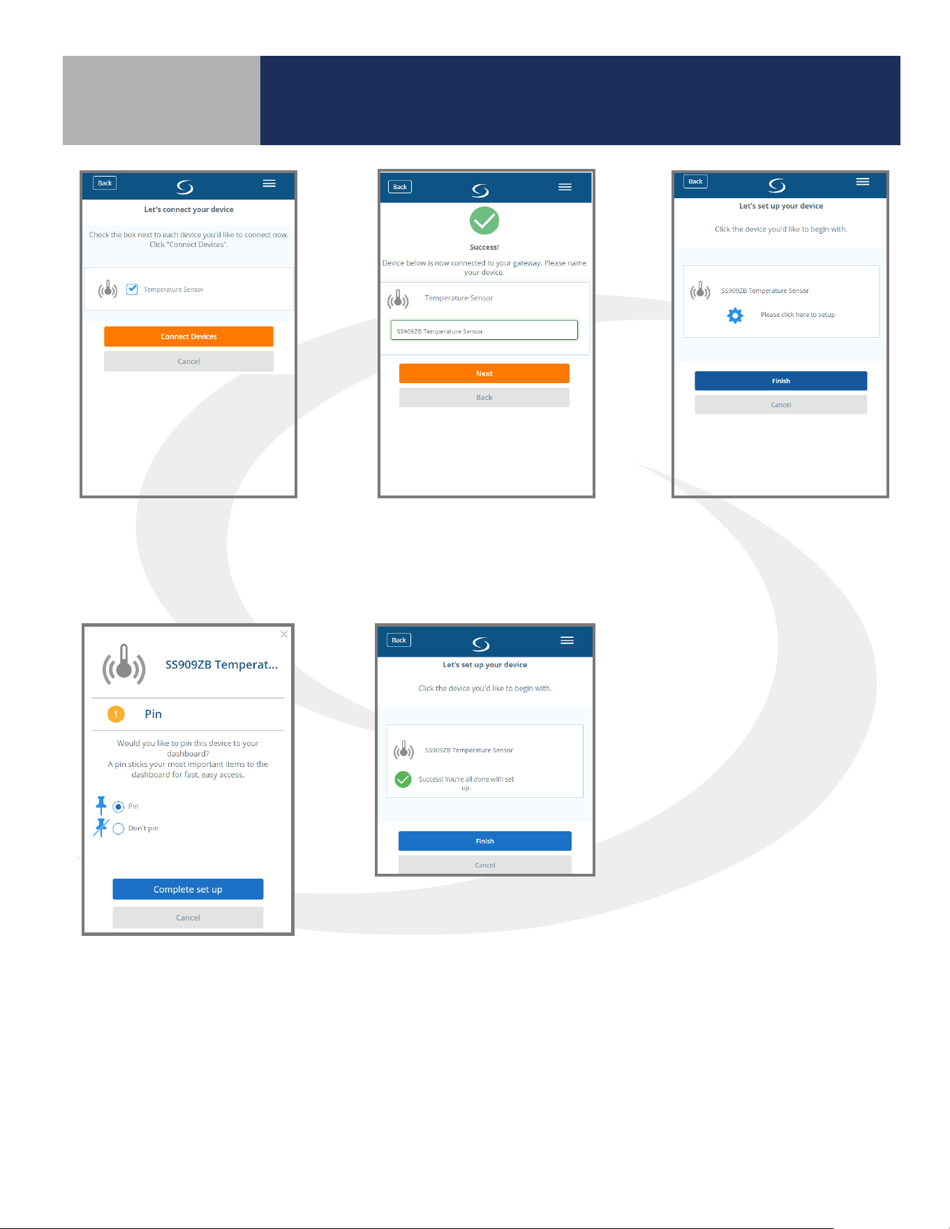
Step 9.
Press “Please click here to
setup”.
Step 7.
Check “Temperature
Sensor” device checkbox
and click “Connect Devices”
Step 8.
Enter a unique name for
the device and press “Next".
Device Joining & Pairing
Section 5.0
Step 10.
Choose Pin or Don’t Pin.
Press “Complete set up”.
Step 11.
Press “Finish” to complete
the setup.
The sensor will automatically initiate an operation to associate it with the Fan Coil Thermostat that is in
Identify Mode.
23
Device Joining & Pairing
Section 5.0
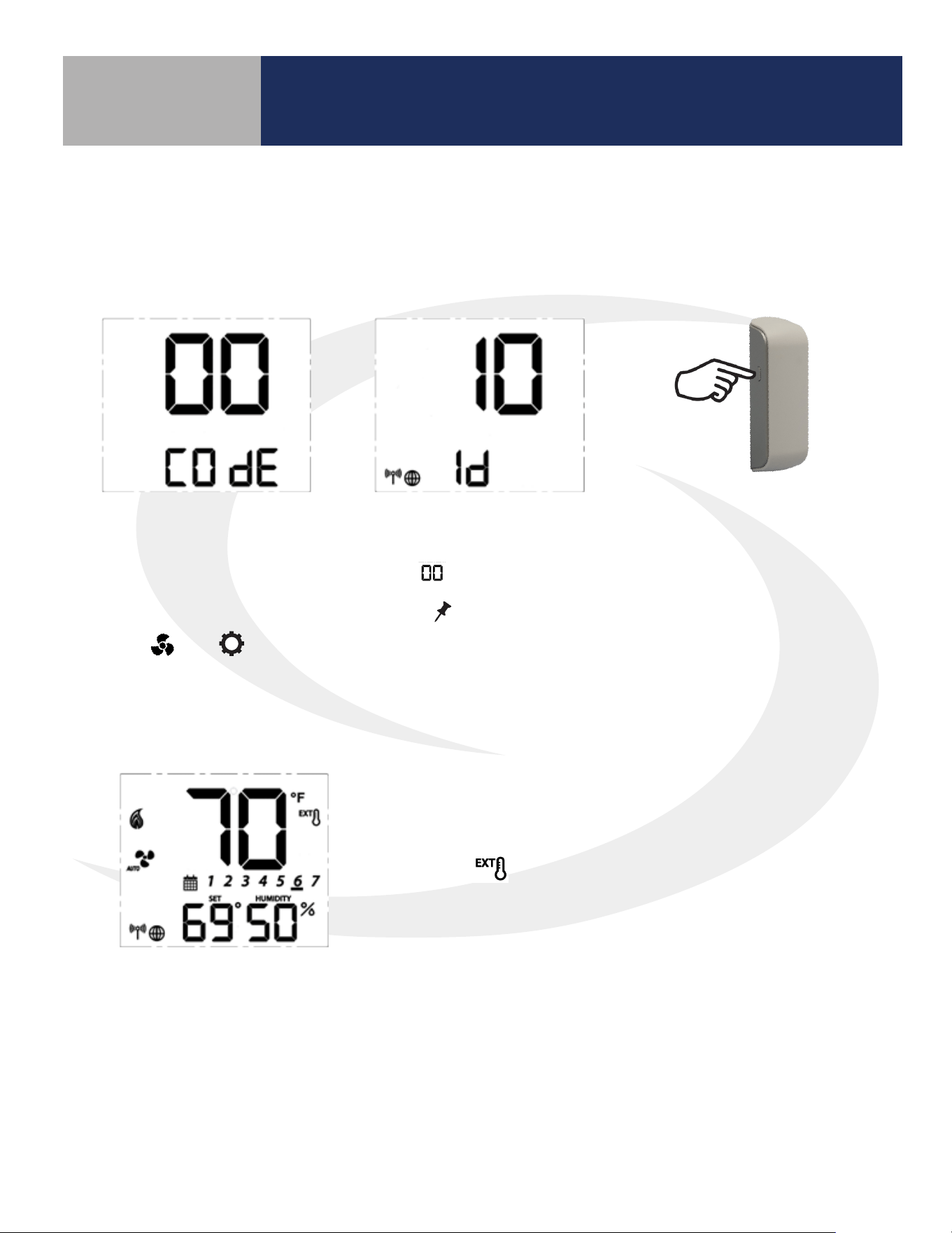
Step 11.
If the Fan Coil Thermostat is set to EXT, Parameter P12 is set to 1 (Zigbee remote sensor) and the
temperature display shows “- -“ instead of a temperature value, do the following to be sure the SS909ZB
Temperature Sensor is paired with the Fan Coil Thermostat.
Step 11a.
Make sure the Fan Coil
Thermostat is in Identify Mode
by pressing and holding the
MODE , , and keys on
the ST100ZB Thermostat to
enter Special Function Codes.
Step 11b.
When is displayed
press
SELECT
to enter the
Identify Mode on the Fan
Coil Thermostat.
Step 11c.
Press and hold the pairing
button on the SS909ZB
Temperature Sensor for
approximately 3 seconds
until the LED illuminates.
Immediately, release and
then press the pairing
button again.
When the LED goes out, the SS909ZB Sensor will be associated
with the Fan Coil Thermostat, the sensor temperature will be
displayed and the icon indicates an external thermostat is
connected.
24
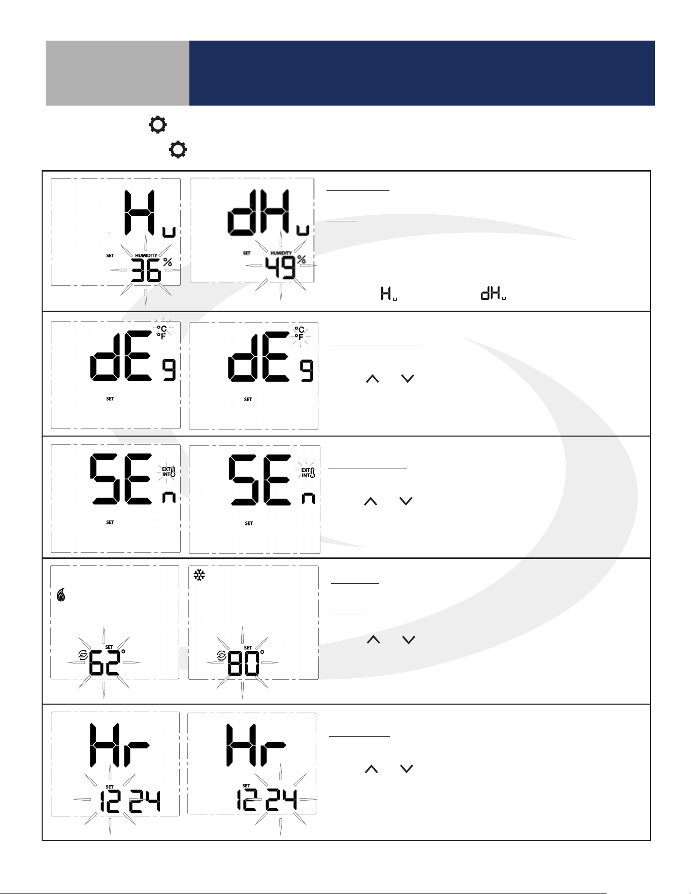
* Humidity: This setting allows users to adjust the relative
humidity setpoint.
Range: Humidifier – 20% to 50%
Dehumidifier – 40% to 80%
The ^ and v keys adjust the flashing relative humidity setpoint. Press
SELECT to choose the displayed value and move to the next setting.
* This setting is only available if the accessory parameter (P22) is set to
Humidifier ( ) or Dehumidifier ( ).
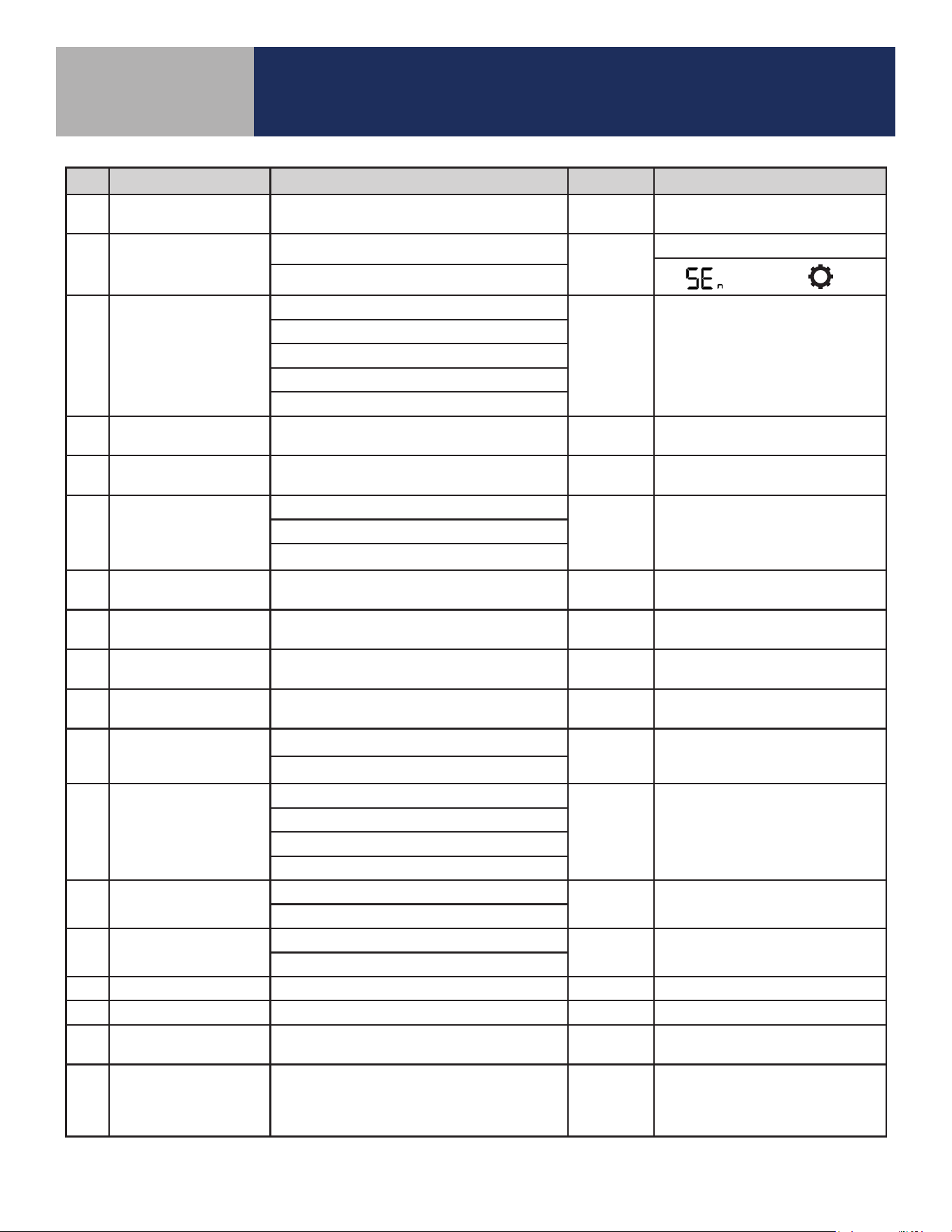
Temperature Units: Use this setting to choose between SI Metric and
US Customary temperature units.
Use the and keys to toggle between °C and °F. Press
SELECT to choose the flashing value and move to the next
setting.
Sensor Location: Use this setting to choose between internal (INT)
and external (EXT) sensor location.
Use the and keys to toggle between INT and EXT. Press SELECT
to choose the flashing value and move to the next setting (If INT is
chosen, INT will not be displayed on the home screen).
* Setback: Use this setting to choose a setback temperature for heat-
ing and/or cooling.
Range: Heat – 50-68°F (10-20°C)
Cooling – 73-90°F (23-32°C)
Use the and keys to change the setback temperature. Press
SELECT to choose the flashing value and move to the next setting.
* This setting is only available if the setback input parameter (P16) is
enabled.
Clock Format: This setting is used to change the clock format be-
tween 12 hour with am/pm and 24 hour.
Use the and keys to toggle between 12 and 24 hour clock.
Press SELECT to choose the value displayed and move on to the next
setting.
Configuration
Section 6.0
6.1 Settings Button Operation
Pressing the SETTINGS button will allow adjustment of user selectable settings.
25
Configuration
Section 6.0
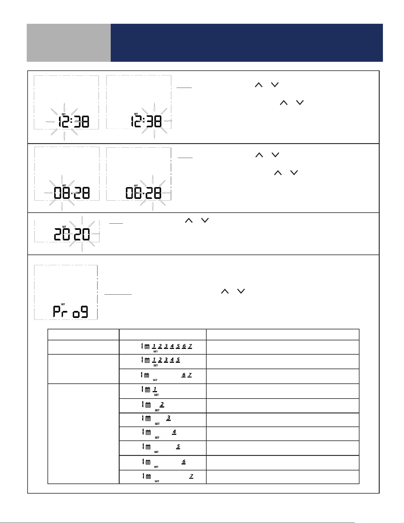
Time: To set the time, use the or keys to change the flashing hour
value, then press SELECT to choose the value displayed and select minutes.
With the minute value flashing, use the or keys to change the value.
Press SELECT to choose the value displayed and move to the next setting.
Note: This setting is available in standalone or local mode only.
Date: To set the date, use the or keys to change the flashing month
value, then press SELECT to choose the value displayed and select date.
With the date value flashing, use the or keys to change the value.
Press SELECT to choose the value displayed and move to the next setting.
Note: This setting is available in standalone or local mode only.
Year: To set the year, use the or keys to change the flashing year value.
Press SELECT to choose the value displayed and move to the next setting.
Note: This setting is available in standalone or local mode only.
Note: Schedule parameters are only available in standalone or local mode. If the Fan Coil Thermostat
is connected to the SALUS Smart Home application, the schedule must be programmed on your PC or
smart device.
Schedule: While Prog is displayed, press the or keys to change the day group to be edited.
See the following table that describes which days are programmed based on the display.
After selecting the day group, press SELECT to move to setting temperatures for each interval during
the day.
Program Mode Day Group Displayed Schedule Description
Weekly Every day of the week
5+2
Weekdays/Weekend
(Default)
Monday through Friday
Saturday and Sunday
Daily
Monday
Tuesday
Wednesday
Thursday
Friday
Saturday
Sunday
26
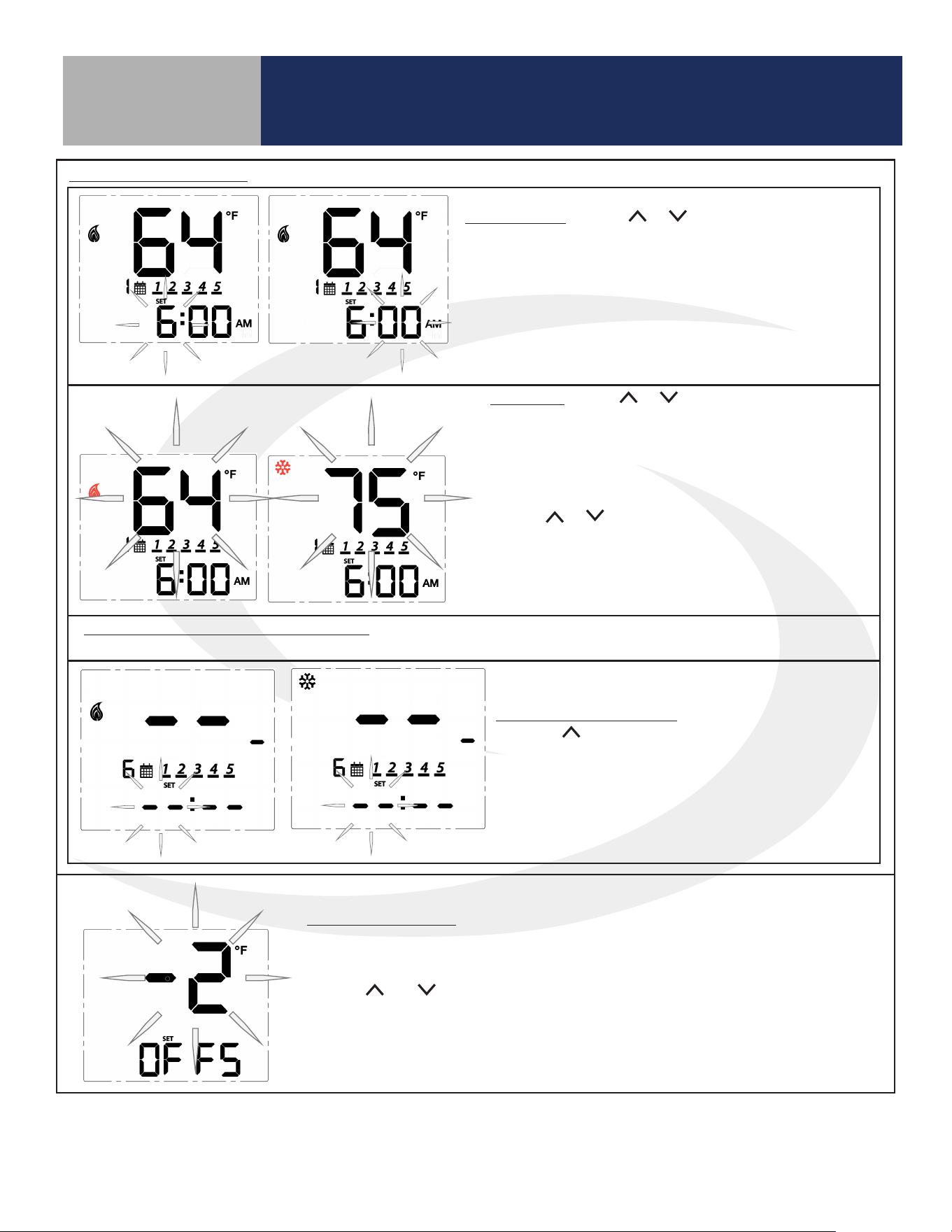
Time Interval: Use the or keys to set the start time
for each time interval, displayed next to the calendar icon.
1st: Set the hour for the time interval start
2nd: Set the minutes for time interval start
Press SELECT to move on to the heating setpoint.
Set Point: Use the or keys to adjust the desired
heating temperature set point for the time interval
displayed.
Press SELECT to accept the set point and move on to
the cooling temperature set point.
Use the or keys to adjust the desired cooling
temperature set point for the time interval displayed.
Press SELECT to accept the set point and move on to
the next interval.
Set points for remaining time intervals: Set the start time and heating and/or cooling temperature for the
remaining interval for a total of 6 intervals.
Skipping a Time Interval: To skip a time interval,
press the key in the hour setting mode until each
of the time and temperature digits change to a “ - “.
When time intervals are completed, the schedule
will return to the first time interval at the scheduled
time.
Configuration
Section 6.0
Schedule (Continued)
Temperature Offset: Change the temperature offset value to adjust the display
of the sensed temperature. This will affect the sensor selected by the INT/EXT
sensor setting.
Use the and keys to set the offset in 1°F (0.5°C) increments. The available
range is -6 to 6°F (-3 to 3°C).
Press SELECT to accept the set point and return to the first item in the
Settings Menu.
27
Configuration
Section 6.0
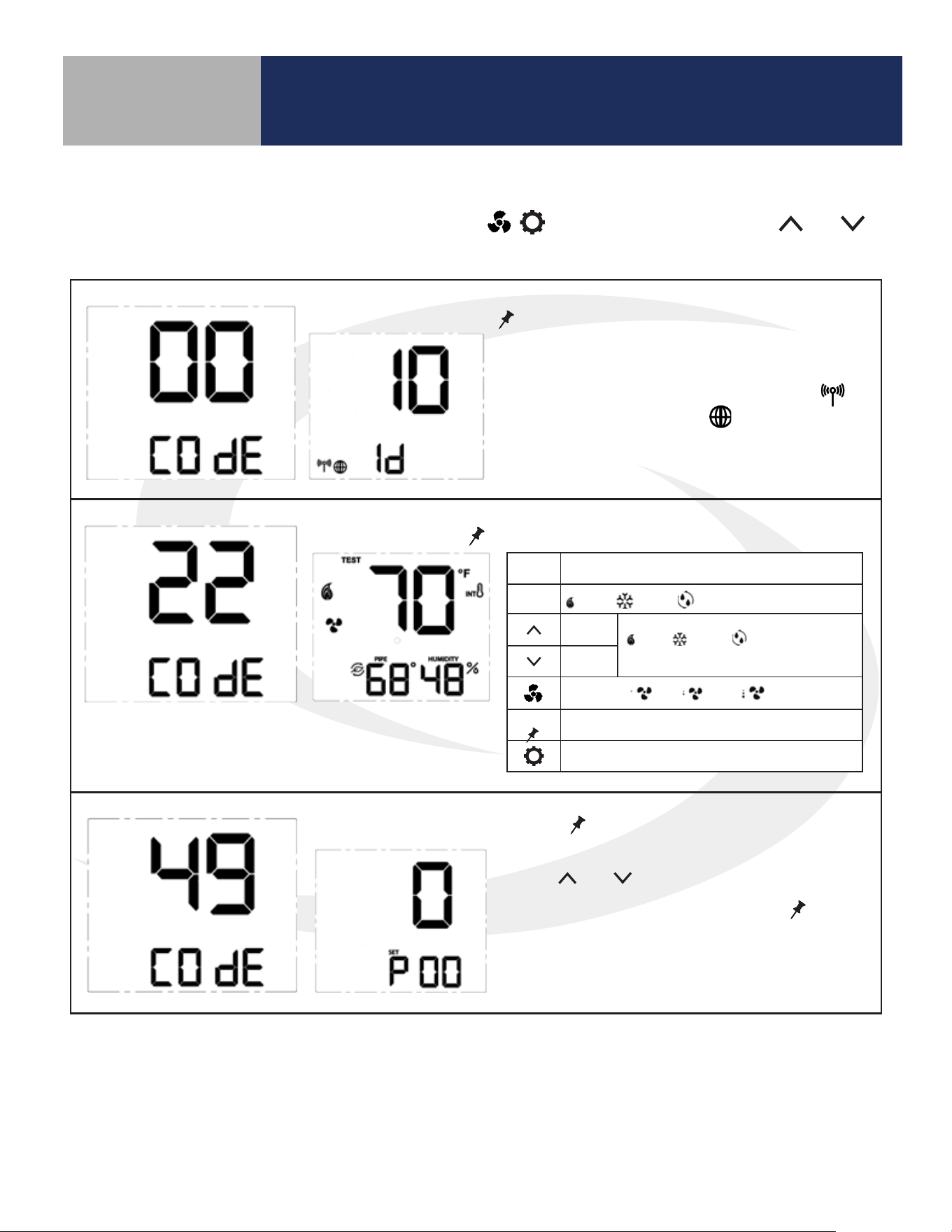
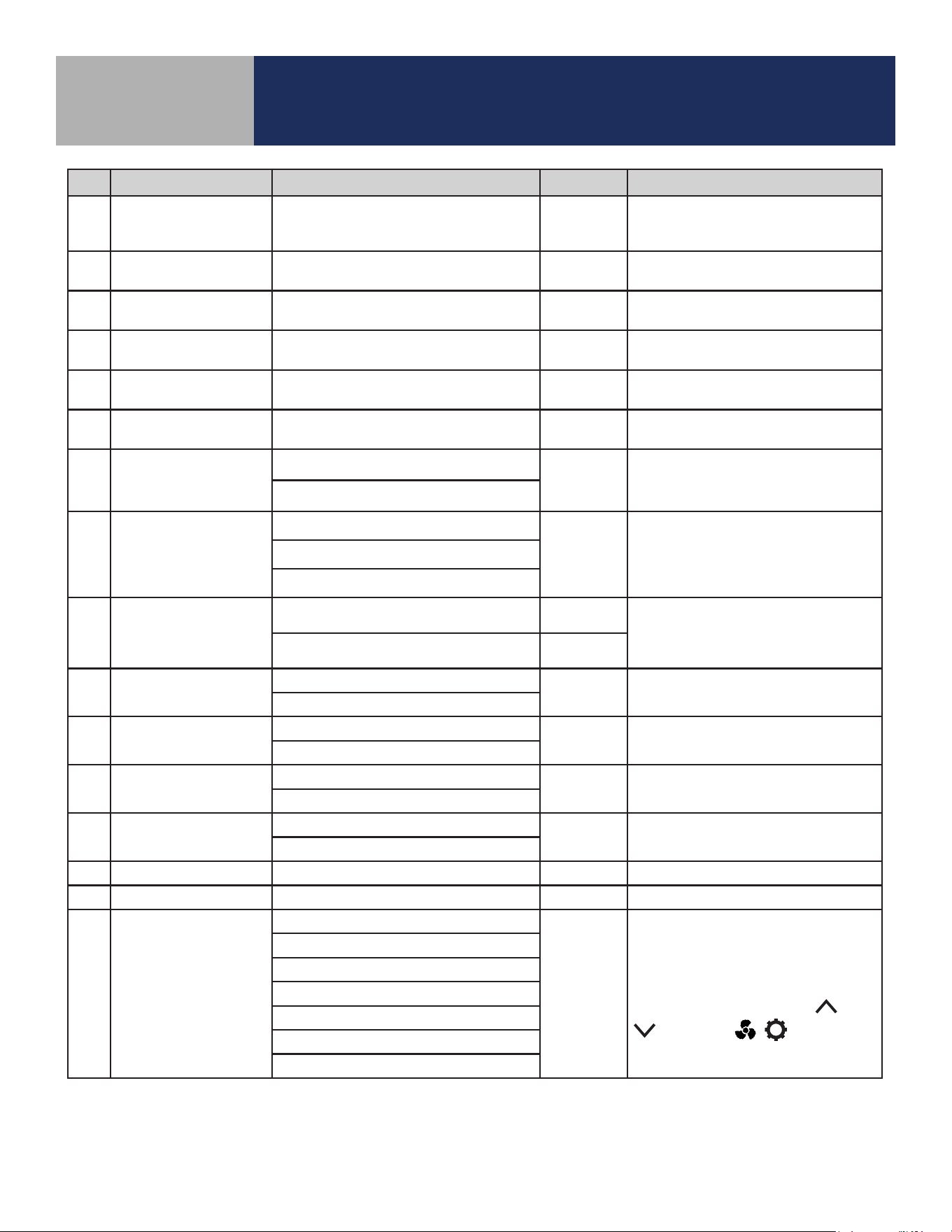
6.2 Special Function Codes
To access special functions, press and hold the MODE, , keys simultaneously. Use the and
keys to scroll through the available codes.
Identify Mode – Press
SELECT
to initiate Identify Mode
A 10 minute timer begins with the screen back-
light flashing. If a network is available, the
icon will flash. The internet will be visible if a
connection is established.
Test Mode – Press
SELECT
to initiate Test Mode
Parameter Setup Mode – Press
SELECT
to initiate Parameter Setup Mode
Use the and keys to change the value of
the parameter that is flashing. Press
SELECT
to
save the current parameter value and advance to
the next parameter. A complete list of parame-
ters is included in Appendix A.
Key Function
MODE
Heat / Cool / Accessory relay select
Turn on
(WY), (YA) or (Ac)
depending on MODE
Turn off
Fan Speed Lo / Med / Hi relay control
SELECT
Toggle HUMIDITY or Zigbee Channel
Exit Test Mode
28
Configuration
Section 6.0
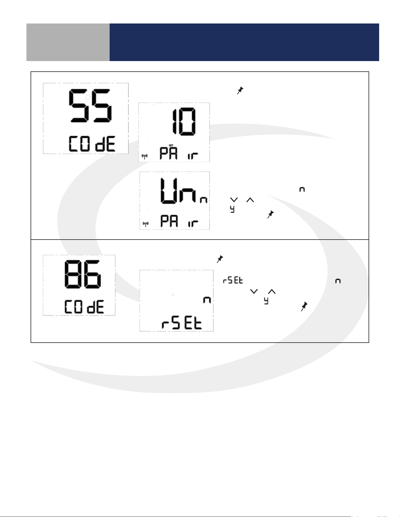
Join/Leave Network – Press
SELECT
to join or leave a network.
Factory Reset - Press
SELECT
to initiate a factory reset.
If the thermostat has not joined a network,
the display will enter the pairing sequence.
Follow the steps under Pairing in Section 3.
If the thermostat is paired with a network,
UnPAir is displayed with “ ” flashing. Press
the or key to change the flashing letter
to “ ”. Press
SELECT
to remove the thermo-
stat from the network.
is displayed with a flashing “ ”.
Use the or key to change the flash-
ing letter to “ ”. Press
SELECT
to reset the
thermostat to all of the factory default
settings.
29
Operation
Section 7.0
7.1 Operating Modes
The Fan Coil Thermostat can be operated in Standalone Mode, Local Mode or Simple Mode depending
on the network and internet connection. The chart below shows how these modes aect the display and
operation of the device.
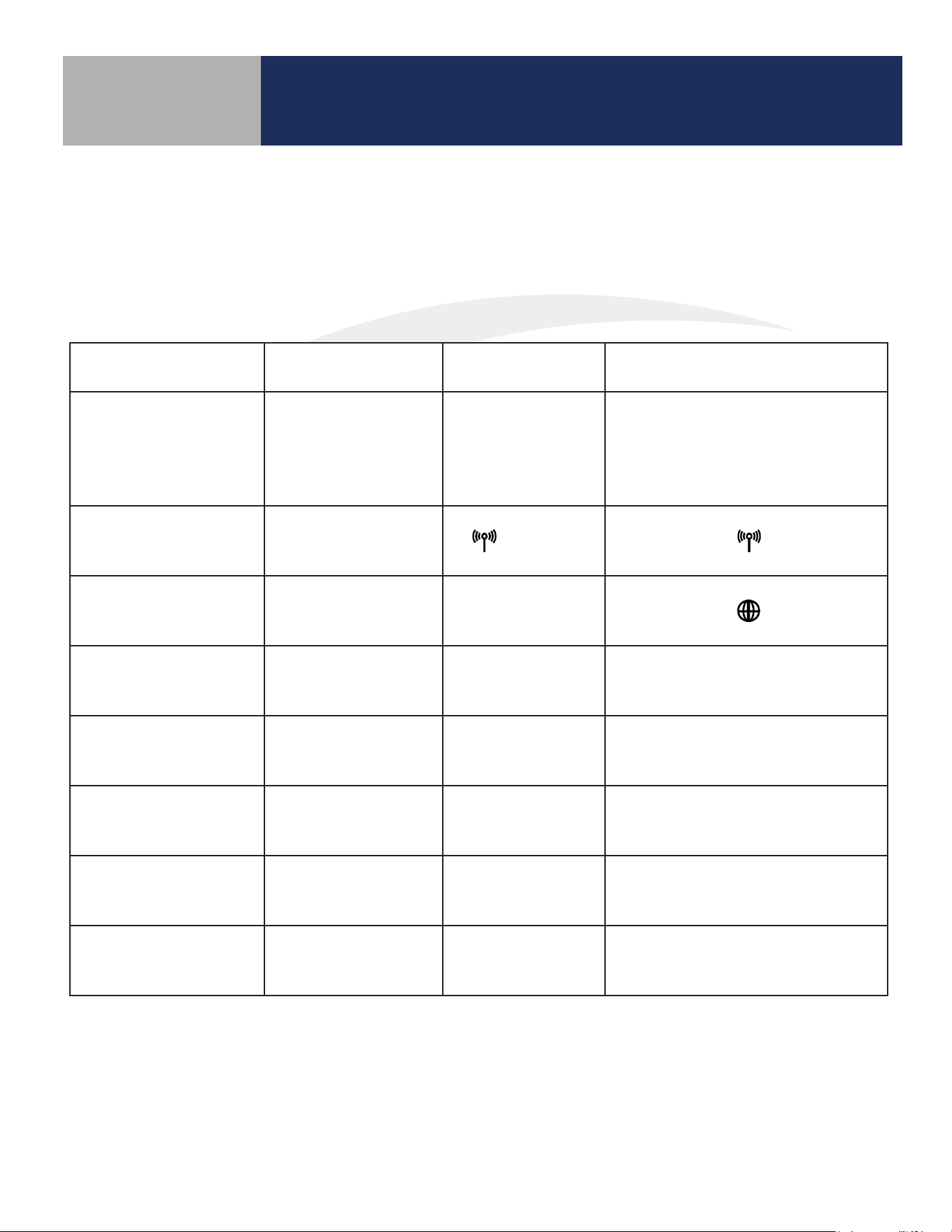
Table 7.1: Operating Modes
Operation Standalone Mode Local Mode Simple Mode
Network State
Thermostat is not
part of a network
Thermostat is part
of a network, dis-
connected from
SG888ZB gateway
Thermostat is connected
to a SG888ZB Gateway
RF Icon Display None
(Flashing)
SALUS Smart Home
Icon
None None
Set Point Change Device Only Device Only
Device, SALUS Smart Home
application or Web
Schedule
In Device,
if enabled
In Device,
if enabled
In SALUS Smart Home service
Change Fan Speed Device Only Device Only
Device, SALUS Smart Home
application or Web
Mode Change
(Heat/Cool/Auto/Off)
Device Only Device Only
Device, SALUS Smart Home
application or Web
Installation Setup Device Only Device Only
Device, SALUS Smart Home
application or Web
30
Operation
Section 7.0
7.2 Programmable Thermostat (Standalone or Local Mode Only)
When in Standalone or Local mode, the default operation of the Fan Coil Thermostat is as a Non-
Programmable Thermostat with no scheduling capability. Changing the value of Parameter P00 (See
Appendix A) to 1, changes the device to Programmable, allowing users to program a wide variety of
schedule options. Instructions for setting up a schedule are covered in Section 6: Conguration.
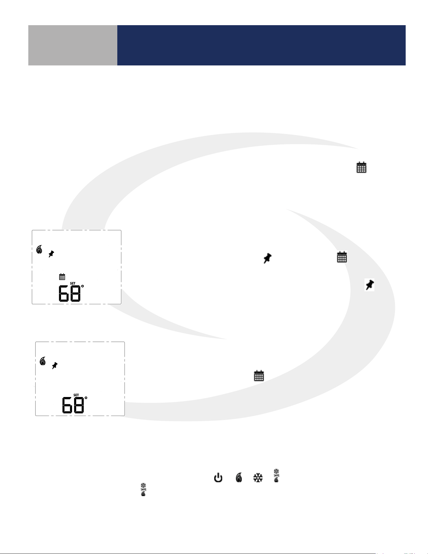
7.3.1 Temporary Hold
To temporarily override the schedule, simply use the ^ or v keys to
change the setpoint. When in Temporary Hold, the LCD display on
the Fan Coil Thermostat will show in addition to the icon. The
schedule will resume when the next scheduled time interval begins.
Change the temperature to the scheduled temperature and the icon
will turn o, indicating that the thermostat is following the schedule.
7.3.2 Permanent Hold
Once in Temporary Hold, press SELECT to toggle between temporary
and permanent override. When in permanent override, the LCD display
on the Fan Coil Thermostat the icon will turn o. The schedule will
be suspended until the user returns it to the schedule changing the
temperature to the scheduled temperature and pressing SELECT.
7.4 Heating/Cooling Modes
Heating/Cooling mode selection works the same for both programmable and non-programmable Fan
Coil Thermostats. Parameter P02 (see appendix) determines which heating and/or cooling modes are
available. Pressing the MODE key, will cycle through
depending on Parameter P02
(Appendix A) settings. When in mode, the Fan Coil Thermostat will maintain a temperature between
the heating and cooling setpoints.
7.3 Set Point Override
While following a temperature schedule in any mode, the Fan Coil Thermostat will display the icon.
The schedule may be overridden temporarily until the next programmed time period, or permanently
until the user returns the device to the programmed schedule.
31
Operation
Section 7.0
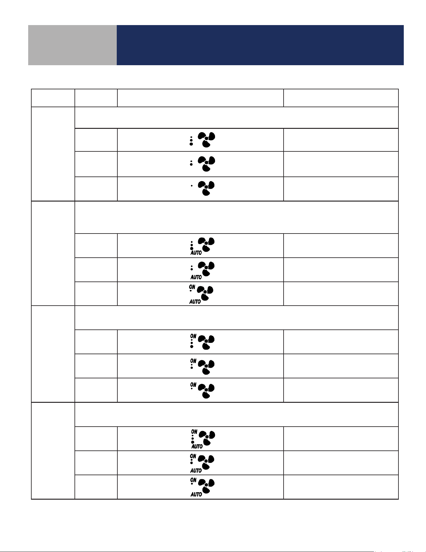
7.5 Fan Modes
Fan Mode Speed Display Output Terminal
Fan output is only activated when a thermostat call is present (On Call Fan).
When a call is present the fan runs at the selected speed.
High
Gh
Medium
Gm
Low
Gl
AUTO
Fan output is only activated when a thermostat call is present (On Call Fan).
When a call is present the fan speed is determined by the TPI/Span algorithm selected in
Parameter 23 (See Appendix A).
High
Gh
Medium
Gm
Low
Gl
ON *
Fan output is constant at the selected speed.
The fan will remain running when a thermostat call is not present.
High
Gh
Medium
Gm
Low
Gl
ON-AUTO *
Fan output is only activated when a thermostat call is present (On Call Fan). When a call is present, the
fan speed is determined by the TPI/Span algorithm selected in Parameter 23 (See Appendix A).
High Gh
Medium Gm
Low Gl
* When in constant fan output, the fan coil will automatically switch to On Call Fan 2 or 4 hours after the
initial call for heat or cool is satised (P35).
32
Operation
Section 7.0
7.6 Accessory Function
Terminals Ac1 and Ac2 on the Fan Coil Thermostat provide output to an accessory such as a Humidier,
Dehumidier, Heat Recovery Ventilator (HRV) or Energy Recovery Ventilator (ERV). The built-in humidity
monitor continually samples humidity at the thermostat and will operate a humidier or dehumidier to
maintain the specied value. The following table shows the function of the accessory output depending on
which accessory is selected under parameter 22 (See Appendix A).
Parameter P22 Setting Operation of Ac1/Ac2 dry contacts
0 (No Function) Open
1 (Humidifier)
Closed when humidity is at
or below the set point
Open when the humidity
exceeds the set point
2 (Dehumidifier)
Closed when humidity is at
or above the set point
Open when the humidity is
less than the set point
3 (ERV/HRV) Closed when fan relay is on Open when fan relay is off
The icon is displayed when the Ac1/Ac2 dry contacts are closed.
33
7.7 AWAY Mode
Fan Coil Thermostat terminals Ts and Tc are used to initiate or terminate an Away state in the device. The
Ts/Tc contact closure is congured by P16 as a Normally Open or Normally Closed contact, or as an input
to be ignored.
P16
Ts/Tc
Status
P21
0 (Setback Mode) 1(Off Mode)
0 (Disabled) Ignored Inactive Inactive
1 (Normally Closed)
Open Setback Off
Close Inactive Inactive
2 (Normally Open)
Open Inactive Inactive
Close Setback Off
Operation
Section 7.0
A contact state change detected between the two terminals will initiate the Away timers (P19 or P20)
and once the timers expire, the device will enter or exit AWAY mode (indicated by the “person in
doorway” icon). The timers are canceled if the contact input changes while the timers are active.
If Setback is selected when in AWAY mode (P21), the Setback set points (P17 and P18) will be in eect
(indicated by “leaf” icon), overriding any schedules.
34
Troubleshooting
Section 8.0
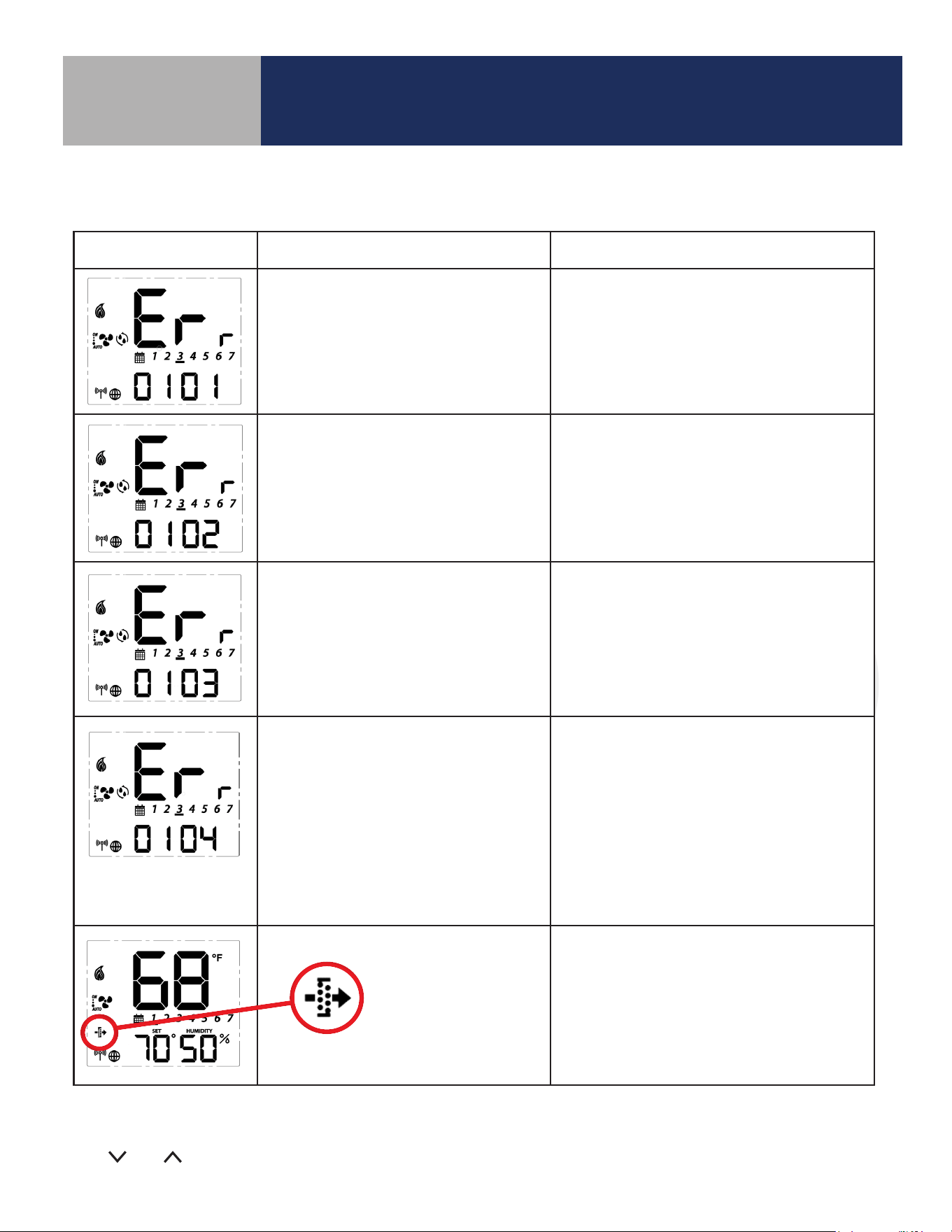
Error Message Description Corrective Action
Error 01: Pipe supply sensor circuit is
open, or pipe supply sensor is not
connected. The pipe supply sensor must
be used if Parameter P02 = 3 or 4 (See
Parameters Appendix A).
• Check connection of pipe supply sensor
to terminals
• Replace sensor
Error 02: Pipe supply sensor circuit is
shorted, or pipe supply sensor damaged.
The pipe supply sensor must be used if
Parameter P02 = 3 or 4 (See Parameters
Appendix A).
• Check connection of pipe supply sensor
to terminals
• Check for shorts in pipe supply sensor leads
• Replace sensor
Error 03: Room temperature sensor
circuit is shorted, or room temperature
sensor damaged.
• If sensor is set to External (Settings), and
Parameter 12 (Appendix A) is set to external
sensor, check for short circuit
• If sensor is set to Internal (default), replace
thermostat or use external sensor
Error 04: Room temperature sensor
circuit is open.
• If sensor is set to Internal (Default), replace
thermostat or use external sensor
• If sensor is set to External (Settings), and
Parameter 12 (Appendix A) is set to external
sensor, check wiring or assure sensor is
connected.
• If sensor is set to External and Parameter 12
is set to Zigbee remote, go through the
“Find & Bind” sequence defined in the IOM.
Error 05: Filter is clogged • Change filter
The following error messages are displayed to identify issues when certain conditions occur.
Table 8.1: Error Messages
For Errors 01-04 the display will alternate between the message above and the Home Screen. The total
number of errors (shown 01 above) will be the rst two digits displayed. If more than 1 error exists, press
the and keys to review each error.

35
Installer Notes
Section 9.0
36
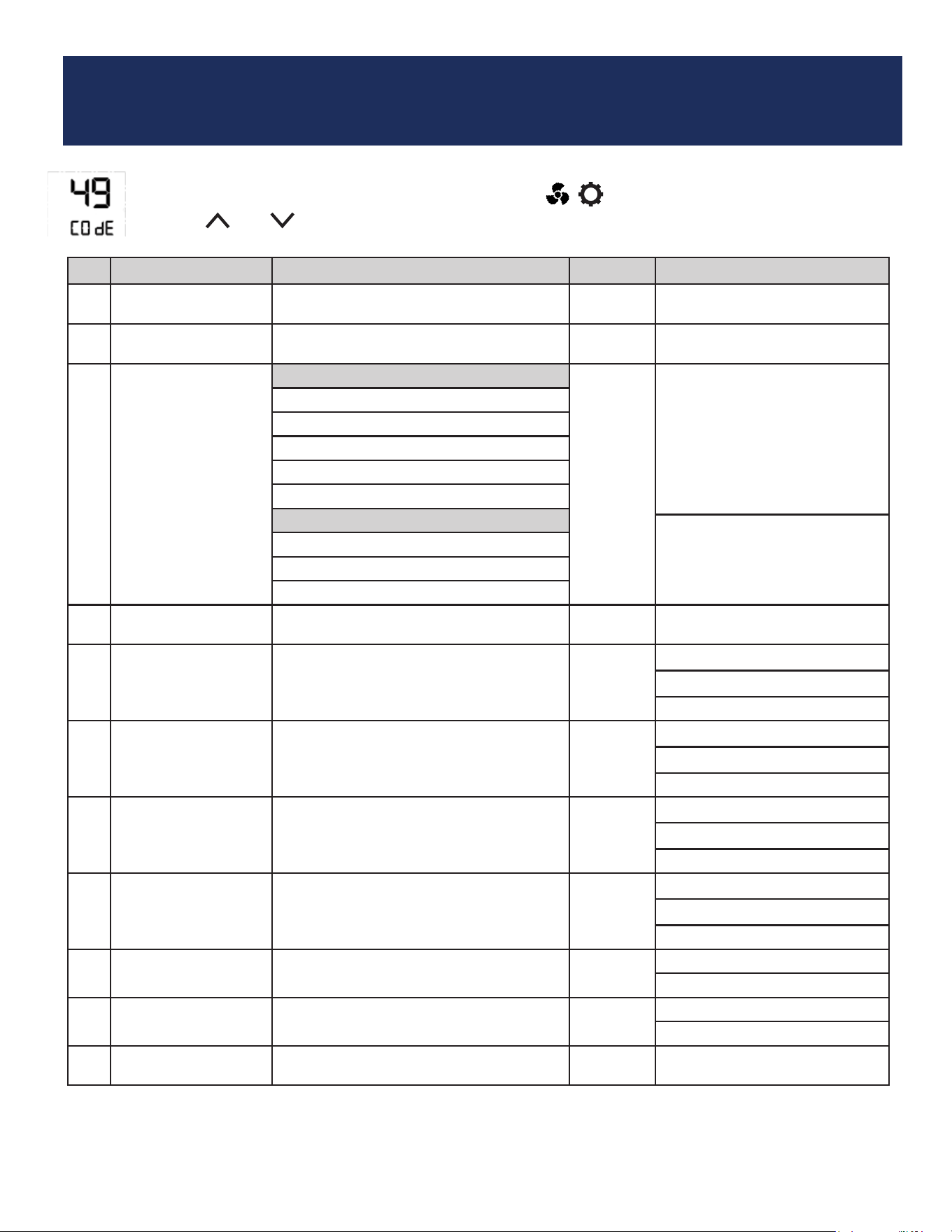
Appendix A - Parameter List
P Name Values Default Description/Comment
P00 Type of thermostat
0 = Non-Programmable
1 = Programmable
0
P01 Fan Coil Type
0 = 2 Pipe
1 = 4 pipe
1
P02 Heat/Cool Option
For 2 Pipe
3
Option #3 & #4 in the 2 pipe
configuration require the pipe
sensor (sold separately) to be
connected
0=Heat Only
1=Cool Only
2 = Heat or Cool Manual changeover
3 = Heat or Cool Seasonal changeover
4 = Heat or Cool with Auxiliary Heat
For 4 Pipe:
2 = Heat or Cool Manual changeover
3 = Heat, Cool or Auto changeover
4 = Auto changeover only
P03 Valve Type
0 = Normally Closed Valve
1 = Normally Open Valve
0
P04 Max. heating setpoint 41 to 92°F (5 to 33.5°C)
92°F
(33.5°C)
Not displayed if P02 = 1
P05 < P04
P04 ≤ P06-1.5°C
P05 Min. heating setpoint 41 to 92°F (5 to 33.5°C)
41°F
(5°C)
Not displayed if P02 = 1
P05 < P04
P05 ≤ P07-1.5°C
P06 Max. cooling setpoint 44 to 95°F (6.5 to 35°C)
95°F
(35°C)
Not displayed if P02 = 0
P07 < P06
P06 ≥ P04+1.5°C
P07 Min. cooling setpoint 44 to 95°F (6.5 to 35°C)
44°F
(6.5°C)
Not displayed if P02=0
P07 < P06
P07 ≥ P05+1.5°C
P08
Protection heating
setpoint
OFF or 41 to 92°F
(OFF or 5 to 33.5°C)
41°F
(5°C)
If not OFF, P05 < P08 < P04
P08 < P09
P09
Protection cooling
setpoint
OFF or 44 to 95°F
(OFF or 6.5 to 35°C)
OFF
If not OFF, P07 < P09 < P06
P08 < P09
P10
Offset of internal
sensor
±6°F - 1°F increments
(±3°C - 0.5°C increments)
0°F
(0°C)
To change parameters, press and hold the MODE, , keys simultaneously.
Use the and keys to scroll to “49” and press SELECT.
37
Appendix A
Section A-1
P Name Values Default Description/Comment
P11
Offset of external
sensor
±6°F - 1°F increments
(±3°C - 0.5°C increments
0°F
(0°C)
P12 External sensor
0 = External sensor
0
Standalone mode: P12 = 0
Set to EXT with key
1 = Zigbee remote sensor
P13 Pipe sensor
0 = Analog input
0
Displayed only if P01=0 and
P02=3 or 4 (2-pipe with sea-
sonal changeover or auxiliary
heat), which requires the pipe
sensor (sold separately) to be
connected.
1 = Normally open, default mode is Heat
2 = Normally open, default mode is Cool
3 = Normally closed, default mode is Heat
4 = Normally closed, default mode is Cool
P14
Pipe sensor threshold
for cooling
50 to 77°F increment 1°F
(10 to 25°C increment 0.5°C)
50°F
(10°C)
P15
Pipe sensor threshold
for heating
81 to 95°F increment 1°F
(27 to 35°C increment 0.5°C)
86°F
(30°C)
P16 Setback input
0 = Disable
0
1 = Normally closed
2 = Normally open
P17
Setback heating
setpoint
50 to 68°F increment 1°F (10 to 20°C
increment 0.5°C)
15°C
(59°F)
Display only if P16=1/2
P18
Setback cooling
setpoint
23 to 32°C increment 0.5°C
(73 to 90°F increment 1°F)
86°F
(30°C)
Display only if P16=1/2
P19
Setback Unoccupied
to Occupied delay
1 to 3 seconds 1 sec Display only if P16=1/2
P20
Setback Unoccupied
to Occupied delay
2 to 30 minutes 2 mins Display only if P16=1/2
P21
Setback mode or Off
mode when unoccu-
pied
0 = Setback mode
1 Display only if P16=1/2
1 = Off mode
P22 Accessory function
0 = No function
0 Normally Open
1 = Humidifier
2 = Dehumidifier
3 = ERV/HRV
P23 TPI or Span
0 = TPI
1
1 = Span control
P24
Modulation Response
Time
0 = Slow response time
1 Display only if P23=0
1= Fast response time
P25 TPI heat control CPH 3 ~ 12 on/off cycle per hour 6 Display only if P23=0
P26 TPI cool control CPH 3 ~ 12 on/off cycle per hour 3 Display only if P23=0
P27
CPH for Auxiliary
Electrical Heater
3 ~ 12 on/off cycle per hour 6 Display only if P23=0
P28
Set span for heating
using span control
.5° to 2°F increment 0.5°F
(0.25° to 1°C increment 0.25°)
0.5°F
(0.25°C)
Display only if P23=1, device
only display 0.2/0.5/0.7/1.0°C or
0.5/1.0/1.5/2.0°F
38
Appendix A
Section A-1
P Name Values Default Description/Comment
P29
Set span for cooling
using span control
0.5° to 2°F increment 0.5°F
(0.25° to 1°C increment 0.25°)
0.5°F
(0.25°C)
Display only if P23=1, device
only display 0.2/0.5/0.7/1.0°C or
0.5/1.0/1.5/2.0°F
P30
Minimum turn off
time for heating
10 to 300 seconds 10 Display if P02<>1
P31
Minimum turn off
time for cooling
10 to 300 seconds 10 Display if P02<>0
P32 Call start delay From 0 to 15 minutes 0
Delay after determining Call for
Heat/Cool before valve is opened.
P33 Fan turn on delay 0 to 600 seconds 0
Delay to allow coils to reach oper-
ating temp
P34 Fan turn off delay 0 to 180 seconds 0
Delay to circulate residual heat/
cool.
P35
Delay to switch to On
Call Fan after initial
Heat/Cool is satisfied.
0=2 hours
0
1=4 hours
P36 Key lock timing
0 = Manual
0
Note: In Auto mode, keys will
lock after 5 minutes of keypad
inactivity.
1 = Auto (lock keys after 5 minutes)
2 = Unlock
P37
Enable/Disable User
Unlock in Simple
mode and Local
mode
0 = user can unlock by ^ and v 0
In Standalone Mode, user can
unlock by ^ and v regardless P37
setting
1 = user cannot unlock by ^ and v
P38 Service filter
OFF
OFF
1 to 99 x 100 operating hrs (e.g. 99
= 9,900 oper. hrs)
1 to 99 (99 means 9900hrs = 99*100)
P39
Status after power
outage
0 = Off mode
1
Thermostat will turn Off or be
restored to Last configuration.
1 = Last configuration
P40
DST
Daylight saving time
0: Disable
1
Used for local mode and stand-
alone mode
1: Enable
P41 Purge Function
0: Disable
1 P01 = 0 (2-Pipe) only
1: Enable
P42 Purge Time 1-7 3 Minutes to purge
P43 Purge Wait 6-36 24 Hours of inactivity before purge
P44 Key lock type
1: Lock HVAC only
7
HVAC = Mode and set point
Fan = fan button
Settings = Settings button
Combination key pressing and
, or MODE, , will not be
locked at any time.
2: Lock Fan only
3: Lock HVAC and Fan
4: Lock Settings
5: Lock Settings and HVAC
6: Lock Settings and Fan
7: Lock All