FIG. PART NO. DESCRIPTION OF PART NO. REQ.
1 23-66-0030 Switch On/Off (1)
2 22-33-0025 Capacitor (1)
3 23-16-0010 Insulation Insert (1)
4 31-15-0010 Capacitor Cover (1)
5 06-82-2295 8-32 x 3/8" Screw T-20 (2)
6 06-97-0050 Lockwasher (1)
7 43-54-0025 Switch Guard (1)
8 43-33-0020 Hose Fitting (1)
9 42-96-0010 Filter Jar (1)
10 45-80-0010 Check Valve (1)
11 43-44-0025 Jar Gasket (1)
12 43-46-0010 Vacuum Gauge (1)
13 43-31-0020 Filter Core (1)
14 43-31-0030 Filter Felt (4)
16 42-92-0080 Manifold Cover (1)
17 43-33-0010 Tee Fitting (1)
18 43-33-0015 Fitting (1)
19 43-16-0020 Eccentric and Bearing Assembly (1)
20 06-83-0010 1/4-28 Set Screw (1)
21 06-75-2105 10-24 x 3/4" Hex Socket Screw (1)
22 44-94-0010 Connecting Rod Assembly (1)
23 42-52-0055 Motor End Cap (1)
24 06-82-5575 10-24 x 7/8" Screw T-25 (4)
25 06-82-5580 10-24 x 1-1/4" Screw T-25 (2)
26 43-62-0015 Handle (1)
27 34-40-0100 Head Gasket (1)
28 43-64-0127 Head (1)
29 --------------- Valve Restriant (1)
30 14-46-0050 Valve Plate Assembly (1)
31 --------------- Valve Keeper Strip (1)
32 --------------- Valve Flapper (2)
33 --------------- 6-32 x 3/16" Slotted Head Screw (2)
34 --------------- Valve Plate Kit (1)
35 34-40-0105 O-Ring (1)
36 22-84-0025 Fan (1)
37 06-82-2295 8-32 x 3/8" Screw T-20 (2)
38 43-52-0070 Front Cover Grille (1)
39 42-36-0015 Bracket (1)
40 22-90-0020 Vibration Mount Grommet (4)
41 06-81-1080 10-24 x 5/8" Hex Head Machine Screw (4)
42 06-97-0060 Lockwasher (4)
43 06-55-0100 Hex Nut (4)
44 06-97-0055 Lockwasher (4)
45 14-37-0122 Hose Assembly (1)
46 43-75-0020 Hose (1)
47 43-33-0020 Hose Fitting (1)
48 42-90-0050 Female Coupling (1)
49 45-36-0050 Spacer (1)
50 --------------- Cord Set (1)
51 10-20-6900 Warning Label-Filter Jar (Not Shown) (1)
52 10-20-6905 Warning Label-Head (Not Shown) (1)
53 10-20-6910 Arrow Decal (Not Shown) (1)
54 10-20-6920 Warning Label-Capacitor Cover
(Not Shown)
(1)
55 12-70-0145 Stator Label (Not Shown) (1)
56 --------------- Pump Service Tool (Not Shown) (1)
Jan. 2001
54-34-0250
SEE BELOW
908A
49-50-0200
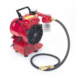
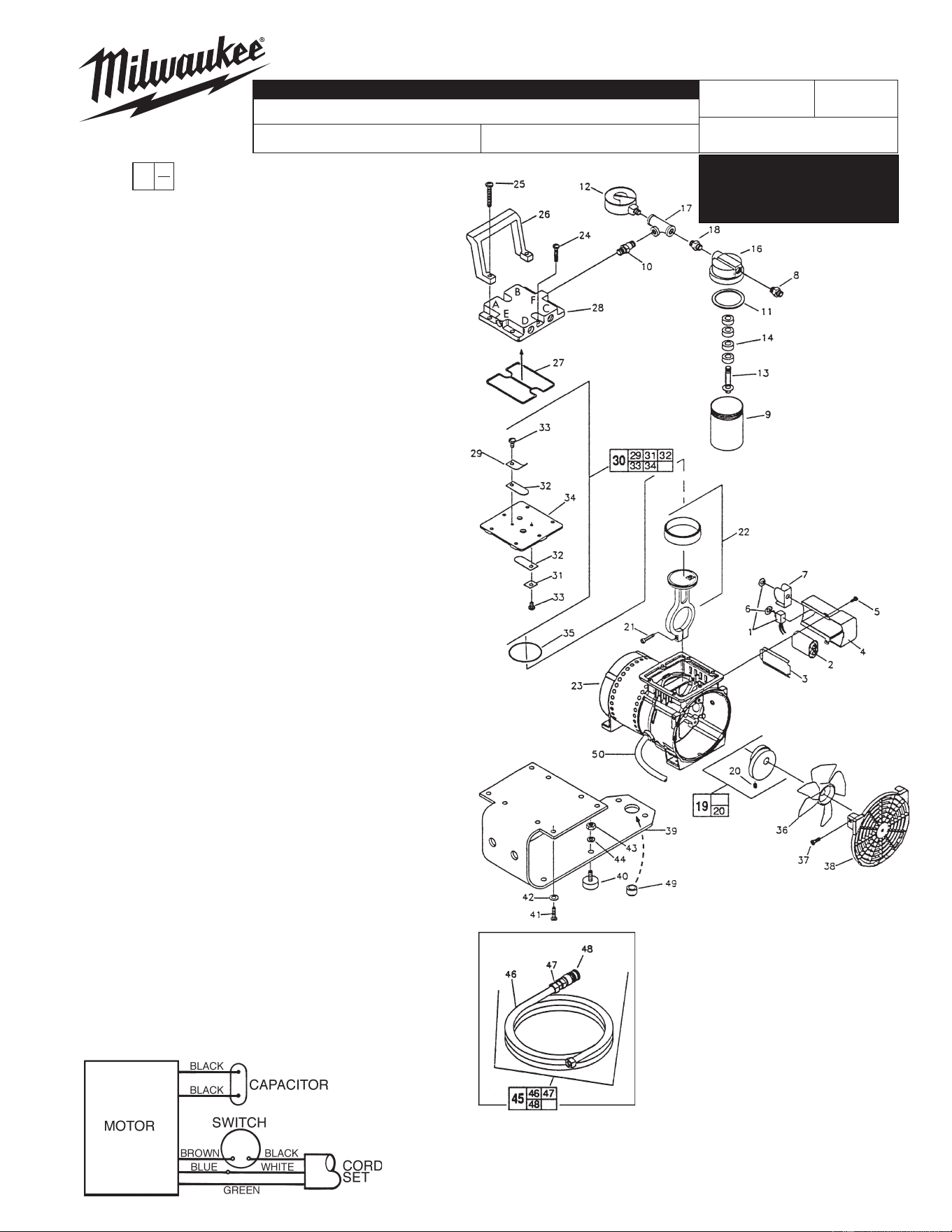
VACUUM PUMP ASSEMBLY
Note: Instructions below are based on the
user facing the pump, with the cord on the
left side and the capacitor on the right side.
1. Indent on top of connecting rod
assembly, #22 (44-94-0010), should
face toward fan.
2. Clamp ring on fan, #36 (22-84-0025),
must face in towards motor.
3. Ribs on valve plate assembly,
#30 (14-46-0050), will face down toward
connecting rod assembly, #22 (44-94-
0010), Valve on top side should be
closer to cord side than capacitor side.
4. The letter "E" on the head, #28 (43-64-
0125), should be on the cord side of the
pump for proper orientation.
00
EXAMPLE:
Component Parts (Small #)
Are Included When Ordering
The Assembly (Large #).
0
WIRING INSTRUCTION
REVISED BULLETIN DATE
SERVICE PARTS
BULLETIN NO.
SPECIFY CATALOG NO. AND SERIAL NO. WHEN ORDERING PARTS
CATALOG NO.
SERIAL
NUMBER
MILWAUKEE ELECTRIC TOOL CORPORATION
13135 W. LISBON RD., BROOKFIELD, WI 53005
Drwg. 3
Assemble Vacuum Gauge / Filter Jar
as shown, for models with a Head
(28) that has port "F" threaded ONLY .
See reverse side for models with
threaded ports on both "C" and "F".
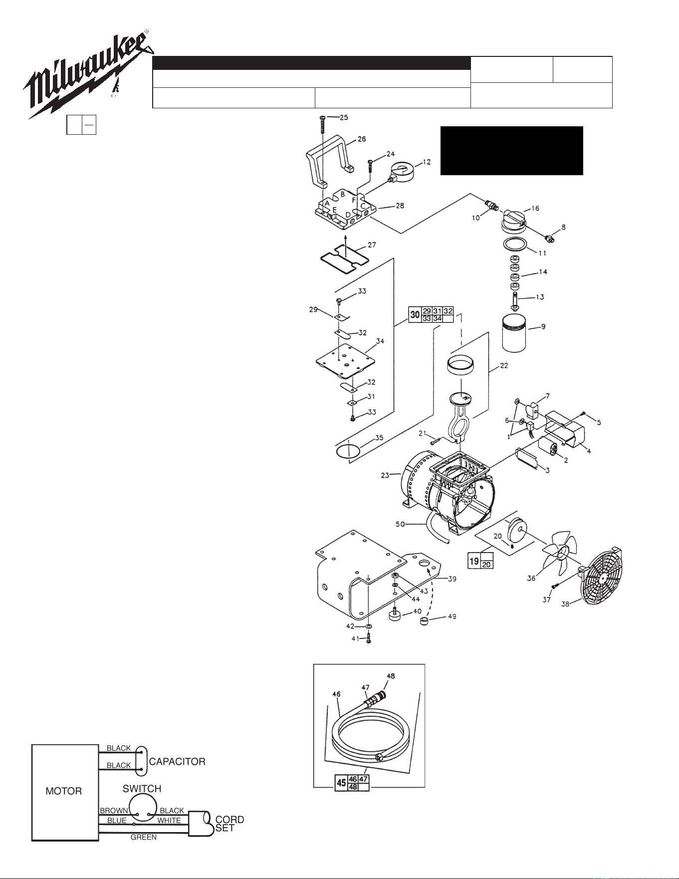
FIG. PART NO. DESCRIPTION OF PART NO. REQ.
1 23-66-0030 Switch On/O (1)
2 22-33-0025 Capacitor (1)
3 23-16-0010 Insulation Insert (1)
4 31-15-0010 Capacitor Cover (1)
5 06-82-2295 8-32 x 3/8" Screw T-20 (2)
6 06-97-0050 Lockwasher (1)
7 43-54-0025 Switch Guard (1)
8 43-33-0020 Hose Fitting (1)
9 42-96-0010 Filter Jar (1)
10 45-80-0010 Check Valve (1)
11 43-44-0025 Jar Gasket (1)
12 43-46-0010 Vacuum Gauge (1)
13 43-31-0020 Filter Core (1)
14 43-31-0030 Filter Felt (4)
16 42-92-0080 Manifold Cover (1)
19 43-16-0020 Eccentric and Bearing Assembly (1)
20 06-83-0010 1/4-28 Set Screw (1)
21 06-75-2105 10-24 x 3/4" Hex Socket Screw (1)
22 44-94-0010 Connecting Rod Assembly (1)
23 42-52-0055 Motor End Cap (1)
24 06-82-5575 10-24 x 7/8" Screw T-25 (4)
25 06-82-5580 10-24 x 1-1/4" Screw T-25 (2)
26 43-62-0015 Handle (1)
27 34-40-0100 Head Gasket (1)
28 43-64-0127 Head (1)
29 --------------- Valve Restriant (1)
30 14-46-0050 Valve Plate Assembly (1)
31 --------------- Valve Keeper Strip (1)
32 --------------- Valve Flapper (2)
33 --------------- 6-32 x 3/16" Slotted Head Screw (2)
34 --------------- Valve Plate Kit (1)
35 34-40-0105 O-Ring (1)
36 22-84-0025 Fan (1)
37 06-82-2295 8-32 x 3/8" Screw T-20 (2)
38 43-52-0070 Front Cover Grille (1)
39 42-36-0015 Bracket (1)
40 22-90-0020 Vibration Mount Grommet (4)
41 06-81-1080 10-24 x 5/8" Hex Head Machine Screw (4)
42 06-97-0060 Lockwasher (4)
43 06-55-0100 Hex Nut (4)
44 06-97-0055 Lockwasher (4)
45 14-37-0122 Hose Assembly (1)
46 43-75-0020 Hose (1)
47 43-33-0020 Hose Fitting (1)
48 42-90-0050 Female Coupling (1)
49 45-36-0050 Spacer (1)
50 --------------- Cord Set (1)
51 10-20-6900 Warning Label-Filter Jar (Not Shown) (1)
52 10-20-6905 Warning Label-Head (Not Shown) (1)
53 10-20-6910 Arrow Decal (Not Shown) (1)
54 10-20-6920 Warning Label-Capacitor Cover
(Not Shown)
(1)
55 12-70-0145 Stator Label (Not Shown) (1)
56 61-10-0680 Pump Service Tool (Not Shown) (1)
SEE BELOW
908A
49-50-0200
VACUUM PUMP ASSEMBLY
Note: Instructions below are based on the
user facing the pump, with the cord on the
left side and the capacitor on the right side.
1. Indent on top of connecting rod
assembly, #22 (44-94-0010), should
face toward fan.
2. Clamp ring on fan, #36 (22-84-0025),
must face in towards motor.
3. Ribs on valve plate assembly,
#30 (14-46-0050), will face down toward
connecting rod assembly, #22 (44-94-
0010), Valve on top side should be
closer to cord side than capacitor side.
4. The letter "E" on the head, #28 (43-64-
0125), should be on the cord side of the
pump for proper orientation.
00
EXAMPLE:
Component Parts (Small #)
Are Included When Ordering
The Assembly (Large #).
0
WIRING INSTRUCTION
REVISED BULLETIN DATE
SERVICE PARTS
BULLETIN NO.
SPECIFY CATALOG NO. AND SERIAL NO. WHEN ORDERING PARTS
CATALOG NO.
SERIAL
NUMBER
®
Assemble Vacuum Gauge / Filter Jar
as shown, for models with a Head (28)
that has ports "C" and "F" threaded.
See front page for models with
threaded port "F" ONLY.