Read Carefully Before Use
Keep for Future Reference
UM-VPH-0043-V2
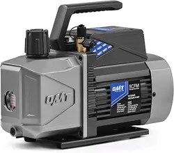
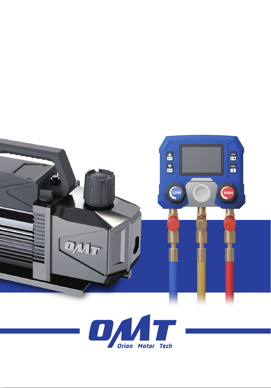
A/C Vacuum Pump
& Gauge Set
User Manual

How did we get our start?
Orion Motor Tech began with a passion for cars. We started out by maintaining family cars in
our home garage but quickly found that affordable quality tools are hard to come by. That’s why
we made it our mission to put durable tools in the hands of do-it-yourself repairmen—so you
can get the job done right.
What makes our products unique?
We have a wide inventory of quality automotive tools and parts, covering almost all makes and
models. As a professional manufacturer, we are driven to make top-quality products affordable
for both professional and amateur mechanics.
Why do we love what we do?
We’re still in love with cars—just like we were back in that old family garage. We hope to pass
that passion on to all our customers, and we still believe in our old motto: You don’t need more
cars in your life. You need more life in your car.
Contact Us
Thank you for choosing our products! If you have any questions or comments,
contact us and we'll address your issues ASAP!
support@orionmotortech.com
https://orionmotortech.com/
@OrionMotorTech
More Life in Every Mile

Contents
1 Safety Information ........................................................................................................... 1
1.1 Disclaimer ................................................................................................................................................ 1
1.2 Symbol Guide ......................................................................................................................................... 1
1.3 General Safety Instructions ................................................................................................................. 2
1.4 PPE Safety Instructions ........................................................................................................................ 2
1.5 Work Area Safety Instructions ............................................................................................................ 2
1.6 Operational Safety Instructions ......................................................................................................... 3
1.7 Disposal Instructions ............................................................................................................................. 4
2 Introduction ...................................................................................................................... 5
2.1 Designated Use ...................................................................................................................................... 5
2.2 Specifications ......................................................................................................................................... 5
2.3 Package List ............................................................................................................................................ 6
2.4 Product Diagram .................................................................................................................................... 7
2.4.1 Vacuum Pump ............................................................................................................................. 7
2.4.2 Gauge Set .................................................................................................................................... 7
2.4.3 Gauge Buttons ............................................................................................................................ 8
2.4.4 Gauge Display ............................................................................................................................. 8
3 Installation ......................................................................................................................... 11
3.1 Preparing the Pump .............................................................................................................................. 11
3.2 Preparing the Gauge Set ..................................................................................................................... 13
3.2.1 Installing Batteries ..................................................................................................................... 13
3.2.2 Zeroing Pressure and Setting Units ...................................................................................... 13
3.2.3 Connecting Hoses ...................................................................................................................... 14
4 Operation .......................................................................................................................... 16
4.1 Connecting the Gauge Set ................................................................................................................. 16
4.2 Evacuating ............................................................................................................................................... 18
4.3 Charging .................................................................................................................................................. 21
4.4 Cleaning ................................................................................................................................................... 25
5 Maintenance ...................................................................................................................... 25
5.1 General Maintenance ............................................................................................................................ 25
5.2 Replacing Vacuum Pump Oil .............................................................................................................. 26
6 Troubleshooting ................................................................................................................ 27
1
1 Safety Information
1.1 Disclaimer
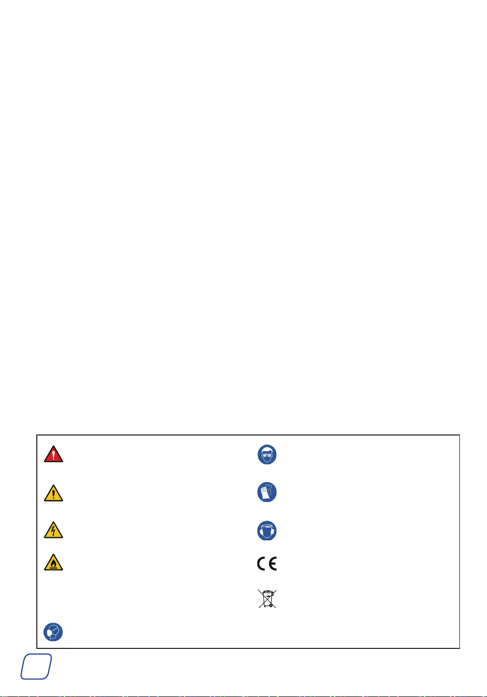
1.2 Symbol Guide
The following symbols appear on this machine’s labels or in this manual:
These items indicate an imminent hazard that WILL
result in death or severe injury if not avoided.
Always wear protective eyewear around this product
during operation.
These items indicate a potential risk that COULD
result in death or serious injury, as well as
significant equipment damage.
Always wear protective gloves around this product
during operation.
These items address similarly serious concerns
about electrical components.
Always wear a hearing protector around this product
during operation.
These items address similarly serious concerns
about fire hazards.
This product is sold in conformity with applicable EU
regulations.
Note These items address tips that help.
This product contains electrical components that
should not be disposed of with regular garbage.
Always wear a respirator around this product during
operation.
Read this disclaimer completely and carefully before
proceeding with the rest of the manual content.
1. Product Modifications
Any modifications or alterations to OMT products void
any warranties and may result in damage or injury. OMT
shall not be liable for any damages resulting from such
modifications or alterations.
2. Compliance with Laws
Customers shall be liable for ensuring that the use of
OMT products complies with all applicable laws and
regulations in their respective jurisdictions. OMT assumes
no responsibility for any violations of laws or regulations
resulting from the use of OMT products.
3. Correct Use
Always use OMT products only as directed in the
accompanying manuals. Failure to follow instructions may
result in injury or damage.
Always ensure the assembly, installation, operation,
maintenance, or repair of OMT products is carried out by
a competent person.
Always make maintenance regularly throughout OMT
products’ lifecycles; you have the liability to keep the
products operating as intended.
Always wear appropriate protective gear.
4. Third-Party Products
OMT shall not be liable for any damages or losses
resulting from the use of third-party products in
conjunction with OMT products. Customers shall refer to
the third-party’s guidelines or/and warranties (if any) for
any third-party products used.
5. Limitation of Liability
OMT shall not be liable for any direct, indirect, punitive,
incidental, special, or consequential damages to property
or life, whatsoever arising out of or connected with the
use or misuse of OMT products. In no event shall OMT’s
liability exceed the value of the products sold.
6. Warranty
Refer to the sales page for the warranty information.
This disclaimer states the entire obligation of OMT with
respect to OMT products. If any part of this disclaimer is
determined to be void, invalid, unenforceable, or illegal,
including but not limited to the warranty disclaimers, liability
disclaimers, and liability limitations set forth above, the invalid
or unenforceable provision will be deemed superseded by
a valid and enforceable provision that most closely matches
the intent of the original provision and the remainder of the
agreement shall remain in full force and effect.
2
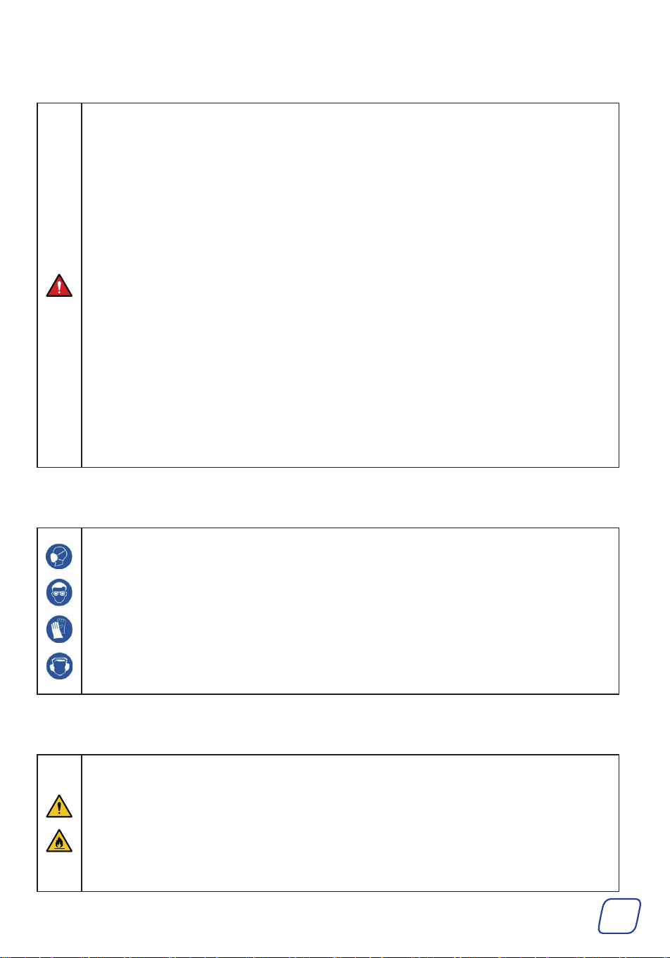
1.3 General Safety Instructions
• Read this manual carefully BEFORE installation, use, and maintenance, and store it for future reference.
• Follow ALL these instructions strictly DURING installation, use, and maintenance. Failure to do so can result in
severe property damage and personal injury.
Provide this manual to anyone who will use this product. Include this manual alongside this product if it is ever
given or sold to a third party. Failure to do so may lead to property damage and personal injury.
• ONLY use this product for its intended purpose, removing gas molecules from a sealed volume to create a partial or
complete vacuum.
It is NOT a toy and should NOT be used playfully or carelessly.
• Any other use NOT explicitly described in this manual may create safety hazards, and void ALL warranties stated
or implied.
• DO NOT use this product while you are tired or under the influence of drugs, alcohol, or strong medication.
• DO NOT allow children under the age of 18, anyone WITHOUT specialized training, persons unfamiliar with this
product, or people whose physical or mental impairment precludes safe use to use this product.
• ALWAYS keep children, bystanders, and pets away during use. Restrict access to your work area as needed.
• DO NOT operate the gauge if there are signs of damage at the housing or hoses.
• DO NOT perform contact measurements on non-insulated, live parts.
• DO NOT store the product together with solvents.
• DO NOT use any desiccants.
• If the gauge falls or another comparable mechanical load occurs, it may cause breakage of the filling tube and
damage the control valve. To ensure safety, replace the filling tube with a new one and check the gauge for
damage.
• This manual ONLY provides instructions about THIS product. For instructions on specific tasks, refer to the
service manual by your A/C system’s manufacturer.
1.4 PPE Safety Instructions
• Wear appropriate personal protective equipment (PPE) as needed:
Breathing, eye, and hand protection for systems that contain refrigerants or other substances capable of
generating harmful gases or causing burns, scalds, frostbite, etc. Protective equipment must meet ANSI (American
National Standards Institute) or OSHA (Occupational Safety and Health Administration) standards.
Hearing protection for noise generated by this product during operation.
• ALWAYS avoid ALL direct contact with the vacuum pump oil.
If contact accidentally occurs with the skin, remove contaminated clothing and rinse the skin with plenty of water.
If contact accidentally occurs with the eyes, IMMEDIATELY flush them with plenty of water for at least 15
minutes while seeking medical attention.
• NEVER swallow the oil, which may cause FATA L problems.
1.5 Work Area Safety Instructions
Make sure your work area meets the following requirements:
• No bystanders, children, or pets
• Helpers wearing necessary PPE
• Well-lit and ventilated but adequately protected from the elements
• Clean and clear of clutter
• Free from flammables, explosives, and heat sources such as firecrackers and open flames. This is especially
important when working with systems that contain refrigerants or other substances that pose the risks of fire,
explosion, carbon monoxide poisoning, etc.
3
1.6 Operational Safety Instructions
• DO NOT operate this product if any component is damaged or malfunctioning. Repair or replace affected
components before further use.
• NEVER replace any components with nonidentical or unauthorized parts.
• For HVAC systems, ALWAYS turn it off BEFORE performing evacuation with this product.
• ALWAYS check that this product’s power cord is undamaged BEFORE use. NEVER attempt to remove ANY
permanently preconnected power cords.
• ONLY use this product with stable, compatible, and well-grounded power sources.
• DO NOT use 3-to-2 prong adapters, ungrounded extension cords, or extension cords of insufficient gauge for
this product’s expected electrical load.
• Stay alert, watch what you are doing, and use common sense when using this product.
• Refrigerant can irritate your eyes, nose, throat, and skin or cause frostbite, heart arrhythmia, unconsciousness,
and EVEN death. Insufficient preparations may cause accidents, leading to serious consequences.
• DO NOT pull the power cord to move this product or modify its power plug.
• If the power goes out while operating this product, IMMEDIATELY unplug it and wait until power is restored
before continued use.
• DO NOT wet or operate this product with wet hands or in highly humid environments.
• If ANY electrical component accidentally becomes wet, IMMEDIATELY disconnect this product from power and
wait for it to completely dry BEFORE resuming use.
• DO NOT run this product WITHOUT the vacuum pump oil or with its oil inlet left open.
• ALWAYS maintain the oil level between the MIN and MAX height marks on the reservoir window during use.
• DO NOT leave this product unattended during use.
• Use EXTREME caution when disconnecting hoses from A/C systems after use. They may still contain some
pressurized refrigerant.
• DO NOT rinse the entire product with tap water, immerse it in water, or expose it to rain.
• If you begin to develop symptoms such as headaches, dizziness, or nausea during use, IMMEDIATELY stop work
and get fresh air.
DO NOT continue work until better ventilation is provided for your work area. This is especially important when
you work on HVAC systems.
• DO NOT maintain this product with harsh abrasives or caustic chemicals.
• NEVER disassemble this product.
• NEVER modify its internal components WITHOUT professional guidance.

4
1.7 Disposal Instructions
Electrical products should not be disposed of with household products. In the EU and UK, according to the European
Directive 2012/19/EU for the disposal of electrical and electronic equipment and its implementation in national laws,
used electrical products must be collected separately and disposed of at the collection points provided for this purpose.
Locations in Australia, Canada, and the United States may have similar regulations.

5
2 Introduction
2.1 Designated Use
This product set is used to remove air and any residual gases from the A/C system and recharge
the A/C system with refrigerant.
2.2 Specifications
Vacuum Pump
Product Model VB130
Power Supply AC 110–120 V, 60 Hz
Rated Power 180 W ± 15%
Evacuation Speed 3.5 cfm 0.1 m³/min
Working Oil Volume Range 10.1–13.5 fl oz 300–400 mL
Compatible Refrigerants A1 and A2L, for example R32, R1234yf, R134a, R22, and R410a
Air Inlet Size 1/4” SAE Male; 1/2”ACME Male
Power Cable Length 55.1 in. 1.4 m
Noise Level ≤ 70 dBA
Dimensions (W×D×H) 10.6 × 4.7 × 8.4 in. 270 × 120 × 215 mm
Net Weight 11.4 lb. 5.2 kg
Gauge Set
Pressure Gauge
Pressure Range − 14.5 to 800 psi − 1 to 55 bar
Temp. Range 14 to 122 ° F -10 to 50 ° C
Hoses
Length 59 in. 1.5 m
Max. Pressure 4000 psi 275.8 bar
Net Weight 6.6 lb. 3 kg
6
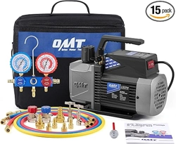
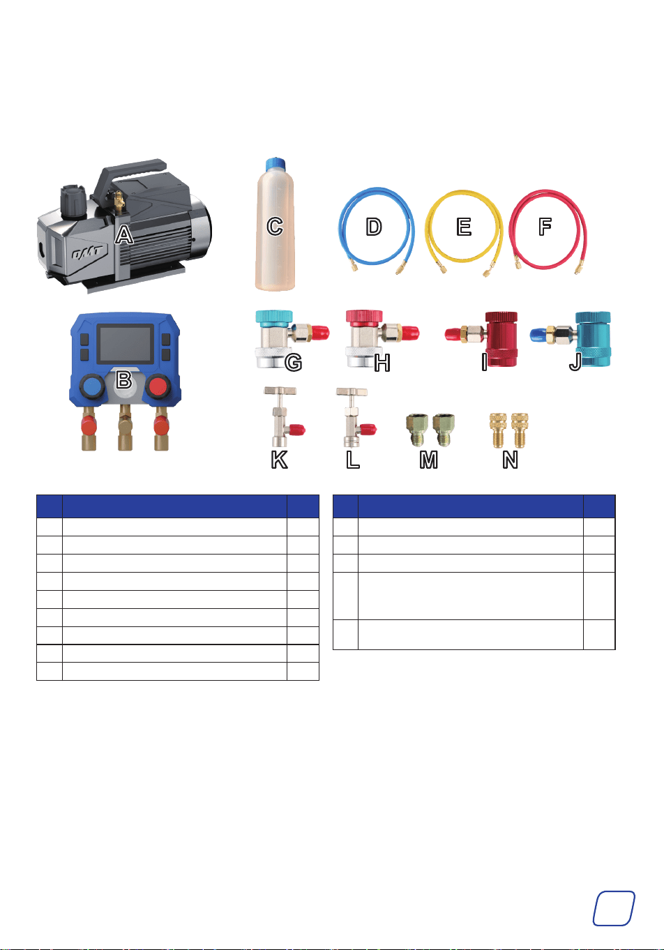
2.3 Package List
After unpacking, check that all parts of this product are present and intact. If any of them are
damaged, ask your local dealer or contractor for a new, identical replacement.
No. Item Qty.
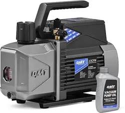
A Vacuum Pump 1
B Digital Pressure Gauge 1
C Vacuum Pump Oil 330 ml 1
D Low-Pressure Hose (Blue) 1
E Evacuation/Charging Hose (Yellow) 1
F High-Pressure Hose (Red) 1
G Low-Pressure Quick Coupler for R134a (Blue) 1
H High-Pressure Quick Coupler for R134a (Red) 1
I Low-Pressure Quick Coupler for R1234yf (Blue) 1
No. Item Qty.
J Low-Pressure Quick Coupler for R1234yf (Red) 1
K R134a Cap Lifter (Self-Sealing Style) 1
L R1234yf Cap Lifter (Self-Sealing Style) 1
M
1/4 SAE to 1/2 ACME Adapters for Cap Lifters
1/4 SAE to 1/2 ACME Reverse Thread Adapter for
Cap Lifters
2
N
1/4 SAE to 5/16 SAE Adapters for R410a
Refrigerant for Home Air Conditioners
2
7
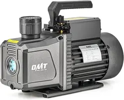
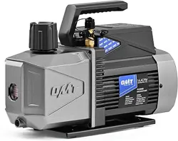
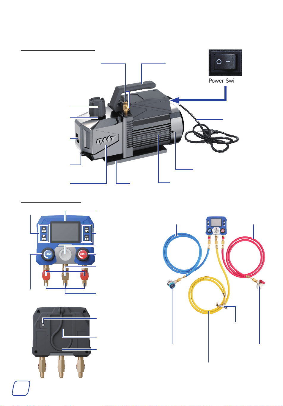
2.4 Product Diagram
2.4.1 VacuumPump
Oil Inlet
(Exhaust Port)
Filter
Motor
Base
Fan Cover
Power Switch
Handle
Power Cable
Gas Inlets
Reservoir
Window
Oil Drain Cap
Oil Tank
2.4.2 GaugeSet
Hook
LCD Screen
Screw For Securing
the Battery Cover
Buttons
Buttons
High-Pressure Valve
Low-Pressure
Valve
Low-Pressure
Hose
Evacuation/Charging
Hose
Low-Pressure
Quick Coupler
High-Pressure
Quick Coupler
Refrigerant
Cap Lifter
High-Pressure
Hose
Viewing Window
Interface Ports
1/4 SAE
Hose Bracket for
Refrigerant Hoses
Battery Cover
8
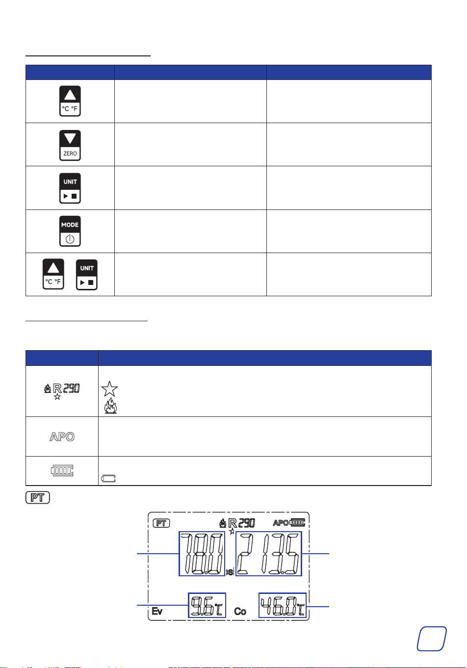
2.4.3 GaugeButtons
Low Pressure
Evaporation Temperature
High Pressure
Cooling temperature
2.4.4 GaugeDisplay
Icons
PT Mode (Pressure and Temperature Measurement Mode)
Icons Functions
Refrigerant
: Commonly Used Refrigerants
: Flammable Refrigerants (Refrigerant safety class greater than A2L)
Auto Power Off
The APO icon lights up to indicate that the automatic shutdown function is
active. The instrument will turn off automatically after 15 minutes of inactivity.
Battery Level
Indicates the battery is almost empty and must be replaced immediately.
Buttons PRESS HOLD
Set refrigerant / set the holding
time.
Set temperature units.
Set refrigerant / set the holding
time.
Reset the pressure.
Set pressure units.
Begin pressure holding / stop pressure
holding.
Switch function modes. Power on and off.
+ N/A
Enable and disable the “Auto Power
Off” function.
9
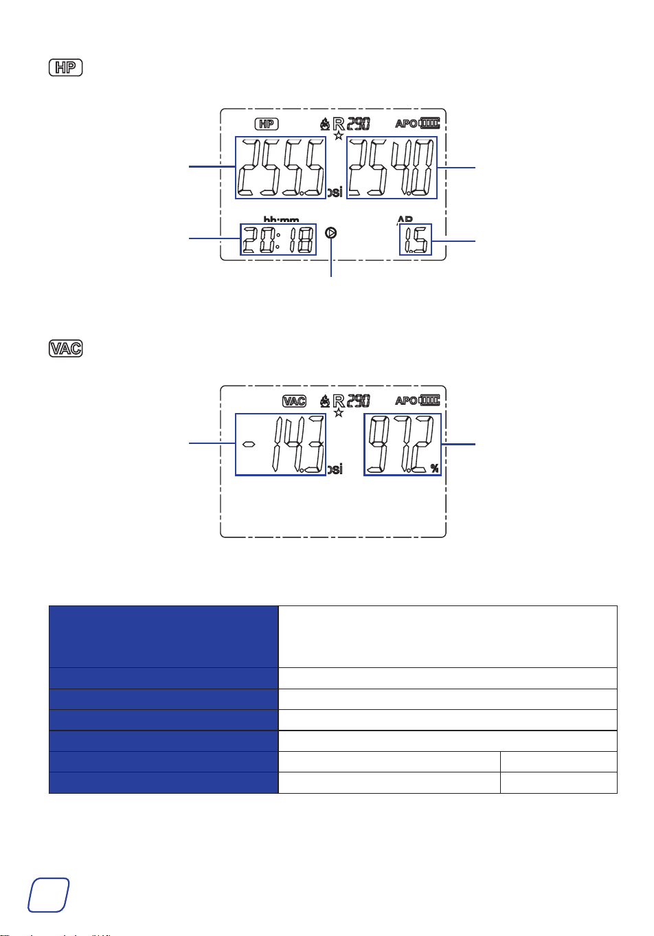
HP Mode (Hold Pressure Mode, ONLY for charging N
2
)
Initial Pressure
Real-Time Pressure
Testing Time
Real-time Pressure
Vacuum Percentage
Under Test
Pressure Dierence
between Real-time
Pressure and Initial
Pressure
VAC Mode (Vacuum Measurement Mode)
Parameters
Pressure Measurement Range
-14.5-800 psi
If the measured pressure exceeds the range, OL is
displayed.
Pressure Display Resolution 0.5 psi
Pressure Measurement Accuracy ± 0.5% FS
Pressure Unit kPa, MPa, psi, inHg, bar, kg/cm2
Temperature Unit ° C, ° F
Operating Temperature -10 ° C-50 ° C 14 ° F-122 ° F
Storage Temperature -20 ° C-60 ° C -4 ° F-140 ° F
10
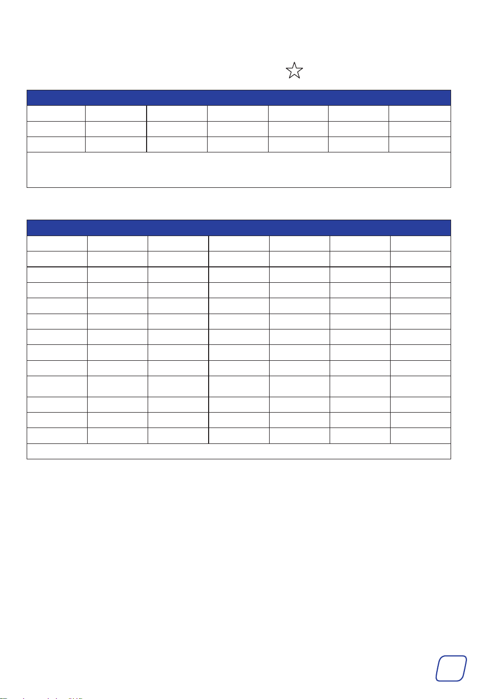
Supported Refrigerants (US NIST Standard Data)
The following 16 refrigerants are commonly used, with displayed below the icon.
16 Commonly Used Refrigerants
R1234yf R134a R22 R23 R290 R32 R404A
R407C R410A R433B R436A R502 R503 R507A
R600 R600A
Note: The commonly used refrigerants are arranged before the less common refrigerants for
quick and easy switching.
The full list of the 88 refrigerants is as below:
Full List of 88 Supported Refrigerants
R113 R114 R115 R116 R12 R123 R1233ZD
R1234ZE R1234YF R124 R125 R13 R134A R14
R141b R143A R152A R170 R22 R227EA R23
R236FA* R245FA* R290 R32 R401A R401b R401C
R402A R402b R403b R404A R406A R407A R407b
R407C R407D R407F R408A R409A R410A R410b
R412A R413A R414A R414B R416A R417A R417C
R420A R421A R421b R422A R422b R422C R422d
R424A R426A R427A R428A R429A R433B R434A
R436A R437A R438A R441A R443A R448A R449A
R450A R452A R452b R453A R454A R454b R455A
R458A R500 R502 R503 R507A R508A R508b
R514A R600 R600A R601A
Note*: Refrigerants R236FA and R245FA are displayed as R236F and R245F.
11
3 Installation
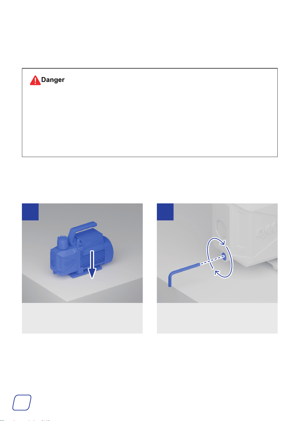
3.1 Preparing the Pump
• Vacuum pump oil is flammable and explosive and MUST be kept away from open flames
and sparks.
• NEVER swallow the oil or touch it with bare skin.
• Wear your dust mask, goggles, work gloves, ear muffs, and any other PPE necessary for
your work area.
• Only use the provided oil or oil meant for vacuum pumps. Using other mechanical oils
could impact the quality and performance of your vacuum.
Tools and Parts Needed:
• Vacuum Pump Oil 46
• M4 Hex Wrench (Not Included)
Place the vacuum pump on a firm, level
surface.
Retighten the oil drain cap using an M4
hex wrench.
1 2
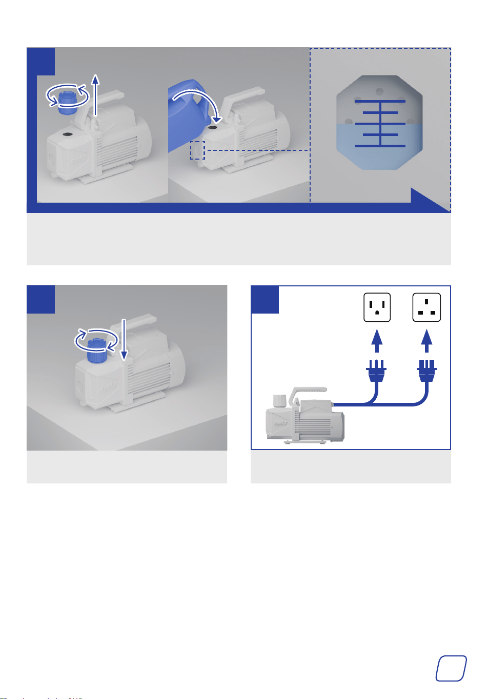
12
Remove the cap of the oil inlet by turning it by hand and add the provided oil until the level is
between the MIN and MAX height marks BEFORE use.
To prevent spills, use a funnel (not included) that fits the oil inlet.
MAX
MIN
3
Add the cap, turning it into place.
Connect the pump to a stable, compatible,
and grounded power source.
4 5
or
US UK
13
3.2 Preparing the Gauge Set
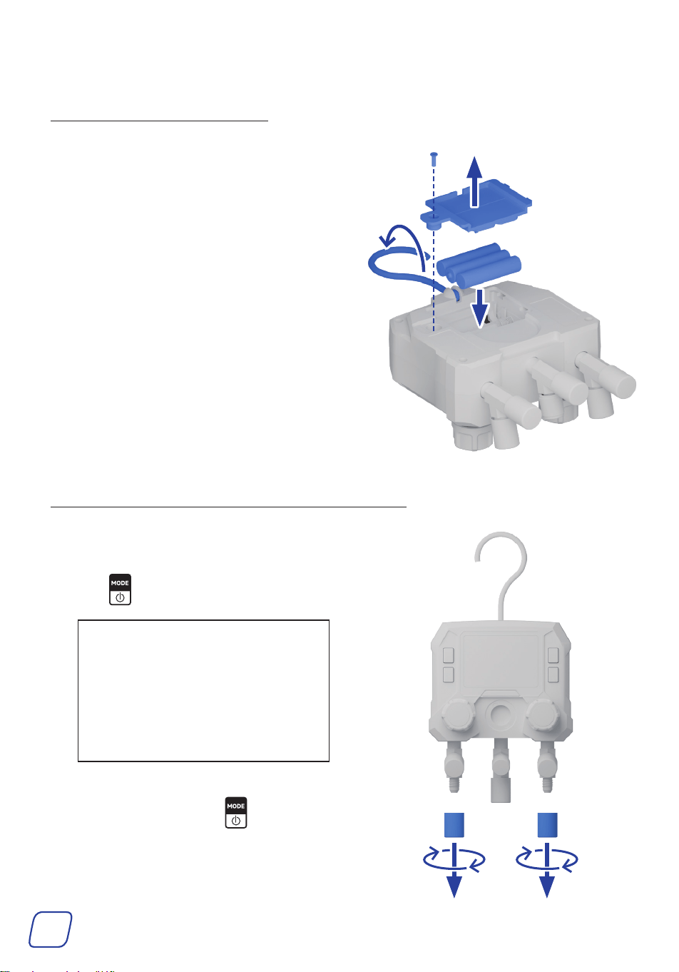
3.2.1 InstallingBatteries
1. Unfold the hook.
2. Remove the fixing screw of the battery
compartment cover using a flathead
screwdriver.
3. Snap open the battery compartment cover
along the groove at the bottom.
4. Insert three AAA batteries into the battery
compartment.
5. Add the previously removed battery
compartment cover and the fixing screw
back.
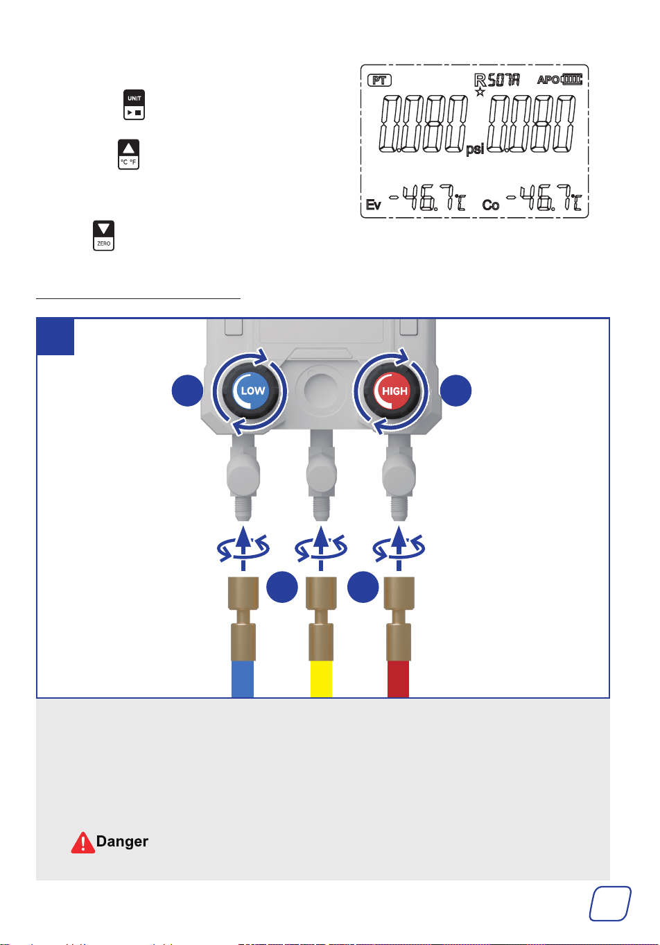
3.2.2 ZeroingPressureandSettingUnits
1. Pull away the protective caps from the
valve ports under the knobs.
2. Hold to turn on the display.
Note:
The screen will turn off after 2
minutes of inactivity. To turn it on,
hold the power button.
The display will automatically turn
off after 15 minutes of inactivity.
3. Ensure the PT mode is displayed as
shown. If it is not, press to switch the
gauge to the PT mode.
14
4. Set units.
a. Press to set the pressure unit.
b. Hold to set the temperature unit.
The change will take effect immediately
and be saved, even after powering off.
5. Hold to reset the pressure as shown.
3.2.3 ConnectingHoses
a.
Turn the valves on the gauge set completely clockwise,
FULLY
closing its low-pressure (LP) and
high-pressure (HP) valves.
b.
Remove the protective caps from the valve ports by turning them counterclockwise and connect
the hoses to the gauge using the hoses’ locking nuts.
The blue LP hose to the port below the LP valve, the red HP hose to the port below the HP
valve, and the yellow evacuation/charging (E/C) hose to the port in the middle.
DO NOT mix hoses in different colors, as they are NOT interchangeable.
1
b b
a a
Hose end WITHOUT
copper cores inside
15
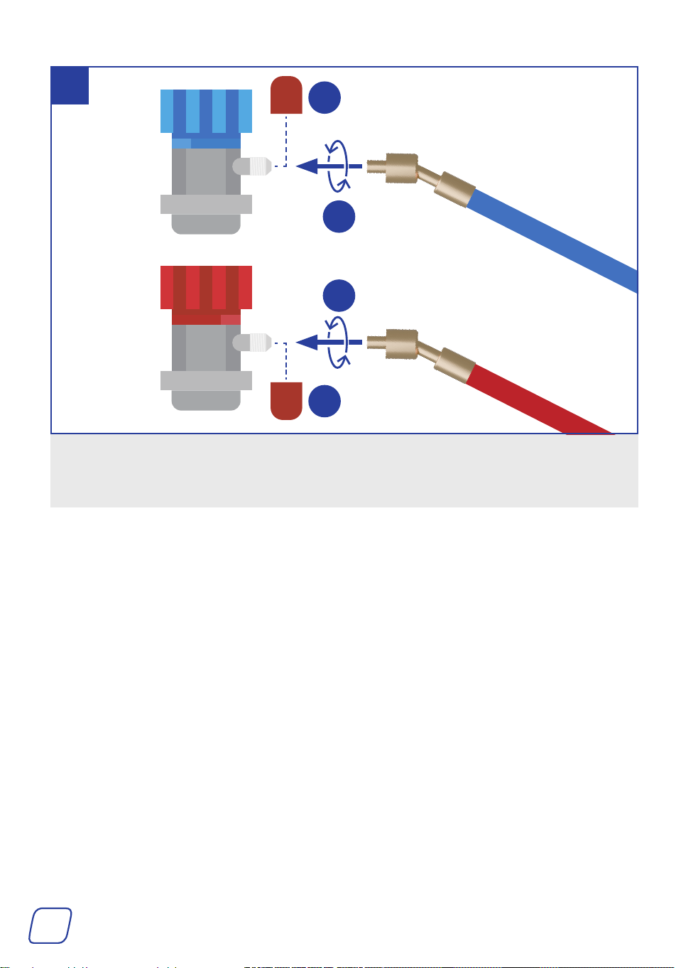
a. Pull away the protective caps from the couplers.
b. Connect the blue and red hoses to their identically colored quick couplers using the hoses’
locking nuts.
2
Hose end WITHOUT
copper cores inside
b
a
a
b
16
4 Operation
• Wear your dust mask, goggles, work gloves, ear muffs, and other PPE necessary for your
work area.
• Know your A/C system and take sufficient training BEFORE using this product for
optimal safety. A lack of training could cause failures and accidents.
• Avoid operating this machine in crowded, poorly lit, or cluttered areas.
• This product is NOT compatible with refrigerants containing ammonia.
• This product must NOT be used in potentially explosive atmospheres.
• Ensure NO explosives or ignition sources nearby.
• Ensure that ALL connections ARE tightly secured.
• BEFORE starting work on an HVAC system, ensure it has been turned off.
• If you have used the pump before, check the pump’s oil volume. If the oil amount is
under the MIN mark, refill it until the level is between the MIN and MAX height marks
BEFORE use.
Check if the pump oil is emulsified and unclean. If it is, replace the oil. For instructions,
see 5.2ReplacingVacuumPumpOil on Page 26.
This chapter uses R134a refrigerant as an example.
Tools and Parts Needed:
The Provided Vacuum Pump Oil 46
or Any Other Equivalent (ISO 100 Or SAE 30)
M4 Hex Wrench
(Optional)
4.1 Connecting the Gauge Set
Identifying the high and the low-pressure ports on your
A/C system is important. Generally, high-pressure ports are
physically bigger and higher than the low-pressure ports.
High-Pressure Port
Low-Pressure Port
17
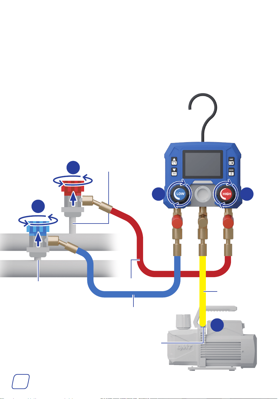
1. Connect the LP hose to the LP port on your A/C system. Make sure the hose is closed by
turning the port of the hose counterclockwise and turning the valve clockwise.
2. Connect the HP hose to the HP port on your A/C system. Again, make sure the hose is closed
by turning the port of the hose counterclockwise and turning the valve clockwise.
3. Connect the E/C hose to the compatible gas inlet port on the vacuum pump.
If your A/C system requires R1234yf refrigerant, use the provided R1234yf Quick Couplers (I&J).
2
1
High-Pressure Hose
Compatible
Gas Inlet Port
High-Pressure Port
Low-Pressure Port
3
1 2
E/C Hose
Low-Pressure Hose
18
4.2 Evacuating
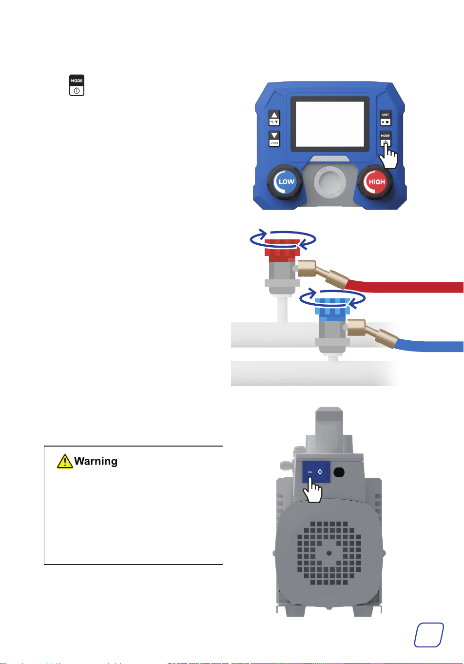
1. Press to switch the gauge to the VAC
mode.
2. Open the service ports of the high-pressure
and low-pressure hoses by turning their
valves clockwise.
3. Turn on the pump by flipping its power
switch to I. You should hear the vacuum
running once it is switched on.
• DO NOT leave the pump
unattended while it is running.
• If you are trying to start the
pump in cold weather, open the
air inlet ports until the pump
reaches normal running speed.
Then, close them.
19
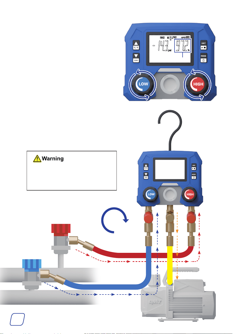
4. Open your gauges by turning their valves
COMPLETELY counterclockwise, and
evacuation will begin. The gauge pressure
will soon drop below 0 and you can check
the vacuum percentage on the right.
5. Wait 30–45 minutes for the vacuum pump
to evacuate the A/C system until the
vacuum percentage reaches 100%.
A small amount of steam from the exhaust
port is normal, as it’s simply condensation
from the A/C system or the vacuum pump.
ALWAYS keep an eye on the
reservoir window during evacuation.
Stop the pump and properly refill the
reservoir if the oil level falls to MIN.
Vacuum Percentage
30-45
mins
20
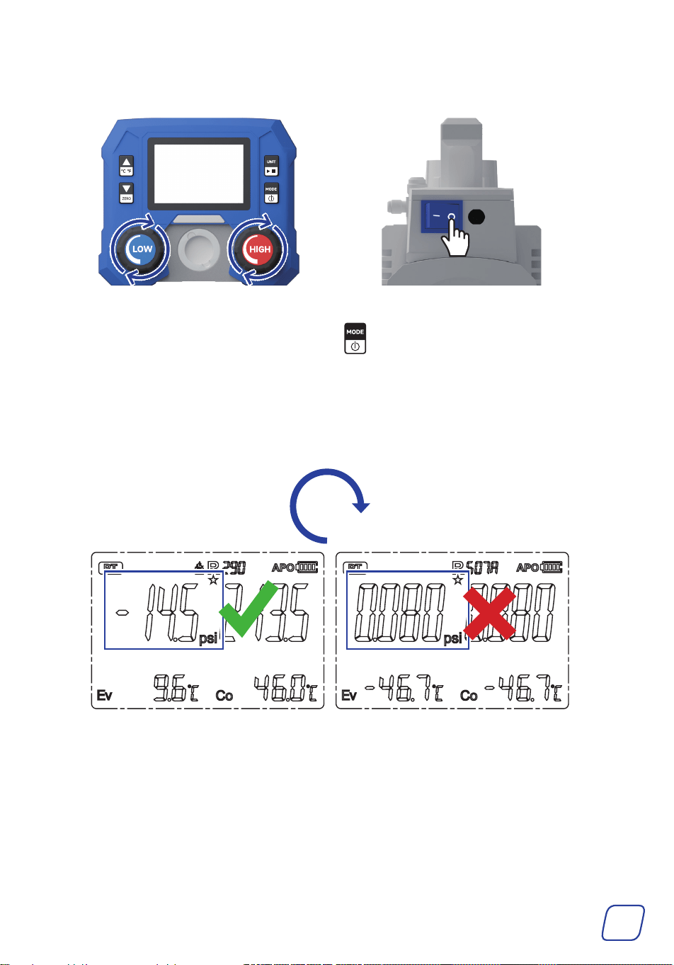
6. Shut off the valves and the vacuum pump by turning the knobs COMPLETELY clockwise and
flipping the pump’s power switch to O.
7. Switch the gauge to the PT mode by pressing . The current pressure should show -1 bar
or -14.5psi.
8. Wait another 30 minutes to confirm there is no leak in the system.
• If the pressures stay the same, there is no leakage and the vacuum is done.
• If the pressures decrease to 0, there is a leakage. Locate and fix the leakage.
30
mins
21
4.3 Charging
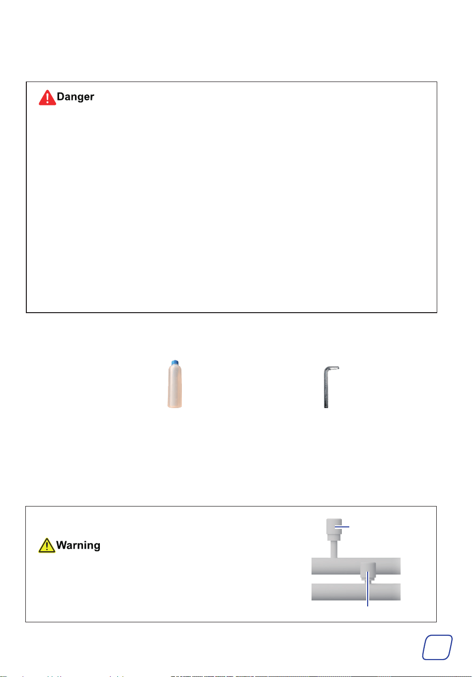
• ALWAYS keep your refrigerant cans away from heat sources and direct sunlight.
• Be cautious NOT to open your refrigerant cans by accident in ANY way.
• Ensure that BOTH gauge valves ARE completely closed BEFORE starting your work.
• NEVER leave your refrigerant cans or the gauge set unattended when charging is ongoing.
• DO NOT overcharge.
Consult your A/C system’s specifications BEFOREHAND to find the recommended
pressure that indicates a full charge, usually between 25 psi (1.7 bar) and 80 psi (5.5 bar).
• NEVER use incompatible refrigerant cans.
• Ensure that the blue LP valve is FULLY closed BEFORE starting your work.
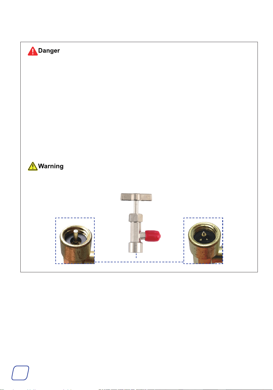
The provided cap lifters ONLY fit cans of SELF-SEALING style. For puncture-style cans,
use cap lifters with taper pins (not included).
PunctureSelf-Sealing
22
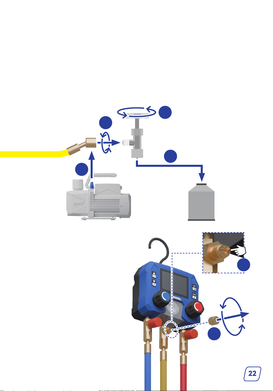
2
3
4
1. Loosen the locking nut and disconnect the yellow hose from the pump.
2. Pull away the protective cap of the R134a cap lifter and connect the cap lifter to the yellow E/C
hose.
If the connection port size does not fit the hose, use adapters K/L to make the connection.
3. Turn the tap handle completely counterclockwise to close it.
4. Securely fit the tap onto your refrigerant can and open the can by turning the handle
completely clockwise.
If your refrigerant does not match the cap lifter, use item K for a secure fit.
1
5. Remove the cap of the valve core.
6. Press the valve core twice to remove air
from the hose.
7. Add the cap back.
5
6
LOW
HIGH
23
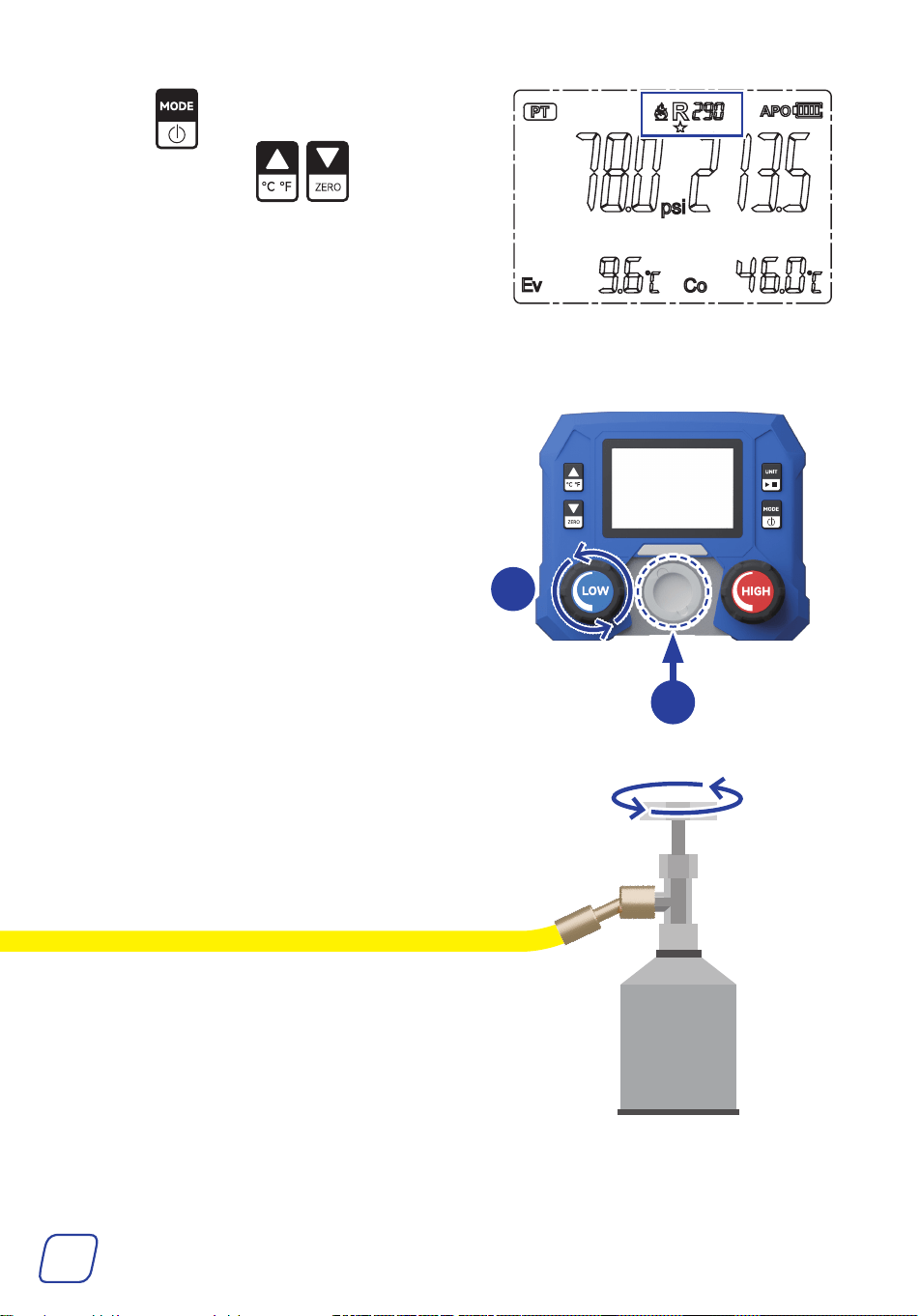
8. Press to switch the gauge to the PT
mode, then press to select the
correct refrigerant.
9. Start your A/C system and set it to the maximum cooling and fan speed.
10. Open the LP valve by turning it completely
counterclockwise. Charging will begin
and you will see the LP gauge’s pressure
changing.
11. Pay attention to the window of the pressure
gauge set.
Ensure that refrigerant is continuously flowing
through and does NOT run out midway.
10
11
12. Once the LP gauge reads the recommended
pressure, turn the handle of the tap
completely counterclockwise to close your
refrigerant can.
24
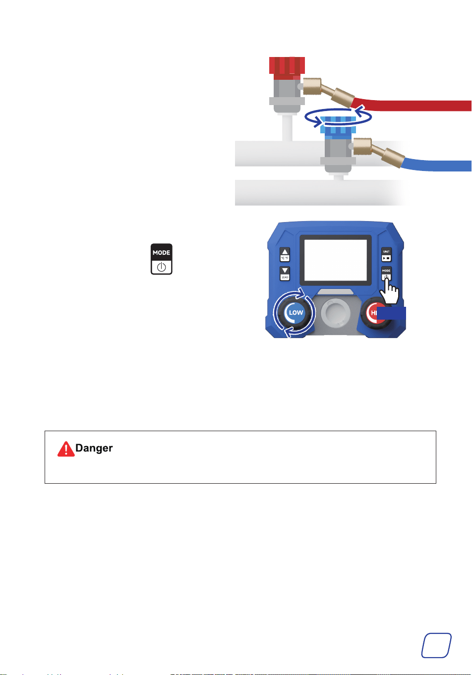
13. Close your system’s LP service port using the
blue LOW coupler.
14. Close the LP valve by turning it
COMPLETELY clockwise. Turn off the
gauge display by holding .
Hold
15. Turn off the A/C system.
16. Remove couplers away from your A/C system by pulling back the coupler sleeves.
Disconnect the three hoses from the tap, quick couplers, and gauge set, then add their caps.
For optimal use, disconnect the pump from power.
Exercise caution WITH any remaining refrigerant that may come out.
25
4.4 Cleaning
• ALWAYS avoid direct pressurized spray.
• DO NOT flush or soak this product.
• NEVER use abrasive or caustic cleaners.
Clear any debris, dust, and oil off the external surfaces of the vacuum pump, pressure gauge set,
hoses, and other items as needed after use.
Recommended Tools:
• Soft dry brush
• Soft damp cloth
• ANSI or OSHA-compliant compressed air
5 Maintenance
5.1 General Maintenance
• ALWAYS disconnect this product from power and A/C systems BEFORE performing
ANY maintenance tasks.
Failure to do so can cause accidents, leading to equipment damage and personal injury.
• For tests or other purposes that require power or system connections to be restored,
wear INSULATED hand protection as well as ANSI or OSHA-compliant breathing and
eye protection.
• Be careful NOT to scrape or abrade the hoses and NOT to drop the pump or gauge set
on hard or rough surfaces.
• Disconnect the pump from power between uses and before performing any cleaning,
maintenance, or repairs.
• Clean the exterior of the pump and the gauge set with a soft damp cloth. DO NOT use harsh
abrasives or caustic chemicals.
• NEVER drop the pump on hard or rough surfaces.
26
• Clear any debris, dust, and oil off the external surfaces of the vacuum pump and other items
as needed after each use. DO NOT allow any electrical component to become wet or damp.
Recommended tools: Soft dry brush, soft damp cloth, ANSI or OSHA-compliant compressed air.
ALWAYS avoid direct pressurized spray. DO NOT flush or soak this product. NEVER use
abrasive or caustic cleaners.
• Check the vacuum pump and other items for any wear, damage, and malfunction after each use.
If any part of the pump is damaged, worn, or shows signs of malfunction, repair or replace it
with a new identical part before further use, especially the filter.
• DO NOT disassemble the pump or gauge set WITHOUT professional training. Repairs to the
internal components should only be done by trained technicians.
• ANY consequences of unauthorized modification WILL void ALL warranties stated or implied.
• If the pump will not be used for an extended period, clean all items, seal all ports with their
protective caps, and store the pump and its accessories in a cool, dry, and clean place away
from flammables, explosives, caustics, and heat sources, and out of children’s reach.
5.2 Replacing Vacuum Pump Oil
Be mindful of the oil behind the reservoir window. If it turns turbid, replace oil as follows.
Tools and Parts Needed
• The provided vacuum pump oil or any other equivalent (ISO 100 or SAE 30)
• M4 hex wrench
1. Make sure the oil remains warm.
Note: If unsure, run the pump for about 10 minutes to heat the oil sufficiently.
Remember to deactivate and unplug the pump BEFORE continuing.
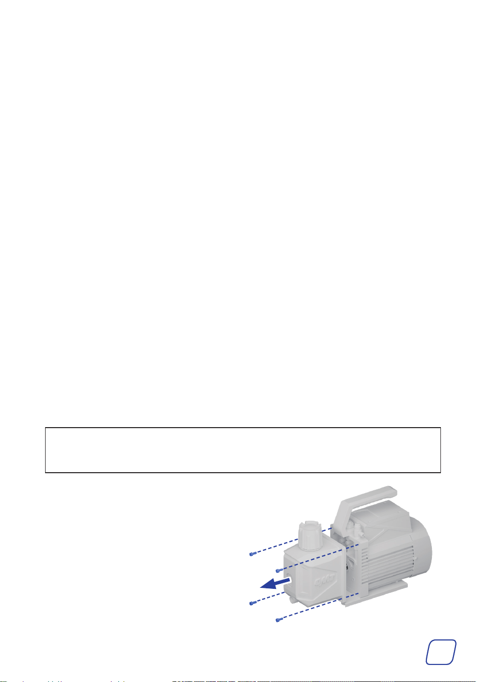
2. Remove the oil tank by removing the four
bolts using a hex wrench.
27
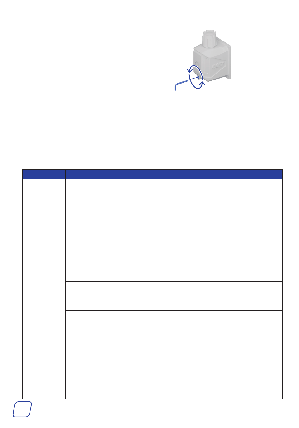
3. Remove the oil drain cap using your M4 hex
wrench.
4. Drain the remaining oil into a suitable container.
5. Refill the tank with new oil until the level is between the MIN and MAX height marks.
6. Add the cap and the oil tank back into place.
6 Troubleshooting
Problems Possible Solutions
Low Vacuum
or leakage
Check if the vacuum itself has leakage.
Remove the connected hose, turn on the pump, and close the gas inlet ports.
• If oil mist continues to escape without any gas entering the pump, it
indicates a leak inside the vacuum pump. Do the following to repair it:
a. Check if the gas inlet port is loose and tighten if so.
b. Check if the rubber ring in the gas inlet port is damaged and replace if
so.
c. Check if the oil inlet port is clean.
• If there is no continuous oil mist, check all connections, such as the
connecting hoses, the container, and if the O-rings on the hoses are missing
or damaged. There could also be a possibility of leaks in the A/C system
itself.
Check if the oil inlet of the pump is blocked or the oil supply is insufficient.
Open the oil tank, clean the pump chamber inlet, and clean the oil inlet and
the filter.
Check if the pump oil is emulsified and unclean. If it is, replace the oil.
Check the size of the vacuumed container, recalculate, and select the
appropriate type of pump.
Check if the gap caused by parts wear is increased. If it is, repair or replace the
pump.
Oil leakage
Check if the connections of the oil tank are loose or damaged. If they are,
retighten all bolts around the oil reservoir and adjust the O-rings.
Check if the pump’s support surface is flat and level.

28
Problems Possible Solutions
Oil Ejection
Check if the oil is over the MAX mark. If it is, discharge oil to the level
between the MIN and MAX height marks.
The inlet pressure is too high for a long time.
Choose the right pump to increase the pumping speed.
The vacuum
pump cannot
turn on or it
automatically
turns off.
The motor temperature is too high.
The thermal protector will deactivate your pump if its motor reaches
160 ° F (70 ° C). Wait about 15 minutes for it to cool down, then restart your
pump.
The oil temperature is too low.
Move the pump to a warmer location and wait a while before reactivating it.
Or, remove the gas inlet cap and the oil filter, and turn the fan blades
counterclockwise with a flat-head screwdriver. After the pump turns on
normally, add the gas inlet cap and the oil filter.
Check if the motor, power supply, or circuit board have problems. If they do,
have them repaired by trained technicians.
Check if some foreign matter dropped into the pump and remove if any.
Check if your power supply is correct and functions well.
Check for damage to the power cable. If necessary, ask your local dealer or
contractor for a new identical replacement.
If there are no issues with your power supply or power cable, securely
reconnect the power cord to the power source and inlet.
The overload protection occurs. If this is the case, keep the switch on, remove
the power cable, wait for about 30 seconds, check and solve why the overload
occurs, and then plug in the power cable.
Oil Backflow
This pump is equipped with an anti-backflow device, but backflow may still
occur in about 5% of cases due to factors such as pressure, impurities, or
obstruction.
After operation, disconnect the vacuum pump from the gauge set or close the
middle valve BEFORE turning off the pump to prevent backflow.
Incompatible
Gauges
Replace with the compatible SAE parts.
Error Codes
E 01: Remove the battery and reinsert it into the gauge. If the error persists,
contact customer service.
E 02: Calibration is required, contact customer service.
E 03: Contact customer service.
E 04: Contact customer service.

Scan for the latest user manual
Rev. 11 Feb. 2025