User Guide
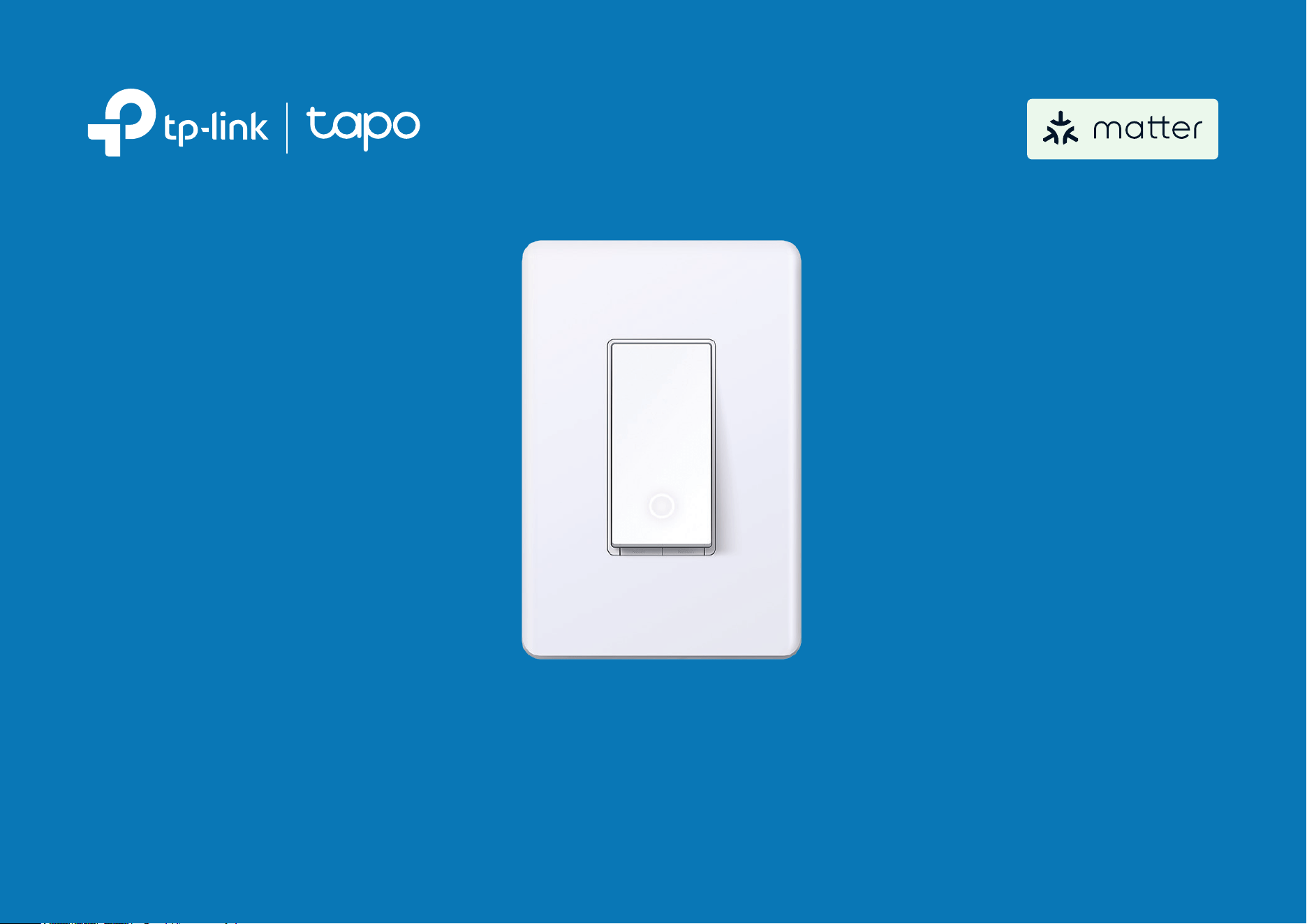
Smart Wi-Fi Light Switch
©2025 TP-Link 1910013857 REV1.0.1

Contents
About This Guide ···········································································1
Introduction ······················································································2
Appearance ······················································································3
Button & LED ···················································································· 4
Set Up Your Switch ·······································································5
Set Up Your Smart Switch via Matter ·································6
Reset Your Smart Switch ···························································9
Authentication ··············································································11
1
About This Guide
This guide provides a brief introduction to the Smart Wi-Fi Light Switch and regulatory information.
Please note that features available in Tapo may vary by model and software version. Tapo availability may also vary by region. All images, steps, and
descriptions in this guide are only examples and may not reect your actual Tapo experience.
Conventions
In this guide, the following convention is used:
Convention Description
Blue
Key information appears in blue, including management page text such as menus, items, buttons and so on.
Underline
Hyperlinks are in blue and underlined. You can click to redirect to a website.
Note:
Ignoring this type of note might result in a malfunction or damage to the device.
More Info
• Specications can be found on the product page at https://www.tapo.com.
• Our Technical Support and troubleshooting information can be found at https://www.tapo.com/support/.
2
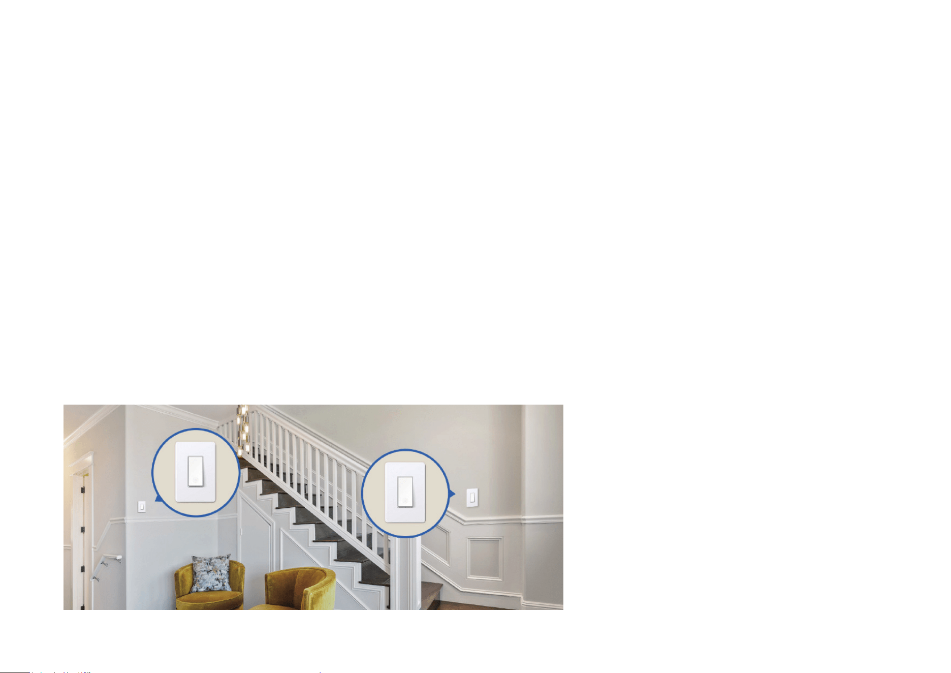
Introduction
With the Tapo Smart Wi-Fi Light Switch, smarten up your traditional lights.
• Schedule – Schedule your lights to turn on/o automatically according to your daily routine and preferences.
• Remote Control – Instantly turn connected devices on/o wherever you are through the Tapo app.
• Auto-O Timer – Automatically turns o a connected device after the device is left on for a set time. No more wasted electricity in unoccupied
areas ever again.
• Away Mode – Away Mode will automatically turn your connected devices, like lights, on and o randomly, to make it appear as if you're home.
• Local Control – Your connected devices at home remain accessible via the Tapo app even when the household goes oine.
• Zero-Crossing Detection – Zero-Crossing Detection addresses relay contact welding, a key issue in smart plug failures. This technology
increases the lifespan of relays by more than 9 times*.
*Based on Tapo’s laboratory results, actual eect may vary depending on working conditions and environments. Mainly suitable for capacitive load
devices, such as lights, TVs, computers, chargers, etc.
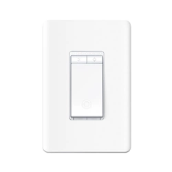
3
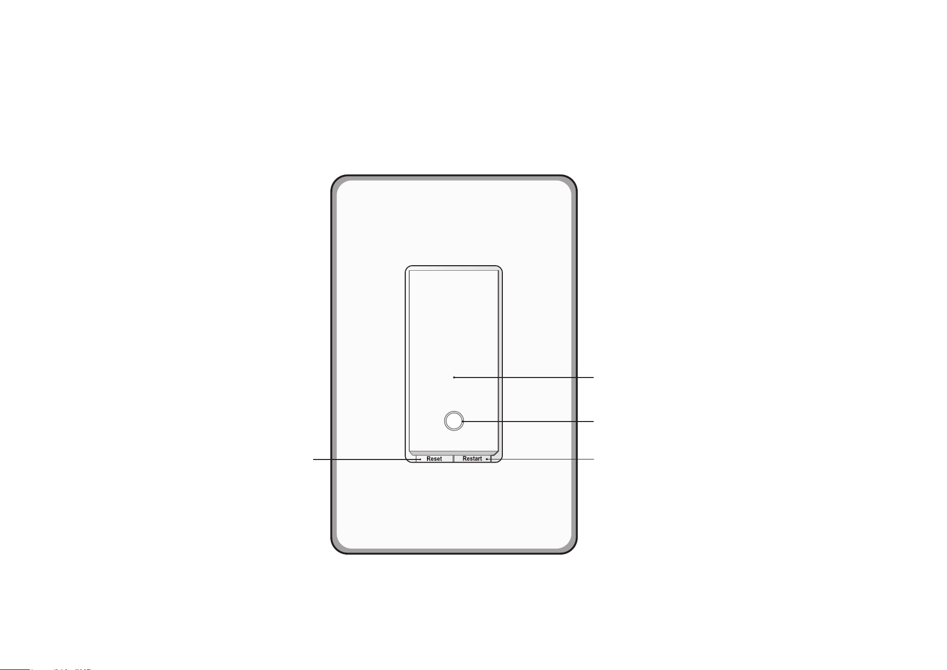
Appearance
Switch
Button
Restart
LED
Reset
4
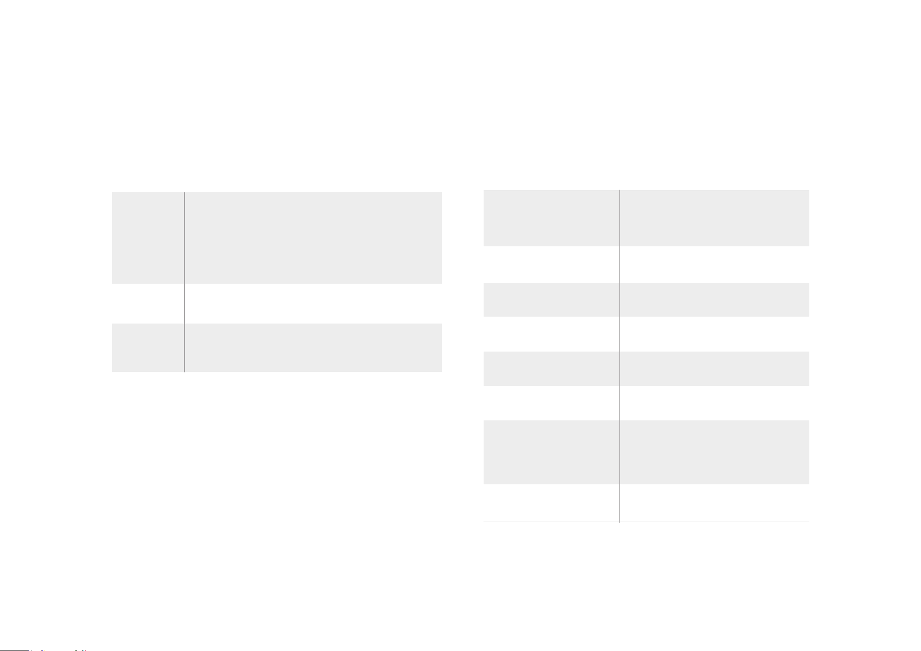
Button & LED
Buttons
Press to turn on / off your switch.
Restart
Reset
Switch
Button
Press and hold for about 5 seconds to reset
Wi-Fi while keeping previous settings.
Press to restart your switch.
Press and hold for about 10 seconds to
restore your switch to factory default settings.
Starting up;
Disconnected from the cloud
Solid amber
Blinking amber
Blinking green
Solid red
Solid green for 30s
Blinking amber & green
Connecting to Wi-Fi
Ready for setup
Device resetting
Solid white
The switch is off.
LED is on to indicate the switch
location in the dark.
Disconnected from Wi-Fi
Connected to Wi-Fi
LED
Blinking green slowly Firmware upgrading
5
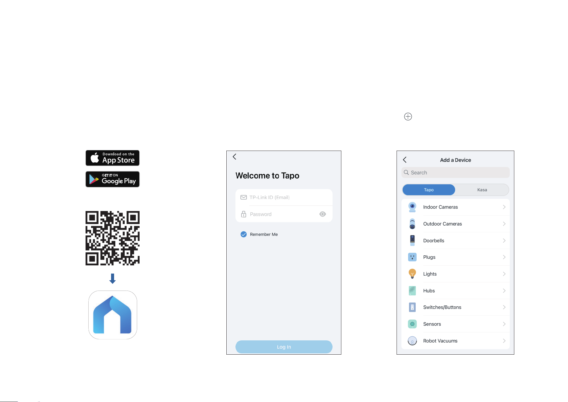
Set Up Your Switch
Follow the steps below to set up your switch.
Step 1. Download Tapo App
Get the Tapo app from the App Store or
Google Play, or by scanning the QR code
below.
OR
Step 2. Log In
Open the app, and log in with your TP-Link ID.
If you don't have an account, create one rst.
Step 3. Add Your Switch
Tap the button in the app. Select Switches/
Buttons and then your model. Or search your
model directly. Then follow app instructions to
set up your switch.
6
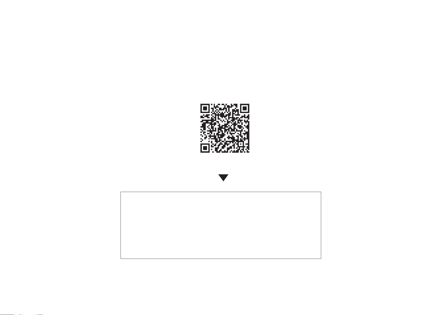
Set Up Your Smart Switch via Matter
Scan QR Code
Visit
https://www.tp-link.com/support/faq/3520/
• Matter setup in dierent ecosystems
• Multi-admin setup and videos
• Features supported in dierent ecosystems
• Troubleshooting & Help

7
Set Up via Matter
This is a Matter-certied device. You can integrate it into any Matter ecosystem you prefer for easy control.
Before You Start
• Factory reset your device before setup.
• A Matter-supported controller and smart home app of the same ecosystem are required. For optimal performance, please update them
to the latest version.
Note: For iOS 18 and above, using a controller is optional. However, with a controller, you can fully enjoy remote control, automation, and
other advanced features.
• The Matter setup code on the device is only applicable for the initial ecosystem. To add it to a new ecosystem, you will need to generate a
new setup code from a smart home app of an already-established ecosystem in your home.
• Take a photo of the Matter setup code for backup.
• Bluetooth will be turned o 15 minutes after the device is powered up. Restart your device to re-enter setup mode.
How to Set Up
*Setup processes may vary between ecosystems.
1. Turn on Bluetooth on your phone.
2. Open the smart home app, then scan the Matter QR code or enter the provided numeric setup code (usually can be found on your
device).
3. Follow the instructions in the app to complete setup.
Failed to Set Up?
• Try to connect your phone to a stable 2.4 GHz Wi-Fi network with internet access instead of a 5 GHz network.
• Restart your device, controller or phone.
• Make sure IPv6 is enabled on your router.
8
Matter is still developing and the progress of each platform may dier from one another. There may also be dierent device performances
and bugs that have no relation to the device itself. TP-Link is working hard to optimize user experience with other CSA members to provide
better services.
We have professional Technical Support and R&D team. If you have any questions, feel free to contact us. Your feedback matters!
Contact us at
www.tapo.com/support
for Technical Support, FAQs, warranty & more
9
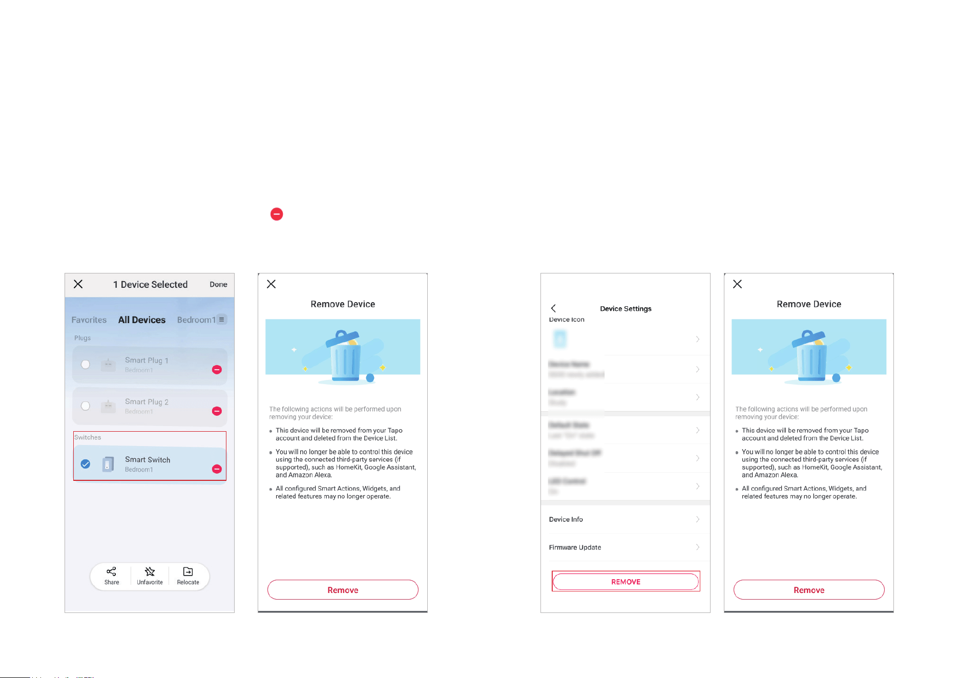
Reset Your Smart Switch
You can remove your device from the Tapo app on the Home page or on the Device Settings page, or by pressing the Reset button on your Smart
Switch.
Home Page
Long press your device and then tap
. Double conrm it.
Device Settings Page
Tap Remove. Double conrm it.
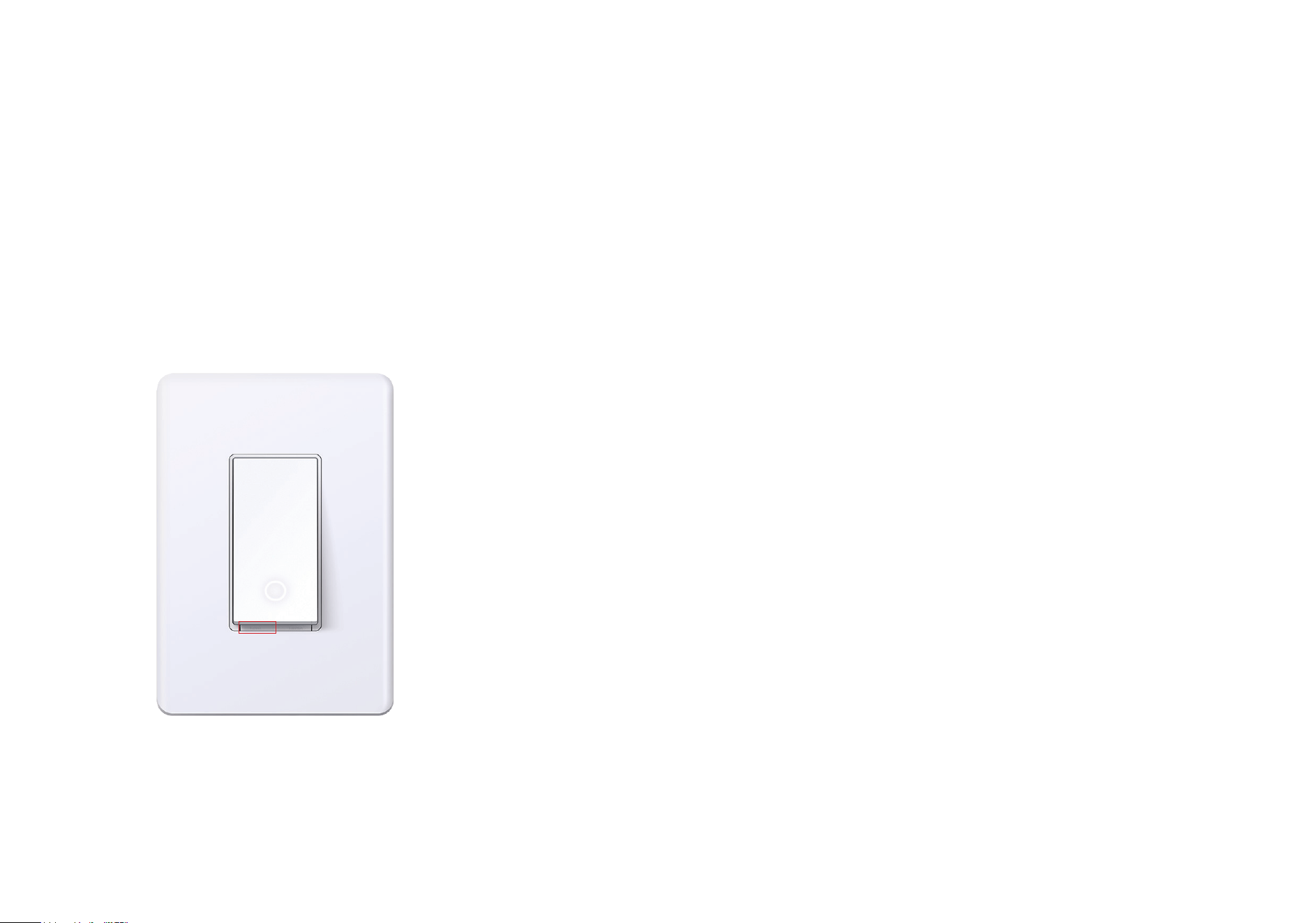
10
Press the Reset button
Press and hold the Reset on the switch for at least 10 seconds to restore factory default settings.
11
Authentication
FCC compliance information statement
Product Name: Tapo Smart Wi-Fi Light Switch
Model Number: Tapo S515
Responsible party:
TP-Link Systems Inc.
Address: 10 Mauchly, Irvine, CA 92618
Website:
http://www.tp-link.com/us/
Tel: +1 626 333 0234
Fax: +1 909 527 6804
E-mail: [email protected]om
This equipment has been tested and found to comply with the limits for a Class B digital device, pursuant to part 15 of the FCC Rules. These limits are
designed to provide reasonable protection against harmful interference in a residential installation. This equipment generates, uses and can radiate
radio frequency energy and, if not installed and used in accordance with the instructions, may cause harmful interference to radio communications.
However, there is no guarantee that interference will not occur in a particular installation. If this equipment does cause harmful interference to radio or
television reception, which can be determined by turning the equipment o and on, the user is encouraged to try to correct the interference by one or
more of the following measures:
• Reorient or relocate the receiving antenna.
• Increase the separation between the equipment and receiver.
• Connect the equipment into an outlet on a circuit dierent from that to which the receiver is connected.
• Consult the dealer or an experienced radio/ TV technician for help.
This device complies with part 15 of the FCC Rules. Operation is subject to the following two conditions:
1. This device may not cause harmful interference.
2. This device must accept any interference received, including interference that may cause undesired operation.

12
Any changes or modifications not expressly approved by the party responsible for compliance could void the user’s authority to operate the
equipment.
Note: The manufacturer is not responsible for any radio or TV interference caused by unauthorized modications to this equipment. Such modications
could void the user’s authority to operate the equipment.
FCC RF Radiation Exposure Statement
This equipment complies with FCC RF radiation exposure limits set forth for an uncontrolled environment. This device and its antenna must not be co-
located or operating in conjunction with any other antenna or transmitter.
“To comply with FCC RF exposure compliance requirements, this grant is applicable to only Mobile Configurations. The antennas used for this
transmitter must be installed to provide a separation distance of at least 20 cm from all persons and must not be co-located or operating in conjunction
with any other antenna or transmitter.”
We, TP-Link Systems Inc., has determined that the equipment shown as above has been shown to comply with the applicable technical standards,
FCC part 15. There is no unauthorized change is made in the equipment and the equipment is properly maintained and operated.
Issue Date: 2024.11.12

13
Canadian Compliance Statement
This device contains licence-exempt transmitter(s)/receiver(s) that comply with Innovation, Science and Economic Development Canada’s licence-
exempt RSS(s). Operation is subject to the following two conditions:
(1) This device may not cause interference.
(2) This device must accept any interference, including interference that may cause undesired operation of the device.
L’émetteur/récepteur exempt de licence contenu dans le présent appareil est conforme aux CNR d’Innovation, Sciences et Développement
économique Canada applicables aux appareils radio exempts de licence. L’exploitation est autorisée aux deux conditions suivantes :
1) L’appareil ne doit pas produire de brouillage;
2) L’appareil doit accepter tout brouillage radioélectrique subi, même si le brouillage est susceptible d’en compromettre le fonctionnement.
Radiation Exposure Statement:
This equipment complies with IC radiation exposure limits set forth for an uncontrolled environment. This equipment should be installed and operated
with minimum distance 20cm between the radiator & your body.
Déclaration d’exposition aux radiations:
Cet équipement est conforme aux limites d’exposition aux rayonnements IC établies pour un environnement non contrôlé. Cet équipement doit être
installé et utilisé avec un minimum de 20 cm de distance entre la source de rayonnement et votre corps
Industry Canada Statement
CAN ICES-3 (B)/NMB-3(B)
Safety Information
Before installing, servicing or removing the switch, read and follow all safety precautions including the following:
• CAUTION – Risk of Electric Shock – More than one disconnect switch may be required to de-energize the equipment and luminaire before servicing.
A circuit breaker which disconnects the Line and Neutral conductor simultaneously is suitable. Ensure power is off at the circuit breaker before
removing or installing any switch. Use a non-contact voltage tester to ensure the power is o.
• The Smart Switch must be installed and used in accordance with the National Electric Code (NEC) or your local electrical code. If you are unfamiliar
with these codes and requirements, or are uncomfortable performing the installation, consult a qualied electrician.
• Do not install the Smart Switch with wet hands or when standing on wet or damp surfaces.
• Tighten terminal screws to 13 lbf-in.
• Keep the device away from water, re, humidity or hot environments.
14
• Do not attempt to disassemble, repair, or modify the device. If you need service, please contact us.
• Do not use the device where wireless devices are not allowed.
• Rating: 100-120 V~ 50
/
60 Hz
• Supported Load: 15 A General Use, 600 W Incandescent, 150W LED
• Operation temperature: 0 ~ 40 °C
• Install only in a suitable UL Listed outlet box or equivalent (suitable dimensions: H > 2.95 in./75 mm, W > 1.81 in./46 mm, D > 2 in./51 mm).
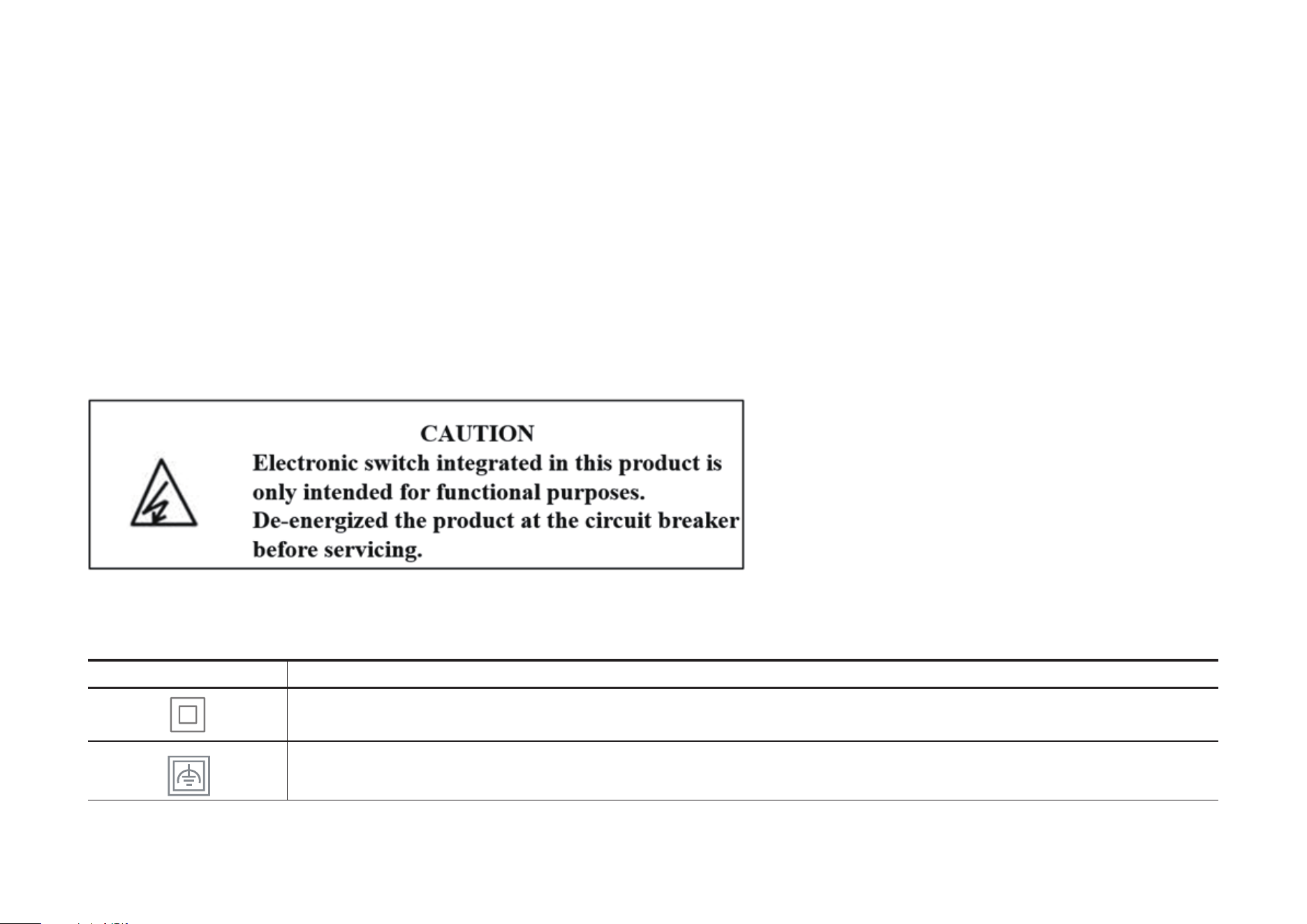
• CAUTION: High Voltage - Disconnect power supply at the circuit breaker before servicing.
• MISE EN GARDE: Haute tension - Déconnectez l'alimentation électrique au niveau du disjoncteur avant toute intervention.
• Method of mounting included: Independently mounted (Vertically position only);
• Operating control, Type 1.C action
• Pollution degree 2, Rated Impulse Voltage 2500V
• Software Class A, NEMA Type 1
Explanation of the symbols on the product label
Symbols may vary from products
Symbol Explanation
Class II equipment
Class II equipment with functional earthing
15
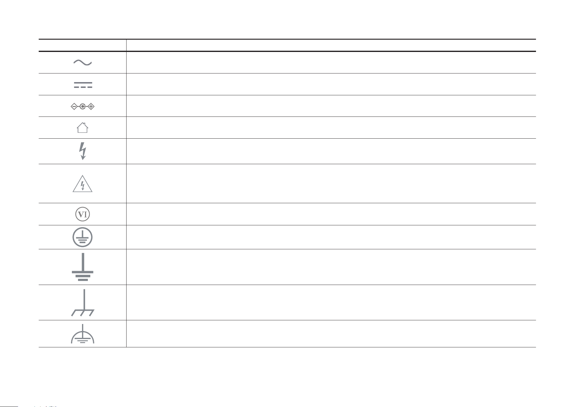
Symbol Explanation
Alternating current
DC voltage
Polarity of output terminals
Indoor use only
Dangerous voltage
Caution, risk of electric shock
Energy eciency Marking
Protective earth
Earth
Frame or chassis
Functional earthing
16
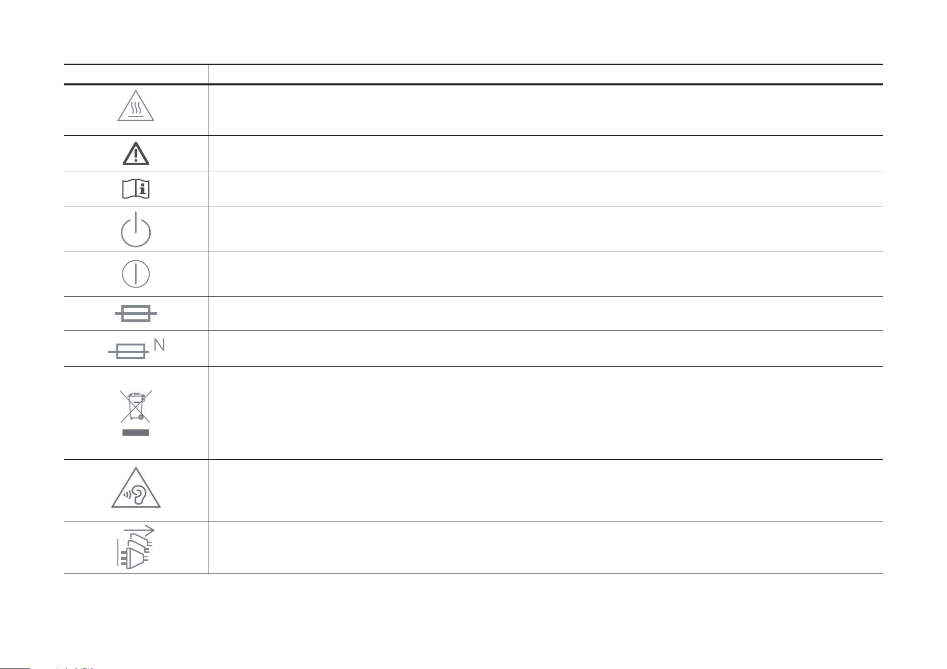
Symbol Explanation
Caution, hot surface
Caution
Operator’s manual
Stand-by
“ON”/”OFF” (push-push)
Fuse
Fuse is used in neutral N
RECYCLING
This product bears the selective sorting symbol for Waste electrical and electronic equipment (WEEE). This means
that this product must be handled pursuant to European directive 2012/19/EU in order to be recycled or dismantled to
minimize its impact on the environment.
User has the choice to give his product to a competent recycling organization or to the retailer when he buys a new
electrical or electronic equipment.
Caution, avoid listening at high volume levels for long periods
Disconnection, all power plugs
17
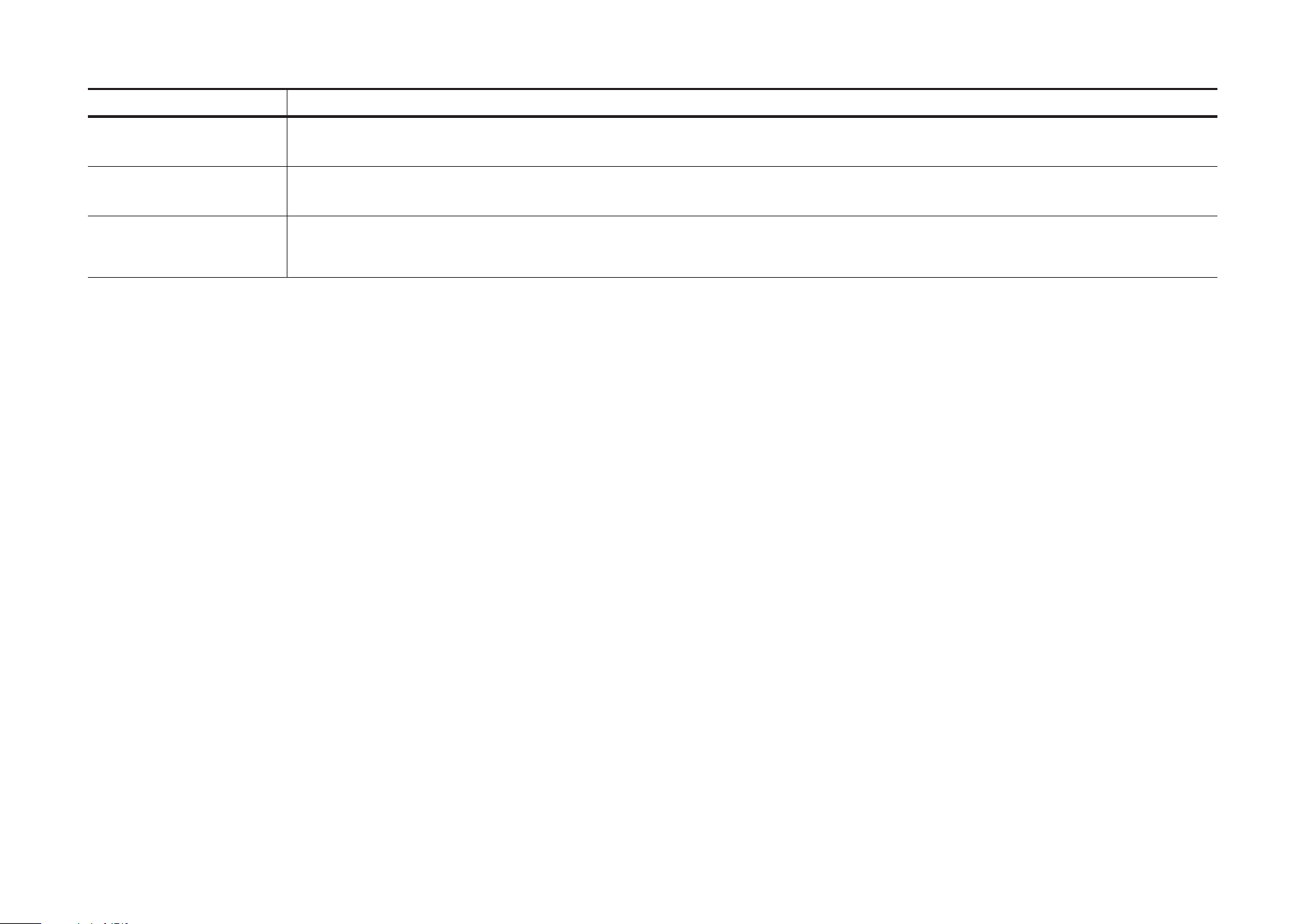
Symbol Explanation
m Switch of mini-gap construction
µ
Switch of micro-gap construction (for US version)
Switch of micro-gap / micro-disconnection construction (for other versions except US)
ε Switch without contact gap (Semiconductor switching device)