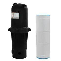
CARTRIDGE FILTER WITH BUILT-IN PUMP
SAVE THIS MANUAL: KEEP THIS MANUAL FOR SAFETY WARNINGS, PRECAUTIONS, ASSEMBLY,
OPERATING, INSPECTION, MAINTENANCE AND CLEANING PROCEDURES. WRITE THE PRODUCT’S
SERIAL NUMBER ON THE BACK OF THE MANUAL NEAR THE ASSEMBLY DIAGRAM (OR MONTH
AND YEAR OF PURCHASE IF PRODUCT HAS NO NUMBER).
OWNER’S MANUAL AND SAFETY INSTRUCTIONS
ITEM #75204
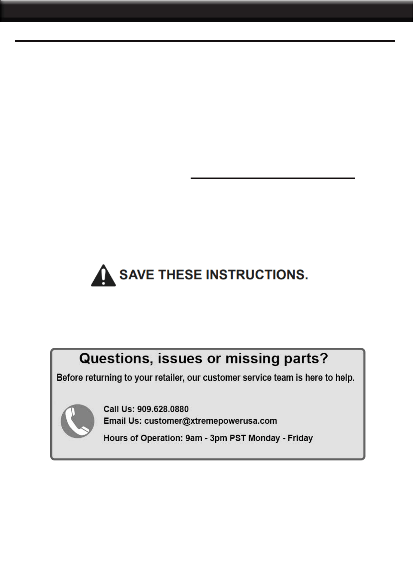
FOR QUESTIONS PLEASE CALL OUR CUSTOMER SUPPORT: (909) 628 0880 MON-FRI 9AM TO 3PM PST

GENERAL SAFETY WARNINGS
1
WARNING -TO REDUCE THE RISK OF INJURY, do not permit children to use this product unless
they are closely supervised at all times.
IMPORTANT SAFETY INFORMATION
Read all safety warnings and instructions. Failure to follow the warnings and instructions may result
in electric shock, re and/or serious injury. Save all warnings and instructions for future reference.
The warnings, precautions, and instructions discussed in this instruction manual cannot cover all possible
conditions and situations that may occur. It must be understood by the operator that common sense and
caution are factors which cannot be built into this product, but must be supplied by the operator. Read
carefully and understand all ASSEMBLY AND OPERATION INSTRUCTIONS before operating. Failure to
follow the safety rules and other basic safety precautions may result in serious personal injury.
CAUTION - To reduce the risk of electric shock the pool must be installed no closer than 6 feet (1.8
m) from any electrical outlet. Do not place portable appliances closer than 5 feet (1.5 m) from the
pool.
DO NOT BURY CORD. Locate cord to minimize abuse from lawn mowers, hedge trimmers, and
other equipment.
WARNING-To reduce the risk of electric shock, replace damaged cord immediately.
WARNING-To reduce the risk of electric shock, do not use extension cord to connect unit to electric
supply; provide a properly located outlet.
CAUTION: This pump is for use with storable pools only. Do not use with permanently-installed
pools. A storable pool is constructed so that it is capable of being readily disassembled for storage
and reassembled to its original integrity. A permanently-installed pool is constructed in or on the
ground or in a building such that it cannot be readily disassembled for storage. Please examine
and verify all sand lter components are present before use. Notify XTREMEPOWERUS at the
customer service number listed on this manual for any damaged or missing parts at the time of
purchase.
SAVE THESE WARNINGS
FOR USE WITH SWIMMING POOLS ONLY.
CAUTION: TO ENSURE CONTINUED PROTECTION AGAINST SHOCK HAZARD, USE ONLY
IDENTICAL REPLACEMENT PARTS WHEN SERVICING.
WARNING: RISK OF ELECTRIC SHOCK. CONNECT ONLY TO A GROUNDING TYPE RECEPTACLE.
CAUTION: FOR CONTINUED PROTECTION AGAINST POSSIBLE ELECTRIC SHOCK THIS UNIT IS
TO BE MOUNTED TO THE BASE IN ACCORDANCE WITH THE INSTALLATION.
1) Connect Only To Properly Grounded Outlet. Do Not Remove Ground Pin.
2) Inspect Cord Before Using – Do Not Use If Cord Is Damaged.
3) Do Not Touch Plug With Wet Hands
4) Double Insulated – When Servicing Use Only Identical Replacement Parts.
2
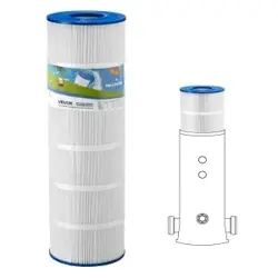
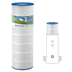
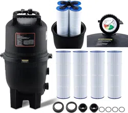
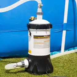
PRODUCT INFORMATION
3
INSTALLATION
FILTER LOCATION
It is important to rst determine where your pump and lter will be located. If above the water line.a self-
priming pump must be used. Self-priming pumps have the ability to lift water from a lower level and prime
automatically.
1. Since plumbing ttings offer a resistance to water ow, position the lter as close to the swimming pool
as local codes allow. Keep the number of ttings to a minimum. Select a well drained area, one that will not
ood when it rains.
2. Set the lter on a solid , level surface. Be sure lter, pump, drain and pressure gauge are accessible for
convenient operation.
3. Position the lter so the tank can drain by gravity.
4. lf practical.place pump and lter in the shade to shield it from continuous.direct heat from the sun
PLUMBING
1. Use 1-1/2” or 2”piping. When making permanent connections, be sure to provide unions for easy servicing.
2. Refer to the diagrams for basic suggested valving. Ballvalves are recommended where needed. While all
systems vary, lrle main consideration is to provide the desired control of water ow from the pool to the pump
and lter, and back to the pool. When the lter IS located below water level, provide valves to prevent back
ow of water to the lter during cleaning and routine servicing.
3. All plumbing on the Star-Clear Plus lter are 1-1/2” or 2”N.P.T. or socket (solvent weld). When making
threaded connections to the lter use plastic adapters. Apply three turns of Teon tape (or use special plastic
pipe sealant) to male threads. Screw the tting into the thread hand tight: then using a wrench, tighten one
more full turn. Additional tightening is unnecessary.
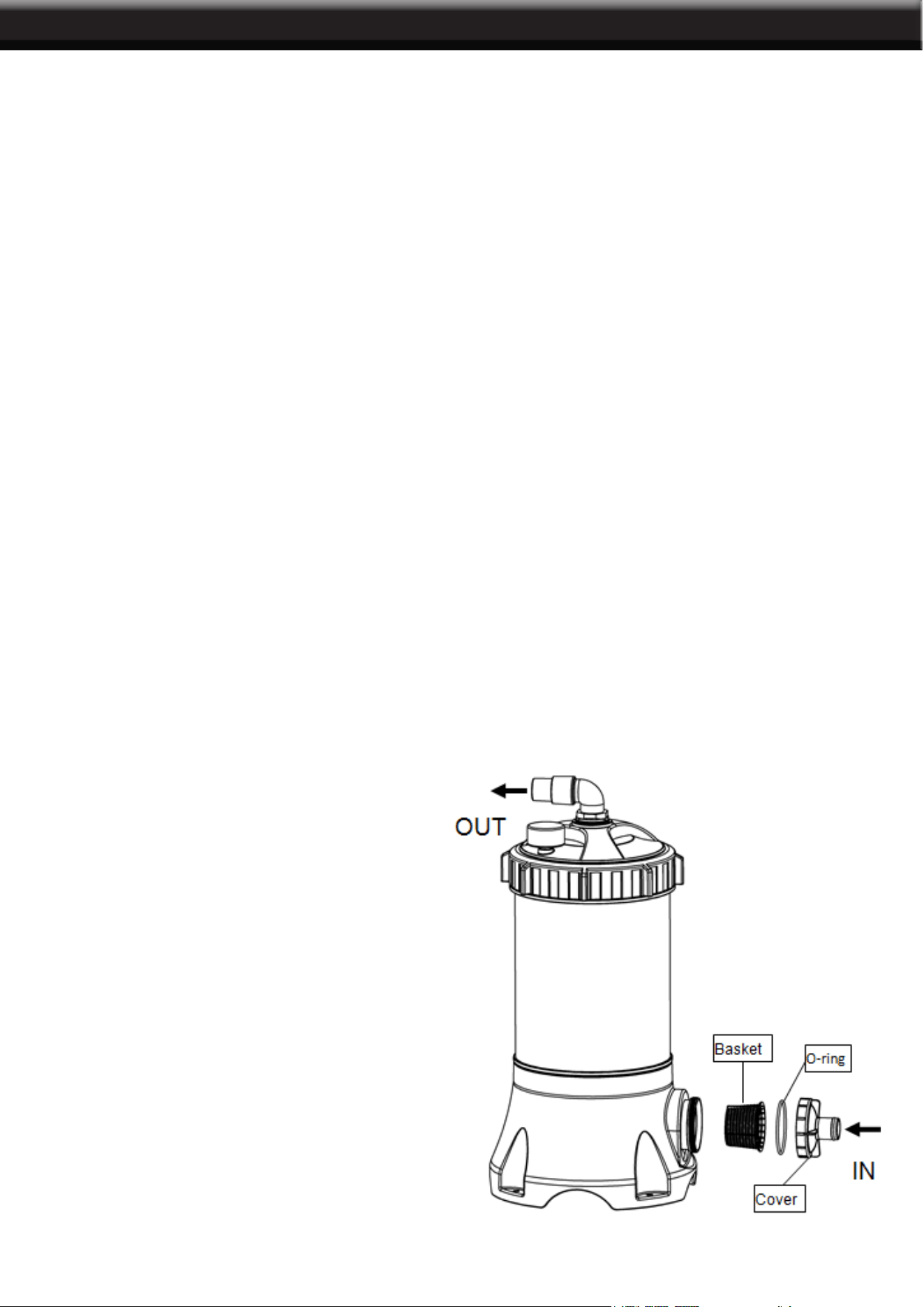
4. Install pre-lter, o-ring and clear cover on the inlet as below illustration.
5. Connect the pool suction plumbing between
the skimmer, pool outlet, etc. and the pump.
6. Install the pool return plumbing.
7. If pressure gauge IS not Installed, apply
Teon tape to the gauge threads, and
carefully screw the gauge into the threaded
hole in the lter head.
8. A manual air relief valve is
furnished to aid in bleeding off unwanted
air when starting the lter. The auto air relief
provides air removal during operation.
9. All electrical connections should be made
In accordance with local codes.
10. Check for joint leaks before operating.
11. Refer to pump instruction booklet for
pump information.
4
OPERATION
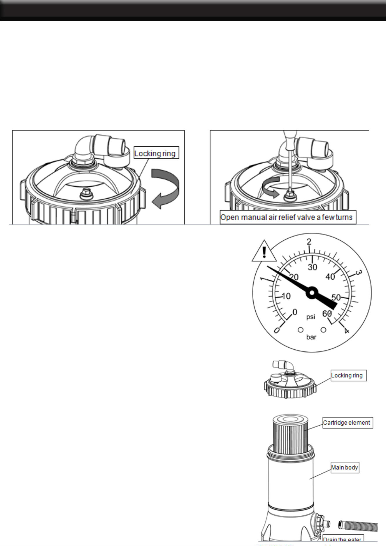
Be sure Locking ring is secure (hand tighten--only slight pressure is required).
1. Open manual air relief valve a few turns
2. All suction and discharge valves must be open when starting the system. Failure to do so could cause
severe personal injury and/or property damage.
3. Stand
clear of the lter and prime and start the pump, following the manufacturer’s instructions. Air trapped
in the system will automatically vent to the pool and out air relief valve. Close air relief valve as soon as air
is vented.
4. Check if the water is running and return to pool, and check the reading of pressure gauge.
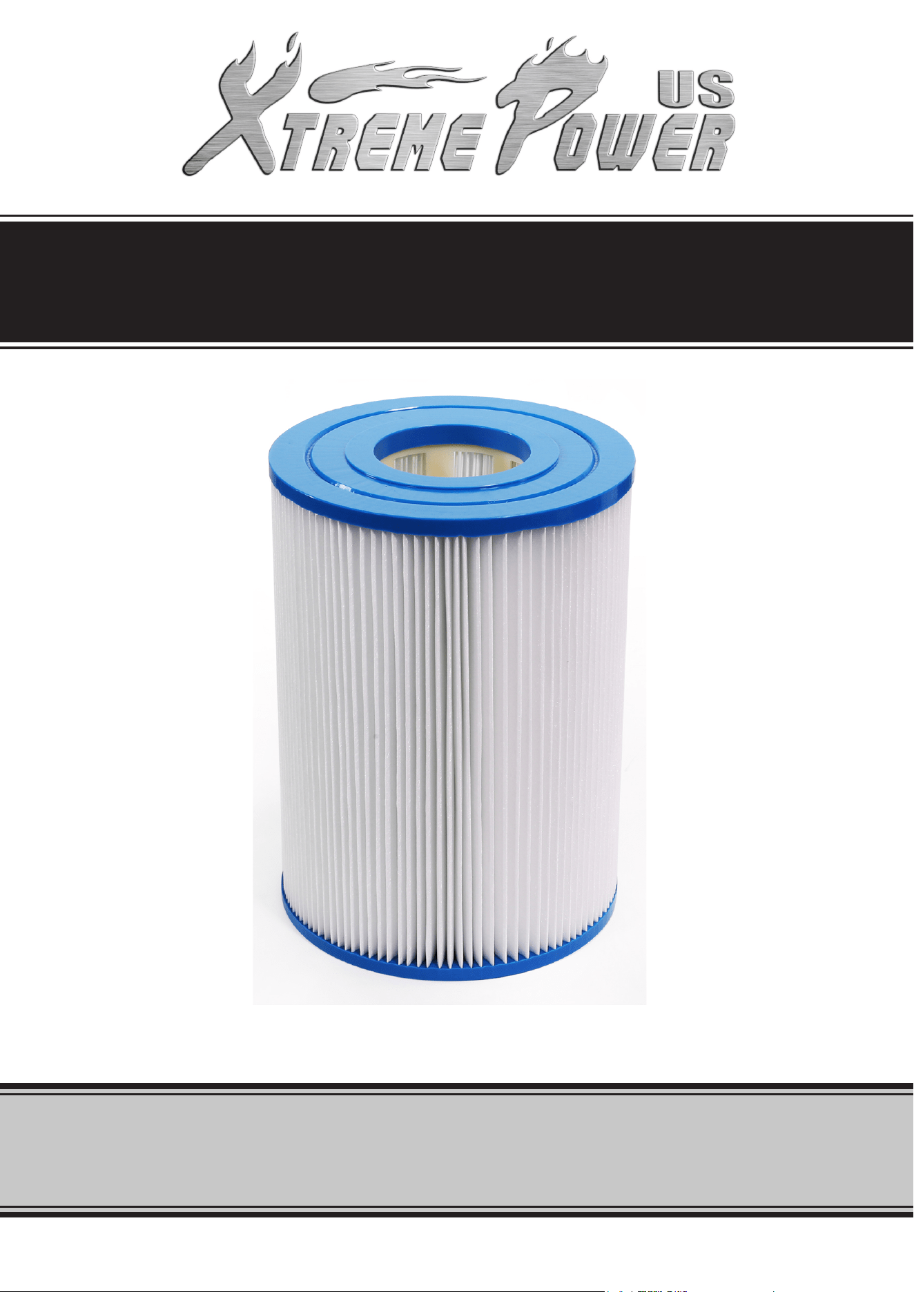
CLEAN/REPLACE CARTRIDGE
Filtration starts as soon as ow is steady through the lter.
As the lter cartridge removes dirt from the pool water, the
accumulated dirt causes a resistance to ow. As a result,
the gauge pressure will rise and the ow will decrease.
When the pressure rises 7-10 psi (.49-.70 Bar) above the
starting pressure, or when ow decreases below desired
rate, clean or replace the lter cartridge.
STARTING THE FILTER
FILTERING
1. Turn off all system circulation pumps and all electric
power on the equipment pad.
2. Set all system valves in a position to prevent water ow
to the lter.
3. Unfasten the clamp on the inlet, take off the hose, drain
the water.
(Note: To assist draining process: open air vent a few turns.)
4. Unscrew and remove locking ring (counterclock wise
direction).
5. Carefully lift off top cover to gain access to lter cartridge.
6. Lift out cartridge and clean. Or, replace with clean, spare
cartridge. (See Cleaning Cartridge.)
5
OPERATION / TROUBLESHOOTING
The cartridge lter element can be cleaned by pressure washing inside and out with a garden hose. (The
cartridge is easier to clean when dry.) After hosing the cartridge, for best results, allow cartridge to dry and
carefully brush pleated surface areas to remove ne particles.
Algae, suntan oil and body oils can form a coating on the cartridge pleats which may not be thoroughly
removed by hosing. To remove such materials, soak the cartridge in a solution of lter element cleaner
(various brands available at pool dealer). Follow manufacturer’s directions for use and allow an hour for
soaking. Hose thoroughly before reinstalling in lter.
If calcium or mineral deposits are excessive, the cartridge may be restored to “like new” condition by soaking
in muriatic acid. Use commercially available 20% muriatic acid added to water in 1 to 1 ratio. Use a plastic
container and take extreme care when handling cleaning agents as they can be harmful to eyes. skin and
clothing. After cleaning, ush with water.
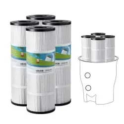
A spare cartridge lter element is an excellent investment. It provides convenience and ensures that your
lter will always be ready to operate at peak efciency.
CLEANING CARTRIDGE
1.Clean any collected debris from the bottom of lter body.
2.Carefully replace cartridge element over tie rod and into lter
body ensuring that the cartridge sits evenly on the collector hub
in bottom of lter body.
3.Tighten locking ring in clockwise direction. (Hand tight only.)
4. Connect the hose to inlet and fasten the clamp.
5. Proceed as in STARTING THE FILTER.
RE-INSTALLATION
In areas where sub-freezing
temperatures can be expected.
the lter should be drained and/or
removed from its operating location
and stored indoors. Remove and
clean cartridge. Reinstall cartridge in
lter tank. Tighten locking knob only a
few turns when storing
WINTERIZING THE FILTER
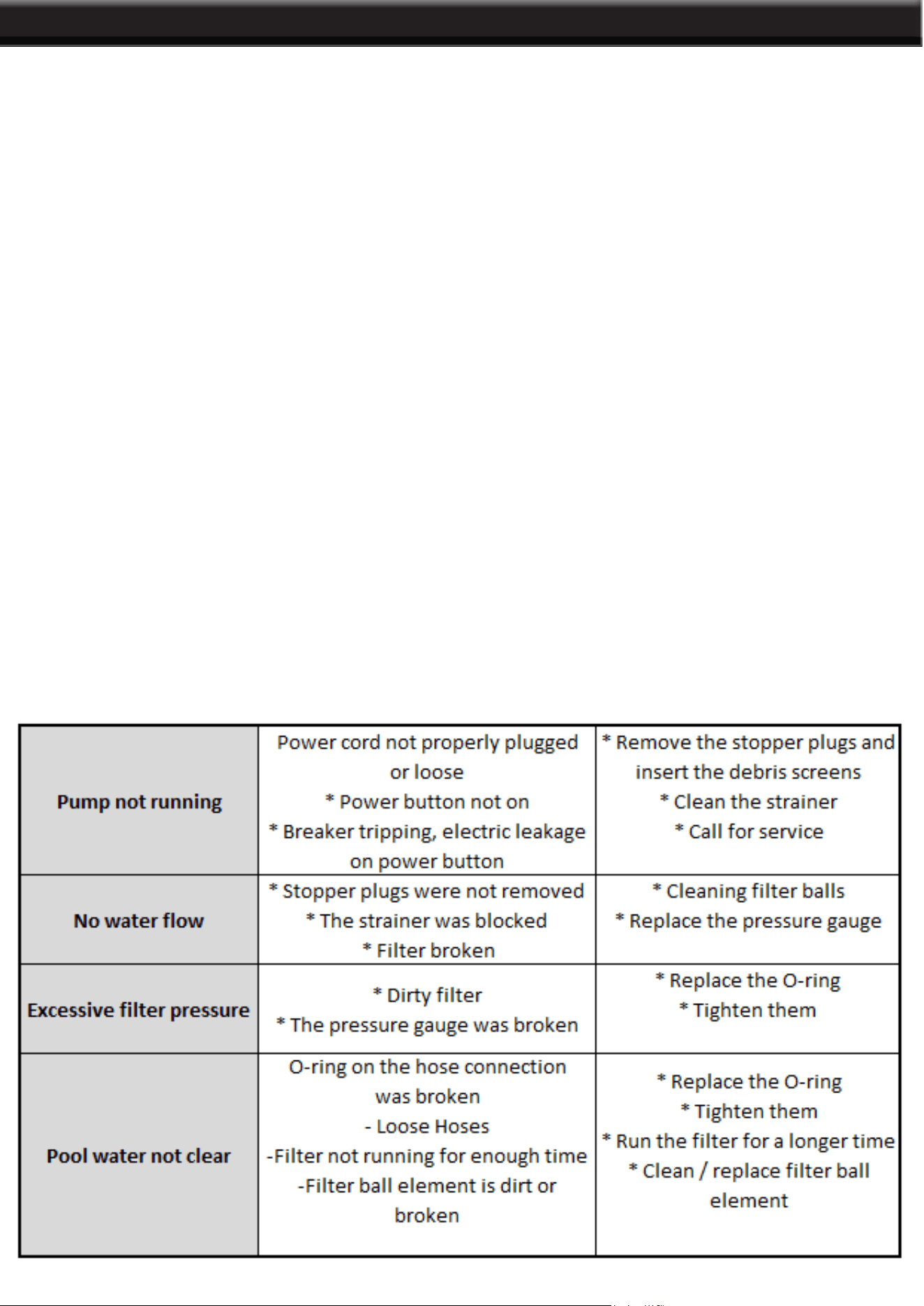
TROUBLESHOOTING
PLEASE READ THE FOLLOWING CAREFULLY
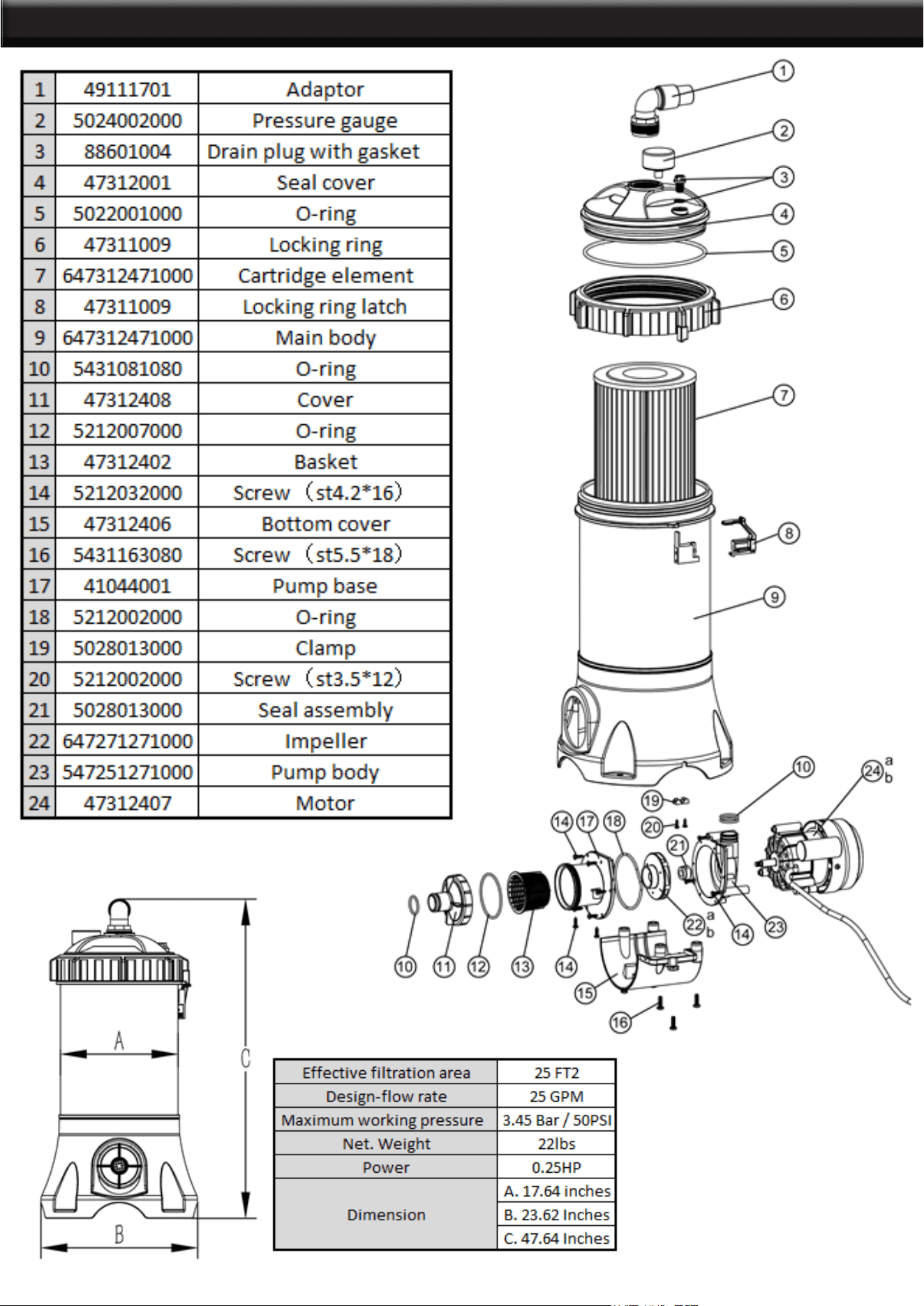
THE MANUFACTURER AND/OR DISTRIBUTOR HAS PROVIDED THE PARTS LIST AND ASSEMBLY
DIAGRAM IN THIS MANUAL AS A REFERENCE TOOL ONLY. NEITHER THE MANUFACTURER OR
DISTRIBUTOR MAKES ANY REPRESENTATION OR WARRANTY OF ANY KIND TO THE BUYER
THAT HE OR SHE IS QUALIFIED TO MAKE ANY REPAIRS TO THE PRODUCT, OR THAT HE OR
SHE IS QUALIFIED TO REPLACE ANY PARTS OF THE PRODUCT. IN FACT, THE MANUFACTURER
AND/OR DISTRIBUTOR EXPRESSLY STATES THAT ALL REPAIRS AND PARTS REPLACEMENTS
SHOULD BE UNDERTAKEN BY CERTIFIED AND LICENSED TECHNICIANS, AND NOT BY THE
BUYER. THE BUYER ASSUMES ALL RISK AND LIABILITY ARISING OUT OF HIS OR HER REPAIRS
TO THE ORIGINAL PRODUCT OR REPLACEMENT PARTS THERETO, OR ARISING OUT OF HIS OR
HER INSTALLATION OF REPLACEMENT PARTS THERETO.
Note: Some parts are listed and shown for illustration purposes only and are not available
individually as replacement parts.
Record Product’s Serial Number Here:
Note: If product has no serial number, record month and year of purchase instead.
6
DISCLAIMER
PRODUCT MADE IN CHINA
WINTERIZING THE FILTER