
Technical Support and E-Warranty Certificate www.vevor.com/support
CARTRIDGE POOL FILTER USER MANUAL
We continue to be committed to provide you tools with competitive price.
"Save Half", "Half Price" or any other similar expressions used by us only represents an
estimate of savings you might benefit from buying certain tools with us compared to the major
top brands and does not necessarily mean to cover all categories of tools offered by us. You
are kindly reminded to verify carefully when you are placing an order with us if you are
actually saving half in comparison with the top major brands.

1
Model: GL320, GL420, GL520
Have product questions? Need technical support? Please feel free to
contact us:
Technical Support and E-Warranty Certificate
www.vevor.com/support
NEED HELP? CONTACT US!
This is the original instruction, please read all manual instructions
carefully before operating. VEVOR reserves a clear interpretation of our
user manual. The appearance of the product shall be subject to the
product you received. Please forgive us that we won't inform you again if
there are any technology or software updates on our product.
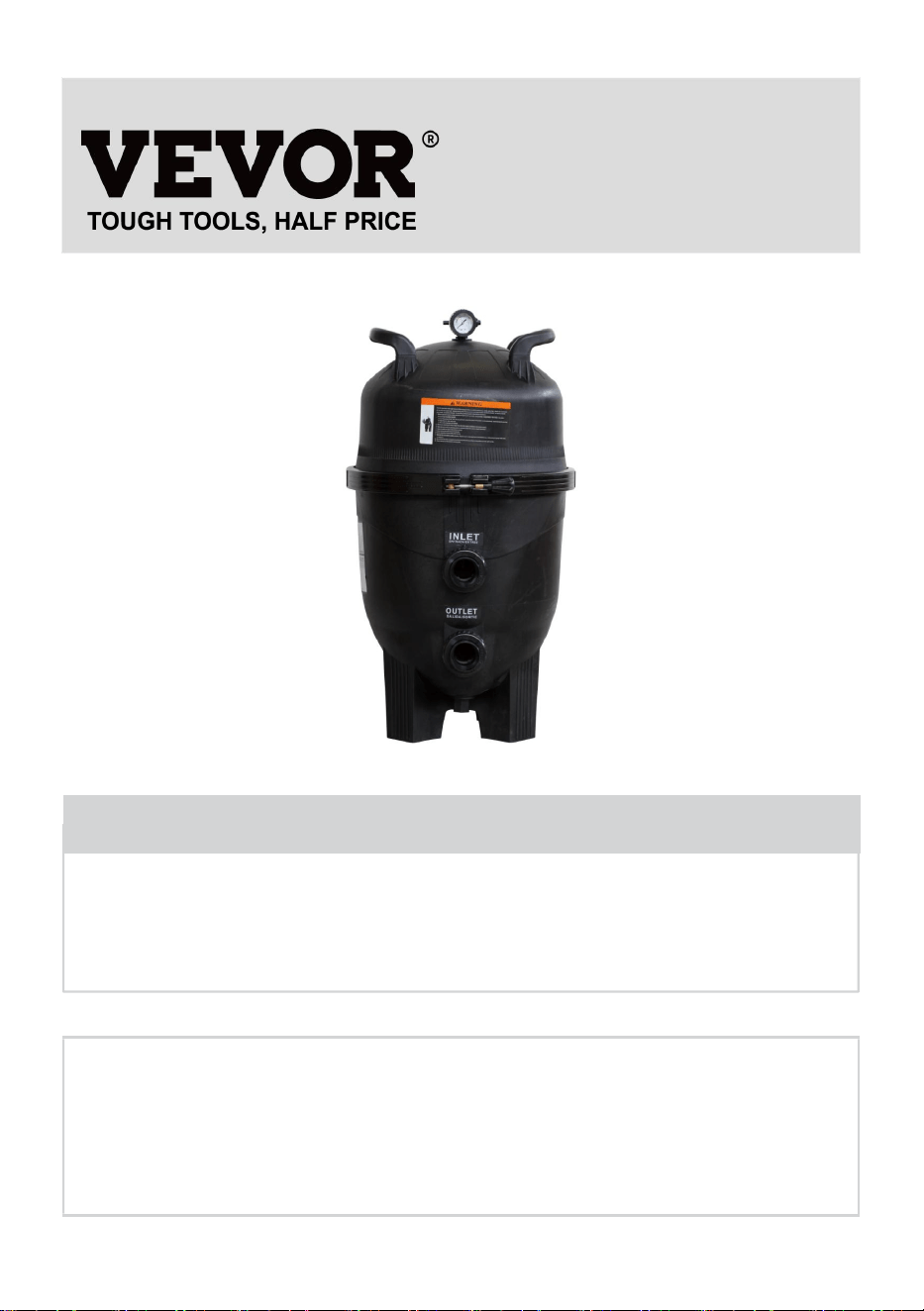
CARTRIDGE POOL
FILTER

2
The installation of this product should be carried out by a person
knowledgeable in swimming pool plumbing requirements, following the
installation instructions provided in this manual. Please pass these instructions
on to the owner of this equipment.
CARTRIDGE FILTER
Congratulations on your purchase of a quality product from the range of pool
and spa equipment available from pool systems. You are assured of many
years of reliable and efficient performance.
Cartridge filters have been specifically designed for the filtration of spa and
swimming pool water. They should not be used for any other purpose without
first consulting your dealer or pool systems.
Cartridge filters provide economy, high performance and convenience in a
well-designed pressure filter. The polyester element can be removed quickly
for rinse cleaning without water loss.
Cartridge filters feature large filter areas, which Ensure even water distribution,
peak filtration performance and longer filter cycles. The corrosion-resistant
construction of cartridge filters provides long life and durability.
Cartridge filters are capacity matched with the range of pool and spa pumps
available from pool systems, forming a total pool filtration system built to last.
Take care to match the pump and filter capacities to gain maximum
performance and efficiency.
CARTRIDGE FILTRATION PROCESS
Cartridge filtration is an effective trouble-free proven method of filtration. Pool
water enters the filter and passes through a polyester single element cartridge.
Suspended particles are trapped and the water is returned to the pool. As the
build-up of dirt in the element increases, so the water pressure rises and the
flow decreases. When the pressure reaches an unacceptable level, the
element must be removed and cleaned(spray washing with a common garden
hose is generally sufficient)

3
INSTALLATION AND OPERATION INSTRUCTIONS
LOCATION
The filter should be placed in its permanent location, preferably as close to the
pool or spa as practicable. Position the filter tank and pump on a level concrete
slab or similar base. Allow sufficient space around the filter for routine
maintenance and provide for adequate ventilation and drainage. Place the
pump in position on the slab and locate the filter alongside the appropriate
pump inlet connection orientated towards the pump. Refer to the
'Specifications' section for the minimum clearance measurements required for
each model.
WEATHER PROTECTION
Cartridge filters are constructed of corrosion-resistant materials. However, to
ensure years of reliable performance, it is recommended that the filtration
system be adequately protected from the weather.
ASSEMBLY
Assemble the pressure gauge to the filter lid using Teflon tape on the male
thread. Do not over-tighten.
PIPE CONNECTIONS
Piping should be supported independently and not impose heavy loads on the
filter or pump. Use 40mm or 50mm PVC pipe for pump and pool return lines.
50mm should always be used if length of piping is over 15mm. Cartridge filters
are supplied with quick connect couplings suitable for 40mm L.D.PVC pipe or
50mm O.D fittings.if the pump and filter are located below pool water level, it is
necessary to fit isolating valves in the pipe between the pump and the pool,
and in the return line from the filter to the pool.
1) Pump to filter

4
Cartridge filters are equipped with two inlet ports marked 'INLET'. Select the
inlet port most suitable for the installation and plug the other inlet port with
blanking cap provided. Using quick connect couplings, connect the pool pump
delivery piping to the selected inlet port couplings, connect the pool pump
delivery piping to the selected inlet port. Tighten by hand only. Ensure the
o'ring lubricant and in the correct position.
2) Filter to pool return
Using quick connect couplings, connect the pool return piping to the filter fitting
marked 'OUTLET'. Tighten the fitting by hand only. Ensure the o'ring on the
fitting is clean, lubricated with o'ring lubricant and in the correct position. The
filter base is provided with four mounting holes to enable it to be secured, if
required.
FILTER OPERATION
1) Make sure the pump is primed according to manufacture's directions.
2) Be sure all valves are open on suction and discharge lines. Ensure the air
bleed valve on the filter lid is open and the lid lock ring is in place and secure.
3) Start the pump. Close the air bleed valve when water is expelled.
4) To determine the correct operating conditions with a clean filter, check that
the pressure gauge reading is 180kpa or below.
5) Record the pressure gauge reading or mark the needle position on the
face of the pressure gauge.
6) Operate the filter for a sufficient time to circulate the total pool water volume
daily. The filter should also be operated at all times the pool is in use and for
about one hour afterward. During winter, the running time may be reduced.
Filter operating requirements will vary for spa applications. Depending on the
system design, type, and size of the spa. Consult your builder or spa supplier.
7) When the pressure gauge reading is 180-230kpa higher than the 'clean
filter' reading as in (4) above, it is time to clean the cartridge element(see'
Cartridge Cleaning Procedure).

5
CARTRIDGE CLEANING PROCEDURE
When the filter gauge reading is 50-70kpa above the clean filter gauge reading
cleaning the single element cartridge is required. To perform the cleaning
procedures
1) Switch off the pump.
2) Close isolating valves on suction and discharge lines where fitted.
3) Open the air bleed valve on the filter lid. unscrew the lock ring and remove
the filter lid.
4) Lift out the cartridge element.
5) In most cases the element can be easily cleaned with a garden hose, using
good velocity sprayed directly on the pleats.
NOTE
Algae, calcium, clay, suntan oil and body oils can form a coating on the
element which may not be easily removed with normal hosing. These
materials can be removed by soaking the element in a de-greaser and / or
descaler. Your local dealer will be able to recommend suitable products.
CARTRIDGE RE-ASSEMBLY INSTRUCTION
1) Install the cartridge/s and center pipe so that it is located in the bottom
spigot.
2) Ensure the filter lid o'ring is clean, lubricated with o'ring lubricant and
located in the bottom groove.
3) Replace the lid and press firmly in place. Screw down the lock ring, hand
tight is sufficient-DO NOT OVER TIGHTEN.
4) Make sure the pump is primed according to manufacture's directions.
5) Ensure all valves are open on suction and discharge lines.
6) Start the pump.
7) Close the air bleed valve when all air has been expelled.
6
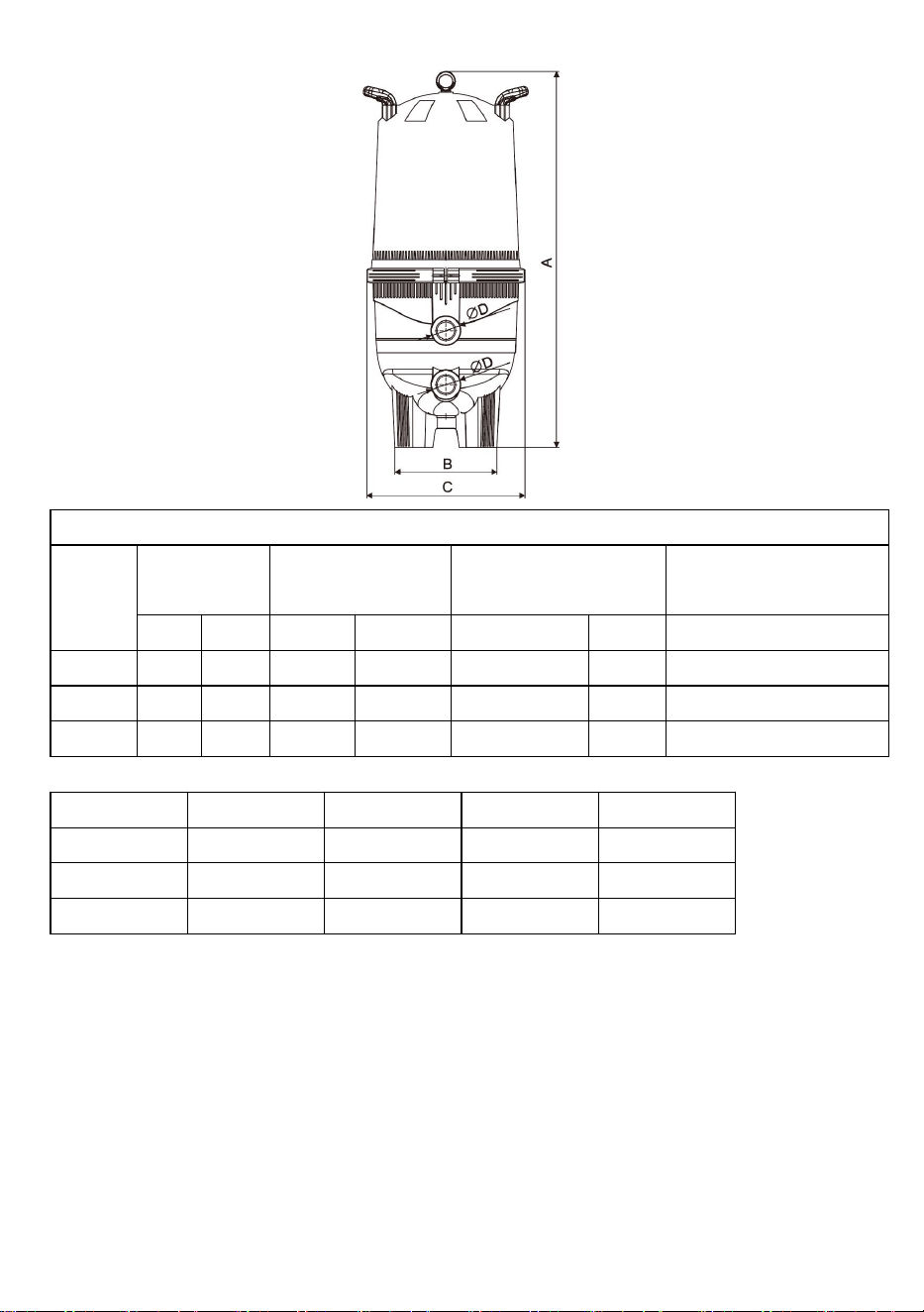
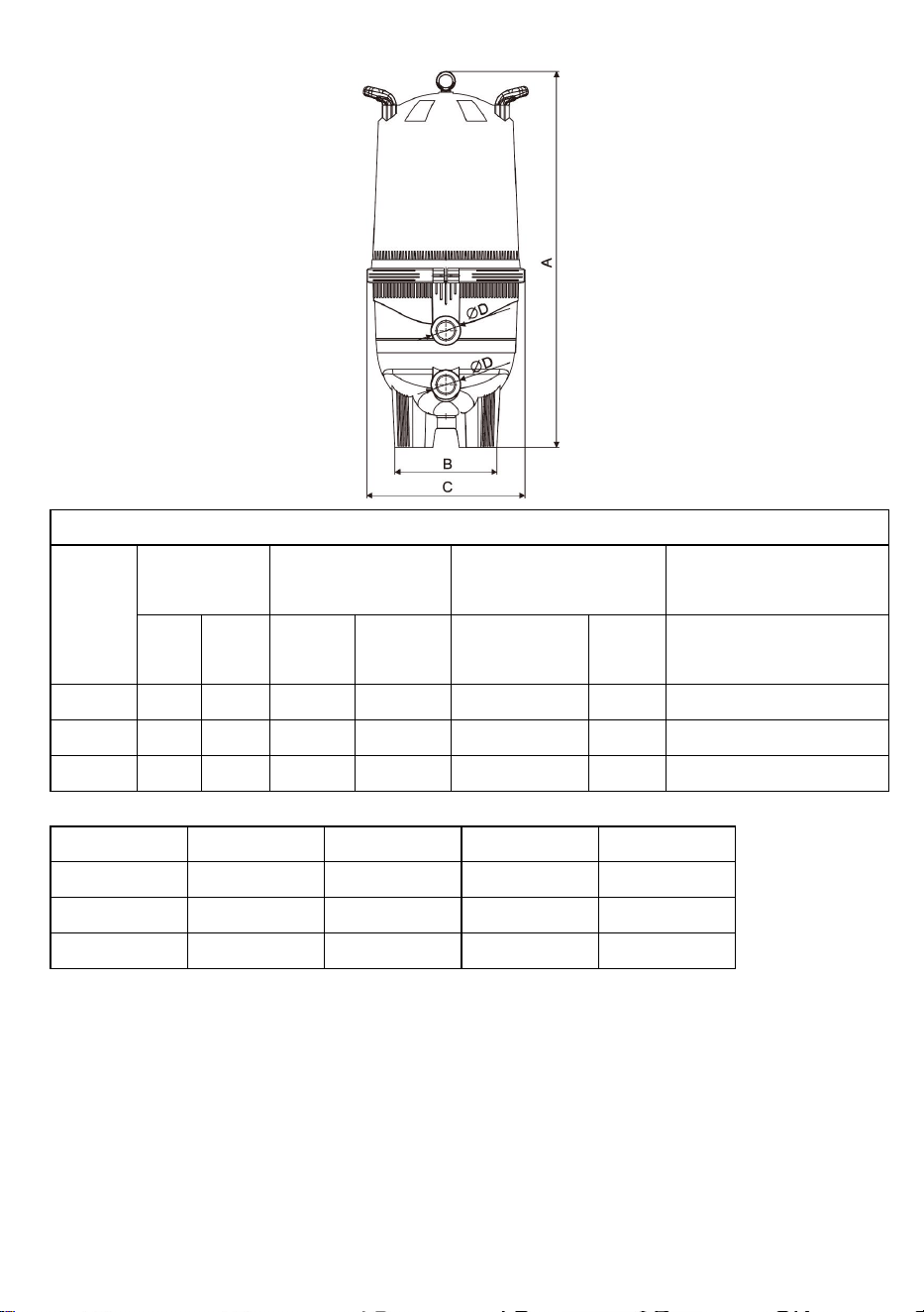
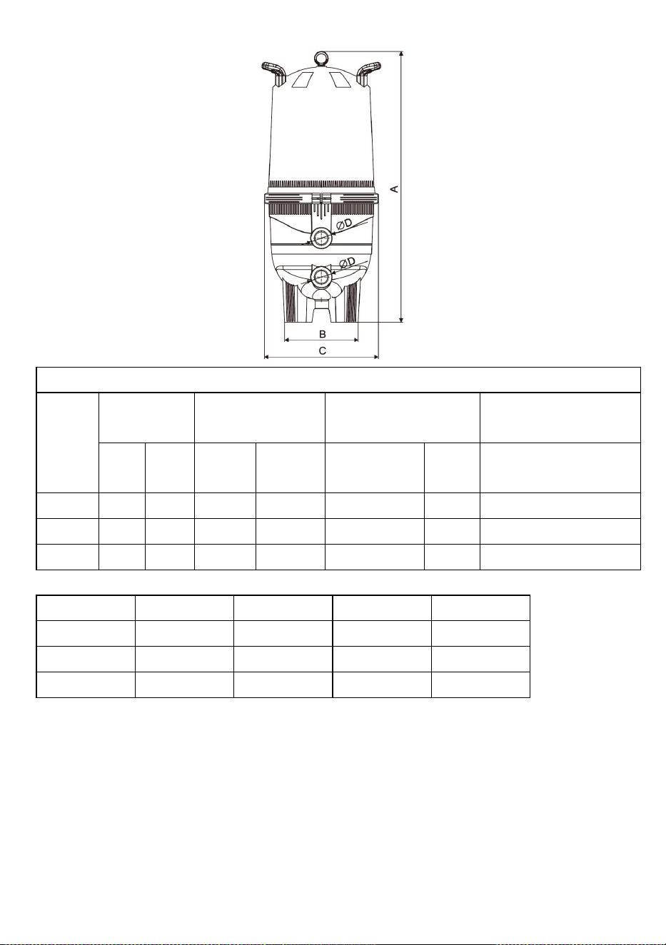
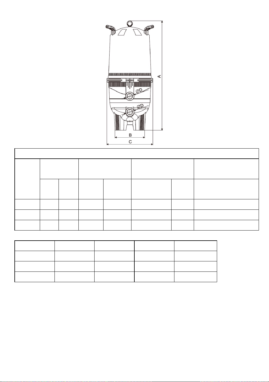
SPECIFICATIONS
Cartridge Filter Specifications
Model
Filter area
Connect size
Recommended flow
Max. working pressure
Ft
2
m
2
Inch
mm
lpm
m
3
/h
Bar
GL320
320
29.7
2
60
496.8
29.8
3
GL420
420
39
2
60
533.4
32
3
GL520
520
48.3
2
60
566.8
34
3
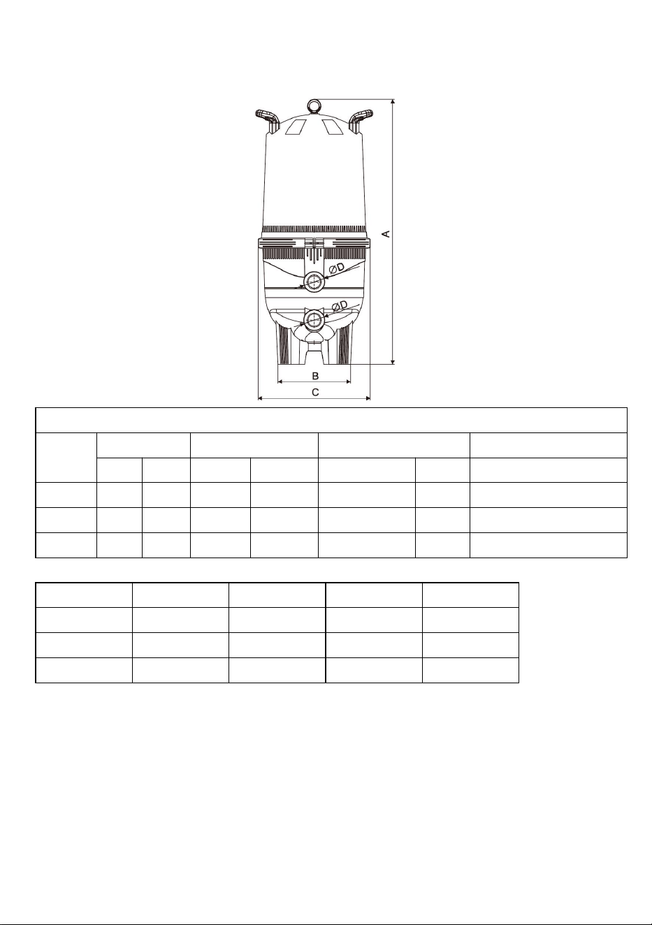
Model
A(mm)
B(mm)
C(mm)
ФD(inch)
GL320
1014
430
620
2
GL420
1169
430
620
2
GL520
1324
460
620
2
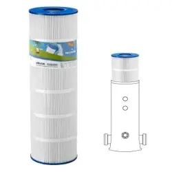
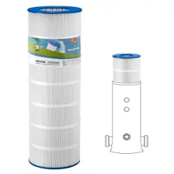
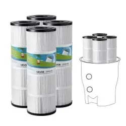
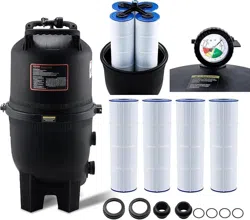
Four cartridges in a compact design
GL320-520 cartridge filters contain four polyester cartridges that hold enormous amounts of
dirt, yet are easy to clean. The fiberglass-reinforced tank halves are secured with an
innovative clamp ring-just loosen the ring and remove the top half for easy cartridge access
and rinsing. Filter maintenance made easier
Continuous internal air bleed prevents air build-up to keep the filter operating at peak
performance.
Single-piece base and body for strength, stability and years of dependable service.

7
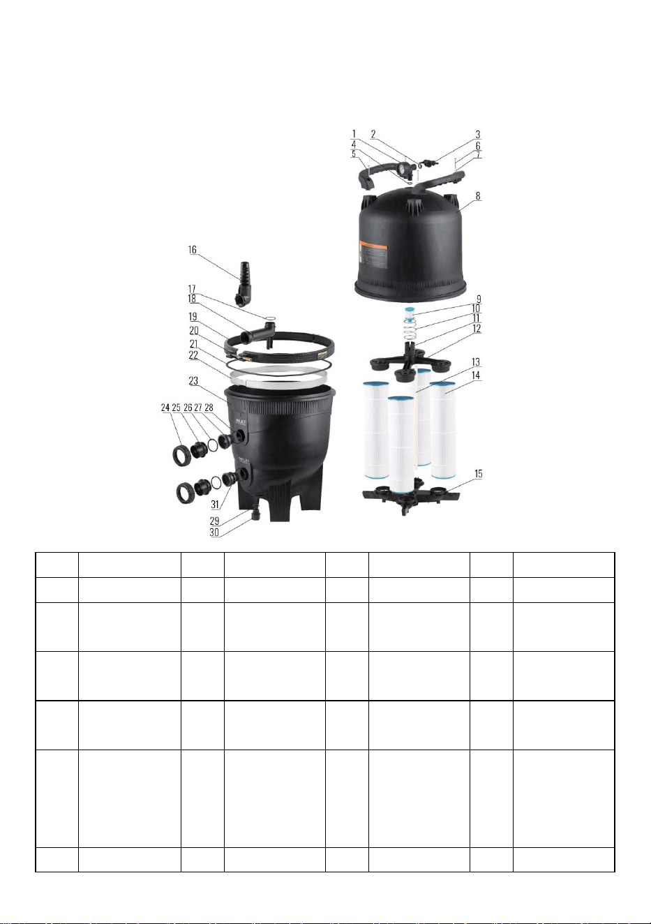
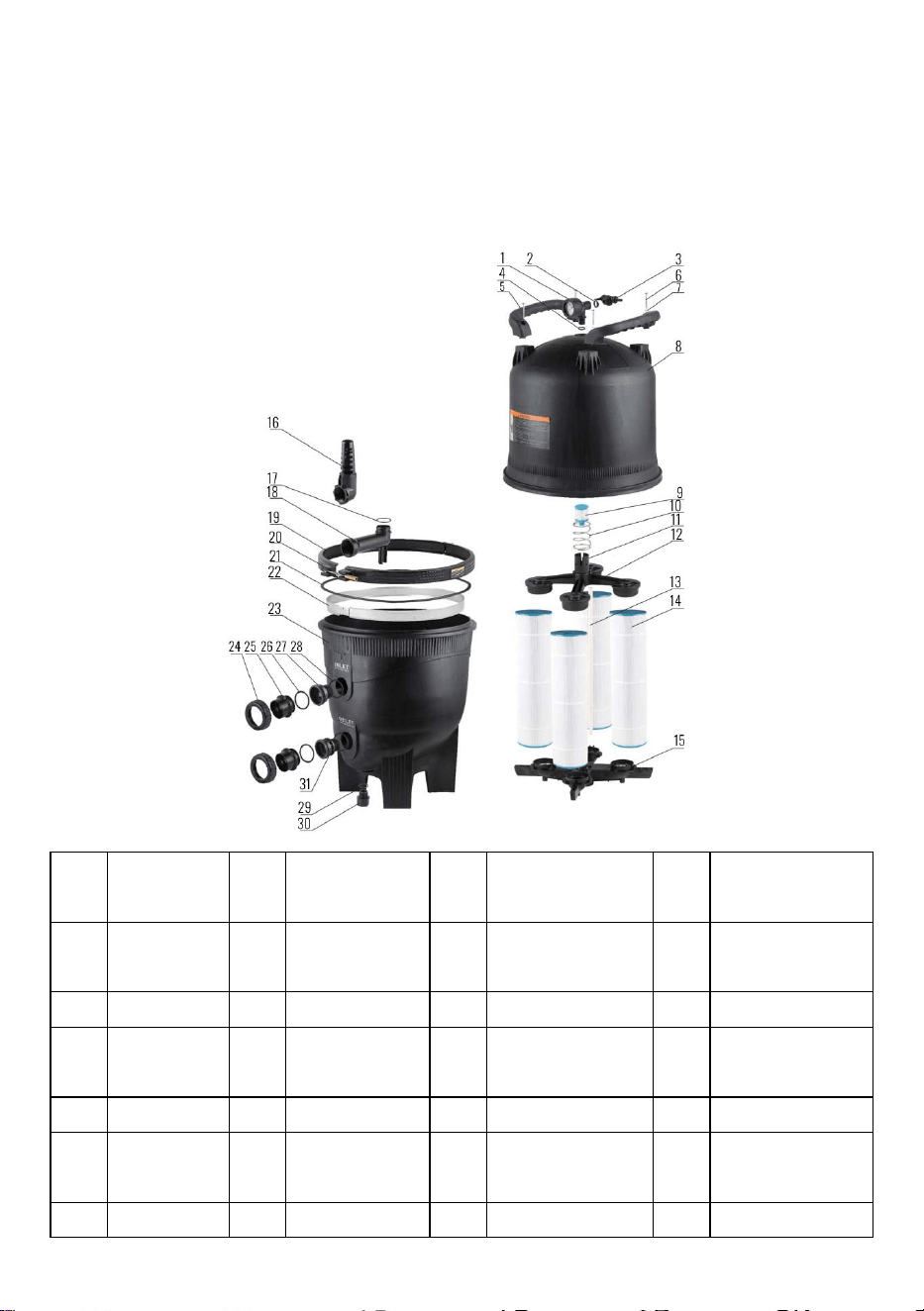
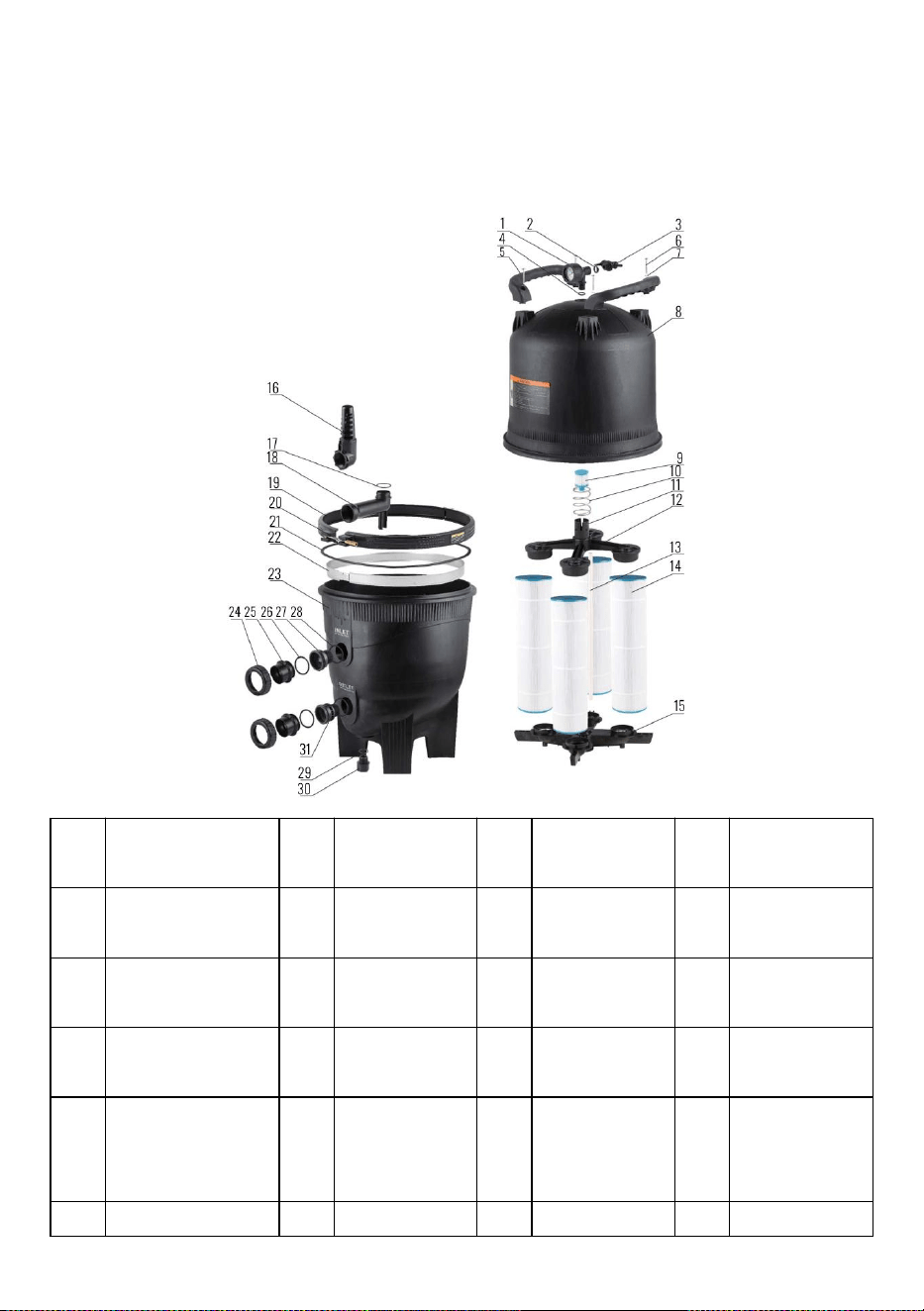
Expanded Diagram
No.
DESCRIPTION
No.
DESCRIPTION
No.
DESCRIPTION
No.
DESCRIPTION
1
Pressure Gauge
9
Cartridge
17
O Ring
25
Pipe
2
O Ring
10
Spring
18
Connect Pipe
26
O Ring
3
Valve Assembly
11
Drain Cap
19
Kit Clamp
Band
27
Union Adapter
1
4
O Ring
12
Manifold top
20
Nut-Spl
28
O Ring
5
Handle
13
Air Bleeder
Assy
21
O Ring RPM
Tank Clamp
29
O Ring
6
Screws
14
Cartridge
22
Location Band
30
Water Relief
Nut
7
Washer
15
Manifold Assy.
Bottom
23
Tank-Lower
Half
31
Union Adapter
2
8
Tank-Upper Half
Kit
16
Inlet
24
Nut
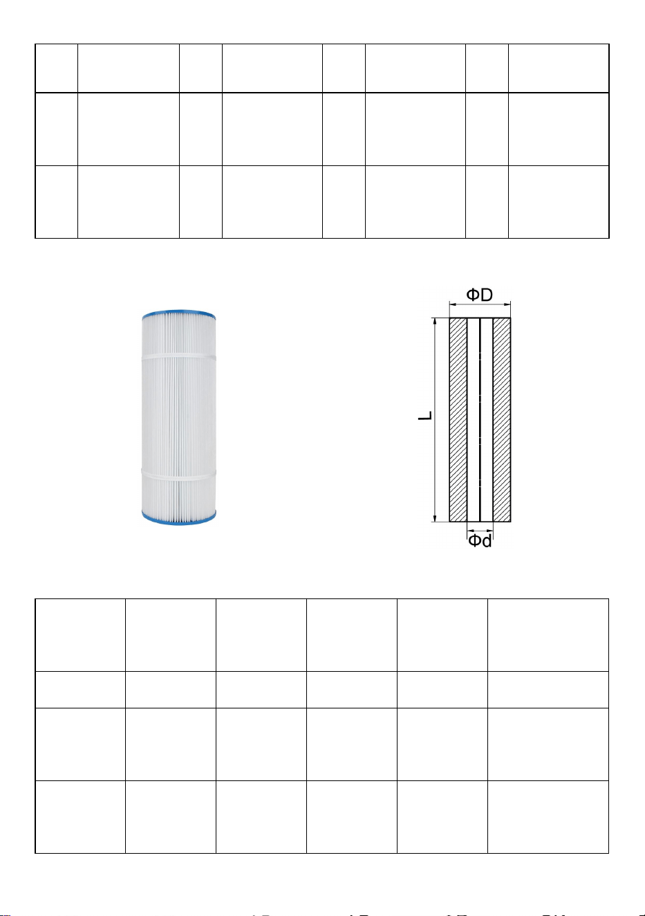
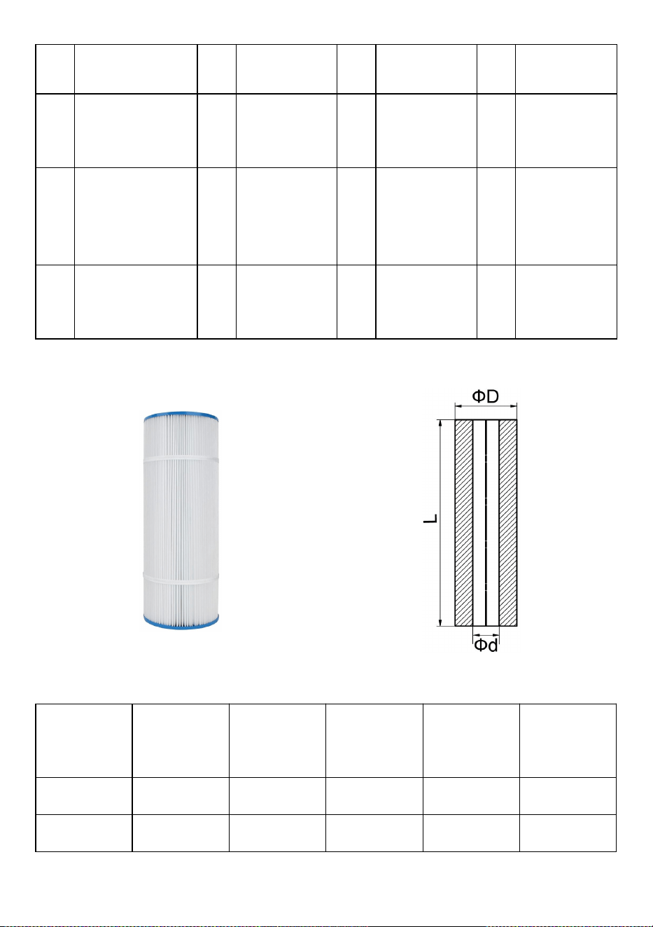
8
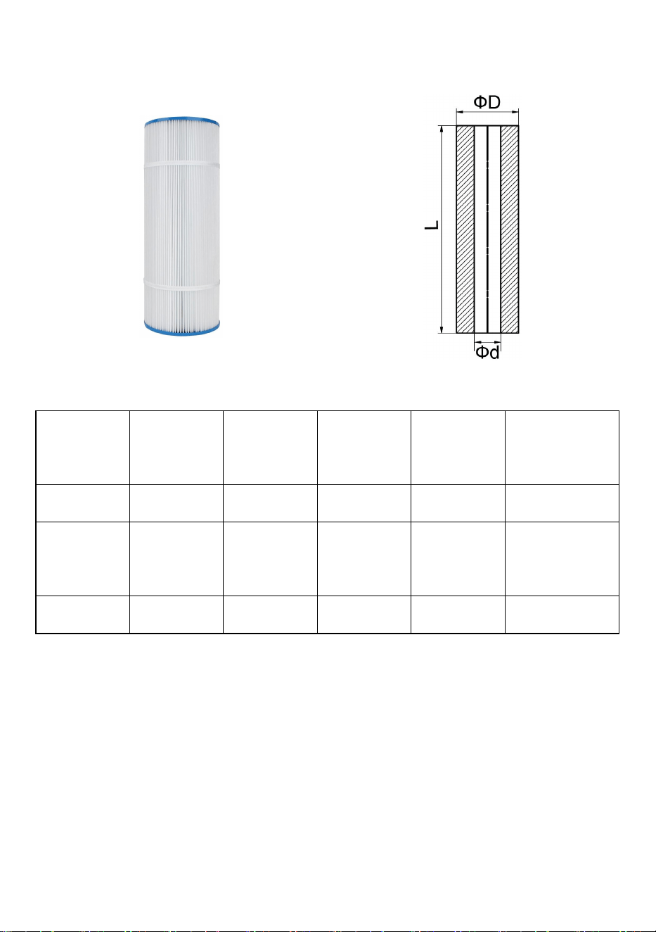
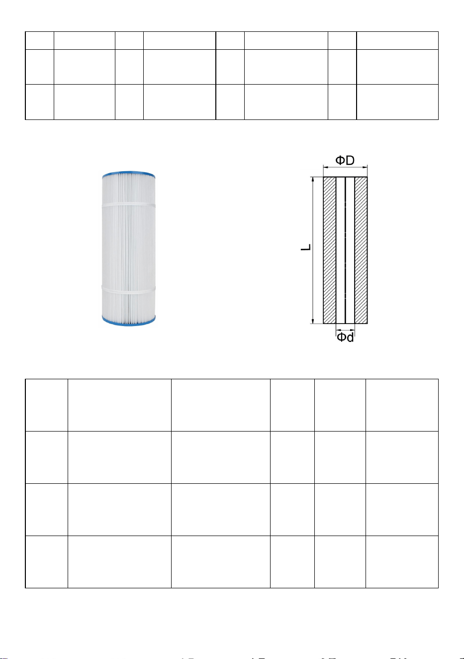
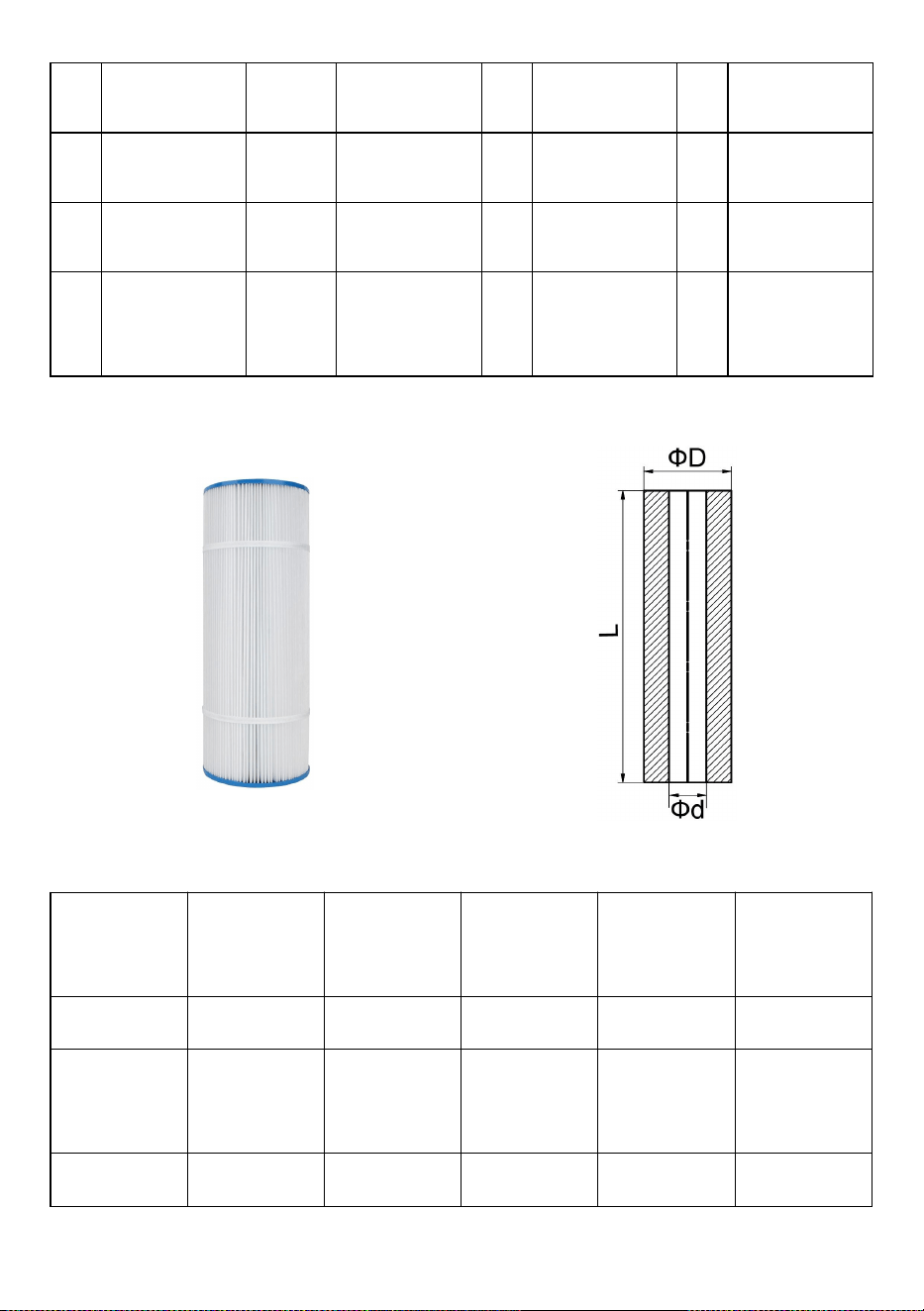
Filter Cartridge
Model
external
diameter
Internal
diameter
Length
Number
Replacement
model
GL320
178mm
76mm
508mm
4
PLFPCC80
GL420
178mm
76mm
660mm
4
C-7488
GL520
178mm
76mm
814mm
4
TRF-7472
Easy-to-clean & Reusable Cartridge Elements
Cartridges have extra dirt-holding capacity and are engineered of durable,
high-quality materials for longer service life with minimal care. Simply remove
the cartridge element and flush the cartridge with hose water or clean the
cartridge with a Filter Cleaner.
NOTICE:
After the service life of the filter Cartridges expires or is damaged, the user can
purchase other filter elements of the same size for installation .
9
WARNING
△
!
This filter operates under high pressure. When any part of the
circulating system (e.g., clamp, pump, filter, valves, etc.) is serviced, air can
enter the System and become pressurized. Pressurized air can cause the lid
or valve to Be blown off which can result in severe injury, death, or property
damage.
△
!
Turn pump off before changing the valve position.
△
!
To prevent damage to the pump and for proper operation of the system,
Clean pump strainer and skimmer baskets regularly.
Address: Baoshanqu Shuangchenglu 803long 11hao 1602A-1609shi Shanghai
Imported to AUS: SIHAO PTY LTD. 1 ROKEVA STREETEASTWOOD NSW 2122 Australia
Imported to USA: Sanven Technology Ltd. Suite 250, 9166 Anaheim Place, Rancho
Cucamonga, CA 91730
Made In China
REP
EC
SHUNSHUN GmbH
Römeräcker 9 Z2021,76351
Linkenheim-Hochstetten,Germany
REP
UK
Pooledas Group Ltd
Unit 5 Albert Edward House, The Pavilions
Preston, United Kingdom


We continue to be committed to provide you tools with competitive price.
"Save Half", "Half Price" or any other similar expressions used by us only represents an
estimate of savings you might benefit from buying certain tools with us compared to the major
top brands and does not necessarily mean to cover all categories of tools offered by us. You
are kindly reminded to verify carefully when you are placing an order with us if you are
actually saving half in comparison with the top major brands.
1
Modèle : GL320, GL420, GL520
Have product questions? Need technical support? Please feel free to
contact us:
Technical Support and E-Warranty Certificate
www.vevor.com/support
NEED HELP? CONTACT US!
This is the original instruction, please read all manual instructions
carefully before operating. VEVOR reserves a clear interpretation of our
user manual. The appearance of the product shall be subject to the
product you received. Please forgive us that we won't inform you again if
there are any technology or software updates on our product.
CARTRIDGE POOL
FILTER

2
L'installation de ce produit doit être effectuée par une personne compétente en
matière de plomberie de piscine, en suivant les instructions d'installation
fournies dans ce manuel. Veuillez transmettre ces instructions au propriétaire
de cet équipement.
FILTRE À CARTOUCHE
Félicitations pour votre achat d'un produit de qualité parmi la gamme
d'équipements de piscine et de spa disponibles auprès des systèmes de
piscine. Vous êtes assuré de nombreuses années de performances fiables et
efficaces .
Les filtres à cartouche ont été spécialement conçus pour la filtration de l'eau
des spas et des piscines. Ils ne doivent pas être utilisés à d’autres fins sans
consulter au préalable votre revendeur ou les systèmes de piscine.
Les filtres à cartouche offrent économie, hautes performances et commodité
dans un filtre sous pression bien conçu. L'élément en polyester peut être retiré
rapidement pour un nettoyage par rinçage sans perte d'eau.
Les filtres à cartouche comportent de grandes zones de filtration, qui
garantissent une distribution uniforme de l'eau, des performances de filtration
maximales et des cycles de filtration plus longs. La construction résistante à la
corrosion des filtres à cartouche offre une longue durée de vie et une
durabilité.
Les filtres à cartouche ont une capacité adaptée à la gamme de pompes de
piscine et de spa disponibles dans les systèmes de piscine, formant un
système de filtration de piscine complet conçu pour durer. Veiller à faire
correspondre les capacités de la pompe et du filtre pour obtenir un maximum
performances et efficacité.
PROCÉDÉ DE FILTRATION À CARTOUCHE
La filtration à cartouche est une méthode de filtration efficace et sans
problème. L'eau de la piscine entre dans le filtre et passe à travers une
cartouche monoélément en polyester. Les particules en suspension sont
piégées et l'eau est renvoyée vers la piscine. À mesure que l’accumulation de

3
saleté dans l’élément augmente, la pression de l’eau augmente et le débit
diminue. Lorsque la pression atteint un niveau inacceptable, l'élément doit être
retiré et nettoyé (un lavage par pulvérisation avec un tuyau d'arrosage
commun est généralement suffisant)
INSTRUCTIONS D'INSTALLATION ET D'UTILISATION
EMPLACEMENT
Le filtre doit être placé à son emplacement permanent, de préférence aussi
près que possible de la piscine ou du spa. Placez le réservoir du filtre et la
pompe sur une dalle de béton plane ou une base similaire. Prévoyez
suffisamment d’espace autour du filtre pour l’entretien de routine et prévoyez
une ventilation et un drainage adéquats. Placer la pompe en position sur la
dalle et localiser le filtre à côté du raccord d'entrée de pompe approprié orienté
vers la pompe. Reportez-vous à la section « Spécifications » pour connaître
les mesures de dégagement minimum requises pour chaque modèle.
PROTECTION CONTRE LES INTEMPÉRIES
Les filtres à cartouche sont fabriqués à partir de matériaux résistants à la
corrosion. Cependant, pour garantir des années de performances fiables, il est
recommandé que le système de filtration soit adéquatement protégé des
intempéries.
ASSEMBLÉE
Assemblez le manomètre au couvercle du filtre à l'aide de ruban téflon sur le
filetage mâle. Ne pas trop serrer.
RACCORDEMENTS DE TUYAUX

4
La tuyauterie doit être soutenue indépendamment et ne pas imposer de
lourdes charges sur le filtre ou la pompe. Utilisez un tuyau PV C de 40 mm ou
50 mm pour les conduites de retour de la pompe et de la piscine. 50 mm
doivent toujours être utilisés si la longueur du tuyau est supérieure à 15 mm.
Les filtres à cartouche sont fournis avec des raccords rapides adaptés aux
tuyaux LDPVC de 40 mm ou aux raccords de 50 mm de diamètre extérieur. Si
la pompe et le filtre sont situés en dessous du niveau de l'eau de la piscine, il
est nécessaire d'installer des vannes d'isolement dans le tuyau entre la pompe
et la piscine, et dans le conduite de retour du filtre à la piscine.
3) Pompe pour filtrer
Les filtres à cartouche sont équipés de deux ports d'entrée marqués « INLET ».
Sélectionnez le port d'entrée le plus approprié pour l'installation et branchez
l'autre port d'entrée avec le capuchon obturateur fourni. À l'aide de raccords à
connexion rapide, connectez la tuyauterie de refoulement de la pompe de
piscine aux raccords du port d'entrée sélectionnés, connectez la tuyauterie de
refoulement de la pompe de piscine au port d'entrée sélectionné. Serrez à la
main uniquement. Assurez-vous que le joint torique est lubrifiant et dans la
bonne position.
4) Filtrer au retour de la piscine
À l'aide de raccords rapides, connectez la tuyauterie de retour de la piscine au
raccord de filtre marqué « OUTLET ». Serrez le raccord uniquement à la main.
Assurez-vous que le joint torique du raccord est propre, lubrifié avec du
lubrifiant pour joint torique et dans la bonne position. La base du filtre est
dotée de quatre trous de montage pour permettre sa fixation, si nécessaire.
FONCTIONNEMENT DU FILTRE
8) Assurez-vous que la pompe est amorcée conformément aux instructions
du fabricant.
9) Assurez-vous que toutes les vannes sont ouvertes sur les conduites
d'aspiration et de refoulement. Assurez-vous que la vanne de purge d'air sur le
couvercle du filtre est ouverte et que l'anneau de verrouillage du couvercle est
en place et sécurisé.

5
10) Démarrez la pompe. Fermez la vanne de purge d'air lorsque l'eau est
expulsée.
11) Pour déterminer les conditions de fonctionnement correctes avec un filtre
propre, vérifiez que la lecture du manomètre est de 180 kpa ou moins.
12) Enregistrez la lecture du manomètre ou marquez la position de l’aiguille
sur la face du manomètre.
13) Faites fonctionner le filtre pendant une durée suffisante pour faire circuler
quotidiennement le volume total d’eau de la piscine. Le filtre doit également
être utilisé à tout moment lorsque la piscine est utilisée et pendant environ une
heure par la suite. En hiver, la durée de fonctionnement peut être réduite. Les
exigences de fonctionnement du filtre varient selon les applications de spa. En
fonction de la conception du système, du type et de la taille du spa. Consultez
votre constructeur ou fournisseur de spa.
14) Lorsque la lecture du manomètre est de 180 à 230 kpa supérieure à la
lecture du « filtre propre » comme indiqué en (4) ci-dessus, il est temps de
nettoyer l'élément de la cartouche (voir « Procédure de nettoyage de la
cartouche »).
PROCÉDURE DE NETTOYAGE DE LA CARTOUCHE
Lorsque la lecture de la jauge de filtre est de 50 à 70 kpa au-dessus de la
lecture de la jauge de filtre propre, le nettoyage de la cartouche à élément
unique est nécessaire. Pour effectuer les procédures de nettoyage
6) Éteignez la pompe.
7) Fermer les vannes d'isolement sur les conduites d'aspiration et de
refoulement, le cas échéant.
8) Ouvrez la vanne de purge d'air sur le couvercle du filtre. dévissez l'anneau
de verrouillage et retirez le couvercle du filtre.
9) Retirez l'élément de la cartouche.
10) Dans la plupart des cas, l'élément peut être facilement nettoyé avec un
tuyau d'arrosage, en pulvérisant à bonne vitesse directement sur les plis.

6
NOTE
Les algues, le calcium, l'argile, l'huile solaire et les huiles corporelles peuvent
former une couche sur l'élément qui peut ne pas être facilement éliminée avec
un jet d'eau normal. Ces matières peuvent être éliminées en trempant
l'élément dans un dégraissant et/ou détartrant. Votre revendeur local sera en
mesure de vous recommander des produits adaptés.
INSTRUCTION DE RÉASSEMBLAGE DE LA
CARTOUCHE
8) Installez la ou les cartouches et le tuyau central de manière à ce qu'ils
soient situés dans le robinet inférieur.
9) Assurez-vous que le joint torique du couvercle du filtre est propre, lubrifié
avec du lubrifiant pour joint torique et situé dans la rainure inférieure.
10) Remettez le couvercle et appuyez fermement en place. Vissez l'anneau
de verrouillage, un serrage manuel suffit - NE PAS TROP SERRER.
11) Assurez-vous que la pompe est amorcée conformément aux instructions
du fabricant.
12) Assurez-vous que toutes les vannes sont ouvertes sur les conduites d’
aspiration et de refoulement.
13) Démarrez la pompe.
14) Fermez la vanne de purge d'air lorsque tout l'air a été expulsé.
CARACTÉRISTIQUES
7
Spécifications du filtre à cartouche
Modèl
e
Zone de
filtre
Taille de
connexion
Débit recommandé _
_ _
Max. pression de
travail
Pi
2
m2
_
Pouce
mm
l/min
m
3
/h
Bar
GL320
320
29,7
2
60
496,8
29,8
3
GL420
420
39
2
60
533.4
32
3
GL520
520
48.3
2
60
566,8
34
3
Modèle
UN(mm)
B(mm)
C(mm)
ФD(pouces)
GL320
1014
430
620
2
GL420
1169
430
620
2
GL520
1324
460
620
2
Quatre cartouches dans un design compact
Les filtres à cartouche GL320-520 contiennent quatre cartouches en polyester qui
retiennent d'énormes quantités de saleté tout en étant faciles à nettoyer. Les moitiés du
réservoir renforcées en fibre de verre sont fixées avec un anneau de serrage innovant : il
suffit de desserrer l'anneau et de retirer la moitié supérieure pour un accès et un rinçage
faciles à la cartouche. L'entretien des filtres facilité
La purge d'air interne continue empêche l'accumulation d'air pour maintenir le filtre en
fonctionnement optimal
performance.
8
Base et corps monobloc pour plus de solidité, de stabilité et des années de service fiable.
Diagramme développé
Non.
DESCRIPTION
Non.
DESCRIPTION
Non.
DESCRIPTION
Non.
DESCRIPTION
1
Manomètre
9
Cartouche
17
Joint torique
25
Tuyau
2
Joint torique
dix
Printemps
18
Connecter le
tuyau
26
Joint torique
3
Ensemble de
vanne
11
Bouchon de
vidange
19
Kit Bande De
Serrage
27
Adaptateur
Union 1
4
Joint torique
12
Dessus du
collecteur
20
Écrou-Spl
28
Joint torique
5
Poignée
13
Ensemble de
purge d'air
21
Collier de
serrage pour
réservoir à joint
torique RPM
29
Joint torique
6
Des vis
14
Cartouche
22
Bande de
30
Écrou de
9
localisation
soulagement
de l'eau
7
Machine à
laver
15
Ensemble
collecteur. Bas
23
Moitié
inférieure du
réservoir
31
Adaptateur
Union 2
8
Kit moitié
supérieure du
réservoir
16
Entrée
24
Noix
Cartouche de filtre
Modèle
diamètre
extérieur
Diamètre
intérieur
Longueur
Nombre
Modèle de
remplacement
GL320 _
178mm
76mm
508mm
4
PLFPCC80
GL420 _
178mm
76mm
660
millimètres
4
C-7488
GL520 _
178mm
76mm
814
millimètres
4
TRF-7472

10
Éléments de cartouche faciles à nettoyer et réutilisables
Les cartouches ont une capacité supplémentaire de rétention de la saleté et
sont conçues à partir de matériaux durables de haute qualité pour une durée
de vie plus longue avec un minimum d'entretien. Retirez simplement l'élément
de la cartouche et rincez la cartouche avec de l'eau du tuyau ou nettoyez la
cartouche avec un nettoyant pour filtre.
AVIS:
Une fois la durée de vie des cartouches filtrantes expirée ou endommagée,
l'utilisateur peut acheter d'autres éléments filtrants de la même taille pour
l'installation.
AVERTISSEMENT
△
!
Ce filtre fonctionne sous haute pression. Lorsqu'une partie du système
de circulation (par exemple, pince, pompe, filtre, vannes, etc.) est entretenue,
de l'air peut pénétrer dans le système et devenir sous pression. L'air sous
pression peut faire exploser le couvercle ou la valve, ce qui peut entraîner des
blessures graves, la mort ou des dommages matériels.
△
!
Éteignez la pompe avant de modifier la position de la vanne.
△
!
Pour éviter d'endommager la pompe et pour assurer le bon
fonctionnement du système, nettoyez régulièrement la crépine de la pompe et
les paniers du skimmer.
Adresse : Baoshanqu Shuangchenglu 803long 11hao 1602A-1609shi Shanghai
Importé en Australie : SIHAO PTY LTD . 1 ROKEVA STREETASTWOOD NSW 2122
Australie
11
Importé aux États-Unis : Sanven Technology Ltd. Bureau 250, 9166 Anaheim Place,
Rancho Cucamonga, CA 91730
Fabriqué en Chine
REP
EC
SHUNSHUN GmbH
Römeräcker 9 Z2021,76351
Linkenheim-Hochstetten,Germany
REP
UK
Pooledas Group Ltd
Unit 5 Albert Edward House, The Pavilions
Preston, United Kingdom


Technisch Support- und E-Garantie-Zertifikat www.vevor.com/support
KARTUSCHEN-POOLFILTER BENUTZERHANDBUCH
We continue to be committed to provide you tools with competitive price.
"Save Half", "Half Price" or any other similar expressions used by us only represents an
estimate of savings you might benefit from buying certain tools with us compared to the major
top brands and does not necessarily mean to cover all categories of tools offered by us. You
are kindly reminded to verify carefully when you are placing an order with us if you are
actually saving half in comparison with the top major brands.
1
Modell: GL320, GL420, GL520
Have product questions? Need technical support? Please feel free to
contact us:
Technical Support and E-Warranty Certificate
www.vevor.com/support
NEED HELP? CONTACT US!
This is the original instruction, please read all manual instructions
carefully before operating. VEVOR reserves a clear interpretation of our
user manual. The appearance of the product shall be subject to the
product you received. Please forgive us that we won't inform you again if
there are any technology or software updates on our product.
CARTRIDGE POOL
FILTER

2
Die Installation dieses Produkts sollte von einer Person durchgeführt werden,
die sich mit den Anforderungen an Schwimmbadinstallationen auskennt, und
dabei die Installationsanweisungen in diesem Handbuch befolgen. Bitte geben
Sie diese Anleitung an den Besitzer dieses Gerätes weiter.
KARTUSCHENFILTER
Herzlichen Glückwunsch zum Kauf eines Qualitätsprodukts aus der Pool- und
Spa-Ausstattung von Pool Systems. Sie können sich auf viele Jahre
zuverlässiger und effizienter Leistung verlassen .
Kartuschenfilter wurden speziell für die Filterung von Spa- und
Schwimmbadwasser entwickelt. Sie sollten nicht für andere Zwecke
verwendet werden, ohne vorher Ihren Händler oder Ihr Poolsystem zu
konsultieren.
Patronenfilter bieten Wirtschaftlichkeit, hohe Leistung und Komfort in einem
gut konzipierten Druckfilter. Das Polyesterelement kann zur Spülreinigung
ohne Wasserverlust schnell entnommen werden.
Patronenfilter verfügen über große Filterflächen, die eine gleichmäßige
Wasserverteilung, höchste Filterleistung und längere Filterzyklen
gewährleisten. Die korrosionsbeständige Konstruktion von Patronenfiltern
sorgt für eine lange Lebensdauer und Haltbarkeit.
Die Kapazität der Patronenfilter ist auf die von Pool Systems erhältlichen Pool-
und Spa-Pumpen abgestimmt und bildet ein umfassendes Poolfiltersystem,
das auf Langlebigkeit ausgelegt ist. Achten Sie darauf, die Pumpen- und
Filterkapazitäten aufeinander abzustimmen, um eine maximale Leistung zu
erzielen Leistung und Effizienz.
VERFAHREN ZUR KARTUSCHENFILTRATION
Die Kartuschenfiltration ist eine wirksame, störungsfreie und bewährte
Filtermethode. Das Poolwasser gelangt in den Filter und durchläuft eine
Polyester-Einzelelementkartusche. Schwebstoffe werden aufgefangen und
das Wasser in den Pool zurückgeführt. Mit zunehmender
Schmutzansammlung im Element steigt der Wasserdruck und der Durchfluss

3
nimmt ab. Wenn der Druck ein unzulässiges Niveau erreicht, muss das
Element entfernt und gereinigt werden (im Allgemeinen ist eine
Sprühreinigung mit einem gewöhnlichen Gartenschlauch ausreichend).
INSTALLATIONS- UND BETRIEBSANLEITUNG
STANDORT
Der Filter sollte an seinem festen Standort platziert werden, vorzugsweise so
nah wie möglich am Pool oder Spa. Stellen Sie den Filtertank und die Pumpe
auf eine ebene Betonplatte oder einen ähnlichen Untergrund. Lassen Sie rund
um den Filter ausreichend Platz für die routinemäßige Wartung und sorgen Sie
für ausreichende Belüftung und Entwässerung. Platzieren Sie die Pumpe auf
der Platte und platzieren Sie den Filter neben dem entsprechenden
Pumpeneinlassanschluss, der zur Pumpe zeigt. Die für jedes Modell
erforderlichen Mindestabstandsmaße finden Sie im Abschnitt „Technische
Daten“.
WETTERSCHUTZ
Patronenfilter bestehen aus korrosionsbeständigen Materialien. Um jedoch
jahrelange zuverlässige Leistung zu gewährleisten, wird empfohlen, das
Filtersystem ausreichend vor Witterungseinflüssen zu schützen.
MONTAGE
Montieren Sie das Manometer mit Teflonband am Außengewinde am
Filterdeckel. Nicht überdrehen.
ROHRVERBINDUNGEN
Die Rohrleitungen sollten unabhängig voneinander gestützt werden und den
Filter oder die Pumpe nicht stark belasten. Verwenden Sie 40-mm- oder

4
50-mm-PV- C- Rohre für Pumpen- und Pool-Rücklaufleitungen. 50 mm sollten
immer verwendet werden, wenn die Leitungslänge mehr als 15 mm beträgt.
Patronenfilter werden mit Schnellkupplungen geliefert, die für
40-mm-LDPVC-Rohre oder 50-mm-Außendurchmesser-Fittings geeignet sind.
Wenn sich Pumpe und Filter unterhalb des Poolwasserspiegels befinden,
müssen in der Leitung zwischen der Pumpe und dem Pool sowie im Rohr
Absperrventile eingebaut werden Rücklaufleitung vom Filter zum Pool.
5) Pumpe zum Filter
Patronenfilter sind mit zwei Einlassanschlüssen ausgestattet, die mit „INLET
“ gekennzeichnet sind. Wählen Sie den für die Installation am besten
geeigneten Einlassanschluss und verschließen Sie den anderen
Einlassanschluss mit der mitgelieferten Blindkappe. Schließen Sie mithilfe von
Schnellkupplungen die Förderleitungen der Poolpumpe an die ausgewählten
Einlassanschlusskupplungen an und schließen Sie die Förderleitungen der
Poolpumpe an den ausgewählten Einlassanschluss an. Nur von Hand
festziehen. Stellen Sie sicher, dass der O-Ring geschmiert und in der richtigen
Position ist.
6) Filter zum Poolrücklauf
Schließen Sie die Rücklaufleitung des Pools mithilfe von Schnellkupplungen
an den mit „OUTLET“ gekennzeichneten Filteranschluss an. Ziehen Sie die
Armatur nur von Hand fest. Stellen Sie sicher, dass der O-Ring an der Armatur
sauber, mit O-Ring-Schmiermittel geschmiert und in der richtigen Position ist.
Der Filtersockel ist mit vier Befestigungslöchern versehen, um bei Bedarf eine
Befestigung zu ermöglichen.
FILTERBETRIEB
15) Stellen Sie sicher, dass die Pumpe gemäß den Anweisungen des
Herstellers vorgefüllt ist.
16) Stellen Sie sicher, dass alle Ventile an der Saug- und Druckleitung
geöffnet sind. Stellen Sie sicher, dass das Entlüftungsventil am Filterdeckel
geöffnet ist und der Deckelverriegelungsring angebracht und gesichert ist.
17) Starten Sie die Pumpe. Schließen Sie das Entlüftungsventil, wenn Wasser
austritt.

5
18) Um die korrekten Betriebsbedingungen mit einem sauberen Filter zu
ermitteln, überprüfen Sie, ob der Manometerwert 180 kPa oder weniger
beträgt.
19) Notieren Sie den Messwert des Manometers oder markieren Sie die
Nadelposition auf der Vorderseite des Manometers.
20) Betreiben Sie den Filter ausreichend lange, um täglich das gesamte
Poolwasservolumen umzuwälzen. Der Filter sollte außerdem immer in Betrieb
sein, wenn der Pool in Betrieb ist und etwa eine Stunde danach. Im Winter
kann sich die Laufzeit verkürzen. Die Anforderungen an den Filterbetrieb
variieren je nach Spa-Anwendung. Abhängig vom Systemdesign, Typ und
Größe des Whirlpools. Wenden Sie sich an Ihren Bauunternehmer oder
Spa-Lieferanten.
21) Wenn der Manometerwert 180–230 kPa höher ist als der Wert für „Filter
reinigen“ wie in (4) oben, ist es Zeit, das Kartuschenelement zu reinigen
(siehe „Kartuschenreinigungsverfahren“).
REINIGUNGSVERFAHREN DER KARTUSCHE
Wenn der Anzeigewert des Filters 50–70 kPa über dem Anzeigewert des
sauberen Filters liegt, muss die Einzelelementpatrone gereinigt werden. Um
die Reinigungsvorgänge durchzuführen
11) Schalten Sie die Pumpe aus.
12) Schließen Sie die Absperrventile an den Saug- und Druckleitungen,
sofern vorhanden.
13) Öffnen Sie das Entlüftungsventil am Filterdeckel. Schrauben Sie den
Sicherungsring ab und entfernen Sie den Filterdeckel.
14) Heben Sie das Kartuschenelement heraus.
15) In den meisten Fällen lässt sich das Element leicht mit einem
Gartenschlauch reinigen, indem man ihn mit hoher Geschwindigkeit direkt auf
die Falten sprüht.

6
NOTIZ
Algen, Kalzium, Ton, Sonnenöl und Körperöle können einen Belag auf dem
Element bilden, der sich mit normalem Abspritzen möglicherweise nicht leicht
entfernen lässt. Diese Materialien können durch Einweichen des Elements in
einem Entfetter und/oder entfernt werden Entkalker. Ihr Händler vor Ort kann
Ihnen geeignete Produkte empfehlen.
ANLEITUNG ZUM ZUSAMMENBAU DER KARTUSCHE
15) Installieren Sie die Patrone(n) und das Mittelrohr so, dass es im unteren
Zapfen sitzt.
16) Stellen Sie sicher, dass der O-Ring des Filterdeckels sauber, mit
O-Ring-Schmiermittel geschmiert und in der unteren Nut sitzt.
17) Setzen Sie den Deckel wieder auf und drücken Sie ihn fest an. Schrauben
Sie den Sicherungsring fest, handfestes Anziehen reicht aus – NICHT ZU
ANZIEHEN.
18) Stellen Sie sicher, dass die Pumpe gemäß den Anweisungen des
Herstellers vorgefüllt ist.
19) Stellen Sie sicher, dass alle Ventile an der Saug- und Druckleitung
geöffnet sind.
20) Starten Sie die Pumpe.
21) Schließen Sie das Entlüftungsventil, wenn die gesamte Luft entwichen ist.
SPEZIFIKATIONEN
7
Spezifikationen des Patronenfilters
Modell
Filterbereich
Größe verbinden
Empfohlener
Durchfluss _ _ _
Max. Arbeitsdruck
2
Fuß
m
2
Zoll
mm
lpm
m
3
/h
Bar
GL320
320
29.7
2
60
496,8
29.8
3
GL420
420
39
2
60
533,4
32
3
GL520
520
48.3
2
60
566,8
34
3
Modell
A(mm)
B(mm)
C(mm)
ФD(Zoll)
GL320
1014
430
620
2
GL420
1169
430
620
2
GL520
1324
460
620
2
Vier Patronen im kompakten Design
GL320-520-Kartuschenfilter enthalten vier Polyesterkartuschen, die enorme
Schmutzmengen aufnehmen und dennoch leicht zu reinigen sind. Die glasfaserverstärkten
Tankhälften werden mit einem innovativen Klemmring gesichert. Lösen Sie einfach den
Ring und entfernen Sie die obere Hälfte, um den Zugang zur Kartusche und das Spülen zu
erleichtern. Filterwartung einfacher gemacht
Die kontinuierliche interne Entlüftung verhindert Luftansammlungen und sorgt dafür, dass
der Filter optimal arbeitet
8
Leistung.
Basis und Gehäuse aus einem Stück für Stärke, Stabilität und jahrelangen zuverlässigen
Betrieb.
Erweitertes Diagramm
NEI
N.
BESCHREI
BUNG
NEI
N.
BESCHREIBU
NG
NEI
N.
BESCHREIBUNG
NEI
N.
BESCHREIBUN
G
1
Druckanzeig
e
9
Patrone
17
O-Ring
25
Rohr
2
O-Ring
10
Frühling
18
Rohr anschließen
26
O-Ring
3
Ventilbaugr
uppe
11
Ablasskappe
19
Kit Klemmband
27
Union-Adapter 1
4
O-Ring
12
Verteiler oben
20
Mutter-Spl
28
O-Ring
5
Handh
aben
13
Entlüftungsbau
gruppe
21
O-Ring-RPM-Tan
kklemme
29
O-Ring
6
Schrauben
14
Patrone
22
Standortband
30
Wasserentlastun
9
gsmutter
7
Waschmasc
hine
15
Verteilerbaugru
ppe. Unten
23
Tank-untere Hälfte
31
Union-Adapter 2
8
Tank-Oberte
il-Kit
16
Einlass
24
Nuss
Filterkartusche, Filterpatrone
Mode
ll
Außendurchmes
ser
Innendurchmes
ser
Läng
e
Numm
er
Ersatzmod
ell
GL
320
178mm
76mm
508m
m
4
PLFPCC80
GL
420
178mm
76mm
660
mm
4
C-7488
GL
520
178mm
76mm
814
mm
4
TRF-7472
Leicht zu reinigende und wiederverwendbare Kartuschenelemente

10
Kartuschen verfügen über eine zusätzliche Schmutzaufnahmekapazität und
sind aus langlebigen, hochwertigen Materialien gefertigt, um eine längere
Lebensdauer bei minimalem Pflegeaufwand zu gewährleisten. Entfernen Sie
einfach das Kartuschenelement und spülen Sie die Kartusche mit
Schlauchwasser aus oder reinigen Sie die Kartusche mit einem Filterreiniger.
BEACHTEN:
Nach Ablauf der Lebensdauer oder Beschädigung der Filterpatronen kann der
Anwender weitere Filterelemente gleicher Größe zum Einbau erwerben.
WARNUNG
△
!
Dieser Filter arbeitet unter hohem Druck. Wenn ein Teil des
Umlaufsystems (z. B. Klemme, Pumpe, Filter, Ventile usw.) gewartet wird,
kann Luft in das System eindringen und unter Druck stehen. Unter Druck
stehende Luft kann dazu führen, dass der Deckel oder das Ventil weggeblasen
wird, was zu schweren oder tödlichen Verletzungen oder Sachschäden führen
kann.
△
!
Schalten Sie die Pumpe aus, bevor Sie die Ventilposition ändern.
△
!
Um Schäden an der Pumpe zu vermeiden und einen ordnungsgemäßen
Betrieb des Systems zu gewährleisten, reinigen Sie das Pumpensieb und die
Skimmerkörbe regelmäßig.
Adresse: Baoshanqu Shuangchenglu 803long 11hao 1602A-1609shi Shanghai
Importiert nach AUS: SIHAO PTY LTD . 1 ROKEVA STREETEASTWOOD NSW 2122
Australien
Importiert in die USA: Sanven Technology Ltd. Suite 250, 9166 Anaheim Place, Rancho
Cucamonga, CA 91730
REP
EC
SHUNSHUN GmbH
Römeräcker 9 Z2021,76351
Linkenheim-Hochstetten,Germany

11
In China hergestellt


We continue to be committed to provide you tools with competitive price.
"Save Half", "Half Price" or any other similar expressions used by us only represents an
estimate of savings you might benefit from buying certain tools with us compared to the major
top brands and does not necessarily mean to cover all categories of tools offered by us. You
are kindly reminded to verify carefully when you are placing an order with us if you are
actually saving half in comparison with the top major brands.

1
Modello: GL320, GL420, GL520
Have product questions? Need technical support? Please feel free to
contact us:
Technical Support and E-Warranty Certificate
www.vevor.com/support
NEED HELP? CONTACT US!
This is the original instruction, please read all manual instructions
carefully before operating. VEVOR reserves a clear interpretation of our
user manual. The appearance of the product shall be subject to the
product you received. Please forgive us that we won't inform you again if
there are any technology or software updates on our product.
CARTRIDGE POOL
FILTER

2
L'installazione di questo prodotto deve essere eseguita da una persona
esperta nei requisiti idraulici della piscina, seguendo le istruzioni di
installazione fornite in questo manuale. Si prega di trasmettere queste
istruzioni al proprietario dell'apparecchiatura.
FILTRO A CARTUCCIA
Congratulazioni per aver acquistato un prodotto di qualità dalla gamma di
attrezzature per piscine e spa disponibili presso Pool Systems. Avrete la
certezza di molti anni di prestazioni affidabili ed efficienti .
I filtri a cartuccia sono stati specificatamente progettati per la filtrazione
dell'acqua di terme e piscine. Non devono essere utilizzati per nessun altro
scopo senza prima consultare il rivenditore o i sistemi della piscina.
I filtri a cartuccia offrono economia, prestazioni elevate e praticità in un filtro a
pressione ben progettato. L'elemento in poliestere può essere rimosso
rapidamente per la pulizia con risciacquo senza perdita d'acqua.
I filtri a cartuccia sono dotati di ampie aree filtranti, che garantiscono una
distribuzione uniforme dell'acqua, prestazioni di filtraggio ottimali e cicli di
filtraggio più lunghi. La struttura resistente alla corrosione dei filtri a cartuccia
garantisce lunga durata e durata.
La capacità dei filtri a cartuccia è abbinata alla gamma di pompe per piscine e
spa disponibili nei sistemi per piscine, formando un sistema di filtrazione totale
della piscina costruito per durare. Fare attenzione ad abbinare la capacità
della pompa e del filtro per ottenere il massimo prestazioni ed efficienza.
PROCESSO DI FILTRAZIONE A CARTUCCIA
La filtrazione a cartuccia è un metodo di filtrazione collaudato, efficace e senza
problemi. L'acqua della piscina entra nel filtro e passa attraverso una cartuccia
monoelemento in poliestere. Le particelle sospese vengono intrappolate e
l'acqua viene restituita alla piscina. All’aumentare dell’accumulo di sporco nell’
elemento, aumenta la pressione dell’acqua e diminuisce il flusso. Quando la
pressione raggiunge un livello inaccettabile, l'elemento deve essere rimosso e

3
pulito (in genere è sufficiente il lavaggio a spruzzo con un comune tubo da
giardino)
ISTRUZIONI DI INSTALLAZIONE E FUNZIONAMENTO
POSIZIONE
Il filtro deve essere collocato nella sua posizione permanente, preferibilmente
il più vicino possibile alla piscina o alla spa. Posizionare il serbatoio del filtro e
la pompa su una lastra di cemento piana o una base simile. Lasciare spazio
sufficiente attorno al filtro per la manutenzione ordinaria e garantire
ventilazione e drenaggio adeguati. Posizionare la pompa sulla soletta e
posizionare il filtro accanto all'apposito raccordo di ingresso della pompa
orientato verso la pompa. Fare riferimento alla sezione "Specifiche" per le
misure di spazio minimo richieste per ciascun modello.
PROTEZIONE METEO
I filtri a cartuccia sono costruiti con materiali resistenti alla corrosione. Tuttavia,
per garantire anni di prestazioni affidabili, si consiglia di proteggere
adeguatamente il sistema di filtraggio dalle intemperie.
ASSEMBLEA
Assemblare il manometro al coperchio del filtro utilizzando nastro di Teflon
sulla filettatura maschio. Non stringere eccessivamente.
COLLEGAMENTI DEI TUBI
Le tubazioni devono essere supportate in modo indipendente e non imporre
carichi pesanti sul filtro o sulla pompa. Utilizzare un tubo in PVC C da 40 mm o
50 mm per le linee di ritorno della pompa e della piscina. Se la lunghezza della
tubazione supera i 15 mm, è necessario utilizzare sempre 50 mm. I filtri a

4
cartuccia sono forniti con raccordi a connessione rapida adatti per tubi LDPVC
da 40 mm o raccordi con diametro esterno di 50 mm. Se la pompa e il filtro si
trovano sotto il livello dell'acqua della piscina, è necessario montare valvole
isolanti nel tubo tra la pompa e la piscina e nel linea di ritorno dal filtro alla
piscina.
7) Pompa per filtrare
I filtri a cartuccia sono dotati di due porte di ingresso contrassegnate con
"INLET". Selezionare la porta di ingresso più adatta per l'installazione e
tappare l'altra porta di ingresso con il tappo di chiusura fornito. Utilizzando i
raccordi a collegamento rapido, collegare la tubazione di mandata della
pompa della piscina ai raccordi della porta di ingresso selezionata, collegare la
tubazione di mandata della pompa della piscina alla porta di ingresso
selezionata. Stringere solo a mano. Assicurarsi che il lubrificante dell'o'ring sia
nella posizione corretta.
8) Filtra per restituire il pool
Utilizzando i giunti a collegamento rapido, collegare la tubazione di ritorno
della piscina al raccordo del filtro contrassegnato con "OUTLET". Stringere il
raccordo solo a mano. Assicurarsi che l'o'ring sul raccordo sia pulito, lubrificato
con lubrificante per o'ring e nella posizione corretta. La base del filtro è dotata
di quattro fori di montaggio per consentirne il fissaggio, se necessario.
FUNZIONAMENTO DEL FILTRO
22) Assicurarsi che la pompa sia adescata secondo le indicazioni del
produttore.
23) Assicurarsi che tutte le valvole siano aperte sulle linee di aspirazione e di
scarico. Assicurarsi che la valvola di sfiato dell'aria sul coperchio del filtro sia
aperta e che l'anello di bloccaggio del coperchio sia in posizione e fissato.
24) Avviare la pompa. Chiudere la valvola di sfiato dell'aria quando viene
espulsa l'acqua.
25) Per determinare le condizioni operative corrette con un filtro pulito,
verificare che la lettura del manometro sia pari o inferiore a 180 kpa.
26) Registrare la lettura del manometro o segnare la posizione dell'ago sulla
parte anteriore del manometro.

5
27) Azionare il filtro per un tempo sufficiente a far circolare quotidianamente il
volume totale dell'acqua della piscina. Inoltre, il filtro deve essere utilizzato
ogni volta che la piscina è in uso e per circa un'ora dopo l'uso. Durante
l'inverno, il tempo di funzionamento potrebbe essere ridotto. I requisiti operativi
del filtro varieranno per le applicazioni spa. A seconda del design del sistema,
del tipo e delle dimensioni della spa. Consultare il costruttore o il fornitore della
spa.
28) Quando la lettura del manometro è di 180-230 kpa superiore alla lettura
del "filtro pulito" come indicato al punto (4) sopra, è il momento di pulire
l'elemento della cartuccia (vedere "Procedura di pulizia della cartuccia").
PROCEDURA DI PULIZIA DELLA CARTUCCIA
Quando la lettura del misuratore del filtro è 50-70 kpa superiore alla lettura del
misuratore del filtro pulito, è necessaria la pulizia della cartuccia a elemento
singolo. Per eseguire le procedure di pulizia
16) Spegnere la pompa.
17) Chiudere le valvole di intercettazione sulle linee di aspirazione e di scarico,
se presenti.
18) Aprire la valvola di sfiato dell'aria sul coperchio del filtro. svitare l'anello di
bloccaggio e rimuovere il coperchio del filtro.
19) Sollevare l'elemento della cartuccia.
20) Nella maggior parte dei casi l'elemento può essere facilmente pulito con
un tubo da giardino, spruzzandolo a buona velocità direttamente sulle pieghe.
NOTA
Alghe, calcio, argilla, olio solare e oli per il corpo possono formare un
rivestimento sull'elemento che non può essere facilmente rimosso con un
normale getto d'acqua. Questi materiali possono essere rimossi immergendo

6
l'elemento in uno sgrassatore e/o decalcificante. Il tuo rivenditore locale sarà
in grado di consigliarti i prodotti adatti.
ISTRUZIONI PER IL RIMONTAGGIO DELLA
CARTUCCIA
22) Installare la cartuccia/e e il tubo centrale in modo che si trovino nel
rubinetto inferiore.
23) Assicurarsi che l'o-ring del coperchio del filtro sia pulito, lubrificato con
lubrificante per o-ring e posizionato nella scanalatura inferiore.
24) Riposizionare il coperchio e premere saldamente in posizione. Avvitare
l'anello di bloccaggio, stringere a mano è sufficiente: NON STRINGERE
ECCESSIVAMENTE.
25) Assicurarsi che la pompa sia adescata secondo le indicazioni del
produttore.
26) Assicurarsi che tutte le valvole siano aperte sulle linee di aspirazione e di
scarico.
27) Avviare la pompa.
28) Chiudere la valvola di spurgo dell'aria quando tutta l'aria è stata espulsa.
SPECIFICHE
7
Specifiche del filtro a cartuccia
Modell
o
Zona filtro
Collega la
dimensione
Flusso consigliato _ _
_
Massimo. pressione
lavorativa
Pied
i
2
m2
_
Pollice
mm
lpm
m3
/
h
Sbarra
GL320
320
29.7
2
60
496,8
29.8
3
GL420
420
39
2
60
533.4
32
3
GL520
520
48.3
2
60
566.8
34
3
Modello
A(mm)
B(mm)
C(mm)
ФD(pollici)
GL320
1014
430
620
2
GL420
1169
430
620
2
GL520
1324
460
620
2
Quattro cartucce in un design compatto
I filtri a cartuccia GL320-520 contengono quattro cartucce in poliestere che trattengono
enormi quantità di sporco, ma sono facili da pulire. Le metà del serbatoio rinforzate con
fibra di vetro sono fissate con un innovativo anello di bloccaggio: basta allentare l'anello e
rimuovere la metà superiore per un facile accesso e risciacquo della cartuccia. La
manutenzione del filtro è resa più semplice
Il continuo sfiato interno dell'aria impedisce l'accumulo di aria per mantenere il filtro
funzionante al massimo
8
prestazione.
Base e corpo in un unico pezzo per resistenza, stabilità e anni di servizio affidabile.
Diagramma espanso
NO
.
DESCRIZIONE
NO
.
DESCRIZION
E
NO
.
DESCRIZION
E
NO
.
DESCRIZION
E
1
Manometro
9
Cartuccia
17
Anello
circolare
25
Tubo
2
Anello circolare
10
Primavera
18
Collegare il
tubo
26
Anello
circolare
3
Gruppo valvola
11
Tappo di
scarico
19
Kit fascetta di
serraggio
27
Adattatore
dell'Unione 1
4
Anello circolare
12
Parte
superiore del
collettore
20
Nut-Spl
28
Anello
circolare
5
Maniglia
13
Gruppo spurgo
21
Morsetto
29
Anello
9
aria
serbatoio RPM
O-Ring
circolare
6
Viti
14
Cartuccia
22
Banda di
localizzazione
30
Dado di
scarico
dell'acqua
7
Rondella
15
Gruppo
collettore.
Metter il fondo
a
23
Metà inferiore
del serbatoio
31
Adattatore
dell'Unione 2
8
Kit metà
serbatoio-superior
e
16
Ingresso
24
Noce
Cartuccia filtrante
Modello
Diametro
esterno
Diametro
interno
Lunghezza
Numero
Modello
sostitutivo
GL320 _
178 mm
76 mm
508mm
4
PLFPCC80
GL420 _
178 mm
76 mm
660 mm
4
C-7488

10
GL520 _
178 mm
76 mm
814 mm
4
TRF-7472
Elementi a cartuccia facili da pulire e riutilizzabili
Le cartucce hanno una capacità extra di trattenere lo sporco e sono progettate
con materiali durevoli e di alta qualità per una maggiore durata con una cura
minima. È sufficiente rimuovere l'elemento della cartuccia e sciacquare la
cartuccia con l'acqua del tubo o pulire la cartuccia con un detergente per filtri.
AVVISO:
Una volta scaduta o danneggiata la durata delle cartucce filtranti , l'utente può
acquistare altri elementi filtranti della stessa dimensione per l'installazione.
AVVERTIMENTO
△
! Questo filtro funziona ad alta pressione. Durante la manutenzione di
qualsiasi parte del sistema di circolazione (ad esempio morsetto, pompa, filtro,
valvole, ecc.), l'aria può entrare nel sistema e diventare pressurizzata. L'aria
pressurizzata può causare la rottura del coperchio o della valvola, con
conseguenti lesioni gravi, morte o danni materiali.
△
! Spegnere la pompa prima di modificare la posizione della valvola.
△
! Per evitare danni alla pompa e per il corretto funzionamento del sistema,
pulire regolarmente il filtro della pompa e i cestelli dello skimmer.
Indirizzo: Baoshanqu Shuangchenglu 803long 11hao 1602A-1609shi Shanghai
Importato in AUS: SIHAO PTY LTD . 1 ROKEVA STREETEASTWOOD NSW 2122
Australia
11
Importato negli Stati Uniti: Sanven Technology Ltd. Suite 250, 9166 Anaheim Place,
Rancho Cucamonga, CA 91730
Made in China
REP
EC
SHUNSHUN GmbH
Römeräcker 9 Z2021,76351
Linkenheim-Hochstetten,Germany
REP
UK
Pooledas Group Ltd
Unit 5 Albert Edward House, The Pavilions
Preston, United Kingdom


We continue to be committed to provide you tools with competitive price.
"Save Half", "Half Price" or any other similar expressions used by us only represents an
estimate of savings you might benefit from buying certain tools with us compared to the major
top brands and does not necessarily mean to cover all categories of tools offered by us. You
are kindly reminded to verify carefully when you are placing an order with us if you are
actually saving half in comparison with the top major brands.

1
Modelo: GL320, GL420, GL520
Have product questions? Need technical support? Please feel free to
contact us:
Technical Support and E-Warranty Certificate
www.vevor.com/support
NEED HELP? CONTACT US!
This is the original instruction, please read all manual instructions
carefully before operating. VEVOR reserves a clear interpretation of our
user manual. The appearance of the product shall be subject to the
product you received. Please forgive us that we won't inform you again if
there are any technology or software updates on our product.
CARTRIDGE POOL
FILTER

2
La instalación de este producto debe ser realizada por una persona con
conocimientos en requisitos de plomería para piscinas, siguiendo las
instrucciones de instalación proporcionadas en este manual. Entregue estas
instrucciones al propietario de este equipo.
FILTRO DE CARTUCHO
Felicitaciones por su compra de un producto de calidad de la gama de equipos
para piscinas y spa disponibles en Pool Systems. Tiene asegurados muchos
años de rendimiento confiable y eficiente .
Los filtros de cartucho han sido diseñados específicamente para la filtración
de agua de spas y piscinas. No deben usarse para ningún otro propósito sin
consultar primero a su distribuidor o a los sistemas de piscina.
Los filtros de cartucho brindan economía, alto rendimiento y conveniencia en
un filtro de presión bien diseñado. El elemento de poliéster se puede quitar
rápidamente para una limpieza con enjuague sin pérdida de agua.
Los filtros de cartucho cuentan con grandes áreas de filtrado, que garantizan
una distribución uniforme del agua, un rendimiento máximo de filtración y
ciclos de filtrado más largos. La construcción resistente a la corrosión de los
filtros de cartucho proporciona una larga vida útil y durabilidad.
Los filtros de cartucho tienen una capacidad que coincide con la gama de
bombas para piscinas y spas disponibles en los sistemas de piscinas, lo que
forma un sistema de filtración total para piscinas diseñado para durar. Tenga
cuidado de igualar las capacidades de la bomba y del filtro para obtener el
máximo rendimiento y eficiencia.
PROCESO DE FILTRACIÓN CON CARTUCHO
La filtración por cartucho es un método de filtración eficaz y probado y sin
problemas. El agua de la piscina ingresa al filtro y pasa a través de un
cartucho de poliéster de un solo elemento. Las partículas en suspensión
quedan atrapadas y el agua regresa a la piscina. A medida que aumenta la
acumulación de suciedad en el elemento, la presión del agua aumenta y el
flujo disminuye. Cuando la presión alcanza un nivel inaceptable, se debe

3
retirar el elemento y limpiarlo (generalmente es suficiente lavarlo con una
manguera de jardín común)
INSTRUCCIONES DE INSTALACIÓN Y OPERACIÓN
UBICACIÓN
El filtro debe colocarse en su ubicación permanente, preferiblemente lo más
cerca posible de la piscina o spa. Coloque el tanque del filtro y la bomba sobre
una losa de concreto nivelada o una base similar. Deje suficiente espacio
alrededor del filtro para el mantenimiento de rutina y proporcione ventilación y
drenaje adecuados. Coloque la bomba en su posición sobre la losa y ubique el
filtro junto a la conexión de entrada de la bomba adecuada orientada hacia la
bomba. Consulte la sección 'Especificaciones' para conocer las medidas de
espacio mínimo requeridas para cada modelo.
PROTECCIÓN DEL CLIMA
Los filtros de cartucho están construidos con materiales resistentes a la
corrosión. Sin embargo, para garantizar años de rendimiento confiable, se
recomienda que el sistema de filtración esté adecuadamente protegido de la
intemperie.
ASAMBLEA
Monte el manómetro a la tapa del filtro usando cinta de teflón en la rosca
macho. No apriete demasiado.
CONEXIONES DE TUBERÍAS
Las tuberías deben sostenerse de forma independiente y no imponer cargas
pesadas al filtro o la bomba. Utilice tubería PV C de 40 mm o 50 mm para las
líneas de retorno de la bomba y la piscina. Siempre se deben utilizar 50 mm si

4
la longitud de la tubería es superior a 15 mm. Los filtros de cartucho se
suministran con acoplamientos de conexión rápida adecuados para tuberías
de LDPVC de 40 mm o accesorios de 50 mm de diámetro exterior. Si la
bomba y el filtro están ubicados por debajo del nivel del agua de la piscina, es
necesario instalar válvulas de aislamiento en la tubería entre la bomba y la
piscina, y en el Línea de retorno del filtro a la piscina.
9) Bomba para filtrar
Los filtros de cartucho están equipados con dos puertos de entrada marcados
como "INLET". Seleccione el puerto de entrada más adecuado para la
instalación y tape el otro puerto de entrada con la tapa ciega proporcionada.
Usando acoplamientos de conexión rápida, conecte la tubería de entrega de
la bomba de la piscina a los acoplamientos del puerto de entrada
seleccionado, conecte la tubería de entrega de la bomba de la piscina al
puerto de entrada seleccionado. Apriete sólo a mano. Asegúrese de que el
o'ring esté lubricante y en la posición correcta.
10) Retorno del filtro a la piscina
Usando acoplamientos de conexión rápida, conecte la tubería de retorno de la
piscina al conector del filtro marcado como 'SALIDA'. Apriete el conector
únicamente con la mano. Asegúrese de que la junta tórica del conector esté
limpia, lubricada con lubricante para juntas tóricas y en la posición correcta.
La base del filtro cuenta con cuatro orificios de montaje para permitir su
fijación, si es necesario.
OPERACIÓN DEL FILTRO
29) Asegúrese de que la bomba esté cebada según las instrucciones del
fabricante.
30) Asegúrese de que todas las válvulas estén abiertas en las líneas de
succión y descarga. Asegúrese de que la válvula de purga de aire en la tapa
del filtro esté abierta y que el anillo de bloqueo de la tapa esté en su lugar y
asegurado.
31) Arranque la bomba. Cierre la válvula de purga de aire cuando se expulse
el agua.

5
32) Para determinar las condiciones de funcionamiento correctas con un filtro
limpio, verifique que la lectura del manómetro sea de 180 kpa o menos.
33) Registre la lectura del manómetro o marque la posición de la aguja en la
cara del manómetro.
34) Opere el filtro durante un tiempo suficiente para hacer circular el volumen
total de agua de la piscina diariamente. El filtro también debe funcionar en
todo momento en que la piscina esté en uso y durante aproximadamente una
hora después. Durante el invierno, el tiempo de funcionamiento puede verse
reducido. Los requisitos operativos del filtro variarán para las aplicaciones de
spa. Dependiendo del diseño del sistema, tipo y tamaño del spa. Consulte a
su constructor o proveedor de spa.
35) Cuando la lectura del manómetro es 180-230 kpa más alta que la lectura
de 'limpiar filtro' como en (4) arriba, es hora de limpiar el elemento del
cartucho (consulte 'Procedimiento de limpieza del cartucho).
PROCEDIMIENTO DE LIMPIEZA DEL CARTUCHO
Cuando la lectura del medidor del filtro está entre 50 y 70 kpa por encima de la
lectura del medidor del filtro limpio, se requiere limpiar el cartucho de un solo
elemento. Para realizar los procedimientos de limpieza.
21) Apague la bomba.
22) Cierre las válvulas de aislamiento en las líneas de succión y descarga,
donde estén instaladas.
23) Abra la válvula de purga de aire en la tapa del filtro. desenrosque el anillo
de bloqueo y retire la tapa del filtro.
24) Levante el elemento del cartucho.
25) En la mayoría de los casos, el elemento se puede limpiar fácilmente con
una manguera de jardín, rociando a buena velocidad directamente sobre los
pliegues.
NOTA

6
Las algas, el calcio, la arcilla, el aceite bronceador y los aceites corporales
pueden formar una capa en el elemento que no se puede eliminar fácilmente
con una manguera normal. Estos materiales se pueden eliminar sumergiendo
el elemento en un desengrasante y/o descalcificador. Su distribuidor local
podrá recomendarle productos adecuados.
INSTRUCCIONES DE REARMADO DEL CARTUCHO
29) Instale el/los cartucho/s y el tubo central de modo que quede ubicado en
el grifo inferior.
30) Asegúrese de que la junta tórica de la tapa del filtro esté limpia, lubricada
con lubricante para juntas tóricas y ubicada en la ranura inferior.
31) Vuelva a colocar la tapa y presione firmemente en su lugar. Atornille el
anillo de bloqueo; apretarlo con la mano es suficiente; NO LO APRIETE
DEMASIADO.
32) Asegúrese de que la bomba esté cebada según las instrucciones del
fabricante.
33) Asegúrese de que todas las válvulas estén abiertas en las líneas de
succión y descarga.
34) Arranque la bomba.
35) Cierre la válvula de purga de aire cuando se haya expulsado todo el aire.
ESPECIFICACIONES
7
Especificaciones del filtro de cartucho
Model
o
Área de
filtrado
Tamaño de
conexión
Flujo recomendado _
_ _
Máx. presión laboral
Pie
2
metr
os
2
Pulga
da
milímetr
os
lpm
m3
/
h
Bar
GL320
320
29,7
2
60
496,8
29,8
3
GL420
420
39
2
60
533.4
32
3
GL520
520
48.3
2
60
566,8
34
3
Modelo
Un(mm)
B(mm)
C(mm)
ФD(pulgadas)
GL320
1014
430
620
2
GL420
1169
430
620
2
GL520
1324
460
620
2
Cuatro cartuchos en un diseño compacto
Los filtros de cartucho GL320-520 contienen cuatro cartuchos de poliéster que retienen
enormes cantidades de suciedad y son fáciles de limpiar. Las mitades del tanque
reforzadas con fibra de vidrio están aseguradas con un innovador anillo de sujeción;
simplemente afloje el anillo y retire la mitad superior para acceder fácilmente al cartucho y
enjuagarlo. El mantenimiento del filtro es más fácil
La purga de aire interna continua evita la acumulación de aire para mantener el filtro
funcionando al máximo.

8
actuación.
Base y cuerpo de una sola pieza para mayor resistencia, estabilidad y años de servicio
confiable.
Diagrama ampliado
No
.
DESCRIPCIÓ
N
No.
DESCRIPCIÓ
N
No
.
DESCRIPCIÓ
N
No
.
DESCRIPCIÓ
N
1
Manómetro
9
Cartucho
17
Anillo O
25
Tubo
2
Anillo O
10
Primavera
18
Conectar
tubería
26
Anillo O
3
Conjunto de
válvula
11
Tapa de
drenaje
19
Kit de banda
de sujeción
27
Adaptador de
unión 1
4
Anillo O
12
Parte superior
del colector
20
Tuerca-Spl
28
Anillo O
5
Manejar
13
Conjunto de
purga de aire
21
Abrazadera del
tanque de
29
Anillo O
9
RPM con junta
tórica
6
Tornillos
14
Cartucho
22
Banda de
ubicación
30
Tuerca de
alivio de agua
7
Lavadora
15
Conjunto de
colector. Abajo
23
Mitad inferior
del tanque
31
Adaptador de
unión 2
8
Kit de mitad
superior del
tanque
dieciséi
s
Entrada
24
Tuerca
Cartucho de filtro
Modelo
diámetro
externo
Diámetro
interno
Longitud
Número
Modelo de
reemplazo
GL 320
178mm
76mm
508mm
4
PLFPCC80
GL 420
178mm
76mm
660
milímetros
4
C-7488
GL 520
178mm
76mm
814
4
TRF-7472

10
milímetros
Elementos de cartucho reutilizables y fáciles de limpiar
Los cartuchos tienen una capacidad adicional de retención de suciedad y
están diseñados con materiales duraderos y de alta calidad para una vida útil
más larga con un cuidado mínimo. Simplemente retire el elemento del
cartucho y enjuague el cartucho con agua de manguera o limpie el cartucho
con un limpiador de filtros.
AVISO:
Una vez que la vida útil de los cartuchos de filtro expire o se dañe, el usuario
puede comprar otros elementos filtrantes del mismo tamaño para su
instalación.
ADVERTENCIA
△
!
Este filtro funciona a alta presión. Cuando se realiza mantenimiento a
cualquier parte del sistema de circulación (p. ej., abrazadera, bomba, filtro,
válvulas, etc.), el aire puede ingresar al sistema y presurizarse. El aire
presurizado puede hacer que la tapa o la válvula se salgan, lo que puede
provocar lesiones graves, la muerte o daños a la propiedad.
△
!
Apague la bomba antes de cambiar la posición de la válvula.
△
!
Para evitar daños a la bomba y para el funcionamiento adecuado del
sistema, limpie el colador de la bomba y las cestas del skimmer con
regularidad.
Dirección: Baoshanqu Shuangchenglu 803long 11hao 1602A-1609shi Shanghai
Importado a AUS: SIHAO PTY LTD . 1 ROKEVA STREET ASTWOOD NSW 2122 Australia

11
Importado a EE. UU.: Sanven Technology Ltd. Suite 250, 9166 Anaheim Place, Rancho
Cucamonga, CA 91730
Hecho en china
REP
EC
SHUNSHUN GmbH
Römeräcker 9 Z2021,76351
Linkenheim-Hochstetten,Germany
REP
UK
Pooledas Group Ltd
Unit 5 Albert Edward House, The Pavilions
Preston, United Kingdom


Teknisk Support och e-garanticertifikat www.vevor.com/support
PATRON POOLFILTER ANVÄNDARMANUAL
We continue to be committed to provide you tools with competitive price.
"Save Half", "Half Price" or any other similar expressions used by us only represents an
estimate of savings you might benefit from buying certain tools with us compared to the major
top brands and does not necessarily mean to cover all categories of tools offered by us. You
are kindly reminded to verify carefully when you are placing an order with us if you are
actually saving half in comparison with the top major brands.

1
Modell: GL320, GL420, GL520
Have product questions? Need technical support? Please feel free to
contact us:
Technical Support and E-Warranty Certificate
www.vevor.com/support
NEED HELP? CONTACT US!
This is the original instruction, please read all manual instructions
carefully before operating. VEVOR reserves a clear interpretation of our
user manual. The appearance of the product shall be subject to the
product you received. Please forgive us that we won't inform you again if
there are any technology or software updates on our product.
CARTRIDGE POOL
FILTER

2
Installationen av den här produkten bör utföras av en person som är kunnig
inom VVS-krav för pooler, enligt installationsinstruktionerna i denna manual.
Vänligen lämna dessa instruktioner vidare till ägaren av denna utrustning.
PATRONFILTER
Grattis till ditt köp av en kvalitetsprodukt från sortimentet av pool- och
spautrustning som finns tillgänglig från poolsystem. Du är säker på många år
av pålitlig och effektiv prestanda .
Patronfilter har utformats speciellt för filtrering av spa- och poolvatten. De bör
inte användas för något annat ändamål utan att först rådfråga din
återförsäljare eller poolsystem.
Patronfilter ger ekonomi, hög prestanda och bekvämlighet i ett väldesignat
tryckfilter. Polyesterelementet kan tas bort snabbt för sköljning utan
vattenförlust.
Patronfilter har stora filterytor som säkerställer jämn vattenfördelning,
toppfiltreringsprestanda och längre filtercykler. Den korrosionsbeständiga
konstruktionen av patronfilter ger lång livslängd och hållbarhet.
Patronfilter är kapacitetsmatchade med utbudet av pool- och spapumpar som
finns tillgängliga från poolsystem, vilket bildar ett totalt poolfiltreringssystem
byggt för att hålla. Se till att matcha pump- och filterkapaciteten för att få
maximal prestanda och effektivitet.
PATRONFILTRERINGSPROCESS
Patronfiltrering är en effektiv problemfri beprövad filtreringsmetod. Poolvatten
kommer in i filtret och passerar genom en polyesterpatron med ett element.
Suspenderade partiklar fångas och vattnet återförs till poolen. När
uppbyggnaden av smuts i elementet ökar, så ökar vattentrycket och flödet
minskar. När trycket når en oacceptabel nivå måste elementet tas bort och
rengöras (spraytvätt med en vanlig trädgårdsslang är i allmänhet tillräckligt)
INSTALLATIONS- OCH DRIFTINSTRUKTIONER

3
PLATS
Filtret bör placeras på sin permanenta plats, helst så nära poolen eller spaet
som möjligt. Placera filtertanken och pumpen på en plan betongplatta eller
liknande underlag. Lämna tillräckligt med utrymme runt filtret för rutinunderhåll
och se till att det finns tillräcklig ventilation och dränering. Placera pumpen på
plats på plattan och placera filtret bredvid lämplig pumpinloppsanslutning
riktad mot pumpen. Se avsnittet "Specifikationer" för de minsta spelmått som
krävs för varje modell.
VÄDERSKYDD
Patronfilter är tillverkade av korrosionsbeständiga material. Men för att
säkerställa åratal av tillförlitlig prestanda, rekommenderas det att
filtreringssystemet är tillräckligt skyddat mot väder och vind.
HOPSÄTTNING
Montera tryckmätaren på filterlocket med teflontejp på hangängan. Dra inte åt
för hårt.
RÖRANSLUTNINGAR
Rörledningar bör stödjas oberoende och inte belasta filtret eller pumpen tungt.
Använd 40 mm eller 50 mm PV C- rör för pump- och poolreturledningar. 50
mm ska alltid användas om längden på rören är över 15 mm. Patronfilter
levereras med snabbkopplingar lämpliga för 40 mm LDPVC-rör eller 50 mm
OD-kopplingar. Om pumpen och filtret är placerade under poolvattennivån är
det nödvändigt att montera avstängningsventiler i röret mellan pumpen och
poolen, och i returledning från filtret till poolen.
11) Pumpa för att filtrera
Patronfilter är utrustade med två inloppsportar märkta 'INLET'. Välj den
inloppsport som är bäst lämpad för installationen och anslut den andra
inloppsporten med det medföljande skyddslocket. Använd snabbkopplingar,

4
anslut poolpumpens tillförselrör till de valda inloppsportens kopplingar, anslut
poolpumpens tillförselrör till den valda inloppsporten. Dra åt endast för hand.
Se till att o-ringens smörjmedel är i rätt läge.
12) Filter till poolretur
Använd snabbkopplingar och anslut poolens returrör till filterkopplingen märkt
'OUTLET'. Dra åt kopplingen endast för hand. Se till att o-ringen på beslaget är
ren, smord med o-ringssmörjmedel och i rätt läge. Filterbasen är försedd med
fyra monteringshål så att den kan säkras vid behov.
FILTERFUNKTION
36) Se till att pumpen är fylld enligt tillverkarens anvisningar.
37) Se till att alla ventiler är öppna på sug- och utloppsledningarna. Se till att
luftavluftningsventilen på filterlocket är öppen och att lockets låsring är på plats
och säkert.
38) Starta pumpen. Stäng avluftningsventilen när vatten strömmar ut.
39) För att fastställa de korrekta driftsförhållandena med ett rent filter,
kontrollera att tryckmätarens avläsning är 180kpa eller lägre.
40) Registrera tryckmätarens avläsning eller markera nålens position på
tryckmätarens framsida.
41) Använd filtret tillräckligt länge för att cirkulera den totala
poolvattenvolymen dagligen. Filtret bör också användas när poolen används
och i ungefär en timme efteråt. Under vintern kan körtiden minskas.
Filterdriftskraven kommer att variera för spaapplikationer. Beroende på
systemets design, typ och storlek på spabadet. Rådfråga din byggare eller
spa-leverantör.
42) När tryckmätarens avläsning är 180-230 kpa högre än "rent
filter"-avläsning som i (4) ovan, är det dags att rengöra patronelementet (se
'Patronrengöringsprocedur).
PROCEDUR FÖR RENGÖRING AV PATRONEN

5
När filtermätarens avläsning är 50-70kpa över den rena filtermätaren, krävs
rengöring av enelementspatronen. För att utföra rengöringsprocedurerna
26) Stäng av pumpen.
27) Stäng avstängningsventiler på sug- och utloppsledningar där sådana
finns.
28) Öppna luftavluftningsventilen på filterlocket. skruva loss låsringen och ta
bort filterlocket.
29) Lyft ut patronelementet.
30) I de flesta fall kan elementet enkelt rengöras med en trädgårdsslang, med
bra hastighet sprayas direkt på vecken.
NOTERA
Alger, kalcium, lera, sololja och kroppsoljor kan bilda en beläggning på
elementet som kanske inte lätt kan avlägsnas med normal spolning. Dessa
material kan avlägsnas genom att blötlägga elementet i en avfettningsmedel
och/eller avkalkningsmedel. Din lokala återförsäljare kommer att kunna
rekommendera lämpliga produkter.
INSTRUKTION FÖR ÅTERMONTERING AV PATRONEN
36) Installera patronen/patronerna och mittröret så att det är placerat i
bottentappen.
37) Se till att filterlockets o-ring är ren, smord med o-ring-smörjmedel och
placerad i det nedre spåret.
38) Sätt tillbaka locket och tryck ordentligt på plats. Skruva ner låsringen, det
räcker med att dra åt för hand - DRA INTE FÖR ÖVER.
39) Se till att pumpen är fylld enligt tillverkarens anvisningar.
40) Se till att alla ventiler är öppna på sug- och utloppsledningarna.
41) Starta pumpen.
42) Stäng avluftningsventilen när all luft har dragits ut.
SPECIFIKATIONER
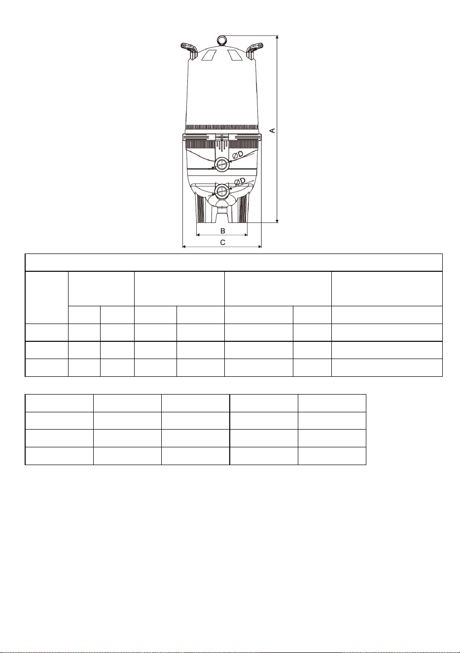
6
Patronfilterspecifikationer
Modell
Filterområd
e
Anslut storlek
Rekommenderat
flöde _ _ _
Max. arbetstryck
Ft
2
m
2
Tum
mm
lpm
m3
/
h
Bar
GL320
320
29,7
2
60
496,8
29,8
3
GL420
420
39
2
60
533,4
32
3
GL520
520
48,3
2
60
566,8
34
3
Modell
A(mm)
B(mm)
C(mm)
ФD(tum)
GL320
1014
430
620
2
GL420
1169
430
620
2
GL520
1324
460
620
2
Fyra patroner i kompakt design
GL320-520 patronfilter innehåller fyra polyesterpatroner som rymmer enorma mängder
smuts, men som ändå är lätta att rengöra. De glasfiberförstärkta tankhalvorna är säkrade
med en innovativ klämring - bara lossa ringen och ta bort den övre halvan för enkel åtkomst
av patronen och sköljning. Filterunderhåll underlättas
Kontinuerlig intern luftavtappning förhindrar luftansamling för att hålla filtret i drift på topp
prestanda.
Bas och kropp i ett stycke för styrka, stabilitet och år av pålitlig service.
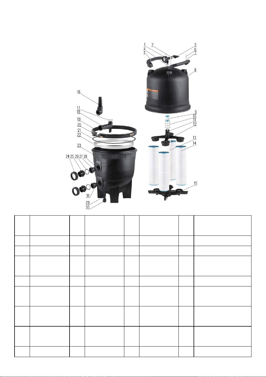
7
Utökat diagram
Nej
.
BESKRIVNIN
G
Nej
.
BESKRIVNIN
G
Nej
.
BESKRIVNIN
G
Nej
.
BESKRIVNING
1
Tryckmätare
9
Patron
17
O Ring
25
Rör
2
O Ring
10
Vår
18
Anslut rör
26
O Ring
3
Ventilmonterin
g
11
Avloppslock
19
Kit klämband
27
Union Adapter 1
4
O Ring
12
Fördelartopp
20
Nut-Spl
28
O Ring
5
Hantera
13
Air Bleeder
Assy
21
O Ring RPM
Tank Clamp
29
O Ring
6
Skruvar
14
Patron
22
Plats Band
30
Vattenavlastningsmutt
er
7
Bricka
15
Manifold Assy.
Botten
23
Tank-undre
halvan
31
Union Adapter 2
8
Tank-Upper
16
Inlopp
24
Nöt
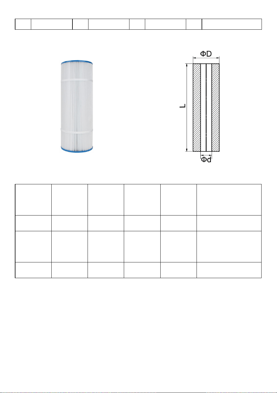
8
Half Kit
Filterpatron
Modell
yttre
diameter
Inre
diameter
Längd
siffra
Ersättningsmodell
GL 320
178 mm
76 mm
508 mm
4
PLFPCC80
GL 420
178 mm
76 mm
660 mm
4
C-7488
GL 520
178 mm
76 mm
814 mm
4
TRF-7472
Lätt att rengöra och återanvändbara patronelement
C- artridges har extra smutshållande kapacitet och är konstruerade av hållbara,
högkvalitativa material för längre livslängd med minimal skötsel. Ta helt enkelt
bort patronelementet och spola patronen med vattenslang eller rengör
patronen med en filterrengörare.
LÄGGA MÄRKE TILL:
Efter att livslängden för filterpatronerna har gått ut eller är skadade kan
användaren köpa andra filterelement av samma storlek för installation.
9
VARNING
△
!
Detta filter arbetar under högt tryck. När någon del av det cirkulerande
systemet (t.ex. klämma, pump, filter, ventiler etc.) servas kan luft komma in i
systemet och bli trycksatt. Tryckluft kan orsaka att locket eller ventilen blåses
av vilket kan resultera i allvarliga skador, dödsfall eller skador på egendom.
△
!
Stäng av pumpen innan du ändrar ventilens läge.
△
!
För att förhindra skador på pumpen och för att systemet ska fungera
korrekt, rengör pumpsilen och skimmerkorgar regelbundet.
Adress: Baoshanqu Shuangchenglu 803long 11hao 1602A-1609shi Shanghai
Importerad till AUS: SIHAO PTY LTD . 1 ROKEVA STREETEASTWOOD NSW 2122
Australien
Importerad till USA: Sanven Technology Ltd. Suite 250, 9166 Anaheim Place, Rancho
Cucamonga, CA 91730
Tillverkad i Kina
REP
EC
SHUNSHUN GmbH
Römeräcker 9 Z2021,76351
Linkenheim-Hochstetten,Germany
REP
UK
Pooledas Group Ltd
Unit 5 Albert Edward House, The Pavilions
Preston, United Kingdom


We continue to be committed to provide you tools with competitive price.
"Save Half", "Half Price" or any other similar expressions used by us only represents an
estimate of savings you might benefit from buying certain tools with us compared to the major
top brands and does not necessarily mean to cover all categories of tools offered by us. You
are kindly reminded to verify carefully when you are placing an order with us if you are
actually saving half in comparison with the top major brands.
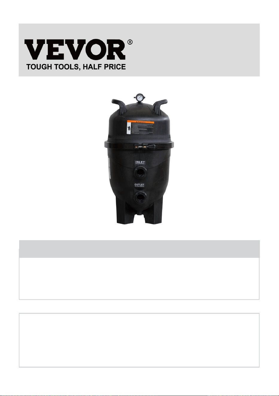
1
Modele: GL320, GL420, GL520
Have product questions? Need technical support? Please feel free to
contact us:
Technical Support and E-Warranty Certificate
www.vevor.com/support
NEED HELP? CONTACT US!
This is the original instruction, please read all manual instructions
carefully before operating. VEVOR reserves a clear interpretation of our
user manual. The appearance of the product shall be subject to the
product you received. Please forgive us that we won't inform you again if
there are any technology or software updates on our product.
CARTRIDGE POOL
FILTER

2
Instalacja tego produktu powinna zostać przeprowadzona przez osobę
znającą wymagania dotyczące instalacji wodno-kanalizacyjnej basenu,
zgodnie z instrukcjami instalacji zawartymi w niniejszej instrukcji. Prosimy o
przekazanie niniejszej instrukcji właścicielowi tego urządzenia.
FILTR WKŁADOWY
Gratulujemy zakupu wysokiej jakości produktu z asortymentu sprzętu
basenowego i spa dostępnego w firmie Pool Systems . Masz pewność
wieloletniej, niezawodnej i wydajnej pracy .
Filtry kasetowe zostały specjalnie zaprojektowane do filtracji wody w basenach
i spa. Nie należy ich używać do żadnych innych celów bez uprzedniej
konsultacji ze sprzedawcą lub systemami basenowymi.
Filtry kasetowe zapewniają oszczędność, wysoką wydajność i wygodę w
dobrze zaprojektowanym filtrze ciśnieniowym. Element poliestrowy można
szybko i bez utraty wody wyjąć w celu oczyszczenia poprzez płukanie.
Filtry kasetowe charakteryzują się dużą powierzchnią filtracyjną, która
zapewnia równomierną dystrybucję wody, najwyższą wydajność filtracji i
dłuższe cykle filtrowania. Odporna na korozję konstrukcja filtrów kasetowych
zapewnia długą żywotność i trwałość.
Filtry kasetowe mają pojemność dostosowaną do gamy pomp basenowych i
spa dostępnych w systemach basenowych, tworząc kompletny system filtracji
basenu zbudowany z myślą o trwałości. Aby uzyskać maksimum, należy
zadbać o dopasowanie wydajności pompy i filtra wydajność i efektywność.
PROCES FILTRACJI WKŁADOWEJ
Filtracja kasetowa to skuteczna i bezawaryjna sprawdzona metoda filtracji.
Woda basenowa wpływa do filtra i przechodzi przez jednoelementowy wkład
poliestrowy. Zawieszone cząstki są wychwytywane, a woda wraca do basenu.
W miarę wzrostu ilości zanieczyszczeń w elemencie wzrasta ciśnienie wody i
zmniejsza się przepływ. Gdy ciśnienie osiągnie nieakceptowalny poziom
należy element zdemontować i oczyścić (przeważnie wystarczy umycie
natryskowe zwykłym wężem ogrodowym)

3
INSTRUKCJA MONTAŻU I OBSŁUGI
LOKALIZACJA
Filtr należy umieścić w stałym miejscu, najlepiej jak najbliżej basenu lub spa.
Umieścić zbiornik filtra i pompę na płaskiej płycie betonowej lub podobnym
podłożu. Należy pozostawić wokół filtra wystarczającą ilość miejsca na
potrzeby rutynowej konserwacji oraz zapewnić odpowiednią wentylację i
drenaż. Umieścić pompę na płycie i umieścić filtr obok odpowiedniego
przyłącza wlotowego pompy, skierowanego w stronę pompy. Informacje na
temat minimalnych wymiarów prześwitu wymaganych dla każdego modelu
można znaleźć w części „Dane techniczne”.
OCHRONA PRZED POGODĄ
Filtry kasetowe wykonane są z materiałów odpornych na korozję. Aby jednak
zapewnić lata niezawodnej pracy, zaleca się odpowiednią ochronę systemu
filtrującego przed czynnikami atmosferycznymi.
MONTAŻ
Przymocuj manometr do pokrywy filtra za pomocą taśmy teflonowej na
gwincie zewnętrznym. Nie dokręcaj zbyt mocno.
POŁĄCZENIA RUR
Rurociągi powinny być podparte niezależnie i nie powodować dużych obciąże
ń na filtrze lub pompie. Do przewodów powrotnych pompy i basenu użyj rury
PV C o średnicy 40 mm lub 50 mm. Jeśli długość rurociągu przekracza 15 mm,
należy zawsze stosować 50 mm. Filtry kasetowe są dostarczane z
szybkozłączkami odpowiednimi do rur LDPVC o średnicy 40 mm lub złączek o
średnicy zewnętrznej 50 mm. Jeśli pompa i filtr znajdują się poniżej poziomu

4
wody w basenie, konieczne jest zamontowanie zaworów odcinających w rurze
pomiędzy pompą a basenem oraz w przewód powrotny z filtra do basenu.
13) Pompa do filtrowania
Filtry kasetowe wyposażone są w dwa otwory wlotowe oznaczone „INLET”.
Wybierz port wlotowy najbardziej odpowiedni do instalacji i zatkaj drugi port
wlotowy za pomocą dostarczonej zaślepki. Za pomocą szybkozłączek podłącz
rurociąg tłoczny pompy basenowej do wybranych złączy portu wlotowego,
podłącz rurociąg tłoczący pompy basenowej do wybranego portu wlotowego.
Dokręcaj wyłącznie ręcznie. Upewnij się, że smar do pierścieni
uszczelniających znajduje się we właściwym położeniu.
14) Filtruj do powrotu do puli
Za pomocą szybkozłączy podłącz rurę powrotną basenu do złączki filtra
oznaczonej „WYLOT”. Dokręcić złączkę wyłącznie ręcznie. Upewnij się, że
uszczelka okrągła na złączce jest czysta, nasmarowana smarem do uszczelek
i znajduje się we właściwym położeniu. Podstawa filtra wyposażona jest w
cztery otwory montażowe, które umożliwiają jej zamocowanie w razie
potrzeby.
DZIAŁANIE FILTRA
43) Upewnij się, że pompa została zalana zgodnie ze wskazówkami
producenta.
44) Upewnić się, że wszystkie zawory na przewodach ssawnym i tłocznym są
otwarte. Upewnij się, że zawór odpowietrzający na pokrywie filtra jest otwarty,
a pierścień blokujący pokrywę jest na swoim miejscu i zabezpieczony.
45) Uruchom pompę. Zamknąć zawór odpowietrzający w przypadku
wypłynięcia wody.
46) Aby określić prawidłowe warunki pracy przy czystym filtrze, sprawdź, czy
odczyt manometru wynosi 180 kpa lub mniej.
47) Zanotuj odczyt manometru lub zaznacz położenie igły na powierzchni
manometru.
48) Używaj filtra przez czas wystarczający do dziennej cyrkulacji całkowitej
objętości wody w basenie. Filtr powinien być również włączony przez cały czas
korzystania z basenu i przez około godzinę po jego zakończeniu. Zimą czas

5
pracy może zostać skrócony. Wymagania dotyczące działania filtra będą się
różnić w przypadku zastosowań spa. W zależności od projektu systemu, typu i
wielkości spa. Skonsultuj się ze swoim konstruktorem lub dostawcą spa.
49) Gdy odczyt manometru jest o 180-230 kpa wyższy niż odczyt „wyczyść
filtr” jak w (4) powyżej, nadszedł czas, aby wyczyścić element wkładu (patrz „
Procedura czyszczenia wkładu”).
PROCEDURA CZYSZCZENIA WKŁADU
Gdy odczyt wskaźnika filtra wynosi 50-70 kpa powyżej odczytu wskaźnika
czystego filtra, wymagane jest czyszczenie wkładu jednoelementowego. Aby
wykonać procedury czyszczenia
31) Wyłączyć pompę.
32) Zamknąć zawory odcinające na przewodach ssawnym i tłocznym, jeśli są
zamontowane.
33) Otwórz zawór odpowietrzający na pokrywie filtra. odkręcić pierścień
zabezpieczający i zdjąć pokrywę filtra.
34) Wyjmij element wkładu.
35) W większości przypadków element można łatwo oczyścić za pomocą
węża ogrodowego, rozpylając dużą prędkość bezpośrednio na plisy.
NOTATKA
Algi, wapń, glinka, olejek do opalania i olejki do ciała mogą tworzyć na
elemencie powłokę, której nie można łatwo usunąć zwykłym myciem.
Materiały te można usunąć poprzez namoczenie elementu w odtłuszczaczu
i/lub odkamieniacz. Twój lokalny sprzedawca będzie w stanie polecić
odpowiednie produkty.
INSTRUKCJA PONOWNEGO MONTAŻU WKŁADU
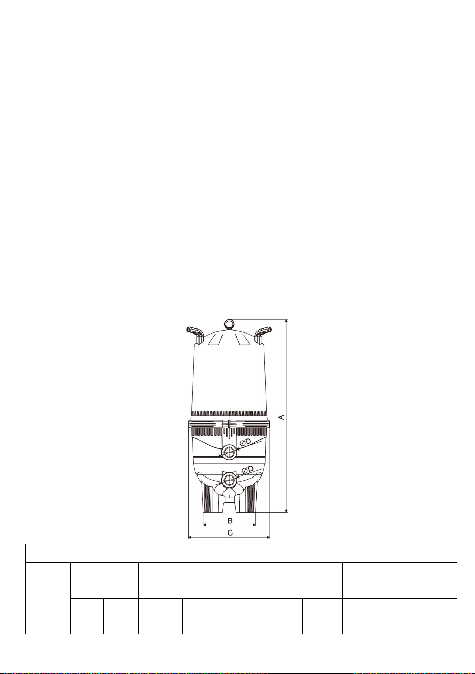
6
43) Zamontuj wkład(y) i rurę środkową tak, aby znajdowały się w dolnym
czopku.
44) Upewnij się, że uszczelka okrągła pokrywy filtra jest czysta, nasmarowana
smarem do uszczelek i znajduje się w dolnym rowku.
45) Załóż pokrywkę i mocno dociśnij. Dokręcić pierścień zabezpieczający,
wystarczy dokręcić ręką – NIE DOKRĘCAĆ PRZECIĘCIE.
46) Upewnij się, że pompa została zalana zgodnie ze wskazówkami
producenta.
47) Upewnić się, że wszystkie zawory na przewodach ssawnym i tłocznym są
otwarte.
48) Uruchom pompę.
49) Zamknąć zawór odpowietrzający, gdy całe powietrze zostanie usunięte.
SPECYFIKACJE
Dane techniczne filtra kasetowego
Model
Obszar filtra
Połącz rozmiar
Zalecany przepływ _
_ _
Maks. ciśnienie
robocze
Ft
2
m
2
Cal
mm
lpm
m
3
/godz
Bar

7
GL320
320
29,7
2
60
496,8
29,8
3
GL420
420
39
2
60
533,4
32
3
GL520
520
48.3
2
60
566,8
34
3
Model
A(mm)
B(mm)
C(mm)
ФD (cale)
GL320
1014
430
620
2
GL420
1169
430
620
2
GL520
1324
460
620
2
Cztery wkłady w kompaktowej obudowie
Filtry kasetowe GL320-520 zawierają cztery wkłady poliestrowe, które zatrzymują ogromne
ilości zanieczyszczeń, a jednocześnie są łatwe do czyszczenia. Połówki zbiornika
wzmocnione włóknem szklanym są zabezpieczone innowacyjnym pierścieniem
zaciskowym - wystarczy poluzować pierścień i zdjąć górną połowę, aby uzyskać łatwy
dostęp do wkładu i płukanie. Łatwiejsza konserwacja filtra
Ciągły wewnętrzny odpowietrznik zapobiega gromadzeniu się powietrza, zapewniając
maksymalną pracę filtra
wydajność.
Jednoczęściowa podstawa i korpus zapewniają wytrzymałość, stabilność i lata
niezawodnej pracy.
Rozwinięty schemat
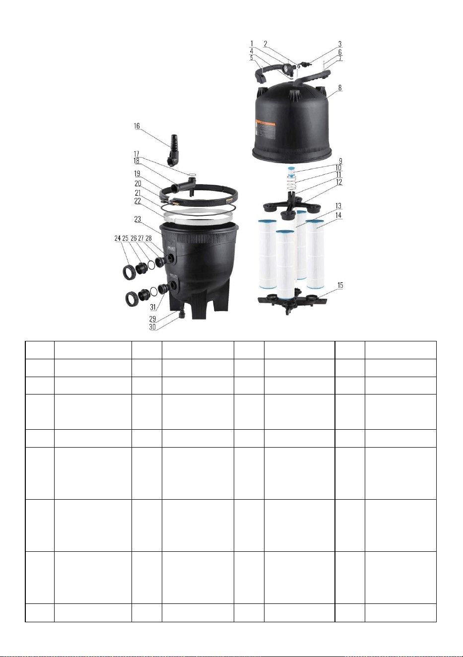
8
NIE.
OPIS
NIE.
OPIS
NIE.
OPIS
NIE.
OPIS
1
Ciśnieniomierz
9
Nabój
17
Pierścień O
25
Rura
2
Pierścień O
10
Wiosna
18
Podłącz rurę
26
Pierścień O
3
Zespół zaworu
11
Korek
spustowy
19
Zestaw opaski
zaciskowej
27
Adapter Unii 1
4
Pierścień O
12
Góra kolektora
20
Nut-Spl
28
Pierścień O
5
Uchwyt
13
Zespół
odpowietrznika
21
Zacisk
zbiornika
O-ring RPM
29
Pierścień O
6
Śruby
14
Nabój
22
Zespół
lokalizacji
30
Nakrętka
odciążająca
wodę
7
Pralka
15
Zespół
kolektora.
Spód
23
Dolna połowa
zbiornika
31
Adapter Unii 2
8
Zestaw górnej
16
Wlot
24
Orzech
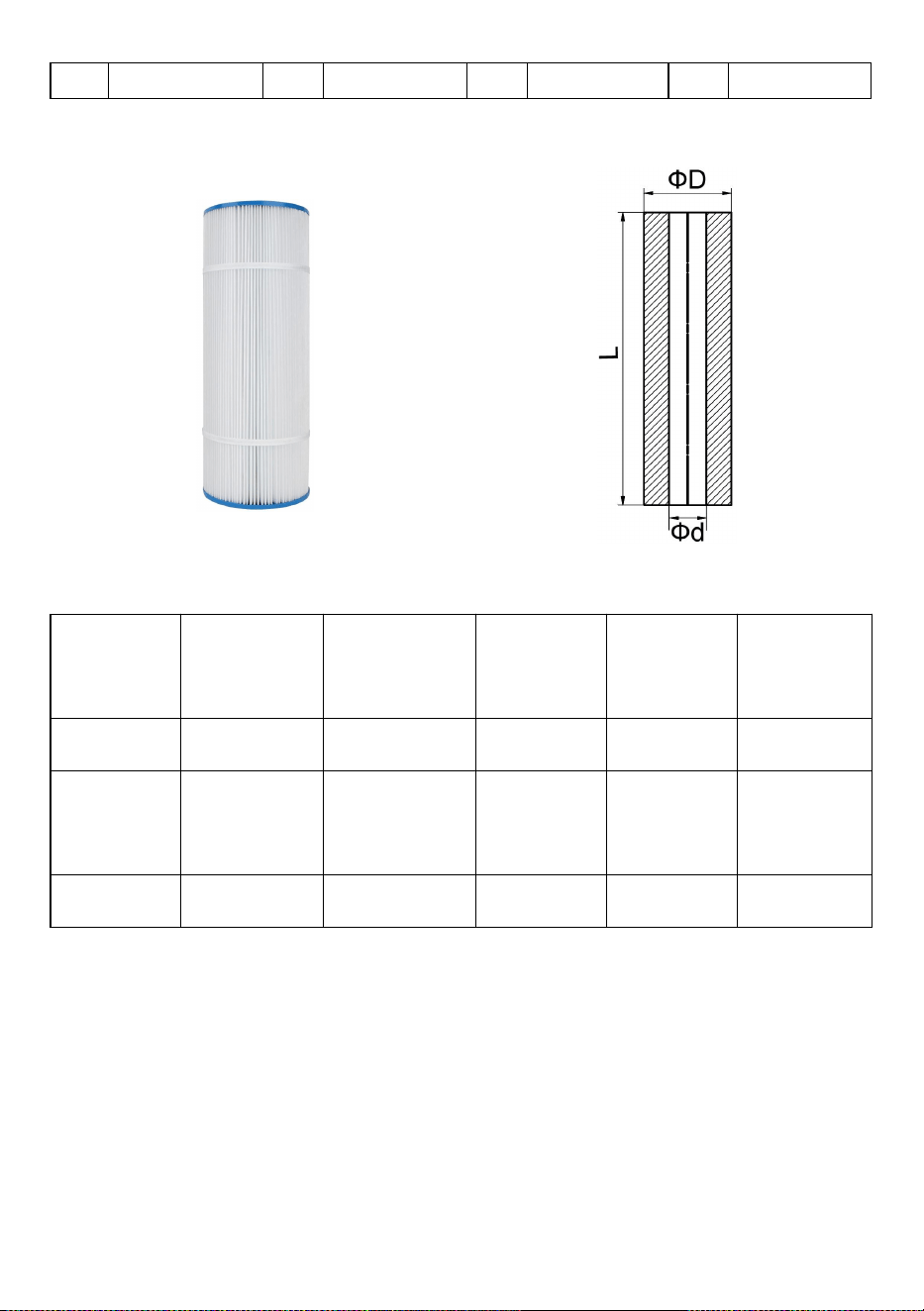
9
połowy zbiornika
Wkład filtra
Model
średnica
zewnętrzna
Wewnętrzna
średnica
Długość
Numer
Model
zastępczy
GL320 _
178 mm
76mm
508 mm
4
PLFPCC80
GL420 _
178 mm
76mm
660 mm
4
C-7488
GL520 _
178 mm
76mm
814 mm
4
TRF-7472
Łatwe do czyszczenia i wielokrotnego użytku elementy wkładów
Wkłady mają dodatkową zdolność zatrzymywania brudu i są wykonane z
trwałych, wysokiej jakości materiałów zapewniających dłuższą żywotność przy
minimalnej konserwacji. Po prostu wyjmij wkład i przepłucz wkład wodą z
węża lub wyczyść wkład środkiem do czyszczenia filtrów.
OGŁOSZENIE:

10
Po upływie okresu użytkowania wkładów filtrujących lub ich uszkodzeniu
użytkownik może zakupić inne elementy filtrujące o tym samym rozmiarze do
montażu.
OSTRZEŻENIE
△
!
Filtr ten działa pod wysokim ciśnieniem. Kiedy jakakolwiek część układu
obiegowego (np. zacisk, pompa, filtr, zawory itp.) jest serwisowana, powietrze
może przedostać się do układu i znaleźć się pod ciśnieniem. Powietrze pod
ciśnieniem może spowodować wydmuchanie pokrywy lub zaworu, co może
skutkować poważnymi obrażeniami, śmiercią lub uszkodzeniem mienia.
△
!
Przed zmianą położenia zaworu należy wyłączyć pompę.
△
!
Aby zapobiec uszkodzeniu pompy i zapewnić prawidłowe działanie
systemu, należy regularnie czyścić filtr siatkowy pompy i kosze skimmera.
Adres: Baoshanqu Shuangchenglu 803long 11hao 1602A-1609shi Szanghaj
Import do AUS: SIHAO PTY LTD . 1 ROKEVA STREETEASTWOOD NSW 2122 Australia
Import do USA: Sanven Technology Ltd. Apartament 250, 9166 Anaheim Place, Rancho
Cucamonga, Kalifornia 91730
REP
EC
SHUNSHUN GmbH
Römeräcker 9 Z2021,76351
Linkenheim-Hochstetten,Germany
REP
UK
Pooledas Group Ltd
Unit 5 Albert Edward House, The Pavilions
Preston, United Kingdom

11
Wyprodukowano w Chinach


Technisch Ondersteuning en e-garantiecertificaat www.vevor.com/support
PATROONZWEMBADFILTER HANDLEIDING
We continue to be committed to provide you tools with competitive price.
"Save Half", "Half Price" or any other similar expressions used by us only represents an
estimate of savings you might benefit from buying certain tools with us compared to the major
top brands and does not necessarily mean to cover all categories of tools offered by us. You
are kindly reminded to verify carefully when you are placing an order with us if you are
actually saving half in comparison with the top major brands.

1
Modellen: GL320, GL420, GL520
Have product questions? Need technical support? Please feel free to
contact us:
Technical Support and E-Warranty Certificate
www.vevor.com/support
NEED HELP? CONTACT US!
This is the original instruction, please read all manual instructions
carefully before operating. VEVOR reserves a clear interpretation of our
user manual. The appearance of the product shall be subject to the
product you received. Please forgive us that we won't inform you again if
there are any technology or software updates on our product.
CARTRIDGE POOL
FILTER

2
De installatie van dit product moet worden uitgevoerd door een persoon met
kennis van de loodgieterswerkvereisten voor zwembaden, waarbij de
installatie-instructies in deze handleiding moeten worden gevolgd. Geef deze
instructies door aan de eigenaar van dit apparaat.
PATROONFILTER
Gefeliciteerd met uw aankoop van een kwaliteitsproduct uit het assortiment
zwembad- en spa-apparatuur dat verkrijgbaar is bij pool systems. U bent
verzekerd van jarenlang betrouwbare en efficiënte prestaties .
Patroonfilters zijn speciaal ontworpen voor de filtratie van spa- en
zwembadwater. Ze mogen niet voor andere doeleinden worden gebruikt
zonder eerst uw dealer of zwembadsystemen te raadplegen.
Patroonfilters bieden zuinigheid, hoge prestaties en gemak in een goed
ontworpen drukfilter. Het polyesterelement kan snel worden verwijderd voor
spoelreiniging zonder waterverlies.
Patroonfilters hebben grote filteroppervlakken, die zorgen voor een
gelijkmatige waterverdeling, maximale filtratieprestaties en langere filtercycli.
De corrosiebestendige constructie van patroonfilters zorgt voor een lange
levensduur en duurzaamheid.
De capaciteit van patroonfilters is afgestemd op het assortiment zwembad- en
spa-pompen dat verkrijgbaar is bij zwembadsystemen, en vormt een totaal
zwembadfiltratiesysteem dat is gebouwd om lang mee te gaan. Zorg ervoor
dat u de pomp- en filtercapaciteiten op elkaar afstemt om een maximale winst
te behalen prestaties en efficiëntie.
PATROONFILTRATIEPROCES
Patroonfiltratie is een effectieve, probleemloze, bewezen filtratiemethode.
Zwembadwater komt het filter binnen en passeert een polyester patroon met
één element. Zwevende deeltjes worden opgevangen en het water wordt
teruggevoerd naar het zwembad. Naarmate de vuilophoping in het element
toeneemt, stijgt de waterdruk en neemt de doorstroming af. Wanneer de druk
een onaanvaardbaar niveau bereikt, moet het element worden verwijderd en

3
gereinigd (sproeien met een gewone tuinslang is over het algemeen
voldoende)
INSTALLATIE- EN BEDIENINGSINSTRUCTIES
PLAATS
Het filter moet op een permanente locatie worden geplaatst, bij voorkeur zo
dicht mogelijk bij het zwembad of de spa. Plaats de filtertank en pomp op een
vlakke betonplaat of een soortgelijke ondergrond. Zorg voor voldoende ruimte
rond het filter voor routineonderhoud en zorg voor voldoende ventilatie en
afvoer. Plaats de pomp op zijn plaats op de mat en plaats het filter naast de
juiste pompinlaataansluiting, gericht naar de pomp. Raadpleeg het hoofdstuk
'Specificaties' voor de minimale afstandsmetingen die voor elk model vereist
zijn.
WEERBESCHERMING
Patroonfilters zijn gemaakt van corrosiebestendige materialen. Om jarenlang
betrouwbare prestaties te garanderen, wordt echter aanbevolen het
filtersysteem voldoende te beschermen tegen weersinvloeden.
MONTAGE
Monteer de manometer op het filterdeksel met behulp van teflontape op de
buitenschroefdraad. Niet te vast aandraaien.
LEIDINGSAANSLUITINGEN
De leidingen moeten onafhankelijk worden ondersteund en mogen het filter of
de pomp niet zwaar belasten. Gebruik 40 mm of 50 mm PV C -leiding voor
pomp- en zwembadretourleidingen. Er moet altijd 50 mm worden gebruikt als
de leidinglengte groter is dan 15 mm. Patroonfilters worden geleverd met

4
snelkoppelingen die geschikt zijn voor 40 mm LDPVC-leidingen of fittingen
met een buitendiameter van 50 mm. Als de pomp en het filter zich onder het
waterniveau van het zwembad bevinden, is het noodzakelijk om afsluitkleppen
in de leiding tussen de pomp en het zwembad te plaatsen, en in de
retourleiding van het filter naar het zwembad.
15) Pomp om te filteren
Patroonfilters zijn uitgerust met twee inlaatpoorten gemarkeerd met 'INLET'.
Selecteer de inlaatpoort die het meest geschikt is voor de installatie en sluit de
andere inlaatpoort af met de meegeleverde afsluitdop. Sluit met behulp van
snelkoppelingen de aanvoerleiding van de zwembadpomp aan op de
geselecteerde inlaatpoortkoppelingen en sluit de aanvoerleiding van de
zwembadpomp aan op de geselecteerde inlaatpoort. Alleen met de hand
vastdraaien. Zorg ervoor dat het o'ringsmeermiddel zich in de juiste positie
bevindt.
16) Filter op poolretour
Sluit met behulp van snelkoppelingen de retourleiding van het zwembad aan
op de filterfitting gemarkeerd met 'OUTLET'. Draai de fitting alleen met de
hand vast. Zorg ervoor dat de o'ring op de fitting schoon is, gesmeerd met
o'ringsmeermiddel en in de juiste positie zit. De filterbasis is voorzien van vier
montagegaten, zodat deze indien nodig kan worden vastgezet.
FILTERWERKING
50) Zorg ervoor dat de pomp is gevuld volgens de aanwijzingen van de
fabrikant.
51) Zorg ervoor dat alle kleppen op de zuig- en persleidingen open zijn. Zorg
ervoor dat het ontluchtingsventiel op het filterdeksel open is en dat de sluitring
van het deksel op zijn plaats zit en goed vastzit.
52) Start de pomp. Sluit de ontluchtingsklep wanneer er water uitstroomt.
53) Om de juiste bedrijfsomstandigheden met een schoon filter te bepalen,
controleert u of de manometerwaarde 180 kpa of lager is.
54) Noteer de waarde van de manometer of markeer de naaldpositie op de
voorkant van de manometer.

5
55) Laat het filter lang genoeg werken om het totale zwembadwatervolume
dagelijks te laten circuleren. Het filter moet ook altijd in werking zijn als het
zwembad in gebruik is en gedurende ongeveer een uur daarna. Tijdens de
winter kan de looptijd worden verkort. De vereisten voor de werking van de
filters variëren voor spa-toepassingen. Afhankelijk van het systeemontwerp,
het type en de grootte van de spa. Raadpleeg uw bouwer of spa-leverancier.
56) Wanneer de manometerwaarde 180-230 kpa hoger is dan de 'schoon
filter'-waarde zoals in (4) hierboven, is het tijd om het cartridge-element
schoon te maken (zie' Cartridge-reinigingsprocedure).
CARTRIDGE REINIGINGSPROCEDURE
Wanneer de filtermeterwaarde 50-70 kpa boven de schone filtermeterwaarde
ligt, is reiniging van de cartridge met één element vereist. Om de
reinigingsprocedures uit te voeren
36) Schakel de pomp uit.
37) Sluit de afsluitkleppen op de zuig- en persleidingen, indien aanwezig.
38) Open het ontluchtingsventiel op het filterdeksel. schroef de borgring los en
verwijder het filterdeksel.
39) Til het patroonelement eruit.
40) In de meeste gevallen kan het element eenvoudig worden gereinigd met
een tuinslang, waarbij met goede snelheid rechtstreeks op de plooien wordt
gespoten.
OPMERKING
Algen, calcium, klei, zonnebrandolie en lichaamsoliën kunnen een coating op
het element vormen die mogelijk niet gemakkelijk kan worden verwijderd met
normaal afspuiten. Deze materialen kunnen worden verwijderd door het
element in een ontvetter en/of te weken ontkalker. Uw plaatselijke dealer kan u
geschikte producten aanbevelen.
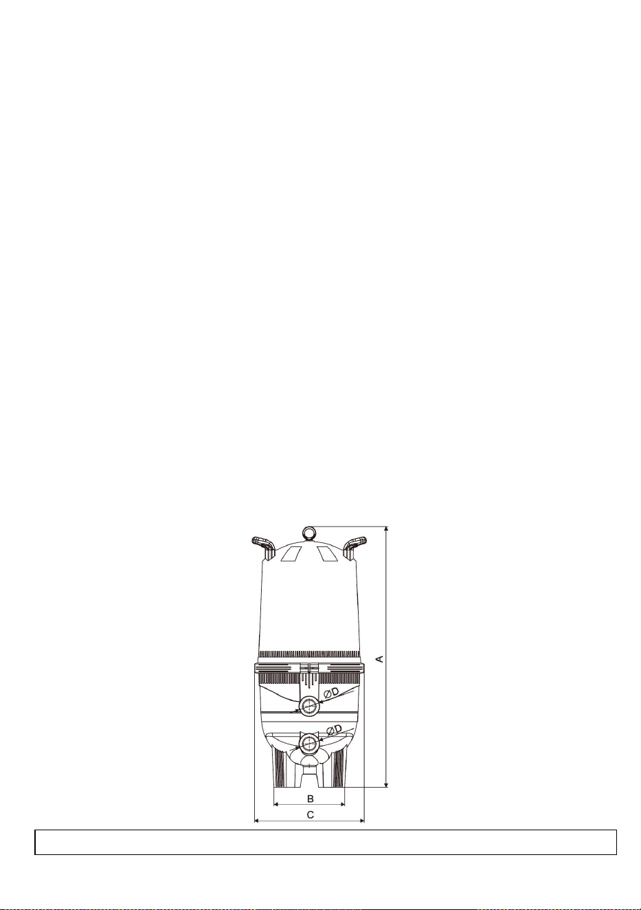
6
INSTRUCTIE VOOR HERMONTAGE VAN DE
CARTRIDGE
50) Installeer de cartridge(s) en de middenpijp zo dat deze zich in de onderste
aansluiting bevinden.
51) Zorg ervoor dat de o-ring van het filterdeksel schoon is, gesmeerd met
O-ring-smeermiddel en zich in de onderste groef bevindt.
52) Plaats het deksel terug en druk stevig op zijn plaats. Schroef de borgring
vast, handvast is voldoende - NIET TE VAST DRAAIEN.
53) Zorg ervoor dat de pomp is gevuld volgens de aanwijzingen van de
fabrikant.
54) Zorg ervoor dat alle kleppen op de zuig- en persleidingen open zijn.
55) Start de pomp.
56) Sluit de ontluchtingsklep wanneer alle lucht is verdreven.
SPECIFICATIES
Specificaties patroonfilter
7
Model
Filtergebied
Sluit maat aan
Aanbevolen stroom _
_ _
Max. werkdruk
Ft
2
m2
_
Duim
mm
lpm
m
3
/uur
Bar
GL320
320
29.7
2
60
496,8
29.8
3
GL420
420
39
2
60
533,4
32
3
GL520
520
48,3
2
60
566,8
34
3
Model
EEN(mm)
B(mm)
C(mm)
ФD(inch)
GL320
1014
430
620
2
GL420
1169
430
620
2
GL520
1324
460
620
2
Vier cartridges in een compact ontwerp
GL320-520 patroonfilters bevatten vier polyester patronen die enorme hoeveelheden vuil
vasthouden en toch gemakkelijk te reinigen zijn. De met glasvezel versterkte tankhelften
zijn vastgezet met een innovatieve klemring. Maak gewoon de ring los en verwijder de
bovenste helft voor gemakkelijke toegang tot de cartridges en spoelen. Filteronderhoud
eenvoudiger gemaakt
Continue interne ontluchting voorkomt luchtophoping, zodat het filter optimaal blijft werken
prestatie.
Basis en behuizing uit één stuk voor sterkte, stabiliteit en jarenlange betrouwbare service.
Uitgebreid diagram
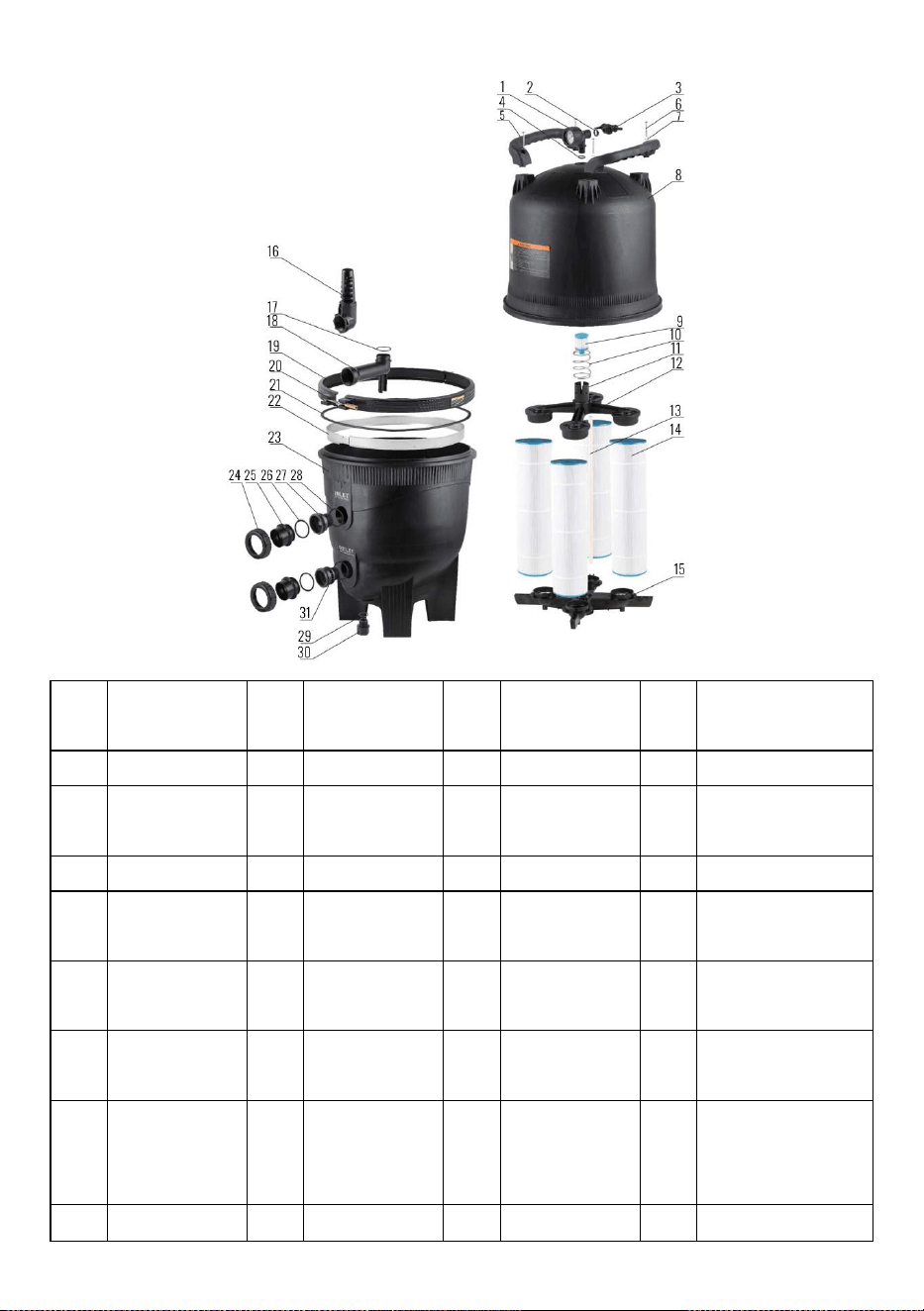
8
Nee
.
BESCHRIJVI
NG
Nee
.
BESCHRIJVI
NG
Nee
.
BESCHRIJVI
NG
Nee
.
BESCHRIJVING
1
Druk meter
9
Patroon
17
O-ring
25
Pijp
2
O-ring
10
Lente
18
Sluit de pijp
aan
26
O-ring
3
Klepmontage
11
Afvoerdop
19
Kit klemband
27
Union-adapter 1
4
O-ring
12
Spruitstuk
bovenaan
20
Moer-Spl
28
O-ring
5
Hendel
13
Ontluchter
Assy
21
O-ring
RPM-tankklem
29
O-ring
6
Schroeven
14
Patroon
22
Locatie band
30
Waterontlastingsm
oer
7
Wasmachine
15
Spruitstuk
Assy.
Onderkant
23
Tank-onderste
helft
31
Union-adapter 2
8
Tank-bovenste
16
Inlaat
24
Noot
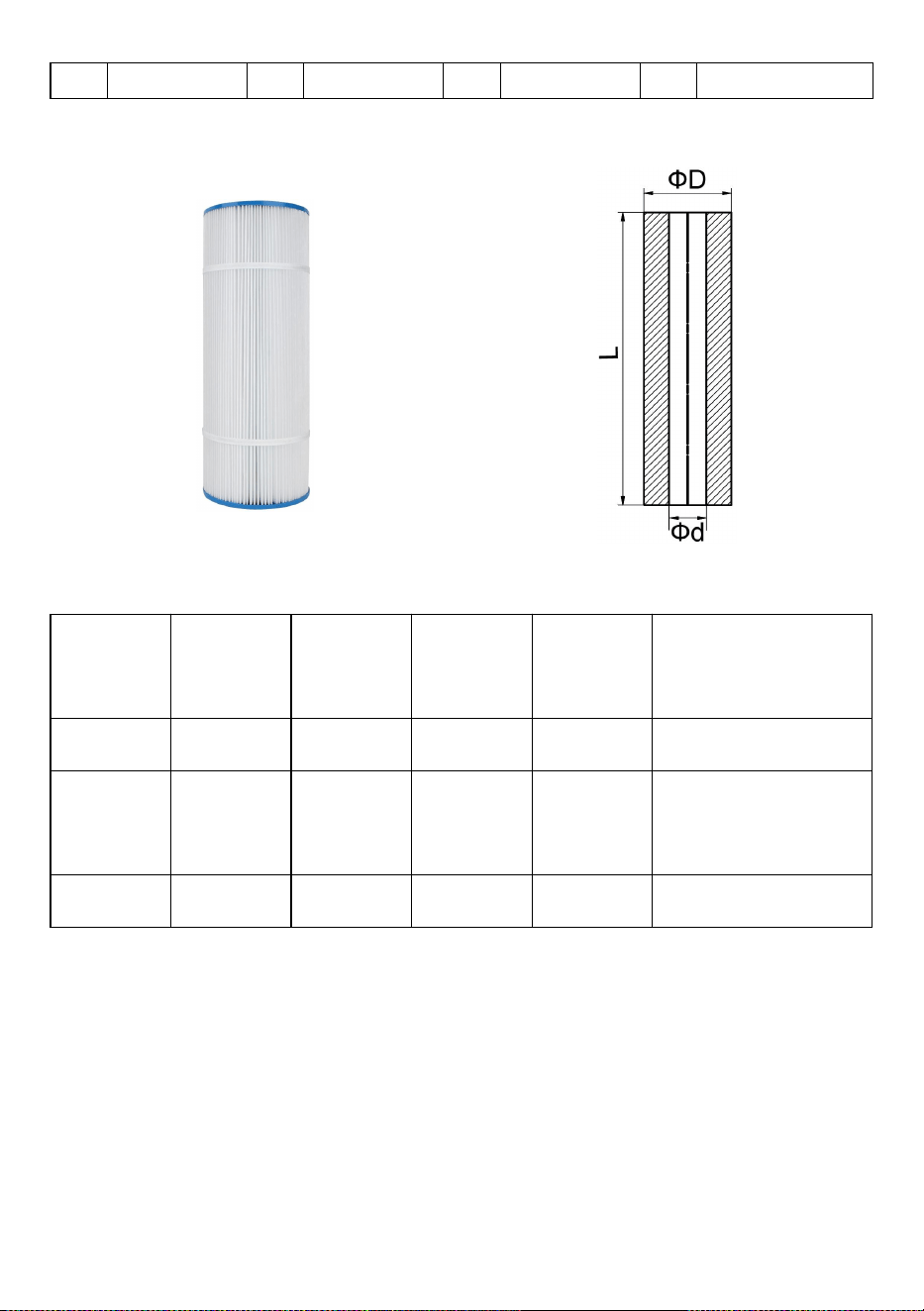
9
helftset
Filter vulling
Model
Externe
diameter
Interne
diameter
Lengte
Nummer
Vervangingsmodel
GL320 _
178 mm
76 mm
508 mm
4
PLFPCC80
GL420 _
178 mm
76 mm
660 mm
4
C-7488
GL520 _
178 mm
76 mm
814 mm
4
TRF-7472
Gemakkelijk schoon te maken en herbruikbare cartridge-elementen
Patronen hebben een extra vuilhoudend vermogen en zijn gemaakt van
duurzame, hoogwaardige materialen voor een langere levensduur met
minimaal onderhoud. Verwijder eenvoudig het patroonelement en spoel de
patroon door met slangwater of reinig de patroon met een filterreiniger.
KENNISGEVING:

10
Nadat de levensduur van de filterpatronen is verstreken of beschadigd is, kan
de gebruiker andere filterelementen van hetzelfde formaat aanschaffen voor
installatie.
WAARSCHUWING
△
!
Dit filter werkt onder hoge druk. Wanneer enig onderdeel van het
circulatiesysteem (bijv. klem, pomp, filter, kleppen, enz.) wordt onderhouden,
kan lucht het systeem binnendringen en onder druk komen te staan. Lucht
onder druk kan ertoe leiden dat het deksel of de klep wordt weggeblazen, wat
kan leiden tot ernstig letsel, de dood of schade aan eigendommen.
△
!
Schakel de pomp uit voordat u de kleppositie wijzigt.
△
!
Om schade aan de pomp te voorkomen en voor een goede werking van
het systeem, dient u de pompzeef en skimmermanden regelmatig schoon te
maken.
Adres: Baoshanqu Shuangchenglu 803long 11hao 1602A-1609shi Shanghai
Geïmporteerd naar AUS: SIHAO PTY LTD . 1 ROKEVA STREETEASTWOOD NSW 2122
Australië
Geïmporteerd naar de VS: Sanven Technology Ltd. Suite 250, 9166 Anaheim Place,
Rancho Cucamonga, CA 91730
REP
EC
SHUNSHUN GmbH
Römeräcker 9 Z2021,76351
Linkenheim-Hochstetten,Germany
REP
UK
Pooledas Group Ltd
Unit 5 Albert Edward House, The Pavilions
Preston, United Kingdom

11
Gemaakt in China