

1
40A PROFESSIONAL WHEELED BATTERY
CHARGER WITH 200A ENGINE START
INSTRUCTION MANUAL
CARGADOR DE BATERÍA 40A PROFESIONAL DE
RUEDAS CON 200A ARRANQUE DEL MOTOR
MANUAL DE INSTRUCCIÓN
SAVE THIS INSTRUCTION MANUAL FOR FUTURE REFERENCE.
CONSERVE ESTE MANUAL PARA FUTURAS CONSULTAS.
© 2023 Baccus Global LLC
Boca Raton, FL 33487
1-877-571-2391
BC200F
BC
English page 5
Español pagina 11
2
FEATURES
CARACTERÍSTICAS
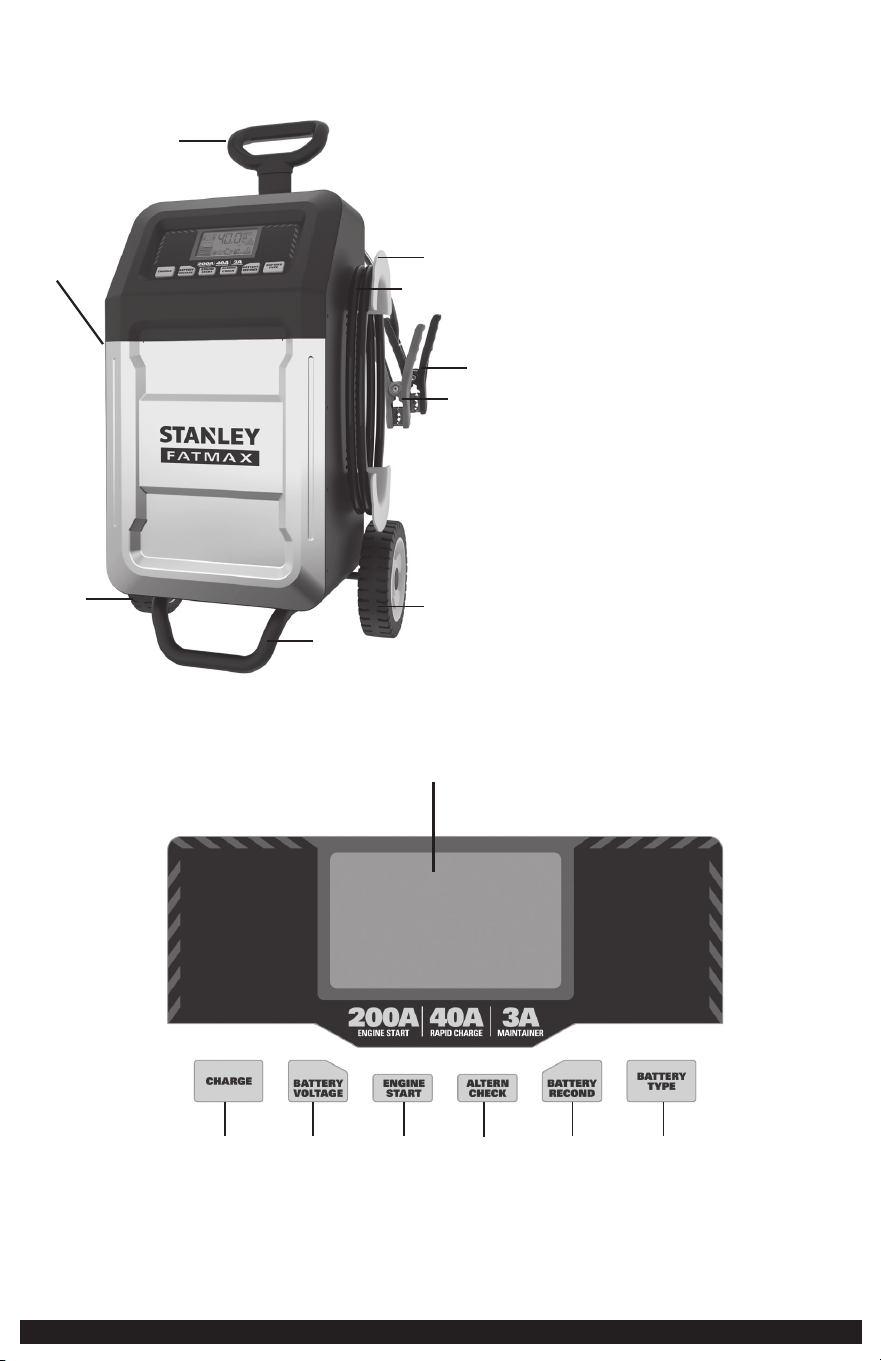
FEATURES:
1. Handle
2. Negative Clamp (black)
3. Positive Clamp (red)
4. 120 Volt AC Cable and Plug on Storage Spool (not shown)
5. Cable Storage Spool
6. Output Cable
7. Base Stand
8. Wheels (2 in total)
CARACTERÍSTICAS:
1. Mango
2. Abrazadera Negativa (negra)
3. Abrazadera Positiva (roja)
4. Cable de 120 Voltios CA y Enchufe en el Carrete de
Almacenamiento (no se muestra)
5. Carrete de Almacenamiento de Cables
6. Cable de Salida
7. Base de Soporte
8. Ruedas (2 en total)
1
3
2
4
6
5
7
8
8
9
10
11 12
13
14
15
9. LCD Screen 13. Alternator Check Button 9. Pantalla LCD 13. Botón de Verificación del Alternador
10. Battery Charge Button 14. Battery Recondition Button 10. Botón de Carga de la Batería 14. Botón de Reacondicionamiento de Batería
11. Battery Voltage Button 15. Battery Type Selector Button 11. Botón de Voltaje de la Batería 15. Botón Selector de Tipo de Batería
12. Engine Start Button 12. Botón de Arranque del Motor
3
LCD DISPLAY DETAIL
DETALLE DE LA PANTALLA LCD
FEATURES
CARACTERÍSTICAS
FEATURES:
1. Handle
2. Negative Clamp (black)
3. Positive Clamp (red)
4. 120 Volt AC Cable and Plug on Storage Spool (not shown)
5. Cable Storage Spool
6. Output Cable
7. Base Stand
8. Wheels (2 in total)
CARACTERÍSTICAS:
1. Mango
2. Abrazadera Negativa (negra)
3. Abrazadera Positiva (roja)
4. Cable de 120 Voltios CA y Enchufe en el Carrete de
Almacenamiento (no se muestra)
5. Carrete de Almacenamiento de Cables
6. Cable de Salida
7. Base de Soporte
8. Ruedas (2 en total)
24
26
1817
16
21
22
31
19
20
25
30 29 28 27
23
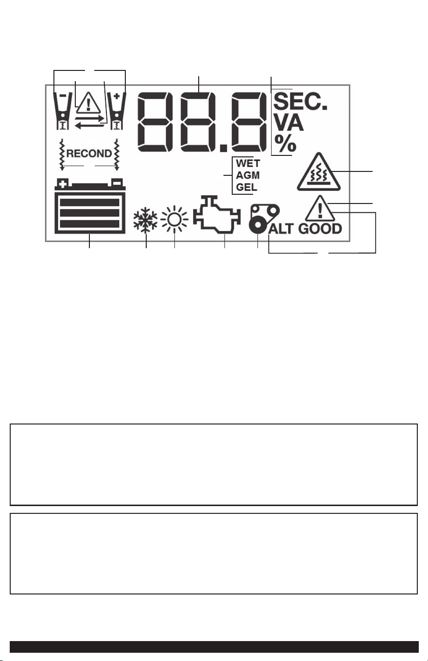
16. Clamp Icons
17. Alarm Icon
18. Reverse Polarity Icons
19. Digital Display (varies by function)
20. Seconds/Voltage/Ampere/Percentage Indicator
21. Battery Recondition Indicator
22. Battery Reconditioning Icons
23. Battery Type Indicator
24. Overheat Alarm Icon
25. Fault Icon
26. Alternator Good/Fault Indicators
27. Alternator Icon
28. Pump Engine Icon
29. High Temperature Compensation Icon
30. Low Temperature Compensation Icon
31. Battery Icon
16. Iconos de Abrazadera
17. Icono de Alarma
18. Íconos de Polaridad Inversa
19. Pantalla Digital (varía según la función)
20. Indicador de Segundos/Voltaje/Amperios/Porcentaje
21. Indicador de Reacondicionamiento de Batería
22. Íconos de Reacondicionamiento de Batería
23. Indicador de Tipo de Batería
24. Icono de Alarma de Sobrecalentamiento
25. Icono de Falla
26. Indicadores de Bueno/Fallo del Alternador
27. Icono del Alternador
28. Ícono del Motor de Bomba
29. Ícono de Compensación de Alta Temperatura
30. Ícono de Compensación de Baja Temperatura
31. Icono de Batería
This device complies with part 15 of the FCC rules. Operation is subject to the following two conditions: (1) this device may not cause harmful interference, and (2) this device must accept any interference received, including
interference that may cause undesired operation.
This unit has been tested and found to comply with the limits for a Class B digital device, pursuant to part 15 of the FCC Rules. These limits are designed to provide reasonable protection against harmful interference in a
residential installation. This unit generates, uses and can radiate radio frequency energy and, if not installed and used in accordance with the instructions, may cause harmful interference to radio communications. However, there
is no guarantee that interference will not occur in a particular installation. If unit does cause harmful interference to radio or television reception, which can be determined by turning the unit off and on, the user is encouraged
to try to correct the interference by one or more of the following measures:
• Reorient or relocate the receiving antenna.
• Increase the separation between unit and receiver.
• Connect the unit into an outlet on a circuit different from that to which the receiver is connected.
• Consult the dealer or an experienced radio/TV technician for help.
Changes or modifications not approved by the party responsible for compliance could void user’s authority to operate the unit.
Este dispositivo cumple con la parte 15 de las normas de la Comisión Federal de Comunicaciones de Estados Unidos (FCC). La operación está sujeta a las dos condiciones siguientes: (1) este dispositivo no puede causar interferencia
perjudicial y (2) este mecanismo debe aceptar cualquier interferencia recibida, incluida la in-terferencia que puede provocar una operación no deseada.
Este equipo ha sido probado y se encontró que cumple con los límites para dispositivo digital Clase B, según la parte 15 de las normas de la FCC. Estos límites están diseñados para brindar protección razonable contra
interferencia perjudicial en una instalación residencial. Este equipo genera, usa y puede irradiar energía en frecuencia de radio y, si no se instala y se usa de acuerdo con las instrucciones, puede provocar interferencia perjudicial
en las comunicaciones de radio. Sin embargo, no hay garantía de que la interferencia no ocurra en una instalación en particular. Si el equipo provoca interferencia perjudicial en la recepción de radio o televisión, lo que se puede
determinar al apagar y encender el equipo, el usuario debe tratar de corregir la interferencia mediante una o más de las siguientes medidas:
• Cambiar la orientación o la ubicación de la antena de recepción.
• Aumentar la separación entre el equipo y el receptor.
• Conectar el equipo a un tomacorriente sobre un circuito diferente de aquel al que está conectado el receptor.
• Consultar al vendedor o pedir la ayuda de un técnico en radio y televisión con experiencia.
Los cambios o las modificaciones no aprobados por el partido responsable de conformidad podían anular la autoridad del usuario para funcionar el equipo.
4
ASSEMBLING THE UNIT
BASE STAND AND WHEEL SET INSTALLATION
ASAMBLEA DE LA UNIDAD
INSTALACIÓN DEL SOPORTE DE BASE Y CONJUNTO
DE RUEDAS
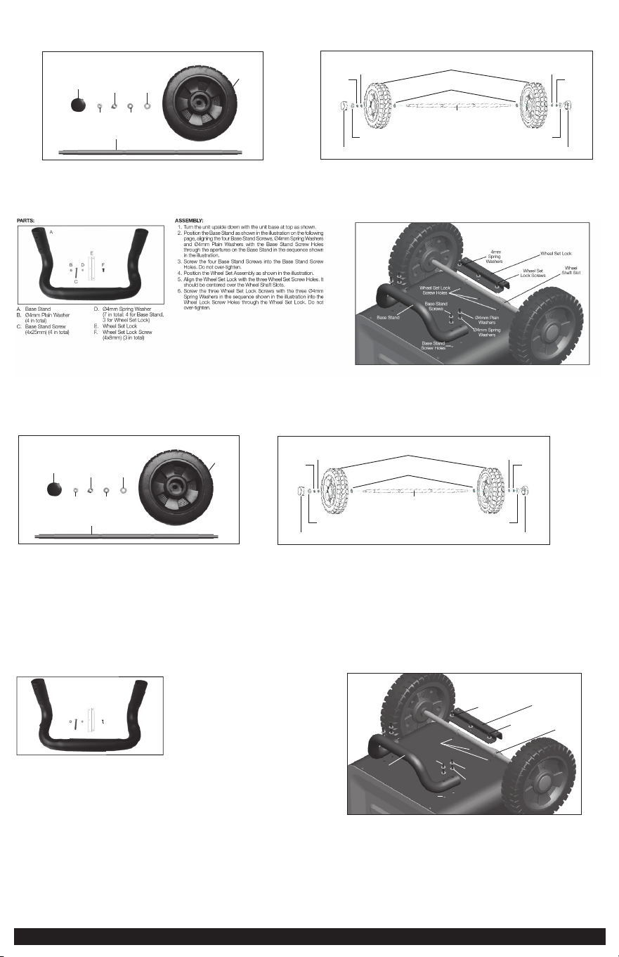
ASSEMBLY:
Ø8mm Plain Washers
Wheel Shaft
Wheels
Ø6mm
Spring
Washer
Wheel Nuts
Wheel Covers
Ø6mm
Plain
Washer
Ø6mm
Plain
Washer
Ø6mm
Spring
Washer
Wheel Nuts
Wheel Covers
1. Align one Wheel Set (Ø8mm Plain Washer, Wheel, Ø6mm Plain Washer, Ø6mm Spring Washer and Wheel Nut,
assembled in the sequence shown in the illustration) and attach to each end of the Wheel Shaft.
2. Screw the Wheel Nuts for each end of the Wheel Shaft.
3. Snap the Wheel Covers into the centre slot of each Wheel.
Assembling the Unit
Wheel Set Assembly
PARTS:
Wheel Shaft
Wheel Cover
(2 in total)
Wheel
Nut
(2 in total)
Ø6mm
Spring
Washer
(2 in total)
Ø6mm Plain
washer
(2 in total)
Ø8mm
Plain
washer
(2 in total)
Wheels
(2 in total)
Asamblea de la unidad
Asamblea del conjunto de ruedas
PARTES :
ÁRBOL DE LA RUEDA
CUBIERTA DE
LA RUEDA (2 en
total)
TUERCA DE LA
RUEDA
(2 en total)
Ø6mm
ARANDELA
DE MUELLE
(2 en total)
Ø6mm
ARANDELA
PLANA
(2 en total)
Ø8mm
ARANDELA
PLANA
(2 en total)
WHEELS
(2 in total)
ASAMBLEA:
Ø8mm arandelas planas
Árbol de rueda
Ruedas
Ø6mm
arandelas
de muelles
Tuerca de la rueda
Cubierta de la rueda
Ø6mm
arandela
plana
Ø6mm
arandela
plana
Ø6mm
arandelas
de muelles
Tuerca de la rueda
Cubierta de la rueda
1. Alinear uno conjunto de ruedas (Ø8mm arandela plana, rueda, Ø6mm arandela plana, Ø6mm arandela
de muelle and tuerca de la rueda, ensamblado en la secuencia mostrada en la ilustración) y adjuntar a cada
extremo del árbol de rueda.
2. Atornille las tuercas de la rueda para cada extremo del árbol de la rueda.
3. Encajar la cubiertas de la rueda en la ranura central de cada rueda.
PARTES :
A
B
C
D F
E
A. Soporte de la base
B. Ø4mm arandela básica
(4 en total)
C. Tornillo del soporte de la
base (4x25mm) (4 en total)
D. Ø4mm arandela de resorte
(7 en total: 4 para el soporte
de la base, 3 para el bloqueo
del conjunto de ruedas)
E.
Bloqueo del conjunto de
ruedas
F. Tornillo del
bloqueo del
conjunto de ruedas
(4x8mm)
(3 en total)
ASAMBLEA:
1. Gire la unidad boca abajo con la unidad base en la parte superior
como se muestra.
2. Colocar el soporte de la base como se muestra en la ilustración
de la página siguiente, alineando los cuatro tornillos de la base del
soporte, Ø4mm arandelas elástica
s y Ø4mm arandelas básicas
con la base del soporte con orificios para tornillos a través de las
aberturas en la base del soporte en la secuencia que se muestra
en la ilustración.
3. Atornillar los 4 tornillos del soporte de base enlos orificios de los
tornillos del soporte de base. No apretar en exceso.
4. Colocar el conjunto de la rueda como se
muestra en la ilustración.
5. Alinear el bloqueo del conjunto de las ruedas con los tres agujeros
de orificios de los tornillos de conjunto de las ruedas. Lo debe estar
centrado sobre las ranuras del conjunto de la ruedas.
6. Enroscar los tres tornillos del bloqueo del conjunto de ruedas
con
los tres Ø4mm arandelas de resorte en la secuencia que se muestra
en la ilustración en los orificios de bloqueo de la rueda de tornillo
a través del bloqueo del conjunto de la ruedas.
Bloqueo del conjunto de ruedas
Soporte
de la base
Ranuras del
conjunto de
la ruedas
Orificios de los tornillos
del conjunto de
bloqueo de ruedas
Ø4mm
arandelas
de resorte
Tornillos del
bloqueo del
conjunto de ruedas
Ø4mm
Arandelas básica
Tornillos del
soporte de la base
Orificios de los
tornillos del
soporte de la base
Ø4mm
Arandelas
de resorte
5
SAFETY
GUIDELINES /
DEFINITIONS
DANGER: Indicates an imminently hazardous situation which, if not avoided,
will result in death or serious injury.
WARNING: Indicates a potentially hazardous situation which, if not avoided,
may result in death or serious injury.
CAUTION: Indicates a potentially hazardous situation which, if not avoided,
may result in injury.
Used without the word, indicates a safety related message.
NOTICE: Indicates a practice not related to personal injury which, if not avoided,
may result in property damage.
RISK OF UNSAFE OPERATION. When using tools or equipment, basic safety
precautions should always be followed to reduce the risk of personal injury.
Improper operation, maintenance or modification of tools or equipment could
result in serious injury and property damage. There are certain applications for
which tools and equipment are designed. Manufacturer strongly recommends that
this product NOT be modified and/or used for any application other than for which
it was designed. Read and understand all warnings and operating instructions
before using any tool or equipment.
40A PROFESSIONAL WHEELED BATTERY CHARGER
W/200A ENGINE START
The BC200F 40A Professional Wheeled Battery Charger with 200A Engine Start is a
Stanley® FatMax® 40A battery charger that features 200 A engine start, alternator
check, and battery reconditioning functions.
IMPORTANT
SAFETY
INSTRUCTIONS
1. Keep these instructions.
2. Heed all warnings.
3. Follow all instructions.
4. Avoid dangerous environments. Don’t use battery chargers in damp or wet
locations. Do not use the charger in the rain or snow.
5. Clean only with a dry cloth.
6. Keep children away from the charging area. Keep the charger away from
children. This is not a toy!
7. Store indoors. When not in use, battery chargers should be stored indoors in dry,
and high or locked-up places – out of the reach of children.
8. Unplug the battery charger when not in use.
9. Stay alert. Use common sense. Do not operate this unit when you are
tired or impaired.
10. Only use attachments/accessories specified by the manufacturer.
11. Use only on a flat, level surface to avoid injury from tip-over.
12. Check for damaged parts. Dp not use if damaged in any way.
13. Unit shall not be exposed to dripping or splashing and no objects filled with
liquids, shall be placed on the unit.
NOTE: This unit has been tested and found to comply with the limits for a Class
B digital device, pursuant to Part 15 of the FCC Rules. These limits are designed
to provide reasonable protection against harmful interference in a residential
installation. This unit generates, uses and can radiate radio frequency energy and,
if not installed and used in accordance with the instructions, may cause harmful
interference to radio communications. However, there is no
guarantee that interference will not occur in a particular
installation. If this unit does cause harmful interference to radio
or television reception, which can be determined by turning
the unit off and on, the user is encouraged to try to correct the
interference by one or more of the following measures:
• Reorient or relocate the receiving antenna.
• Increase the separation between the unit and the receiver.
• Connect the unit into an outlet on a circuit different from that to which the
receiver is connected
• Consult the dealer or an experienced radio/TV technician for help.
Notice: Per FCC Part 15, changes or modifications to this unit not expressly
approved by Stanley could void your authority to operate this unit.
READ ALL
INSTRUCTIONS
WARNING: Read and understand this instruction manual before using this
unit. Failure to follow all instructions listed below may result in electric shock, fire
and/or serious injury.
SPECIFIC SAFETY INSTRUCTIONS FOR POWER
CORDS
• Don’t abuse the cord. Protect the power cord from being walked on or pinched
particularly at plugs, convenience receptacles, and the point where they exit from
the unit. Don’t abuse the power cord. Never carry the unit by cord or yank it to
disconnect from receptacle. Keep the cord from heat, oil, and sharp edges. Pull by
plug rather than cord when unplugging the unit.
• Ground fault circuit interrupter (GFCI) protection should be provided on the
circuits or outlets to be used. Receptacles are available having built in GFCI
protection and may be used for this measure of safety.
DANGER: Never alter 120 Volt AC Cable or plug provided. If it will not fit the
outlet, have a proper outlet installed by a qualified electrician. Improper connection
can result in a risk of an electric shock
EXTENSION CORDS
An extension cord should not be used unless absolutely necessary. Use of an
improper extension cord could result in a risk of fire and electric shock, and will
void warranty.
If an extension cord must be used, make sure your extension cord is in good
condition. When using an extension cord, be sure to use one heavy enough to
carry the current your product will draw. An undersized cord will cause a drop in
line voltage resulting in loss of power and overheating. The following table shows
the correct size to use depending on cord length and nameplate ampere rating. If
in doubt, use the next heavier gauge. The smaller the gauge number, the heavier
the cord.
Recommended Minimum AWG Size for Extension Cords
for Battery Chargers
AC Input Rating American Wire Gage (AWG) Size of Cord
Amperes Length of Cord, feet (m)
Equal to or But less
25 (7.6) 50 (15.2) 100 (30.5) 150 (45.6)
greater than than
0 2 18 18 18 16
2 3 18 18 16 14
3 4 18 18 16 14
4 5 18 18 14 12
5 6 18 16 14 12
6 8 18 16 12 10
8 10 18 14 12 10
10 12 16 14 10 8
12 14 16 12 10 8
14 16 16 12 10 8
16 18 14 12 8 8
18 20 14 12 8 6
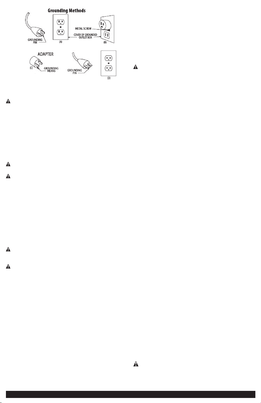
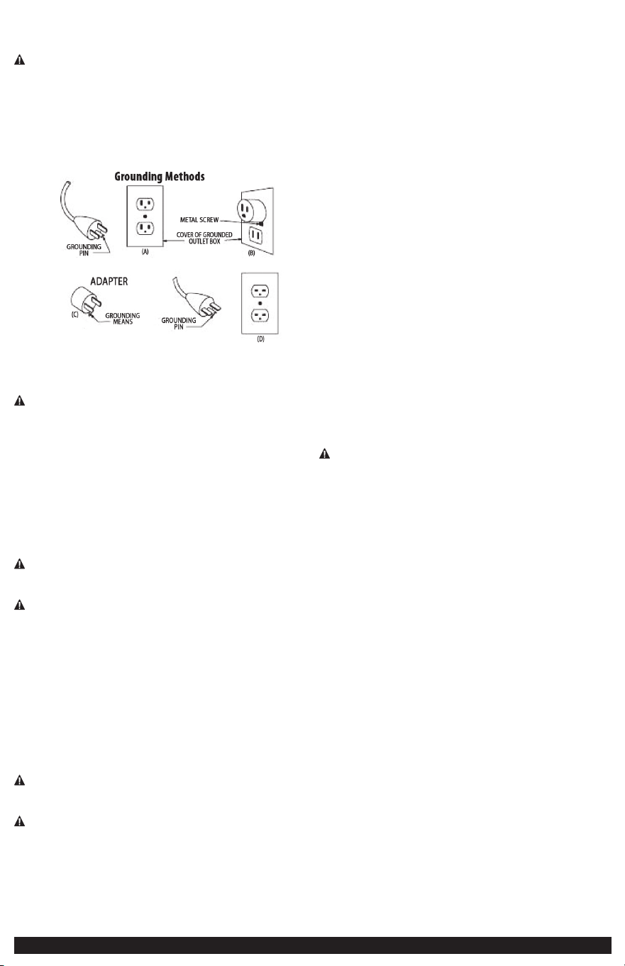
POWER CORD SAFETY
• The battery charger is for use on a nominal 120 volt circuit, and has a grounding
plug that looks like the plug illustrated in Figure A. A temporary adapter, which
looks like the plug illustrated in Figures B and C may be used to connect this plug
to a two-pole receptacle as shown in Figure B if a properly grounded outlet is not
available. The temporary adapter should be used only until a properly grounded
outlet can be installed by a qualified electrician.
DANGER: Before using an adapter as shown in the following illustration, be
certain that center screw of outlet plate is grounded. The green-colored rigid ear
or lug extending from adapter must be connected to a properly grounded outlet–
make certain it is grounded. If necessary, replace the original outlet cover plate
screw with a longer screw that will secure the adapter ear or lug to outlet cover
plate and make ground connection to a grounded outlet.
6
SPECIFIC SAFETY INSTRUCTIONS FOR
BATTERY CHARGERS
WARNING – BURST HAZARD - Do not use the unit for charging dry-cell
batteries that are commonly used with home appliances. These batteries may
burst and cause injury to persons and damage property. Use the unit for charging/
boosting a 12 volt lead-acid battery only. It is not intended to supply power to a
low-voltage electrical system other than in a starter-motor application.
• Use of accessories and attachments: The use of any accessory or attachment
not recommended by manufacturer for use with this battery charger could be
hazardous.
• Stay alert. Use common sense. Do not operate this unit when you are tired or
impaired.
• Do not operate the battery charger near flammable liquids or in gaseous or
explosive atmospheres. Motors may spark, and the sparks might ignite fumes.
WARNING – To reduce the risk of electric shock, never immerse the battery
charger in water or any other liquid, or use when wet.
WARNING – Risk of explosive gases:
• Working in the vicinity of a lead acid battery is dangerous. Batteries generate
explosive gases during normal battery operation. For this reason, it is of the
utmost importance that each time before using the battery charger you read this
manual and follow instructions exactly.
• To reduce the risk of battery explosion, follow these instructions and those
published by the battery manufacturer and manufacturer of any equipment you
intend to use in the vicinity of the battery. Review cautionary markings on these
products and on the engine.
• This unit employs parts (switches, relays, etc.) that produce arcs or sparks.
Therefore, if used in a garage or enclosed area, the unit MUST be placed not less
than 18 inches above the floor.
• THIS UNIT IS NOT FOR USE BY CHILDREN AND SHOULD ONLY BE OPERATED BY
ADULTS.
WARNING – To reduce the risk of fire:
• Do not operate near flammable materials, fumes, dust or gases.
• Do not expose to extreme heat or flames.
CAUTION – To reduce the risk of injury or property damage:
• NEVER ATTEMPT CHARGE A FROZEN BATTERY.
• Do not charge the battery while the engine is operating.
• Stay clear of fan blades, belts, pulleys, and other parts that can cause injury to
persons.
• Vehicles that have on-board computerized systems may be damaged if vehicle
battery is jump-started. Before jump-starting, read the vehicle’s owner’s manual to
confirm that external-starting assistance is suitable.
• When working with lead acid batteries, always make sure someone is close
enough to provide immediate assistance in case of accident or emergency.
• Always have protective eyewear when using this product: contact with battery acid
may cause blindness and/or severe burns. Be aware of first aid procedures in case
of accidental contact with battery acid.
• Have plenty of fresh water and soap nearby in case battery acid contacts skin.
• If battery acid contacts skin or clothing, wash immediately with soap and water for
at least 10 minutes and get medical attention immediately.
• Never smoke or allow a spark or flame in vicinity of vehicle battery, engine or
battery charger.
• Remove personal metal items such as rings, bracelets, necklaces and watches when
working with a lead acid battery. A lead acid battery can produce a short circuit
current high enough to weld a ring, or similar metal object, to skin causing a
severe burn.
• Be extra cautious to avoid dropping a metal tool onto the battery. It might spark
or short-circuit the battery or another electrical part, and that may cause an
explosion.
• Never allow battery acid to come in contact with this unit.
• Do not operate this unit in a closed area or restrict ventilation in any way.
• Always turn the battery charger off by unplugging it when not in use.
• Do not open the BATTERY CHARGER — there are no user-serviceable parts inside.
This unit is non-serviceable. Opening the battery charger will void manufacturer’s
warranty.
• Operate battery charger only as described in this Instruction Manual.
• Check battery charger and components periodically for wear and tear.
WARNING – To reduce the risk of injury, follow these instructions and those
published by the battery manufacturer and manufacturer of any equipment you
intend to use with this unit. Review cautionary markings on this product and on
engine.
FIRST AID
• Skin: if battery acid comes in contact with skin, rinse immediately with water, then
wash thoroughly with soap and water. If redness, pain, or irritation occurs, seek
immediate medical attention.
• Eyes: If battery acid comes in contact with eyes, flush eyes immediately, for a
minimum of 15 minutes and seek immediate medical attention.
• LCD liquid crystal display: If liquid crystal comes in contact with your skin: Wash
area off completely with plenty of water. Remove contaminated clothing. If liquid
crystal gets into your eye: Flush the affected eye with clean water and then seek
medical attention. If liquid crystal is swallowed: Flush your mouth thoroughly with
water. Drink large quantities of water and induce vomiting. Then seek medical
attention.
SAVE THESE
INSTRUCTIONS
PREPARING TO CHARGE
1. Be sure the area around battery is well ventilated while the battery is being
charged.
2. Remove the battery completely from a boat/airplane or any confined area
before charging.
3. If it is necessary to remove battery from a vehicle to charge or to clean
terminals, always remove the grounded terminal from the battery first. Make sure
all accessories in the vehicle are turned off, so as not to cause an electrical arc.
4. Clean the battery terminals, taking care to avoid getting corrosive material in
your eyes.
5. Add distilled water in each cell until battery acid reaches the level specified by
the battery manufacturer. This helps purge excessive gas from cells. Do not overfill.
For a battery without cell caps (maintenance free), carefully follow manufacturer’s
charging instructions.
6. Study all battery manufacturer’s specific precautions, such as removing or not
removing cell caps while charging, and recommended rates of charge.
7. Determine the voltage of the battery to be charged by referring to the vehicle
manual. This unit is for charging a 12 volt battery only.
CHARGER LOCATION
• IMPORTANT: Only use the unit on a flat, level surface to avoid movement during
operation. Take proper precautions to secure the wheels to avoid shifting or
movement before use.
• Locate the charger as far away from the battery as cables permit.
• Never place the charger directly above the battery being charged; gases from the
battery will corrode and damage the charger.
• Never allow battery acid to drip on the charger when reading gravity or filling
the battery.
• Never operate the charger in a closed-in area or restrict ventilation in any way.
• A marine (boat) battery must be removed and charged on shore.
• Do not set a battery on top of the charger.
CONNECTING THE CHARGER
CONNECTION PRECAUTIONS
• Connect and disconnect output clamps only after removing 120 Volt AC Cable
from electric outlet.
• Never allow the clamps to touch each other.
7
• Attach the clamps to the battery and chassis as indicated in the appropriate
section (“Follow these steps when the battery is installed in a vehicle” or “Follow
these steps when the battery has been removed from a vehicle”).
FOLLOW THESE STEPS WHEN THE BATTERY IS
INSTALLED IN A VEHICLE
WARNING – A spark near the battery may cause an explosion. To reduce risk
of a spark near the battery:
1. Do not charge the battery while the engine is operating.
2. Position AC and clamp cords to reduce risk of damage by hood, door, or moving
engine part.
3. Stay clear of fan blades, belts, pulleys, and other parts that can cause injury to
persons.
4. Check polarity of the battery posts. The positive post (marked POS, P, +) usually
has a larger diameter than the negative battery post (marked NEG, N, –).
5. Determine which post of battery is grounded (connected) to the chassis. If
negative post is grounded to chassis (as in most vehicles), see 6. If positive post is
grounded to the chassis, see 7.
6. For a negative-grounded vehicle, connect the Positive (red) Clamp from the
battery charger to the positive (POS, P, +) ungrounded post of battery. Connect the
Negative (black) Clamp to vehicle chassis or engine block away from battery. Do not
connect clip to carburetor, fuel lines, or sheet-metal body parts. Connect to heavy
gauge metal part of the frame or engine block.
7. For a positive-grounded vehicle, connect the Negative (black) Clamp from the
battery charger to the negative (NEG, N, –) ungrounded post of battery. Connect
Positive (red) Clamp to vehicle chassis or engine block away from battery. Do not
connect clip to carburetor, fuel lines or sheet-metal body parts. Connect to a heavy
gauge metal part of the frame or engine block.
8. See vehicle operating instructions or battery manual for length of charge
information.
9. When disconnecting charger, unplug the 120 Volt AC Cable, remove the clamp
from vehicle chassis, and then remove the clamp from the battery terminal.
FOLLOW THESE STEPS WHEN THE BATTERY HAS
BEEN REMOVED FROM A VEHICLE
WARNING – A spark near the battery may cause an explosion. To reduce risk
of a spark near the battery.
1. Check polarity of the battery posts. The positive post (marked POS, P, +) usually
has a larger diameter than the negative battery post (marked NEG, N, –).
2. Attach a 24-inch (minimum length) AWG #6 insulated battery cable to the
negative battery post (marked NEG, N, –).
3. Connect the Positive (red) Clamp to the positive battery post (red or marked
POS, P, +).
4. Stand as far back from the battery as possible, and do not face the battery when
making final connection.
5. Carefully connect the Negative (black) Clamp to the free end of the battery
cable connected to the negative terminal.
6. When disconnecting the charger, always do so in reverse sequence of connecting
procedure and break first connection while as far away from battery as practical.
NOTE: A marine (boat) battery must be removed and charged on shore. To charge it
on board requires equipment specifically designed for marine use. This unit is NOT
designed for such use.
Charging the Battery
IMPORTANT: If a problem is encountered during the battery charging process,
refer to the “Indications and Faults – All Modes” section that follows the battery
charging directions.
PROCEDURE
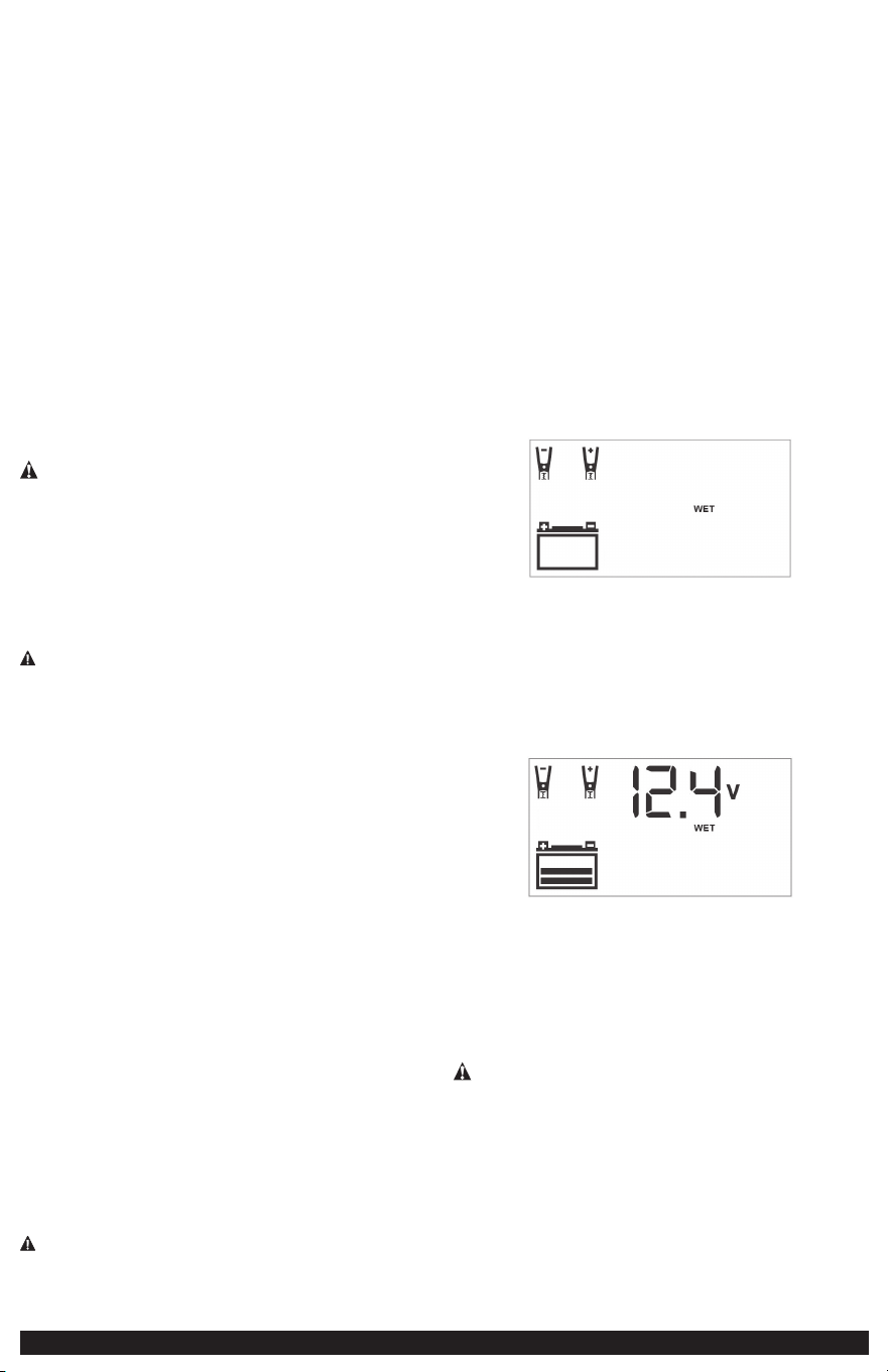
1. Plug the battery charger’s 120 Volt AC Cable into a functioning AC outlet. A
beep will sound and the LCD Screen will show the following:
The empty Battery Icon and Battery Type Indicator will light solid. The Clamp Icons
will flash to indicate the Battery Clamps are not yet connected to the battery.
2. Connect the battery charger to the battery using the battery clamps, following
the appropriate directions in the “Preparing to Charge” section at the front of
this Instruction Manual.
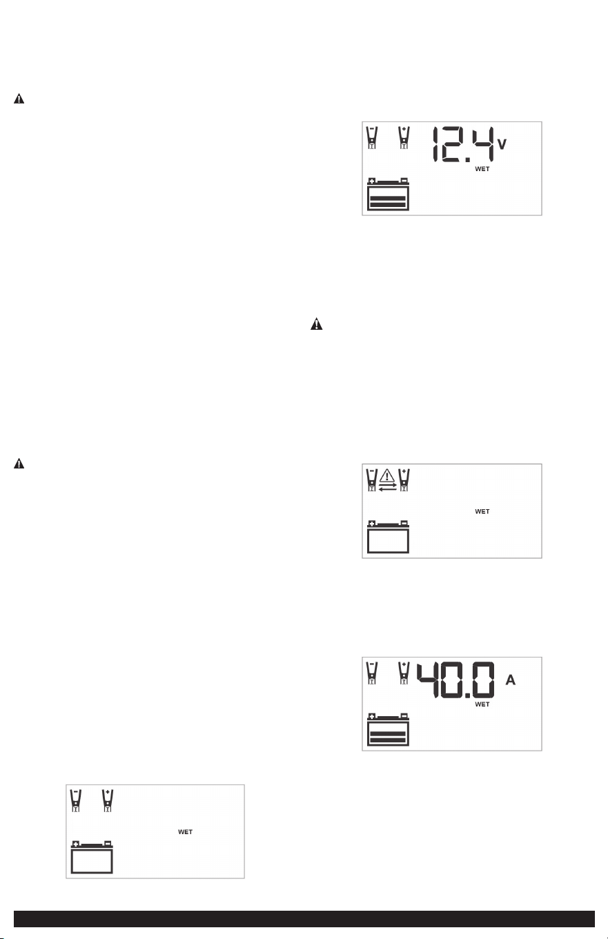
If the clamps are properly connected with regard to polarity, a beep will sound and
the LCD Screen will show the following, indicating the unit is in Standby Mode.
The Digital Display shows the voltage of the connected battery. The bars on the
Battery Icon represent the charge level of the connected battery. The Clamp Icons,
Battery Icon and the Battery Type Indicator light solid.
NOTES:
The charger allows you to select the appropriate battery type (WET, AGM or GEL)
for efficient and safe charging. The default selection is “WET” battery type. Press
the Battery Type Selector Button until the desired battery type indicator lights. A
beep will sound for each press of the button.
CAUTION – To reduce the risk of injury or property damage: Selecting an
incorrect battery type may adversely affect charging performance. Refer to the
battery manufacturer’s specifications to determine the battery type. Make this
selection BEFORE proceeding to the next step, as battery type cannot be selected
once charging has begun.
In Standby Mode, the Digital Display shows the voltage (V) of the connected battery
by default. Press the Battery Voltage Button once to show the charge status of
the battery as a percentage (%) of full. Pressing the Voltage Button cycles through
different standby status views of the connected battery.
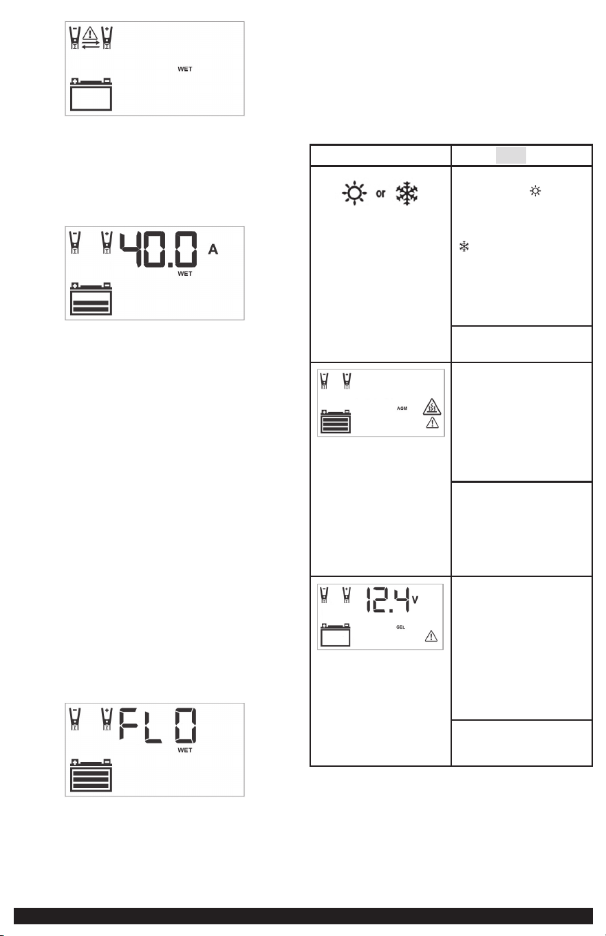
IMPORTANT: If the battery clamps are connected incorrectly with regard to polarity,
the LCD Screen shows the following:
The (empty) Battery Icon, the Battery Type Indicator and the Clamp Icons light
solid. The Alarm Icon, Reverse Polarity Icons, and the “+” and “–” signs on both
the Clamp Icons and the Battery Icon flash. The unit emits a continuous warning
sound until the clamps are disconnected. Remove the clamps and then reconnect
the clamps properly.
3. When the clamps are connected correctly, press the Battery Charge Button. The
LCD Screen will show the following:
The Digital Display shows the output current that is charging the battery. The
Clamp Icons and the Battery Type Indicator light solid and the bars on the Battery
Icon will change from empty to solid (bottom to top) to indicate the unit is in
Charging Mode.
NOTES:
A. The maximum output current is approximately 40A.
B. If the battery is already charged to nearly full capacity, the unit’s output
current may be automatically reduced despite the maximum output current
rating of 40A.
C. The charging process will start automatically approximately one minute after
the unit is properly connected to a battery if no other actions are taken.
8
D. The charging process can be terminated by pressing the Battery Charge Button
again to stop the function. The unit will revert to the Standby Mode. It will
automatically restart the charging process after approximately one minute if
no other actions are taken.
E. In Charging Mode, the Digital Display shows the output current (A) that is
charging the battery by default. Press the Battery Voltage Button once to show
the voltage (V) of the connected battery. Press the Battery Voltage Button
again to show the charge status of the battery as a percentage (%) of full.
Pressing the Voltage Button cycles through different charging status views of
the connected battery.
F. Once the unit is in Charging Mode, the Battery Type cannot be modified.
To change Battery Type, terminate the charging process and then reselect in
Standby Mode.
4. When the battery is completely charged, the unit automatically goes into Float
Charge Mode. In this mode, the unit monitors the battery voltage and charges as
necessary to assure the battery maintains a full charge. The unit remains in Float
Charge Mode as long as the charger is connected to the battery and plugged into a
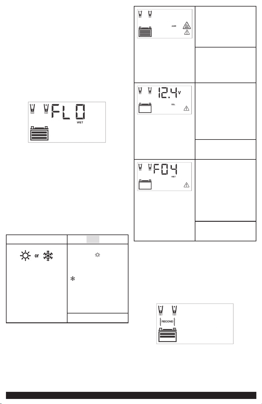
functioning AC outlet. The LCD Screen shows the following:
The Digital Display shows “FLO” indicating that the unit is in Float Charge Mode.
The Clamp Icons, the Battery Icon (with three bars), and the Battery Type Indicator
will light solid.
NOTE: In Float Charge Mode, the Digital Display shows “FLO” by default. Press the
Battery Voltage Button once to show the voltage (V) of the connected battery.
Press the Battery Voltage Button again to show the charge status of the battery
as a percentage (%) of full. Pressing the Voltage Button cycles through different
charging status views of the connected battery.
When the unit is in Float Charge Mode, the Battery Type cannot be modified. To
change Battery Type, terminate the charging process and then reselect in Standby
Mode.
5. When disconnecting the battery charger, unplug the 120 Volt AC Cable, remove
the clamp from the vehicle chassis, and then remove the clamp from the battery
terminal.
Indications and Faults – All Charging Modes
LCD Screen Shows: Indication | Solution:
Temperature compensation
activated: the “ ” icon will
appear if the surrounding
ambient temperature is higher
than approximately 40°c. The “
” icon will appear if the
surrounding ambient temperature
is lower than 0°c. This is not a
fault code, but indicates that the
unit’s temperature compensation
feature is operating.
No user action is required.
Overheat Protection Activated: If the
charger is overheated, the charging
process automatically terminates. The
Fault Icon and the Overheat Alarm
Icon flash. The Battery Icon, Clamp
Icons and the Battery Type Indicator
light solid.
Disconnect all battery charger
connections and allow the charger
to cool for several minutes. Make
sure there is adequate ventilation
around the unit before attempting to
charge again.
Battery Problem Detected: The
charger automatically checks the
battery condition 3 minutes after the
charging process starts. If the charger
detects a problem with a battery,
the charging process automatically
terminates. The Fault Icon and the
(empty) Battery Icon flash. The Clamp
Icons, the Battery Type Indicator and
the voltage of the connected battery.
Disconnect all battery charger
connections. Have the battery checked
by a qualified technician.
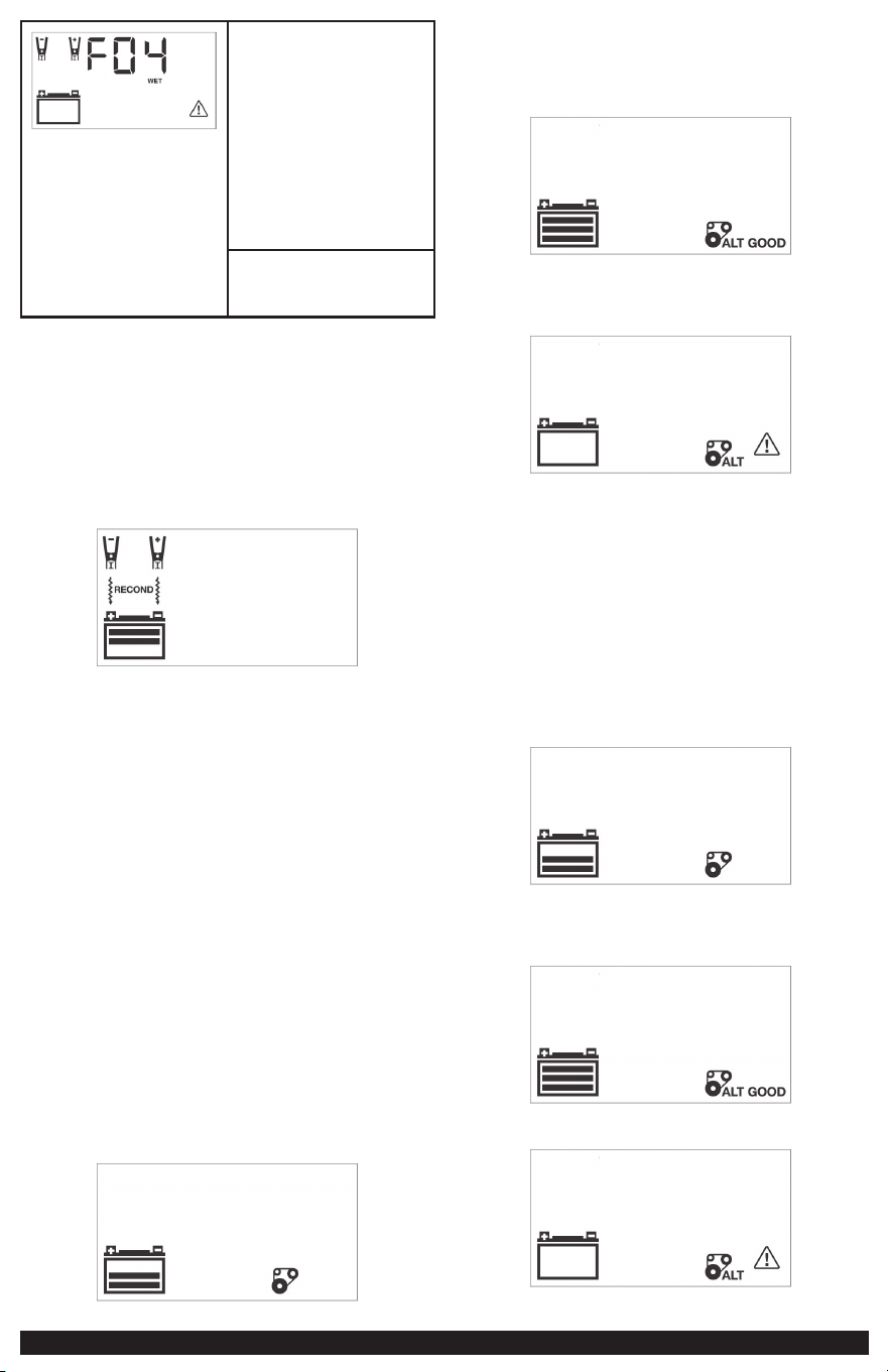
Possible Battery Problem Detected: If
the battery is not fully charged after
18 hours of continuous charging, the
battery may have internal damage
and will not accept a charge. After
18 hours, the charging process
automatically terminates. The Digital
Display shows “F04”, the Battery
Icon, the Clamp Icons and the Battery
Type Indicator light solid. The Fault
Icon flashes.
Disconnect all battery charger
connections. Have the battery checked
by a qualified technician.
Reconditioning the Battery
Periodic reconditioning is recommended to maintain a battery’s optimum
performance. Battery recondition sends a series of electrical pulses to break up
the crystalline form of lead sulfate and turn these chemicals into useful battery
electrolytes.
1. Refer to the “Charging the Battery” section of this Instruction Manual.
Set up the battery charger and connect to the battery following steps 1
and 2. The unit will be in Standby Mode.
2. Press the Battery Recondition Button once. A beep will sound and the
Digital Display will show the following
The Battery Recondition Indicator, the Clamp Icons and the Battery Icon light solid.
The Battery Recondition Icons flash, and the bars on the Battery Icon change from
solid to empty (top to bottom) repeatedly.
The process stops automatically after 24 hours. To end the process sooner, press the
Battery Recondition Button once again to turn it off. A beep will sound and the
unit will return to Standy Mode.
9
More than 24 hours may be needed to restore performance on some batteries. If
so, repeat the process.
3. When disconnecting the battery charger, unplug the 120 Volt AC Cable, and
then disconnect the battery charger from the battery following the last step of
the appropriate set of directions in the “Preparing to Charge” section of this
Instruction Manual.
IMPORTANT: If 5 cycles of reconditioning does not improve battery
performance, discontinue and recycle the battery.
Checking the Alternator
Part 1
No Load (turn OFF all vehicle’s accessories): The vehicle battery must be fully
charged before testing the alternator. Run the engine long enough to achieve
normal idle speed and verify there is a no-load voltage.
1. Refer to the “Charging the Battery” section of this Instruction Manual. Set up
the battery charger and connect to the battery following steps 1 and 2. The
unit will be in Standby Mode.
2. Press the Alternator Check Button to start the check. The Digital Display shows
the following to indicate the unit is analyzing the alternator:
The Alternator Icon will flash and the Battery icon with two bars will light solid.
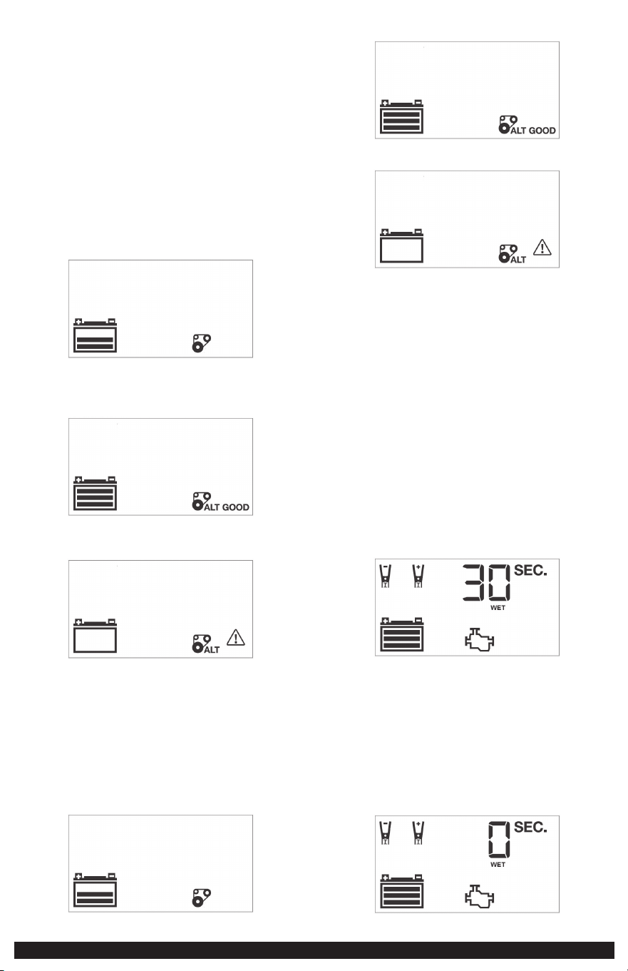
3. If the unit detects that the alternator is good, the LCD Screen shows the
following:
The Alternator Icon, “ALT GOOD” and the (full) Battery Icon will light solid.
4. If the unit detects that the alternator is out of typical voltage range, the LCD
Screen shows the following:
The Fault Icon will flash. The Alternator Icon, “ALT” and the (empty) Battery
Status Icon will light solid.
5. Press the Alternator Check Button again to stop the check.
Part 2
Under Load (accessories ON): Next, load the alternator by turning on as many
accessories as possible (except for the A/C and Defrost).
1. Refer to the “Charging the Battery” section of this Instruction Manual. Set up
the battery charger and connect to the battery following steps 1 and 2. The
unit will be in Standby Mode.
2. Press the Alternator Check Button to start the check. The Digital Display shows
the following to indicate the unit is analyzing the alternator:
The Alternator Icon will flash and the Battery icon with two bars will light solid.
3. If the unit detects that the alternator is good, the LCD Screen shows the
following:
4. If the unit detects that the alternator is out of typical voltage range, the LCD
Screen shows the following:
The Fault Icon will flash. The Alternator Icon, “ALT” and the (empty) Battery Status
Icon will light solid.
5. Press the Alternator Check Button again to stop the check.
6. When disconnecting the battery charger, unplug the 120 Volt AC Cable, and
then disconnect the battery charger from the battery following the last step of the
appropriate set of directions in the “Preparing to Charge” section of this Instruction
Manual.
Notes Concerning the Alternator Check Function:
A. IMPORTANT: This check may not be accurate for every make, manufacturer and
model of vehicle. Check only 12 volt systems.
B. The unit may detect that the alternator is out of typical voltage range because
someone has added a number of accessory loads on the charging system, thereby
increasing current demand from the alternator. MAKE SURE THAT THE ALTERNATOR
IS RATED TO SUPPORT THE APPLICATION.
Engine Start
1. Refer to the “Charging the Battery” section of this Instruction Manual. Set up
the battery charger and connect to the battery following steps 1 and 2. The unit
will be in Standby Mode.
2. Press the Engine Start Button once. A beep will sound and the LCD Screen shows
the following.
The Pump Engine Icon flashes. The Digital Display shows the countdown to indicate
the unit is in Engine Start Mode. The bars on the Battery Icon will change from
empty to solid (bottom to top) repeatedly. The Clamp Icons , the Battery Type
Indicator and the Battery Icon will light solid.
NOTES:
A. The Engine Start function may not be started if the battery charger detects that
the battery is at full capacity (fully charged).
B. The Engine Start countdown process can be terminated by pressing the Engine
Start Button again to stop the function.
3. When “0” is reached, a beep will sound and the LCD Screen will show the
following.

10
The Pump Engine Icon will light solid and the Digital Display shows “0 SEC” to
indicate the vehicle is ready to start. The Clamps Icon , the Battery Type Indicator
and the Battery Icon light solid. The bars on the Battery Icon will change from
empty to solid (bottom to top) repeatedly.
4. Crank the engine using manufacturer’s guidelines, typically in 3 to 5 second
bursts. The Digital Display shows “5 SEC” (a 5-second countdown to use as a timer
when cranking the engine).
5. After cranking, the unit will automatically adjust the charging current to about
3A for 5 minutes, and then revert to Charging Mode.
IMPORTANT: The Engine Start function requires a resting/cooling period between
attempts. Wait 4 to 5 minutes before a second attempt at starting the engine, if
needed.
6. When disconnecting the battery charger, unplug the 120 Volt AC Cable, and
then disconnect the battery charger from the battery following the last step of the
appropriate set of directions in the “Preparing to Charge” section of this Instruction
Manual:
CARE AND MAINTENANCE
WARNING: To reduce the risk of electric shock, unplug the battery charger
from the outlet before attempting any cleaning. Turning off the controls will not
reduce this risk.
Cleaning and Storage
Store the unit in a clean, dry, cool place when not in use.
Clean the unit casing and cords (as necessary) with a dry (or slightly damp) cloth.
Ensure that unit is completely disconnected from battery and power source before
cleaning.
To maintain the operating condition and maximize the life of the charger cords,
always coil them loosely on the built-in storage spool when not in use. Do not wrap
them around the unit or crimp them with a tight band.
TROUBLESHOOTING
Unit fails to turn on
• Check that the charger is properly connected to a live 120 volt AC outlet.
Unit fails to charge
• Check that the charger is properly connected to a live 120 volt AC outlet.
• If the battery to be charged has fallen below 2 volts, the battery may not be
recharged with this charger.
• Make sure a proper polarity cable connection has been established.
ACCESSORIES
WARNING: Since accessories, other than those offered by Stanley® FatMax®,
have not been tested with this product, use of such accessories with this unit could
be hazardous. To reduce the risk of injury, only Stanley® FatMax® recommended
accessories should be used with this product.
If you need assistance regarding accessories, please contact the manufacturer at
1-877-571-2391.
TECHNICAL ASSISTANCE
For Customer Service or Technical Assistance, contact the manufacturer at 1-877-
571-2391.
ONE-YEAR LIMITED MANUFACTURER’S WARRANTY
The manufacturer, Baccus Global LLC, warrants this product against defects in
materials and workmanship for a period of ONE (1) YEAR commencing from the
date of retail purchase by the original end-user purchaser or from the date of
delivery of the good, whichever occurs later (“Warranty Period”).
If there is a defect and a valid claim is received by the manufacturer within the
Warranty Period, the defective product can be replaced in the following ways: (1)
Return the product to the manufacturer for replacement. Proof of purchase may
be required by manufacturer. (2) Return the product to the retailer where product
was purchased for an exchange (provided that the store is a participating retailer).
Returns to retailer should be made within the time period of the retailer’s return
policy for exchanges only. Proof of purchase may be required. Please check with the
retailer for their specific return policy regarding returns that are beyond the time
set for exchanges.
This manufacturer’s warranty does not apply to accessories, bulbs, fuses and
batteries; defects resulting from normal wear and tear, accidents; damages sustained
during shipping; alterations; unauthorized use; neglect, misuse, abuse; and failure to
follow instructions for care and maintenance for the product.
This manufacturer’s warranty gives you, the original retail purchaser, specific legal
rights and you may have other rights which vary from state to state or province to
province. This product is not intended for commercial use. To register your product
with the manufacturer, please visit www.BaccusGlobal.com.
The photos in this manual may differ from the actual unit.
SPECIFICATIONS
Input: 120V AC, 60Hz, 660W
Output: 12V DC, 40A, 200A Engine Start (5 seconds ON, 5 minutes OFF)
STANLEY
®
AND THE STANLEY
®
LOGO ARE
REGISTERED TRADEMARKS OF STANLEY
BLACK + DECKER INC. OR ONE OF ITS AFFILIATES,
AND ARE USED UNDER LICENSE.
Imported by Baccus Global LLC,
621 NW 53rd St., Suite 450, Boca Raton, FL 33487
www.baccusglobal.com 1-877-571-2391
RD111223

11
INDICACIONES
DE SEGURIDAD /
DEFINICIONES
PELIGRO: Indica una situación de peligro inminente que, si no se evita,
provocará la muerte o lesiones graves.
ADVERTENCIA: Indica una situación potencialmente peligrosa que, si no se
evita, puede provocar la muerte o lesiones graves.
PRECAUCIÓN: Indica una situación potencialmente peligrosa que, si no se
evita, puede provocar lesiones.
Usado sin la palabra, indica un mensaje relacionado con la seguridad.
AVISO: Indica una práctica no relacionada con lesiones personales que, si no se
evita, puede provocar daños a la propiedad.
RIESGO DE OPERACIÓN INSEGURA. Al usar herramientas o equipos, siempre
se deben seguir precauciones básicas de seguridad para reducir el riesgo de lesiones
personales. La operación, el mantenimiento o la modificación inadecuados de
herramientas o equipos podrían provocar lesiones graves y daños a la propiedad.
Hay ciertas aplicaciones para las cuales las herramientas y equipos están diseñados.
El fabricante recomienda encarecidamente que este producto NO se modifique ni se
utilice para ninguna aplicación distinta para la que fue diseñado. Lea y comprenda
todas las advertencias e instrucciones de funcionamiento antes de utilizar cualquier
herramienta o equipo.
CARGADOR DE BATERÍA PROFESIONAL DE 40A
CON RUEDAS Y ARRANQUE DE MOTOR DE 200A
El Cargador de Batería Profesional con Ruedas BC200F de 40A y Arranque de
Motor de 200A es un cargador de batería Stanley® FatMax® de 40A que cuenta
con funciones de arranque del motor de 200 A, verificación del alternador y
reacondicionamiento de la batería.
INSTRUCCIONES
DE SEGURIDAD
IMPORTANTES
1. Guarde estas instrucciones.
2. Preste atención a todas las advertencias.
3. Siga todas las instrucciones.
4. Evite ambientes peligrosos. No utilice cargadores de baterías en lugares húmedos
o mojados. No utilice el cargador bajo la lluvia o la nieve.
5. Limpiar únicamente con un paño seco.
6. Mantenga a los niños alejados del área de carga. Mantenga el cargador fuera del
alcance de los niños. ¡Esto no es un juguete!
7. Almacenar en interiores. Cuando no estén en uso, los cargadores de baterías
deben almacenarse en interiores, en lugares secos, altos o cerrados con llave, fuera
del alcance de los niños.
8. Desenchufe el cargador de batería cuando no esté en uso.
9. Manténgase alerta. Use el sentido común. No opere esta unidad si no está
capacitado o cuando esté cansado.
10. Utilice únicamente aditamentos/accesorios especificados por el fabricante.
11. Úselo únicamente sobre una superficie plana y nivelada para evitar lesiones
por vuelco.
12. Verifique si hay piezas dañadas. No lo use si está dañado de alguna manera.
13. La unidad no deberá exponerse a goteos o salpicaduras y no se colocarán
objetos llenos de líquidos sobre la unidad.
NOTA: Esta unidad ha sido probada y cumple con los límites
para un dispositivo digital Clase B, de conformidad con la Parte
15 de las reglas de la Comisión Federal de Comunicaciones de
Estados Unidos (FCC por sus siglas en inglés). Estos límites están
diseñados para proporcionar una protección razonable contra
interferencias dañinas en una instalación residencial. Esta unidad genera, usa y
puede irradiar energía de radiofrecuencia y, si no se instala y usa de acuerdo con
las instrucciones, puede causar interferencias dañinas en las comunicaciones por
radio. Sin embargo, no hay garantía de que no se produzcan interferencias en una
instalación en particular. Si esta unidad causa interferencias dañinas en la recepción
de radio o televisión, lo cual se puede determinar apagando y encendiendo la
unidad, se recomienda al usuario que intente corregir la interferencia mediante una
o más de las siguientes medidas:
• Reoriente o reubique la antena receptora.
• Incremente la separación entre la unidad y el receptor.
• Conecte la unidad a una toma de corriente de un circuito diferente al que
está conectado el receptor
• Consulte al distribuidor o a un técnico experimentado en radio/TV para
obtener ayuda.
Aviso: Según la FCC Parte 15, los cambios o modificaciones a esta unidad que
no estén aprobados expresamente por Stanley podrían anular su autoridad para
operar esta unidad.
LEA TODAS LAS
INSTRUCCIONES
ADVERTENCIA: Lea y comprenda este manual de instrucciones antes de usar
esta unidad. No seguir todas las instrucciones enumeradas a continuación puede
provocar una descarga eléctrica, un incendio y/o lesiones graves.
INSTRUCCIONES DE SEGURIDAD ESPECÍFICAS PARA
CABLES DE ALIMENTACIÓN
• No abuse del cable. Proteja el cable de alimentación para que no lo pisen ni lo
dañen, particularmente en los enchufes, receptáculos y el punto desde donde salen
de la unidad. No abuse del cable de alimentación. Nunca transporte la unidad
por el cable ni tire de ella para desconectarla del receptáculo. Mantenga el cable
alejado del calor, el aceite y los bordes afilados. Tire por el enchufe en lugar de
por el cable cuando desenchufe la unidad.
• Se debe proporcionar protección con un interruptor de circuito de falla a tierra
(GFCI) en los circuitos o tomacorrientes que se utilizarán. Hay receptáculos
disponibles que tienen protección GFCI incorporada y pueden usarse para esta
medida de seguridad.
PELIGRO: Nunca altere el cable de 120 voltios CA ni el enchufe proporcionado.
Si no encaja en el tomacorriente, haga que un electricista calificado instale un
tomacorriente adecuado. Una conexión incorrecta puede provocar riesgo de
descarga eléctrica
CABLES DE EXTENSIÓN
No se debe utilizar un cable de extensión a menos que sea absolutamente
necesario. El uso de un cable de extensión inadecuado podría generar riesgo de
incendio y descarga eléctrica, y anulará la garantía.
Si se debe utilizar un cable de extensión, asegúrese de que esté en buenas
condiciones. Cuando utilice un cable de extensión, asegúrese de utilizar uno lo
suficientemente robusto como para transportar la corriente que consumirá su
producto. Un cable de capacidad insuficiente provocará una caída en el voltaje de la
línea, lo que provocará pérdida de energía y sobrecalentamiento. La siguiente tabla
muestra el tamaño correcto a utilizar según la longitud del cable y el amperaje
nominal de la placa de identificación. En caso de duda, utilice el siguiente calibre
más pesado. Cuanto menor sea el número de calibre, más robusto será el cable.
Tamaño Mínimo Recomendado AWG para Cables de
Extensión para Cargadores de Baterías
Entrada de CA Rating Calibre de Cable Americano (AWG) Tamaño y
Amperios Longitud de Cable, pies (m)
Igual o Pero menos
25 (7.6) 50 (15.2) 100 (30.5) 150 (45.6)
mayor que que
0 2 18 18 18 16
2 3 18 18 16 14
3 4 18 18 16 14
4 5 18 18 14 12
5 6 18 16 14 12
6 8 18 16 12 10
8 10 18 14 12 10
10 12 16 14 10 8
12 14 16 12 10 8
14 16 16 12 10 8
16 18 14 12 8 8
18 20 14 12 8 6
SEGURIDAD DEL CABLE DE ALIMENTACIÓN
• El cargador de batería es para uso en un circuito nominal de 120 voltios y tiene
un enchufe de conexión a tierra que se parece al enchufe ilustrado en la Figura
A. Se puede usar un adaptador temporal, que se parece al enchufe ilustrado en
las Figuras B y C, para conectar este enchufe a un receptáculo bipolar como se
12
muestra en la Figura B si no hay disponible un tomacorriente con conexión a
tierra adecuado. El adaptador temporal debe usarse sólo hasta que un electricista
calificado pueda instalar un tomacorriente con conexión a tierra adecuado.
PELIGRO: Antes de usar un adaptador como se muestra en la siguiente
ilustración, asegúrese de que el tornillo central de la placa de salida esté conectado
a tierra. La oreja o terminal rígido de color verde que se extiende desde el
adaptador debe conectarse a un tomacorriente con conexión a tierra adecuado;
asegúrese de que esté conectado a tierra. Si es necesario, reemplace el tornillo
original de la placa de la cubierta del tomacorriente con un tornillo más largo
que asegurará la oreja o lengüeta del adaptador a la placa de la cubierta del
tomacorriente y establecerá la conexión a tierra a un tomacorriente adecuado.
INSTRUCCIONES DE SEGURIDAD ESPECÍFICAS PARA
CARGADORES DE BATERÍAS
ADVERTENCIA – PELIGRO DE EXPLOSIÓN - No utilice la unidad para cargar
baterías de celda seca que se usan comúnmente con electrodomésticos. Estas
baterías pueden explotar y causar lesiones a personas y daños a la propiedad.
Utilice la unidad para cargar/reforzar una batería de plomo-ácido de 12 voltios
únicamente. No está destinada a suministrar energía a un sistema eléctrico de bajo
voltaje que no sea una aplicación de motor de arranque.
• Uso de accesorios y aditamentos: El uso de cualquier accesorio o aditamento no
recomendado por el fabricante para este cargador de batería podría ser peligroso.
• Manténgase alerta. Use el sentido común. No opere esta unidad si no está
capacitado o cuando esté cansado.
• No opere el cargador de baterías cerca de líquidos inflamables o en atmósferas
gaseosas o explosivas. Los motores pueden producir chispas y las chispas pueden
encender los gases.
ADVERTENCIA – Para reducir el riesgo de descarga eléctrica, nunca sumerja
el cargador de batería en agua ni en ningún otro líquido, ni lo utilice cuando el
lugar esté mojado.
ADVERTENCIA – Riesgo de gases inflamables:
• Es peligroso trabajar cerca de una batería de plomo-ácido. Las baterías generan
gases inflamables durante el funcionamiento normal de la batería. Por esta razón,
es de suma importancia que cada vez que utilice el cargador de batería lea este
manual y siga exactamente las instrucciones.
• Para reducir el riesgo de explosión de la batería, siga estas instrucciones y las
publicadas por el fabricante de la batería y el fabricante de cualquier equipo que
desee utilizar cerca de la batería. Revise las indicaciones de precaución en estos
productos y en el motor.
• Esta unidad emplea piezas (interruptores, relés, etc.) que producen arcos o chispas.
Por lo tanto, si se usa en un garaje o área cerrada, la unidad DEBE colocarse a no
menos de 18 pulgadas sobre el piso.
• ESTA UNIDAD NO DEBE SER USADA POR NIÑOS Y SÓLO DEBE SER OPERADA POR
ADULTOS.
ADVERTENCIA – Para reducir el riesgo de incendio:
• No opere cerca de materiales inflamables, vapores, polvo o gases.
• No exponga a calor extremo o llamas.
PRECAUCIÓN – Para reducir el riesgo de lesiones o daños a la propiedad:
• NUNCA INTENTE CARGAR UNA BATERÍA CONGELADA.
• No cargue la batería mientras el motor esté en funcionamiento.
• Manténgase alejado de las aspas del ventilador, correas, poleas y otras piezas que
puedan causar lesiones a las personas.
• Los vehículos que tienen sistemas computarizados a bordo pueden sufrir daños
cuando la batería del vehículo es auxiliada. Antes del arranque auxiliar, lea el
manual del propietario del vehículo para confirmar que la asistencia de arranque
externa es la apropiada.
• Cuando trabaje con baterías de plomo-ácido, asegúrese siempre de que haya
alguien lo suficientemente cerca para brindar asistencia inmediata en caso de
accidente o emergencia.
• Utilice siempre gafas protectoras cuando utilice este producto: el contacto con
el ácido de la batería puede provocar ceguera y/o quemaduras graves. Tenga en
cuenta los procedimientos de primeros auxilios en caso de contacto accidental con
el ácido de la batería.
• Tenga a mano abundante agua fresca y jabón en caso de que el ácido de la
batería entre en contacto con la piel.
• Si el ácido de la batería entra en contacto con la piel o la ropa, lávese
inmediatamente con agua y jabón durante al menos 10 minutos y busque atención
médica de inmediato.
• Nunca fume ni permita que haya chispas o llamas cerca de la batería del vehículo,
del motor o del cargador de batería.
• Quítese los artículos metálicos personales como anillos, pulseras, collares y relojes
cuando trabaje con una batería de plomo-ácido. Una batería de plomo-ácido
puede producir una corriente de cortocircuito lo suficientemente alta como
para derretir un anillo u objeto metálico similar sobre la piel, provocando una
quemadura grave.
• Tenga mucho cuidado y evite dejar caer una herramienta metálica sobre la batería.
Podría producir chispas o provocar un cortocircuito en la batería u otra pieza
eléctrica, lo que podría provocar una explosión.
• Nunca permita que el ácido de la batería entre en contacto con esta unidad.
• No opere esta unidad en un área cerrada ni restrinja la ventilación de ninguna
manera.
• Apague siempre el cargador de batería desenchufándolo cuando no esté en uso.
• No abra el CARGADOR DE BATERÍA; en su interior no hay piezas que el usuario
pueda reparar. Esta unidad no es reparable. Abrir el cargador de batería anulará la
garantía del fabricante.
• Utilice el cargador de batería únicamente como se describe en este Manual de
Instrucciones.
• Revise periódicamente el cargador de batería y los componentes para detectar
desgaste.
ADVERTENCIA – para reducir el riesgo de lesiones, siga estas instrucciones
y las publicadas por el fabricante de la batería y el fabricante de cualquier equipo
que desee utilizar con esta unidad. Revise las indicaciones de precaución en este
producto y en el motor.
PRIMEROS AUXILIOS
• Piel: si el ácido de la batería entra en contacto con la piel, enjuáguela
inmediatamente con agua y luego lávela minuciosamente con agua y jabón. Si se
produce enrojecimiento, dolor o irritación, busque atención médica inmediata.
• Ojos: Si el ácido de la batería entra en contacto con los ojos, enjuáguelos
inmediatamente durante un mínimo de 15 minutos y busque atención médica
inmediata.
• Pantalla LCD de cristal líquido: Si el cristal líquido entra en contacto con su piel:
Lave completamente el área con abundante agua. Quitar la ropa contaminada. Si
el cristal líquido entra en contacto con los ojos: enjuague el ojo afectado con agua
limpia y luego busque atención médica. Si se ingiere cristal líquido: Enjuáguese
bien la boca con agua. Beba grandes cantidades de agua e induzca el vómito.
Luego busque atención médica.
GUARDE ESTAS
INSTRUCCIONES
PREPARACIÓN PARA LA CARGA
1. Asegúrese de que el área alrededor de la batería esté bien ventilada mientras se
carga la batería.
2. Retire completamente la batería de un barco/avión o de cualquier área confinada
antes de cargarla.
3. Si es necesario retirar la batería de un vehículo para cargarla o limpiar los
terminales, siempre retire primero el terminal con conexión a tierra de la batería.
Asegúrese de que todos los accesorios del vehículo estén apagados para no provocar
un arco eléctrico.
4. Limpie los terminales de la batería, teniendo cuidado de evitar que le entre
material corrosivo en los ojos
.
13
5. Agregue agua destilada en cada celda hasta que el ácido de la batería alcance
el nivel especificado por el fabricante de la batería. Esto ayuda a purgar el exceso
de gas de las células. No llene demasiado. Para una batería sin tapas de celda (sin
mantenimiento), siga cuidadosamente las instrucciones de carga del fabricante.
6. Estudie todas las precauciones específicas del fabricante de la batería, como quitar
o no las tapas de las celdas durante la carga, y las tasas de carga recomendadas.
7. Determine el voltaje de la batería que se va a cargar consultando el manual del
vehículo. Esta unidad es sólo para cargar una batería de 12 voltios.
UBICACIÓN DEL CARGADOR
• IMPORTANTE: Utilice la unidad únicamente sobre una superficie plana y nivelada
para evitar movimientos durante el funcionamiento. Antes de usar, tome las
precauciones adecuadas para asegurar las ruedas y evitar desplazamientos o
movimientos.
• Ubique el cargador tan lejos de la batería como lo permitan los cables.
• Nunca coloque el cargador directamente encima de la batería que se está
cargando; Los gases de la batería corroerán y dañarán el cargador.
• Nunca permita que el ácido de la batería gotee sobre el cargador al leer la
gravedad o al llenar la batería.
• Nunca opere el cargador en un área cerrada ni restrinja la ventilación de ninguna
manera.
• Una batería marina (embarcación) debe retirarse y cargarse en tierra.
• No coloque una batería encima del cargador.
CONECTANDO EL CARGADOR
PRECAUCIONES DE CONEXIÓN
• Conecte y desconecte las abrazaderas de salida sólo después de retirar el cable de
120 voltios CA del tomacorriente eléctrico.
• Nunca permita que las abrazaderas se toquen entre sí.
• Fije las abrazaderas a la batería y al chasis como se indica en la sección
correspondiente (“Siga estos pasos cuando la batería esté instalada en un
vehículo” o “Siga estos pasos cuando la batería se haya retirado de un vehículo”).
SIGA ESTOS PASOS CUANDO LA BATERÍA ESTÉ
INSTALADA EN UN VEHÍCULO
ADVERTENCIA – una chispa cerca de la batería puede provocar una
explosión. Para reducir el riesgo de que se produzca una chispa cerca de la batería:
1. No cargue la batería mientras el motor esté en funcionamiento.
2. Coloque CA y los cables de las abrazaderas para reducir el riesgo de daños
causados por el capó, la puerta o la pieza móvil del motor.
3. Manténgase alejado de las aspas del ventilador, correas, poleas y otras piezas que
puedan causar lesiones a las personas.
4. Verifique la polaridad de los bornes de la batería. El borne positivo (marcado POS,
P, +) suele tener un diámetro mayor que el borne negativo (marcado NEG, N, –).
5. Determine cual borne de la batería está conectado a tierra (conectado) al chasis.
Si el borne negativo está conectado a tierra al chasis (como en la mayoría de los
vehículos), consulte 6. Si el poste positivo está conectado a tierra al chasis, consulte 7.
6. Para un vehículo con conexión a tierra negativa, conecte la Abrazadera Positiva
(roja) del cargador de batería al borne positivo (POS, P, +) sin conexión a tierra de la
batería. Conecte la Abrazadera Negativa (negra) al chasis del vehículo o al bloque
del motor lejos de la batería. No conecte la abrazadera al carburador, a las líneas de
combustible ni a las piezas de la carrocería. Conéctelo a una parte metálica de gran
calibre del bastidor o del bloque del motor.
7. Para un vehículo con conexión a tierra positiva, conecte la Abrazadera Negativa
(negra) del cargador de batería al borne negativo (NEG, N, –) sin conexión a tierra
de la batería. Conecte la Abrazadera Positiva (roja) al chasis del vehículo o al bloque
del motor lejos de la batería. No conecte la abrazadera al carburador, a las líneas de
combustible ni a las piezas de la carrocería. Conéctelo a una parte metálica de gran
calibre del bastidor o del bloque del motor.
8. Consulte las instrucciones de funcionamiento del vehículo o el manual de la
batería para más información sobre la duración de la carga.
9. Al desconectar el cargador, desenchufe el cable de 120 voltios CA, retire la
abrazadera del chasis del vehículo y luego retire la abrazadera del terminal de la
batería.
SIGA ESTOS PASOS CUANDO SE HAYA QUITADO LA
BATERÍA DE UN VEHÍCULO
ADVERTENCIA – : una chispa cerca de la batería puede provocar una
explosión. Para reducir el riesgo de que se produzca una chispa cerca de la batería.
1. Verifique la polaridad de los bornes de la batería. El borne positivo (marcado POS,
P, +) suele tener un diámetro mayor que el borne negativo (marcado NEG, N, –).
2. Conecte un cable de batería aislado AWG #6 de 24 pulgadas (longitud mínima) al
borne negativo de la batería (marcado NEG, N, –).
3. Conecte la Abrazadera Positiva (roja) al borne positivo de la batería (rojo o
marcado POS, P, +).
4. Colóquese lo más lejos posible de la batería y no mire hacia la batería cuando
realice la conexión final.
5. Conecte con cuidado la Abrazadera Negativa (negra) al extremo libre del cable de
la batería conectado al terminal negativo.
6. Al desconectar el cargador, hágalo siempre en secuencia inversa al procedimiento
de conexión y corte la primera conexión estando lo más lejos posible de la batería.
NOTA: La batería marina (de barco) debe retirarse y cargarse en tierra firme. Para
cargarlo a bordo se requiere de equipos diseñados específicamente para uso marino.
Esta unidad NO está diseñada para tal uso.
Cargando la Batería
IMPORTANTE: Si se encuentra un problema durante el proceso de carga de la
batería, consulte la sección “Indicaciones y fallas - Todos los modos” que sigue las
instrucciones de carga de la batería.
PROCEDIMIENTO
1. Conecte el cable de CA de 120 voltios del cargador de batería a un
tomacorriente de CA que funcione. Sonará un pitido y la pantalla LCD mostrará
lo siguiente:
El Icono de Batería Vacía y el Indicador de Tipo de Batería se iluminarán de forma
fija. Los Íconos de las Abrazaderas parpadearán para indicar que las Abrazaderas de
la Batería aún no están conectadas a la batería.
2. Conecte el cargador de batería a la batería usando las abrazaderas de la
batería, siguiendo las instrucciones apropiadas en la sección “Preparación para
Cargar” al principio de este Manual de Instrucciones.
Si las abrazaderas están conectadas correctamente según la polaridad, sonará un
pitido y la Pantalla LCD mostrará lo siguiente, indicando que la unidad está en
Modo de Espera.
La Pantalla Digital muestra el voltaje de la batería conectada. Las barras en el Ícono
de la Batería representan el nivel de carga de la batería conectada. Los Íconos de
Abrazadera, el Ícono de Batería y el Indicador de Tipo de Batería se iluminan de
manera fija.
NOTAS:
El cargador le permite seleccionar el tipo de batería apropiado (WET, AGM o GEL)
para una carga eficiente y segura. La selección predeterminada de batería es “WET”.
Presione el Botón Selector de Tipo de Batería hasta que se encienda el indicador del
tipo de batería deseada. Sonará un pitido por cada pulsación del botón.
PRECAUCIÓN – para reducir el riesgo de lesiones o daños a la propiedad:
Seleccionar un tipo de batería incorrecto puede afectar negativamente el
rendimiento de la carga. Consulte las especificaciones del fabricante de la batería
para determinar el tipo de batería. Haga esta selección ANTES de continuar con el
siguiente paso ya que no se puede cambiar el tipo de batería una vez comenzada la
carga.
En Modo de Espera, la Pantalla Digital muestra el voltaje (V) de la batería conectada
de forma predeterminada. Presione el Botón de Voltaje de la Batería una vez para
mostrar el estatus de carga de la batería como porcentaje (%) del total. Al presionar
el Botón de Voltaje, se revisan diferentes vistas del estatus del Espera de la batería
conectada.
IMPORTANTE: Si las abrazaderas de la batería están conectadas incorrectamente
según la polaridad, la pantalla LCD muestra lo siguiente:
14
El Ícono de Batería (vacía), el Indicador de Tipo de Batería y los Iconos de
Abrazadera se iluminan de forma fija. El Icono de Alarma, los Íconos de Polaridad
Inversa y los signos “+” y “–” tanto en los Íconos de Abrazadera como en el Ícono
de Batería parpadean. La unidad emite un sonido de advertencia continuo hasta
que se desconectan las abrazaderas. Retire las abrazaderas y vuelva a conectarlas
correctamente.
3. Cuando las abrazaderas estén conectadas correctamente, presione el Botón de
Carga de la Batería. La pantalla LCD mostrará lo siguiente:
La Pantalla Digital muestra la corriente de salida que está cargando la batería. Los
Íconos de Abrazadera y el Indicador de Tipo de Batería se iluminan fijos, así como
las barras de la Batería. El icono cambiará de vacío a sólido (de abajo hacia arriba)
para indicar que la unidad está en modo de carga
NOTAS:
A. La corriente de salida máxima es de aproximadamente 40A.
B. Si la batería ya está cargada casi a su capacidad total, la corriente de salida
de la unidad puede reducirse automáticamente a pesar de la clasificación de
corriente de salida máxima de 40A.
C. Si no se toman otras acciones, el proceso de carga comenzará automáticamente
aproximadamente un minuto después de que la unidad esté conectada
correctamente a una batería.
D. El proceso de carga se puede finalizar presionando nuevamente el Botón de
Carga de la Batería para detener la función. La unidad volverá al Modo de
Espera. Si no se toman otras acciones, reiniciará automáticamente el proceso de
carga después de aproximadamente un minuto.
E. En el Modo de Carga, la Pantalla Digital muestra la corriente de salida (A) que
carga la batería de forma predeterminada. Presione el Botón de Voltaje de la
Batería una vez para mostrar el voltaje (V) de la batería conectada. Presione
nuevamente el Botón de Voltaje de la Batería para mostrar el estado de carga
de la batería como porcentaje (%) del total. Al presionar el Botón de Voltaje,
se pasa por diferentes vistas del estatus de carga de la batería conectada.
F. Una vez que la unidad está en Modo de Carga, el tipo de batería no se puede
modificar. Para cambiar el Tipo de Batería, finalice el proceso de carga y luego
vuelva a seleccionarla en el Modo de Espera.
4. Cuando la batería está completamente cargada, la unidad pasa automáticamente
al Modo de Carga Flotante. En este modo, la unidad monitorea el voltaje de la
batería y carga según sea necesario para asegurar que la batería mantenga una
carga completa. La unidad permanece en Modo de Carga Flotante siempre que el
cargador esté conectado a la batería y enchufado a una toma de CA que funcione.
La Pantalla LCD muestra lo siguiente:
La pantalla digital muestra “FLO”, lo que indica que la unidad está en Modo de
Carga Flotante. Los Íconos de Abrazadera, el Ícono de Batería (con tres barras) y el
Indicador de Tipo de Batería se iluminarán de manera fija.
NOTA: En el Modo de Carga Flotante, la Pantalla Digital muestra “FLO” de forma
predeterminada. Presione el Botón de Voltaje de la Batería una vez para mostrar el
voltaje (V) de la batería conectada. Presione nuevamente el Botón de Voltaje de la
Batería para mostrar el estado de carga de la batería como porcentaje (%) del total.
Al presionar el Botón de Voltaje, se pasa por diferentes vistas del estatus de carga
de la batería conectada.
Cuando la unidad está en Modo de Carga Flotante, el Tipo de Batería no se puede
modificar. Para cambiar el Tipo de Batería, finalice el proceso de carga y luego
vuelva a seleccionarla en Modo de Espera.
5. Al desconectar el cargador de batería, desenchufe el cable de 120 voltios CA,
retire la abrazadera del chasis del vehículo y luego retire la abrazadera del terminal
de la batería.
Indicaciones y Fallas: Todos los Modos de Carga
La Pantalla LCD muestra: Indicación | Solución:
Compensación de temperatura
activada: el icono “ ” aparecerá
si la temperatura ambiente
circundante es superior a
aproximadamente 40°c. El icono
aparecerá si la temperatura
ambiente circundante es inferior
a 0°C. Este no es un código de
falla, pero indica que la función
de compensación de temperatura
de la unidad está funcionando.
No se requiere ninguna acción
del usuario.
Protección Contra Sobrecalentamiento
Activada: si el cargador se
sobrecalienta, el proceso de carga
finaliza automáticamente. El Ícono
de Falla y el Ícono de Alarma de
Sobrecalentamiento parpadean. El
Ícono de la Batería, los Íconos de la
Abrazadera y el Indicador del Tipo de
Batería se iluminan de manera fija.
Desconecte todas las conexiones
del cargador de batería y deje que
se enfríe durante varios minutos.
Asegúrese de que haya una
ventilación adecuada alrededor de
la unidad antes de intentar cargarla
nuevamente.
Problema de Batería Detectado: el
cargador verifica automáticamente
el estado de la batería 3 minutos
después de comenzada la carga. Si
el cargador detecta un problema
con una batería, el proceso finaliza
automáticamente. El Ícono de Falla y
el Ícono de Batería (vacía) parpadean
así como los Íconos de Abrazadera,
el Indicador de Tipo de Batería y el
voltaje de la batería conectada.
Desconecte todas las conexiones del
cargador de batería. Haga que un
técnico calificado revise la batería.
15
Posible Problema de Batería
Detectado: si la batería no está
completamente cargada después
de 18 horas de carga continua, es
posible que tenga daños internos y
no acepte una carga. Después de 18
horas, el proceso de carga finaliza
automáticamente. La Pantalla Digital
muestra “F04”, el Ícono de Batería, los
Íconos de Abrazadera y el Indicador
de Tipo de Batería se iluminan fijos. El
Ícono de Falla parpadea.
Desconecte todas las conexiones del
cargador de batería. Haga que un
técnico calificado revise la batería.
Reacondicionamiento de la Batería
Se recomienda un reacondicionamiento periódico para mantener el rendimiento
óptimo de la batería. El reacondicionamiento de la batería envía una serie de pulsos
eléctricos para romper la forma cristalina del sulfato de plomo y convertir estos
químicos en electrolitos útiles para la batería.
1. Consulte la sección “Carga de la Batería” de este Manual de
Instrucciones. Configure el cargador de batería y conéctelo a la batería
siguiendo los pasos 1 y 2. La unidad estará en Modo de Espera.
2. Presione el Botón de Reacondicionamiento de la Batería una vez. Sonará
un pitido y la Pantalla Digital mostrará lo siguiente:
El Indicador de Reacondicionamiento de la Batería, los Íconos de Abrazadera y el
Ícono de Batería se iluminan de manera fija. Los Íconos de Reacondicionamiento de
la Batería parpadean y las barras del Ícono de la Batería cambian de sólido a vacío
(de arriba a abajo) repetidamente.
El proceso se detiene automáticamente después de 24 horas. Para finalizar el
proceso antes, presione el Botón de Reacondicionamiento de la Batería una vez más
para apagarlo. Sonará un pitido y la unidad volverá al Modo de Espera.
Es posible que se necesiten más de 24 horas para restaurar el rendimiento de
algunas baterías. Si es así, repita el proceso.
3. Al desconectar el cargador de batería, desenchufe el cable de 120 voltios
CA y luego desconecte el cargador de batería de la batería siguiendo el último
paso de la sección “Preparación para Cargar” de este Manual de Instrucciones.
IMPORTANTE: Si 5 ciclos de reacondicionamiento no mejoran el rendimiento
de la batería, suspenda y recicle la batería.
Comprobando el Alternador
Parte 1
Sin carga (APAGUE todos los accesorios del vehículo): La batería del vehículo debe
estar completamente cargada antes de probar el alternador. Haga funcionar el
motor el tiempo suficiente para alcanzar la velocidad de ralentí normal y verifique
que haya voltaje sin carga.
1. Consulte la sección “Carga de la Batería” de este Manual de Instrucciones.
Configure el cargador de batería y conéctelo a la batería siguiendo los pasos 1
y 2. La unidad estará en Modo de Espera.
2. Presione el Botón de Verificación del Alternador para iniciar la verificación. La
Pantalla Digital muestra lo siguiente para indicar que la unidad está analizando
el alternador:
El Ícono del Alternador parpadeará y el Ícono de la Batería con dos barras se
iluminará de forma fija.
3. Si la unidad detecta que el alternador está en buen estado, la pantalla LCD
muestra lo siguiente:
El Ícono del Alternador, “ALT GOOD” y el Ícono de la Batería (completa) se
iluminarán de manera fija.
4. Si la unidad detecta que el alternador está fuera del rango normal de voltaje,
la pantalla LCD muestra lo siguiente:
El Ícono de Falla parpadeará. El Ícono del Alternador, “ALT” y el Ícono de
Estado de la Batería (vacía) se iluminarán de forma fija.
5. Presione nuevamente el Botón de Verificación del Alternador para detener la
verificación.
Parte 2
Bajo de Carga (con accesorios ENCENDIDOS): A continuación, cargue el alternador
encendiendo tantos accesorios como sea posible (excepto el Aire Acondicionado y
el Descongelamiento)
1. Consulte la sección “Carga de la Batería” de este Manual de Instrucciones.
Configure el cargador de batería y conéctelo a la batería siguiendo los pasos 1
y 2. La unidad estará en Modo de Espera.
2. Presione el Botón de Verificación del Alternador para iniciar la verificación. La
Pantalla Digital muestra lo siguiente para indicar que la unidad está analizando
el alternador:
El Ícono del Alternador parpadeará y el Ícono de la Batería con dos barras se
iluminará de forma fija.
3. Si la unidad detecta que el alternador está en buen estado, la Pantalla LCD
muestra lo siguiente:
4. Si la unidad detecta que el alternador está fuera del rango normal de voltaje,
la pantalla LCD muestra lo siguiente:
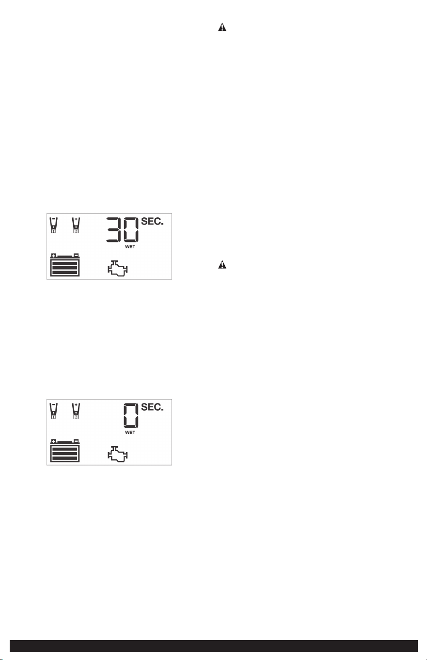
16
El Ícono de Falla parpadeará. El Ícono del Alternador, “ALT” y el Ícono de Estado de
la Batería (vacía) se iluminarán de forma fija.
5. Presione nuevamente el Botón de Verificación del Alternador para detener la
verificación.
6. Al desconectar el cargador de batería, desenchufe el cable de 120 voltios CA y
luego desconecte el cargador de batería de la batería siguiendo el último paso de la
sección “Preparación para Cargar” de este Manual de Instrucciones.
Notas sobre la Función de Verificación del Alternador:
A. IMPORTANTE: Es posible que esta verificación no sea precisa para todas las
marcas, fabricantes y modelos de vehículos. Verifique solo los sistemas de 12 voltios.
B. La unidad puede detectar que el alternador está fuera del rango normal de
voltaje porque se han agregado cargas accesorias al sistema de carga, aumentando
así la demanda de corriente del alternador. ASEGÚRESE DE QUE EL ALTERNADOR
ESTÉ CALIFICADO PARA SOPORTAR LA APLICACIÓN.
Arranque del Motor
1. Consulte la sección “Carga de la Batería” de este Manual de Instrucciones.
Configure el cargador de batería y conéctelo a la batería siguiendo los pasos 1 y 2.
La unidad estará en Modo de Espera.
2. Presione el Botón de Arranque del Motor una vez. Sonará un pitido y la Pantalla
LCD mostrará lo siguiente.
El Ícono del Motor de la Bomba parpadea. La Pantalla Digital muestra un conteo
regresivo para indicar que la unidad está en Modo de Arranque del Motor. Las
barras del Ícono de la Batería cambiarán de vacías a sólidas (de abajo hacia arriba)
repetidamente. Los Íconos de Abrazadera, el Indicador de Tipo de Batería y el Ícono
de Batería se iluminarán de manera fija.
NOTAS:
A. Es posible que la función Arranque del Motor no se inicie si el cargador de
batería detecta que la batería está completamente cargada).
B. La cuenta regresiva de Arranque del Motor se puede finalizar presionando
nuevamente el Botón de Arranque del Motor.
3. Cuando se llegue a “0”, sonará un pitido y la Pantalla LCD mostrará lo siguiente.
El Ícono del Motor de la Bomba se iluminará de forma fija y la Pantalla Digital
mostrará “0 SEC” para indicar que el vehículo está listo para arrancar. El ícono de
Abrazaderas, el Indicador de Tipo de Batería y el Ícono de Batería se iluminan de
manera fija. Las barras del Ícono de la Batería cambiarán de vacías a sólidas (de
abajo hacia arriba) repetidamente.
4. Arranque el motor siguiendo las pautas del fabricante, generalmente en ráfagas
de 3 a 5 segundos. La Pantalla Digital muestra “5 SEC” (una cuenta regresiva de 5
segundos para usar como temporizador al arrancar el motor).
5. Después de arrancar, la unidad ajustará automáticamente la corriente de carga a
aproximadamente 3A durante 5 minutos y luego volverá al Modo de Carga.
IMPORTANTE: La función Arranque del Motor requiere un período de descanso/
enfriamiento entre intentos. Espere de 4 a 5 minutos antes de intentar arrancar el
motor por segunda vez, si es necesario.
6. Al desconectar el cargador de batería, desenchufe el cable de 120 voltios CA y
luego desconecte el cargador de batería de la batería siguiendo el último paso de la
sección “Preparación para Cargar” de este Manual de Instrucciones:
CUIDADO Y MANTENIMIENTO
ADVERTENCIA: Para reducir el riesgo de descarga eléctrica, desenchufe el
cargador de batería del tomacorriente antes de intentar cualquier limpieza. Solo
con pagar los controles no se reducirá este riesgo.
Limpieza y Almacenamiento
Guarde la unidad en un lugar limpio, seco y fresco cuando no esté en uso.
Limpie la carcasa de la unidad y los cables (según sea necesario) con un paño
seco (o ligeramente húmedo). Asegúrese de que la unidad esté completamente
desconectada de la batería y de la fuente de alimentación antes de limpiarla.
Para mantener las condiciones de funcionamiento y maximizar la vida útil de los
cables del cargador, enróllelos siempre que no estén en uso sin apretarlos en el
carrete de almacenamiento incorporado. No los enrolle alrededor de la unidad ni
los doble usando una banda apretada.
SOLUCIÓN DE PROBLEMAS
La unidad no se enciende
• Verifique que el cargador esté conectado correctamente a un tomacorriente activo
de 120 voltios de CA.
La unidad no se carga
• Verifique que el cargador esté conectado correctamente a un tomacorriente activo
de 120 voltios de CA.
• Si la batería a cargar ha caído por debajo de los 2 voltios, no se podrá recargar la
batería con este cargador.
• Asegúrese de que se haya establecido una conexión de cable con la polaridad
adecuada.
ACCESORIOS
ADVERTENCIA: Dado que los accesorios distintos de los ofrecidos por Stanley®
FatMax® no han sido probados con este producto, el uso de dichos accesorios con
esta unidad podría ser peligroso. Para reducir el riesgo de lesiones, use en este
producto solo los accesorios recomendados por Stanley® FatMax®.
Si necesita ayuda con respecto a los accesorios, comuníquese con el fabricante al
1-877-571-2391.
TECHNICAL ASSISTANCE
Para servicio al cliente o asistencia técnica, comuníquese con el fabricante al 1-877-571-
2391.
UN AÑO DE GARANTÍA LIMITADA DEL FABRICANTE
El fabricante, Baccus Global LLC, garantiza este producto contra defectos de materiales
y mano de obra por un período de UN (1) AÑO a partir de la fecha de compra
minorista por parte del comprador usuario final original o desde la fecha de entrega
del bien, lo que sea que ocurra más tarde (“Período de Garantía”).
Si hay un defecto y el fabricante recibe un reclamo válido dentro del Período de
Garantía, el producto defectuoso se puede reemplazar de las siguientes maneras: (1)
Devolviendo el producto al fabricante para su reemplazo. Es posible que el fabricante
solicite un comprobante de compra. (2) Devolviendo el producto al minorista donde se
compró para un cambio (siempre que la tienda sea un minorista participante).
Las devoluciones al minorista deben realizarse únicamente dentro del período de
tiempo de la política de devolución del minorista para cambios. Es posible que se
requiera prueba de compra. Consulte con el minorista su política de devolución
específica con respecto a las devoluciones que superan el tiempo establecido para los
cambios.
La garantía de este fabricante NO se aplica a accesorios, bombillas, fusibles y baterías;
defectos resultantes del desgaste normal, accidentes; daños sufridos durante el envío;
alteraciones; Uso no autorizado; negligencia, mal uso, abuso; y el incumplimiento de
las instrucciones de cuidado y mantenimiento del producto.
Esta garantía del fabricante le otorga a usted, el comprador minorista original,
derechos legales específicos y usted puede tener otros derechos que varían de un
estado a otro o de una provincia a otra. Este producto no está diseñado para uso
comercial. Para registrar su producto con el fabricante, visite www.BaccusGlobal.com.
Las fotografías de este manual pueden diferir de la unidad real.
ESPECIFICACIONES
Entrada: 120V CA, 60Hz, 660W
Salida: 12V CC, 40A, 200A Arranque del Motor (5 segundos ENCENDIDO, 5 minutos APAGADO)
STANLEY® Y EL LOGOTIPO DE STANLEY® SON
MARCAS REGISTRADAS DE STANLEY BLACK
+ DECKER INC. O UNA DE SUS
AFILIADAS, Y SE UTILIZAN BAJO LICENCIA.
Importado por Baccus Global LLC,
621 NW 53rd St., Suite 450, Boca Raton, FL 33487
www.baccusglobal.com 1-877-571-2391
RD111223