
YARDMAX~
Q5
Gas Log Splitter
Operator's Manual
MODEL NUMBER
D YU2566
D YU2866
D YU3066
D YU3566
SERIAL
NUMBER
PURCHASE
DATE
Both model number and serial
number may be found on the
main label.
You
should record
both
of
them in a safe place
for
future
use.
FOR
YOUR
SAFETY
Save
This Manual
for
Future Reference
READ
AND
UNDERSTAND
THE
ENTIRE
MANUAL
BEFORE
OPERATING
MACHINE
Tame
the
Great
Outdoors·
Your
new
YARD MAX® gas log
splitter
offers
quality
construction,
and is easy and safe
to
operate.
With
proper
use
and
care,
it
is
designed
to
give you many years
of
dependable service.
Prepare
to
experience the durability
to
take on any
job-
with
the
ease,
portability, and convenience
of
clean,
gas
splitting!
Discover
the YARDMAX Advantage
At
YARDMAX,
we
understand
that
land
ownership
definitely
has
its
privileges,
but
it
also comes
with
a
great
deal
of
responsibility.
When
duty
calls and you
need
to
respond, will you have what
it
takes
to
tame the
great outdoors?
When looking
for
outdoor power equipment
(OPE)
to
get
the job done right, at the right price, YARD MAX delivers
the perfect combination
of
performance
and
practicality.
YARD MAX
has
a solution that's right
for
you.
MAX
Performance,
MAX
Value,
MAX
Support -
that's YARDMAX
J
Backed
by decades
of
proven manufacturing expertise
J Enhanced design features come standard
J Engineered
for
the best user experience
J Quality metal parts are
used
instead
of
plastic
J A robust warranty supports
all
products
J Budget-friendly prices
make
it
practical
YARDMAX~
Up
for
the
job?
YARD
MAX
is.
TABLE
OF
CONTENTS
Introduction 1
Know
Your
Machine
16
Specifications
3
Operation
18
Symbols
5
Transporting
21
Safety
6 Maintenance 22
Unpacking
the Container 10
Storage
23
Contents
Supplied
11
Troubleshooting
24
Assembly
12
Parts
Diagram
25
1 I
Introduction
YU2566PM02- 1703
Carefully
read
through this entire operator's manual
before using your new unit.
Pay
attention to
all
cautions
and
warnings.
This unit
is
a gasoline engine driven hydraulic log splitter.
It
is
designed
to
split wood
logs
for
use
as
firewood
for
a stove
or
fireplace. This log splitter will only split
logs
lengthwise with the grain.
ENGINE
MANUAL
The Engine Manufacturer
is
responsible
for
all
engine-
related issues
with
regards
to
performance,
power
rating, specifications, warranty
and
service.
Please
refer
to
the Engine Manufacturer's owner/operator's
manual,
packed
separately with your unit, for more information.
EMISSION CONTROL SYSTEM
This equipment
or
its engine may include exhaust
and
evaporative
emission
control
system
components
required
to
meet
U.S.
Environmental Protection Agency
(EPA)
and/or California
Air
Resources Board (CARB)
regulations. Tampering
with
emission
controls
and
components by
unauthorized
personnel may
result
in severe fines
or
penalties. Emission
controls
and
components can
only
be
adjusted by
an
authorized
engine manufacturer's service center.
CALIFORNIA PROPOSITION
65
WARNING
Engine exhaust, some
of
its constituents and certain
product components contain or emit chemicals known to
the state
of
California
to
cause
cancer
and
birth defects
or other reproductive harm. For more information,
go
to
www.P65Warnings.ca.gov.
ENVIRONMENTAL
Recycle
unwanted materials instead
of
disposing of
0
#0/~
them
as
waste.
All
tools,
hoses,
and
packaging
should
W
be
resorted,
taken to
the
local recycling center and
disposed
of
in
an
environmentally
safe
way.
YU2566PM02 · 1703
Gas
Log Splitter » Operator's Manual
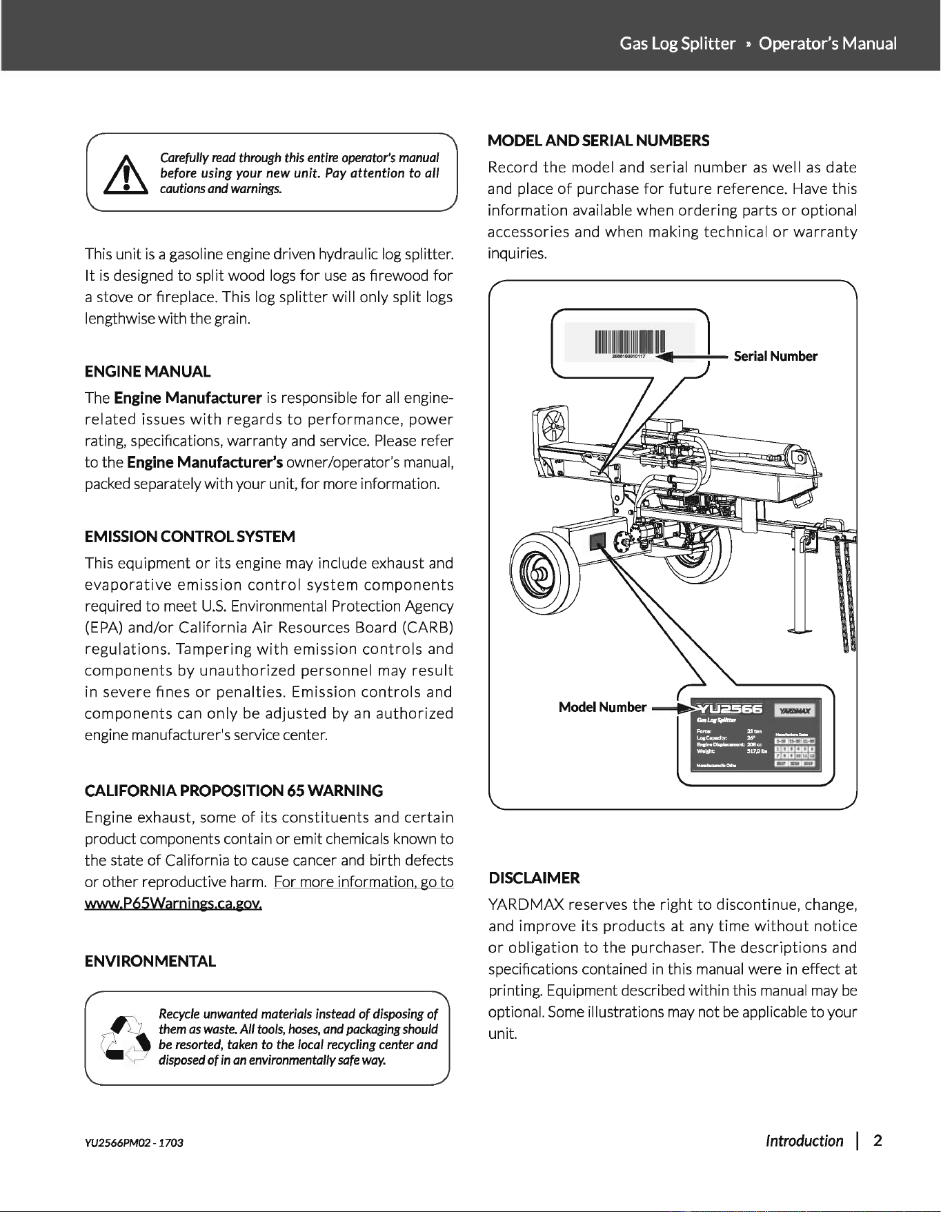
MODEL
AND
SERIAL NUMBERS
Record
the
model and serial number
as
well
as
date
and
place
of
purchase
for
future
reference. Have this
information available when ordering parts
or
optional
accessories and when making technical
or
warranty
inquiries.
uasss
11::!:::!31
......
_
Model Number
~
Fara~
25tan
~~~~ne~cc
~m
w.rstrt:
517.01..
BUD~~~
M-~aw
E:!EIIE!IC!J
DISCLAIMER
YARDMAX reserves the right
to
discontinue, change,
and improve its products
at
any time
without
notice
or
obligation
to
the
purchaser. The descriptions and
specifications contained
in
this manual were
in
effect at
printing. Equipment described within this
manual
may
be
optional.
Some
illustrations
may
not
be
applicable
to
your
unit.
Introduction I 2
SUPPORT
Have
questions about your
YARD
MAX equipment?
Call
us
at 847-327-0566
or
844-YARDMAX, email
us
or
contact
us
via
your
favorite
social
media site.
5
PEC
IF
I
CAT/
ONS
-r--
T
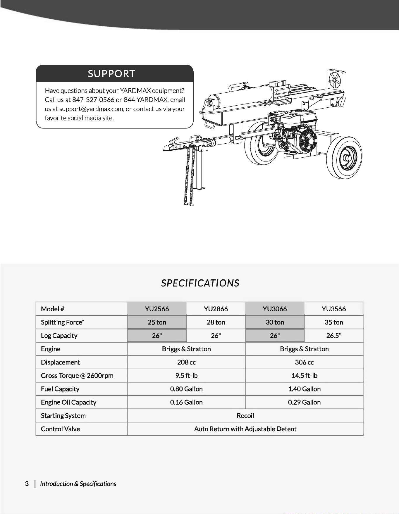
Model#
YU2566 YU2866
Splitting Force*
25ton 28ton
Log
Capacity
26" 26"
Engine Briggs & Stratton
Displacement
208cc
Gross Torque@ 2600rpm 9.5
ft-lb
Fuel
Capacity 0.80Gallon
Engine Oil Capacity
0.16Gallon
Starting System
Recoil
-r--
YU3066 YU3566
30ton
35ton
26" 26.5"
Briggs & Stratton
306cc
14.5ft-lb
1.40Gallon
0.29Gallon
Control Valve
Auto
Return
with
Adjustable Detent
3 I Introduction &
Specifications
-
Gas
Log Splitter » Operator's Manual
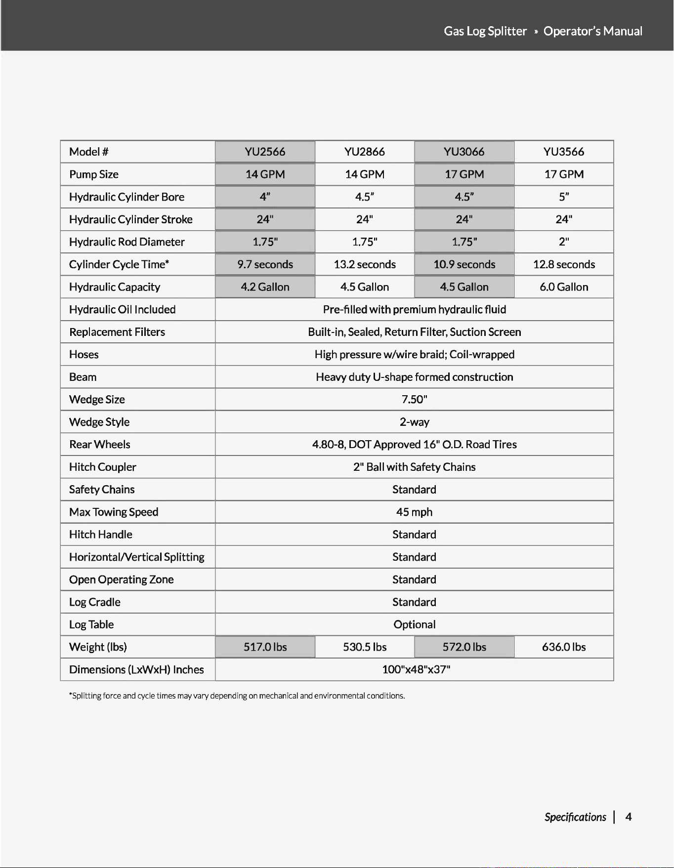
Model#
YU2566 YU2866
I
YU3066 YU3566
Pump
Size
14GPM 14GPM
I
17GPM 17GPM
Hydraulic Cylinder Bore
4"
4.5"
I
4.5" 5"
Hydraulic Cylinder Stroke
24" 24"
I
24" 24"
Hydraulic
Rod
Diameter 1.75" 1.75"
I
1.75" 2"
Cylinder Cycle Time*
9.7seconds 13.2 seconds
I
10.9 seconds 12.8 seconds
Hydraulic Capacity 4.2Gallon 4.5Gallon
I
4.5Gallon 6.0Gallon
Hydraulic Oil Included Pre-filled
with
premium hydraulic fluid
Replacement Filters Built-in, Sealed, Return Filter, Suction Screen
Hoses High pressure
w/wire
braid; Coil-wrapped
Beam
Heavy
duty
U-shape formed construction
Wedge
Size
7.50"
Wedge Style
2-way
Rear Wheels
4.80-8, DOT Approved 16" O.D.
Road
Tires
Hitch Coupler 2" Ball
with
Safety Chains
Safety Chains Standard
Max Towing
Speed
45mph
Hitch Handle Standard
HorizontaiNertical Splitting
Standard
Open Operating Zone
Standard
Log
Cradle Standard
Log
Table Optional
Weight (lbs)
I
517.01bs 530.51bs 572.0 lbs 636.0 lbs
Dimensions (LxWxH) Inches 100"x48"x37"
*Splitting
force
and cycle times may
vary
depending on mechanical and environmental conditions.
Specifications
I 4

SYMBOLS
The
rating
plate
on
your
machine
may
show
symbols.
These
represent
important information about
the
product or instructions
on
its
use.
~
(f)
(j
()
QP
@
®
~
~
&
5 I
Symbols
Read
these instructions carefully.
Wear eye protection.
Wear hearing protection.
Wear protective gloves.
Wear safety footwear.
Do
not
remove
or
tamper
with
the
protection
and
safety devices.
Don't stand
or
sit on the log splitter.
Operate the log splitter
on
level surfaces.
Stay
off
slopes
and
slippery surfaces.
Do
not
touch
parts
that
are
hot
from
operation. Serious burns may result.
No smoking, sparks,
or
flames.
Properly dispose
of
waste oil!
Keep children and bystanders
off
and
away.
Be
sure the engine's switch
is
off
before
transporting the machine
or
performing
any maintenance.
Keep hands and fingers away
from
all
pinch points.
Never remove partially split wood
from
the wedge with your hands. Fingers may
become trapped between the split wood.
Keep
hands
and
feet
away
from
moving parts. Moving parts
can
crush
or
cut.
Keep
hands away from the log stripper.
Always keep body
and
hands away from
pin holes
or
nozzles
that
eject hydraulic
fluid under pressure. Escaping hydraulic
fluid
can
puncture skin
and
cause blood
poisoning.
Thrown objects.
Check
and
fill hydraulic oil.
Follow the direction indicated
to
use
the
control lever.
For logs
that
are
not
cut
square,
the
longest
portion
of
the
log should be
rotated down
and
the most square end
placed toward the
end
plate.
Do not transport with objects
on
the machine.
8
MAX
4r-·
~~~
I
,,_.,
:J
l
<3
I @ @
Maximum towing
speed
of
45
mph.
YU2566PM02- 1703
Gas
Log Splitter » Operator's Manual
SAFETY
GENERAL
SAFETY
RULES
UNDERSTAND
YOUR
MACHINE
Read
this manual
and
labels affixed
to
the machine
to
understand
its limitations
and
potential hazards.
Be
thoroughly
familiar
with
the
controls
and
their
proper
operation. Know
how
to
stop
the
machine and disengage
the
controls quickly.
Make sure
to
read
and
understand all the instructions
and
safety
precautions
as
outlined in
the
Engine
Manufacturer's
manual
packed
separately
with
your unit. Do not attempt
to
operate the
machine until you fully understand how
to
properly operate
and
maintain the engine
and
how
to
avoid accidental injuries and/or
property damage.
If
the unit
is
to
be
used
by someone other than original purchaser
or
loaned, rented,
or
sold, always provide this manual
and
any
needed safety training before operation. The user
can
prevent
and
is
responsible
for
accidents
or
injuries
that
may occur
to
themselves, other people,
and
property.
Do
not
force
the
machine. Use
the
correct
machine
for
your
application. The correct machine will do the
job
more efficiently
and
safer at the rate
it
was designed.
PERSONAL
SAFETY
Do not permit children
to
operate this machine at any time.
Keep children, pets,
and
other
people
not
using
the
unit
away
from the
work
area.
Be
alert
and
shut
off
unit
if
anyone enters
work
area.
Keep
children under the watchful care
of
a responsible
adult.
Do not operate the machine while under the influence
of
drugs,
alcohol,
or
any medication that could affect your ability
to
use
it
properly.
Dress properly. Wear heavy long pants, boots,
and
gloves. Do not
wear loose clothing, short pants,
or
jewelry
of
any kind. Secure
long hair
so
it
is
above shoulder level. Keep your hair, clothing,
and
gloves away
from
moving parts. Loose clothes, jewelry,
or
long hair
can
be
caught in moving parts.
Protect eyes, face,
and
head from objects
that
may
be
thrown
from the unit. Always wear safety goggles
or
safety
glasses
with
side shields when operating.
YU2566PM02- 1703
Wear appropriate hearing protection.
Always keep hands
and
feet
away from all moving parts during
operation. Moving parts
can
cut
or
crush body parts.
Always
keep
hands
and
feet away from all pinch points.
Do not touch parts that might
be
hot from operation. Allow parts
to
cool before attempting
to
maintain, adjust,
or
service.
Stay alert, watch
what
you are doing, and use common sense
when operating the machine.
Do
not
overreach. Do
not
operate
the
machine while barefoot
or
when wearing sandals
or
similar lightweight footwear. Wear
protective
footwear
that
will
protect
your
feet
and improve
your
footing
on
slippery
surfaces. Keep
proper
footing
and
balance at all times. This enables better control
of
the machine in
unexpected situations.
INSPECT
YOUR
MACHINE
Check your machine before starting it.
Keep
guards in place
and
in
working
order. Make sure all nuts, bolts, etc., are securely
tightened.
Never operate the machine when
it
is
in need
of
repair
or
is
in
poor mechanical condition. Replace damaged, missing,
or
failed
parts before using it. Check
for
fuel leaks. Keep
the
machine in
safe working condition.
Do not
use
the machine
if
the engine's switch does
not
turn
it
on
or
off.
Any
gasoline powered machine
that
can't
be
controlled
with
the engine switch
is
dangerous
and
must
be
replaced.
Regularly check
to
see
that
keys and adjusting wrenches are
removed from the machine area before starting it. A wrench
or
a key
that
is
left
attached
to
a rotating part
of
the machine may
result in personal injury.
Avoid accidental starting.
Be
sure the engine's switch
is
off
before
transporting
the
machine
or
performing
any maintenance
or
service on the unit. Transporting
or
performing maintenance
or
service on a machine
with
its switch
on
invites accidents.
If
the
machine should
start
to
vibrate
abnormally,
stop
the
engine (motor)
and
check immediately
for
the
cause.
Vibration
is
generally a warning sign
of
trouble.
Safety I 6
ENGINE
SAFETY
This machine
is
equipped
with
an internal combustion engine.
Do
not
use
on
or
near any unimproved, forest covered,
or
brush
covered land unless the exhaust system
is
equipped
with
a spark
arrester meeting applicable local, state,
or
federal laws.
In
the
state
of
California, a spark
arrester
is
required
by
law.
Other
states have similar laws. A spark arrester,
if
used, must
be
maintained in effective working
order
by the operator.
Never
start
or
run
the
engine inside a closed area. The exhaust
fumes are dangerous, containing carbon monoxide, an odorless
and
deadly
gas.
Operate
this
unit
only
in
a
well-ventilated
outdoor area.
Do
not
tamper
with
the engine
to
run
it
at
excessive speeds. The
maximum engine speed
is
preset
by
the
manufacturer
and is
within
safety limits.
See
engine manual.
Keep a Class B fire extinguisher on hand when operating this log
splitter
in
dry
areas
as
a precautionary measure.
FUEL
SAFETY
Fuel
is
highly flammable, and
its
vapors can explode
if
ignited.
Take precautions when using
to
reduce
the
chance
of
serious
personal injury.
When
refilling
or
draining
the
fuel tank, use an approved fuel
storage container while in a clean, well-ventilated
outdoor
area.
Do
not
smoke,
or
allow sparks, open flames,
or
other
sources
of
ignition
near
the
area
while
adding fuel
or
operating
the
unit.
Never fill
the
fuel tank indoors.
Keep grounded
conductive
objects, such
as
tools, away
from
exposed, live electrical parts and connections
to
avoid sparking
or
arcing. These events could ignite fumes
or
vapors.
Always stop
the
engine and allow
it
to
cool before filling the fuel
tank. Never remove the
cap
of
the fuel tank
or
add fuel while the
engine
is
running
or
when
the
engine
is
hot. Do
not
operate the
machine
with
known leaks in the fuel system.
Loosen the fuel tank
cap
slowly
to
relieve any pressure in the tank.
Never overfill
the
fuel tank. Fill
the
tank
to
no more than
1/2"
below the bottom
of
the filler neck
to
provide space
for
expansion
as
the
heat
of
the
engine
can
cause fuel
to
expand.
Replace
all fuel tank
and
container
caps
securely
and
wipe up spilled
fuel. Never operate the unit
without
the fuel
cap
securely in
place.
7 I Safety
Avoid creating a source
of
ignition
for
spilled fuel.
If
fuel
is
spilled,
do
not
attempt
to
start
the
engine
but
move
the
machine away
from the area
of
spillage and avoid creating any source
of
ignition
until fuel vapors have dissipated.
When fuel
is
spilled on yourself
or
your
clothes, wash
your
skin
and change clothes immediately.
Store fuel in containers specifically designed and approved
for
this purpose.
Store fuel in a cool, well-ventilated area, safely away
from
sparks,
open flames,
or
other
sources
of
ignition.
Never
store
fuel
or
a machine
with
fuel
in
the
tank
inside a
building where fumes may reach a spark, open flame,
or
any
other
source
of
ignition, such
as
a
water
heater, furnace,
or
clothes
dryer.
Allow
the engine
to
cool before storing in any enclosure.
HYDRAULIC
SYSTEM
SAFETY
The hydraulic system
of
the machine requires careful inspection
along
with
the mechanical parts.
Be
sure
to
replace frayed, kinked,
cracked,
or
otherwise
damaged
hydraulic
hoses
or
hydraulic
components.
Hydraulic fluid can result in severe burns. Fluid in the hydraulic
system
can
penetrate skin and result in serious
injury
or
death.
Be
sure
to
stop the engine and relieve hydraulic pressure before
doing any
work
on hydraulic parts.
Keep body and hands away
from
pin holes
or
nozzles
that
expel
hydraulic fluid when under pressure.
Use
paper
or
cardboard,
not
hands,
to
search
for
leaks.
Ensure all hydraulic fluid connections are
tight
and all hydraulic
hoses and lines are in good condition before applying pressure
to
the
system.
Do
not
remove
the
cap
from
the
hydraulic tank
or
reservoir while
the
machine is running. The
tank
could
contain
hot
oil
under
pressure, which could result in serious injury.
Do
not
adjust
the
pressure
setting
on
the
hydraulic
pump
or
valve.
If
injured by escaping fluid, no
matter
how
small the wound
is,
see
a doctor
at
once. A typical injection injury may
be
a small wound
that
does
not
look serious. However, severe infection
or
reaction
can
result
if
proper
medical
treatment
is
not
administered
immediately by a doctor
who
is
familiar
with
injection injuries.
YU2566PM02 · 1703
Gas
Log Splitter » Operator's Manual
SPECIFIC
SAFETY
RULES
PREPARATION
OF
THE
LOG
Both
ends
of
the
log should be
cut
as
square
as
possible
to
prevent the log from rotating
out
of
the splitter during operation.
Never split logs greater than the specified log capacity.
Do
not
operate
the
log
splitter
on icy, wet, muddy,
or
slippery
ground. Only operate your log splitter on level ground.
Operating
on
a
slope
could
cause
the
log
splitter
to
roll
over
or
logs
to
fall off
the
equipment,
which
could
result
in
injury.
Do not move the log splitter over hilly
or
uneven terrain
without
a
tow
vehicle
or
adequate help.
Keep
the
work
area
free
of
clutter.
Remove
split
wood
from
around
the
log
splitter
immediately
after
each use
to
avoid
potential tripping.
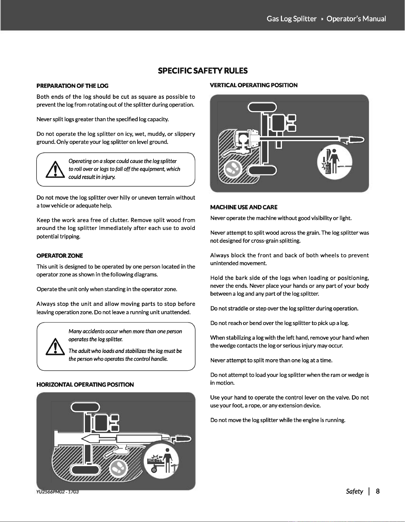
OPERATOR
ZONE
This unit
is
designed
to
be
operated by one person located in the
operator zone
as
shown in the following diagrams.
Operate the
unit
only when standing in the operator zone.
Always
stop
the
unit
and
allow
moving
parts
to
stop
before
leaving operation zone. Do not leave a running
unit
unattended.
Many
accidents
occur
when
more
than
one
person
operates
the
log
splitter.
The
adult
who
loads
and
stabilizes
the
log
must
be
the
person
who
operates
the
control
handle.
HORIZONTAL
OPERATING
POSITION
VERTICAL
OPERATING
POSITION
MACHINE
USE
AND
CARE
Never operate the machine
without
good visibility
or
light.
Never attempt
to
split wood across the grain. The log splitter was
not designed
for
cross-grain splitting.
Always
block
the
front
and back
of
both
wheels
to
prevent
unintended movement.
Hold
the
bark
side
of
the
logs
when
loading
or
positioning,
never the ends. Never place your hands
or
any part
of
your body
between a log
and
any part
of
the log splitter.
Do not straddle
or
step over the log splitter during operation.
Do not reach
or
bend over the log splitter
to
pick up a log.
When stabilizing a log
with
the
left
hand, remove your hand when
the wedge contacts the log
or
serious injury may occur.
Never attempt
to
split more than one log
at
a time.
Do
not
attempt
to
load your log splitter when the ram
or
wedge
is
in motion.
Use
your hand
to
operate the control lever on the valve. Do not
use
your foot, a rope,
or
any extension device.
Do not move the log splitter while the engine
is
running.
Safety I 8
TOWING
SAFETY
Check all local and state regulations regarding towing, licensing,
and lights before
towing
your log splitter.
Before towing the log splitter, check tires
for
excessive wear, cuts,
or
damage. Check
for
proper
tire
inflation. Add
air
as
required.
Do
not
over inflate tires. Serious injury
can
result
if
tires explode.
Check before towing
to
make sure the log splitter
is
correctly and
securely attached
to
the
towing
vehicle and
the
safety chains are
secured
to
the
hitch
or
bumper
of
the vehicle
with
enough slack
to
allow turning. Always
use
a class
I,
2" ball
with
this log splitter.
Make
sure
the coupler
is
tight before towing
and
after towing 50
miles.
Never transport cargo on
the
log splitter.
9 I Safety
Never allow anyone
to
ride
or
sit
on the log splitter.
Always stop the engine, lock the beam in the horizontal position,
and close the fuel shut-off valve when transporting the unit.
Use extra care when
towing
the
log splitter. Do
not
exceed 45
mph. Towing
the
log splitter at a speed
greaterthan45
mph could
result in loss
of
control, damage
to
the equipment, serious injury,
or
death.
Avoid sharp turns and steep angles. Avoid large holes
or
ditches
when
towing
the
equipment. Always be careful when backing
up
with
your
log
splitter
when
towing;
it
could jackknife. Use
caution when backing up; a
spotter
outside the vehicle
is
highly
recommended.
Disconnect
the
log
splitter
from
the
towing
vehicle before operating it.
YU2566PM02- 1703
Gas
Log
Splitter • Operator's Manual
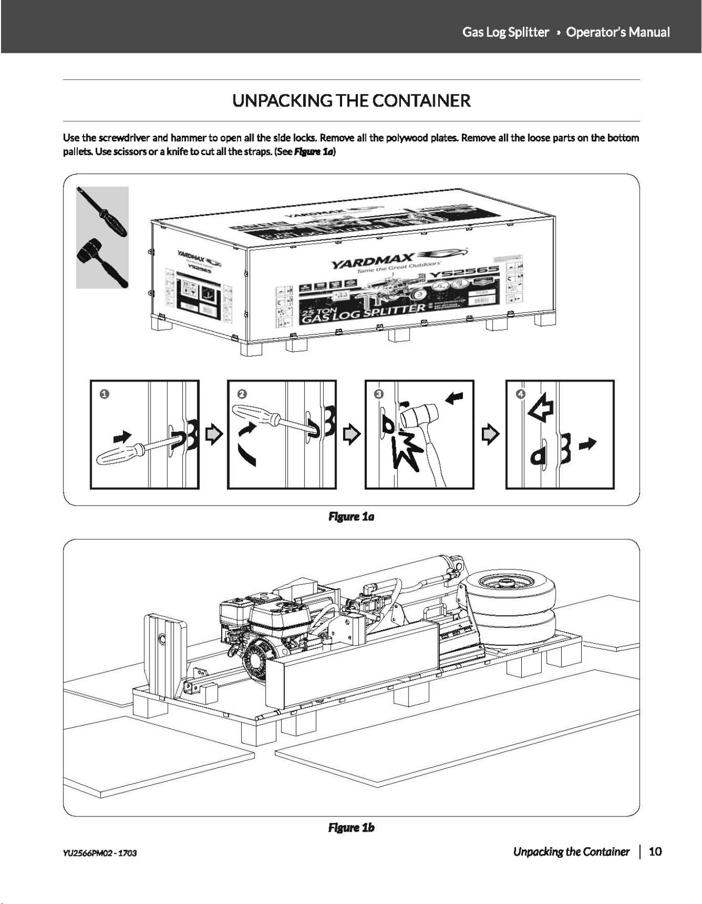
UNPACKING THE CONTAINER
Use
the screwdriver
and
hammer
to
open
all the
side
locks.
Remove
all
the
polywood
plates.
Remove
all the
loose
parts
on
the bottom
pallets.
Use
scissors
or
a knife
to
cut all the
straps.
(See
Ram fd)
flprB1a
flaure:1&
Vli2566PM02
-1703
Unpacking
the Container I
10
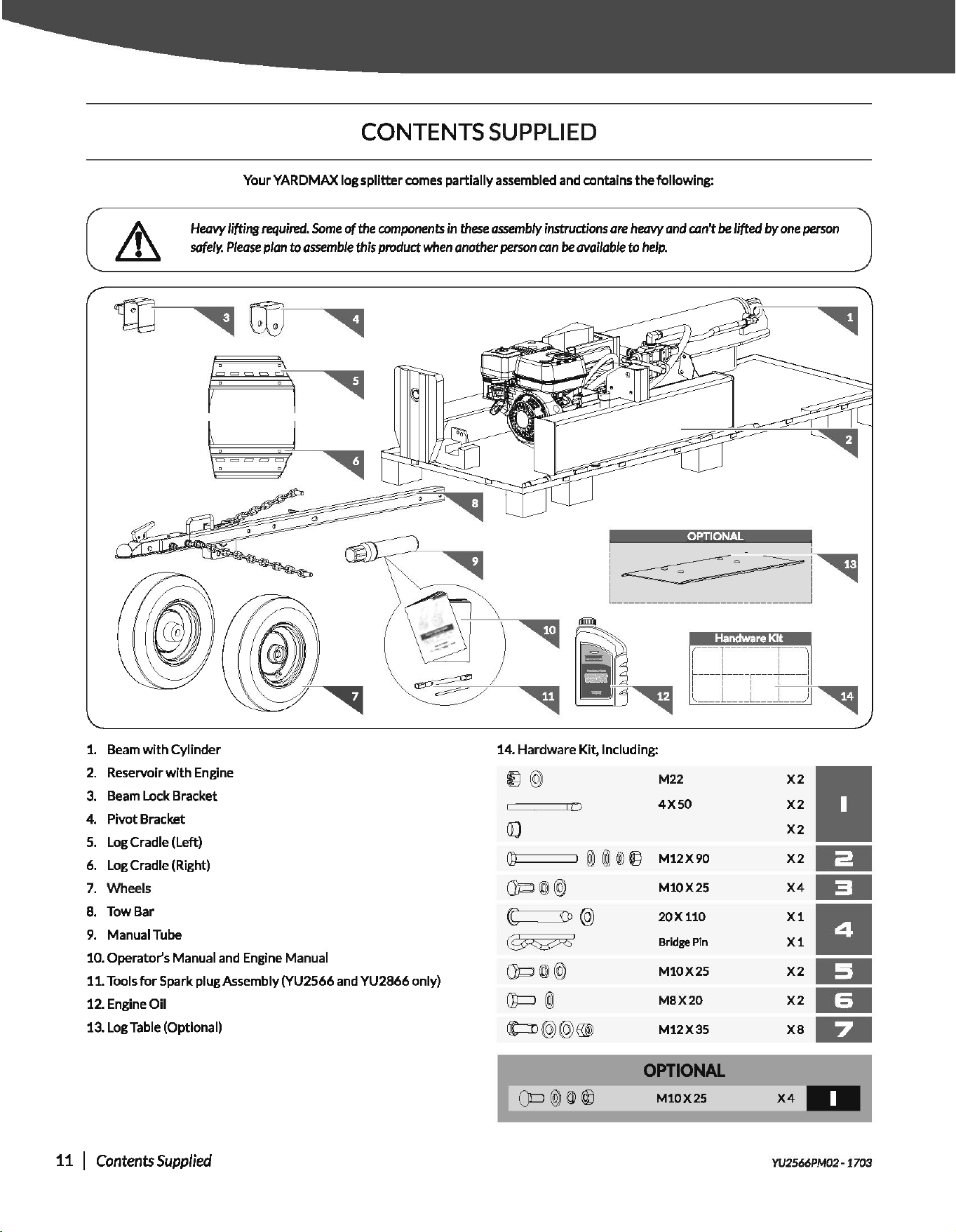
CONTENTS SUPPLIED
Your
YARDMAX
log
splitter
comes
partially
assembled and contains
the
following:
Heavy
lifting
required.
Some
of
the
components
in
these
assembly
instructions
are
heavy
and
mn't be lifted
by
one
person
safely.
Please
plan
to
assemble
this
product
when
another
person
can
be
available
to
help.
1. Beam
with
Cylinder
2. Reservoir
with
Engine
3.
Beam Lock Bracket
4. Pivot Bracket
5.
Log Cradle (Left)
6. Log
Cradle (Right)
7.
Wheels
8.
Tow
Bar
9. Manual Tube
10.
Operator's
Manual and Engine Manual
11.
Tools
for
Spark plug Assembly (YU2566 and
YU2866
only)
12.
Engine
Oil
13.
Log Table (Optional)
11 I Contents Supplied
I
I
I
I
I
OPTIONAL
I I
l
----------------------------------~
Handware
Kit
14.
Hardware
Kit, Including:
M22
4XSO
Q;Ci
==::::::J
@ @ ®
Q""j
M12 X
90
Q]d
©J
@
([
OJ@
~
·
Q'P
©J
@
Q'p
@J
tt=o@@
®J
M10X
25
20X110
Bridge Pin
M10X
25
M8X20
M12
X35
OPTIONAL
M10X25
X2
X2
X2
X2
X4
X1
X1
X2
X2
YU2
5
66PM02
-1703
Gas
Log Splitter » Operator's Manual
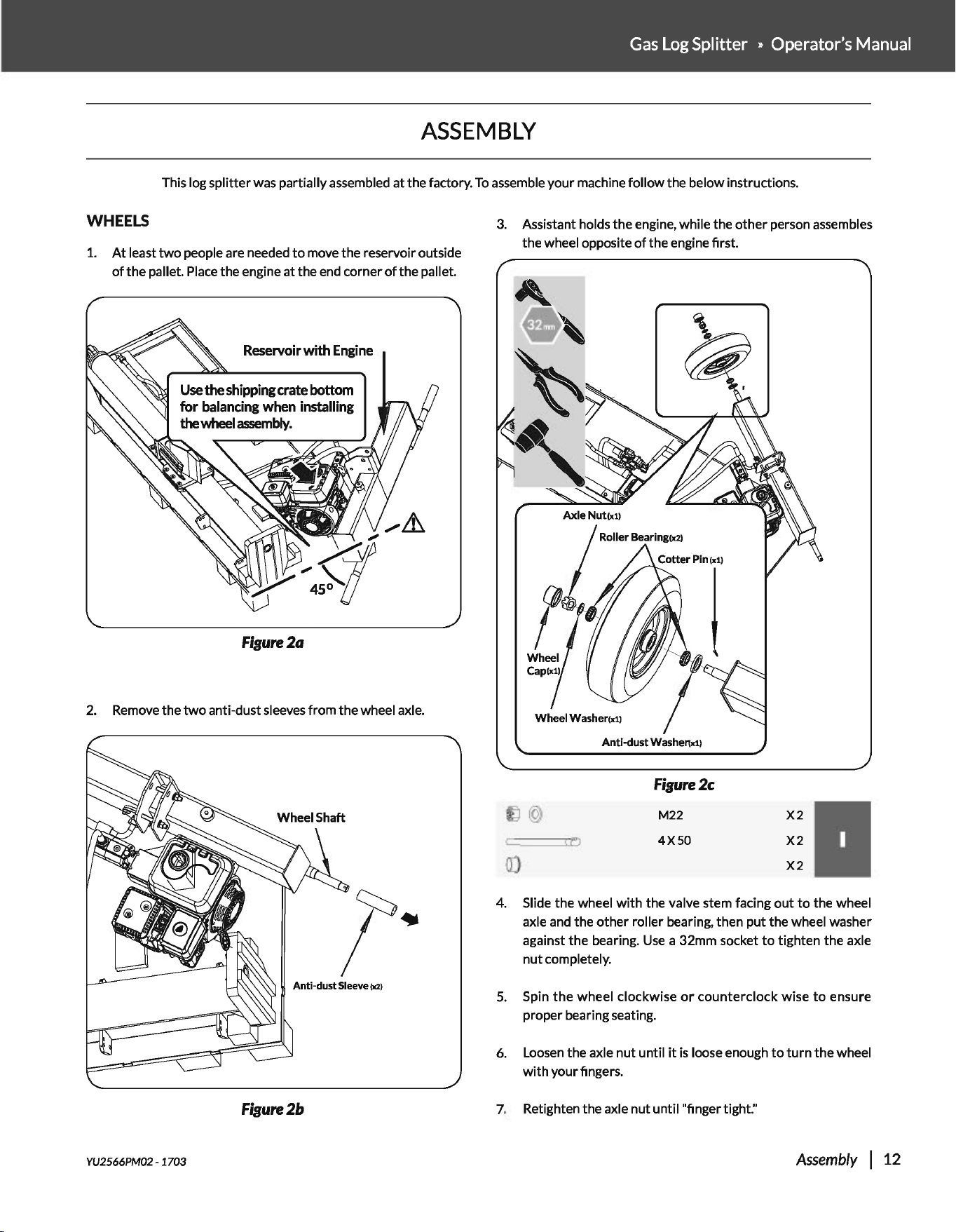
ASSEMBLY
This log splitter was partially assembled at the factory.
To
assemble your machine follow the below instructions.
WHEELS
1.
At
least
two
people are needed
to
move the reservoir outside
of
the pallet.
Place
the engine at the end corner
of
the pallet.
Reservoir
with
Engine
Figure2a
2.
Remove the
two
anti-dust sleeves from the wheel axle.
Anti-dust Sleeve (x2)
Figure2b
YU2566PM02- 1703
3.
Assistant holds the engine, while the other person assembles
the wheel opposite
of
the engine first.
Cotter
Pin(x1)
I
Anti-dust
Washertx1l
Figure2c
M22
4XSO
X2
X2
X2
4. Slide the wheel
with
the valve stem facing
out
to
the wheel
axle
and
the
other
roller bearing, then put the wheel washer
against the bearing.
Use
a 32mm socket
to
tighten the axle
nut completely.
5.
Spin
the
wheel clockwise
or
counterclockwise
to
ensure
proper bearing seating.
6.
Loosen
the axle
nut
until
it
is
loose enough
to
turn
the wheel
with
your fingers.
7.
Retighten the axle
nut
until "finger tight:•
Assembly
I 12
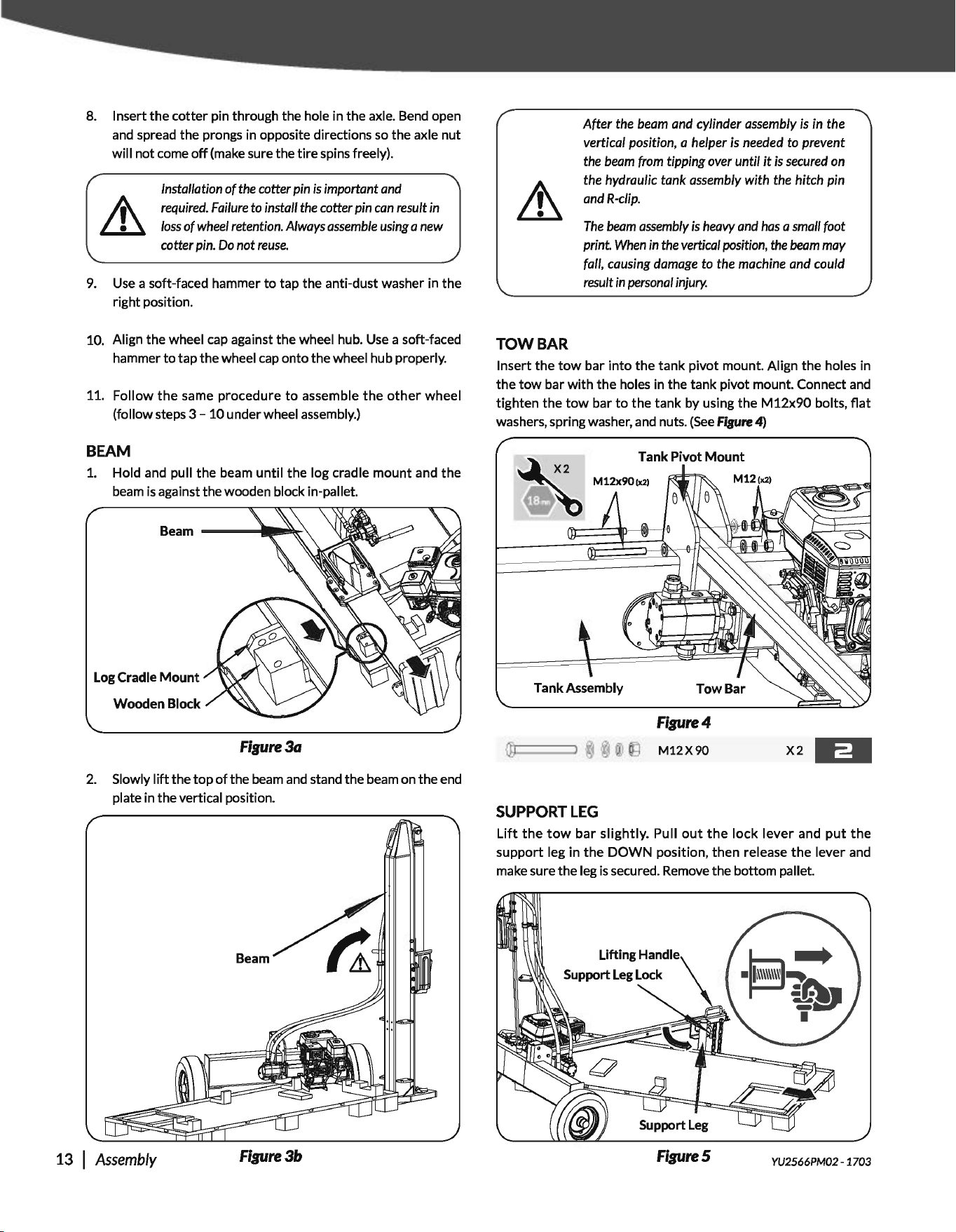
8.
Insert the cotter pin through the hole in the axle.
Bend
open
and
spread the prongs in opposite directions
so
the axle nut
will not come
off
(make
sure the
tire
spins freely).
Installation
of
the
cotter
pin
is
important
and
required.
Failure
to
install
the
cotter
pin
can
result
in
loss
of
wheel
retention. Always
assemble
using
a
new
cotter
pin.
Do
not
reuse.
9.
Use
a soft-faced hammer
to
tap the anti-dust washer in the
right position.
10. Align the wheel
cap
against the wheel hub.
Use
a soft-faced
hammer
to
tap the wheel
cap
onto the wheel hub properly.
11. Follow
the
same procedure
to
assemble
the
other
wheel
(follow steps
3-
10 under wheel
assembly.)
BEAM
1.
Hold
and
pull the beam until
the
log cradle mount and
the
beam
is
against the wooden block in-pallet.
Log
Cradle
Mount
Wooden
Block
Figure3a
2.
Slowly
lift
the top
of
the
beam
and
stand the
beam
on the
end
plate in the vertical position.
13 I
Assembly
Figure3b
TOW
BAR
After the
beam
and cylinder
assembly
is
in
the
vertical position, a helper
is
needed
to
prevent
the
beam
from
tipping
over
until
it
is
secured
on
the hydraulic tank
assembly
with the hitch pin
and
R-clip.
The
beam
assembly
is
heavy
and
has
a
small
foot
print.
When
in
the
vertical
position,
the
beam
may
fall, causing
damage
to
the machine
and
could
result
in
personal
injury.
Insert the
tow
bar into the tank pivot mount. Align the holes in
the
tow
bar with the holes in the tank pivot mount. Connect
and
tighten the
tow
bar
to
the tank by using the
M12x90
bolts,
flat
washers, spring washer,
and
nuts.
(See
fisure 4)
Tank
Pivot Mount
2
M12x90(x2)
.
Figure4
@
@)
iJ)
[')
M12X90
X2
-----
SUPPORT
LEG
Lift
the
tow
bar
slightly. Pull
out
the
lock lever and
put
the
support leg in
the
DOWN
position, then release
the
lever and
make
sure the leg
is
secured.
Remove
the bottom pallet.
FigureS
YU2566PM02 · 1703
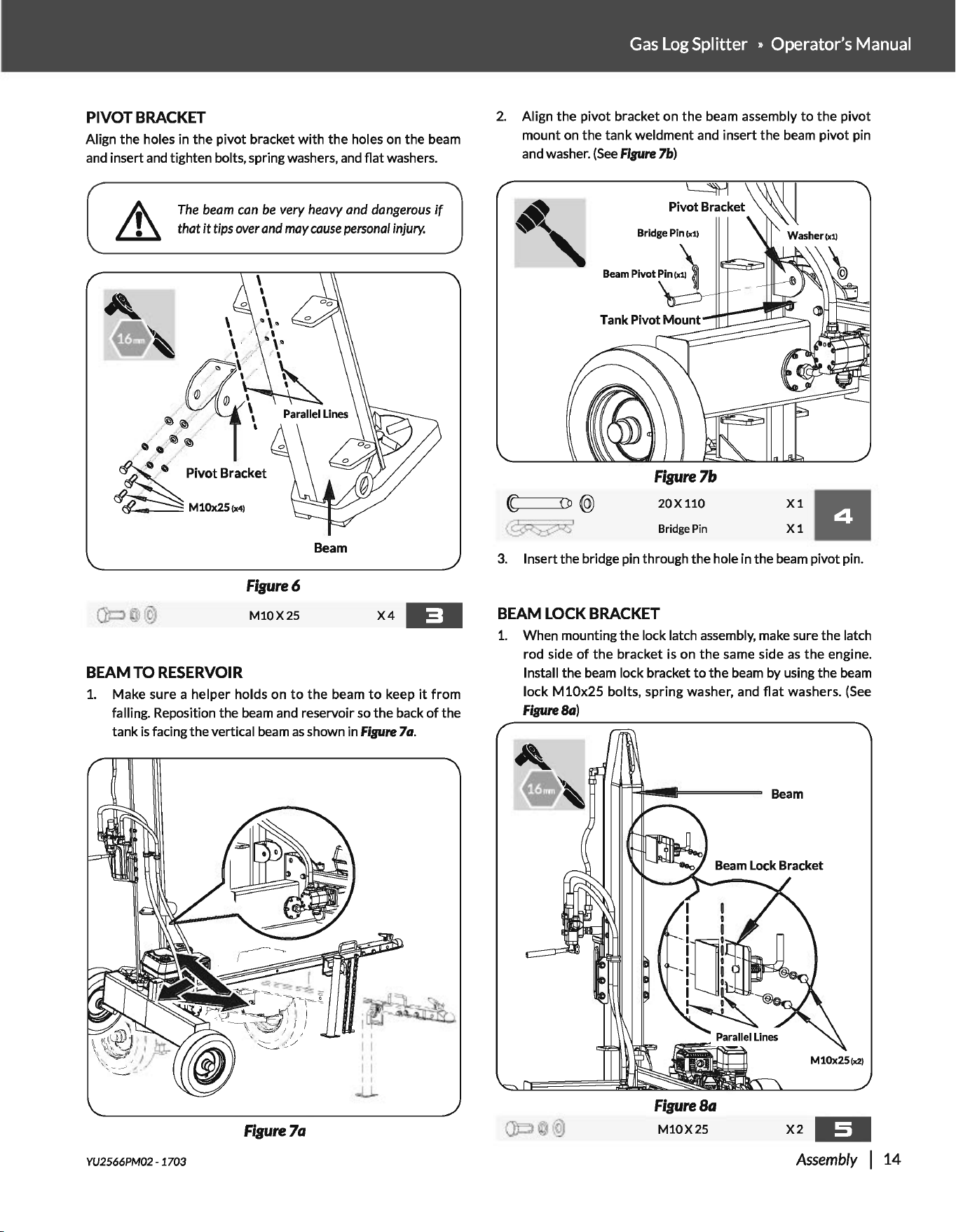
PIVOT
BRACKET
Align the holes in the pivot bracket
with
the holes on the beam
and
insert
and
tighten bolts, spring washers,
and
flat washers.
The
beam
can
be
very heavy and
dangerous
if
that
it
tips
over
and
may
cause
personal
injury.
Beam
Figure6
M10X25
X4
-=·
BEAM
TO
RESERVOIR
1.
Make sure a helper holds on
to
the
beam
to
keep
it
from
falling. Reposition the
beam
and
reservoir
so
the back
of
the
tank
is
facing the vertical
beam
as
shown in
Fipre
7a.
Figure7a
YU2566PM02 · 1703
Gas
Log Splitter » Operator's Manual
2.
Align the pivot bracket on
the
beam assembly
to
the
pivot
mount on the tank weldment
and
insert the
beam
pivot pin
and
washer.
(See
Flpre
7b)
[
n@
@Gii)'
~
Pivot Bracket
Figure7b
20X110
Bridge
Pin
X1
11
X1
3.
Insert the bridge pin through the hole in the
beam
pivot pin.
BEAM
LOCK
BRACKET
1.
When mounting the lock latch
assembly,
make
sure the latch
rod side
of
the
bracket
is
on
the
same side
as
the
engine.
Install the
beam
lock bracket
to
the
beam
by using the
beam
lock
M10x25
bolts, spring washer, and
flat
washers.
(See
FipreSa)
Figure
Sa
M10X25
X2
~-
Assembly
I
14
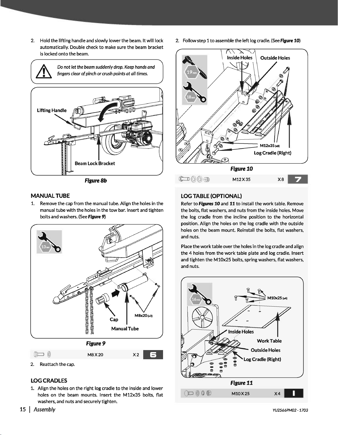
2.
Hold the lifting handle and slowly lower
the
beam.
It
will lock
automatically. Double check
to
make sure the beam bracket
is
locked
onto
the beam.
~
Do
not let
the
beam
suddenly
drop.
Keep
hands
and
~
fingers
clear
of
pinch or
crush
points
at
all
times.
Beam
Lock
Bracket
FigureSb
MANUAL
TUBE
1.
Remove the
cap
from
the
manual tube. Align
the
holes in the
manual tube
with
the holes in
the
tow
bar.
Insert and tighten
bolts and washers.
(See
Fipre
9)
Cap
Manual
Tube
Figure9
M8X20
X2
·=-
2.
Reattach the
cap.
LOG
CRADLES
1.
Align the holes on the right log cradle
to
the
inside and lower
holes on the beam mounts. Insert
the
M12x35 bolts,
flat
washers, and nuts and securely tighten.
15 I
Assembly
2.
Follow step 1
to
assemble the left log crad I
e.
(See
Fisure 10)
Figure10
M12X35
xs
LOG
TABLE
(OPTIONAL)
Refer
to
Fipres
10
and 11
to
install the
work
table. Remove
the bolts,
flat
washers, and nuts
from
the inside holes. Move
the log cradle from
the
incline position
to
the horizontal
position. Align the holes
on
the log cradle
with
the
outside
holes on the beam mount. Reinstall
the
bolts,
flat
washers,
and nuts.
Place the
work
table over the holes in the log cradle and align
the 4 holes from
the
work
table plate and log cradle. Insert
and tighten the M 10x25 bolts, spring washers,
flat
washers,
and nuts.
~
M10x25tx4l
WorkTable
Log
Cradle
(Right)
Figure11
M10X25
X4-
YU2566PM02- 1703
Gas
Log Splitter » Operator's Manual
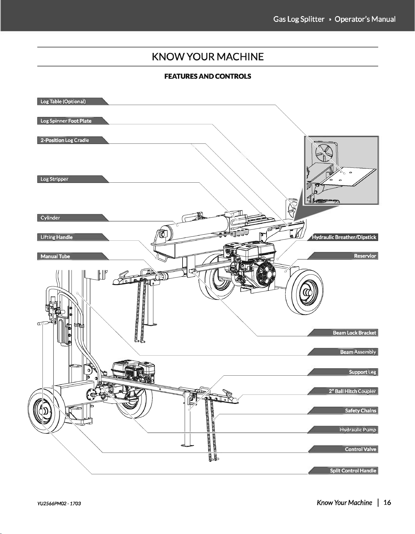
KNOW
YOUR MACHINE
FEATURES
AND
CONTROLS
Log Table (Optional)
Log Spinner Foot Plate
2-Position Log Cradle
Log
Stripper
Beam Lock Bracket
Beam Assembly
Support Leg
®ffl§3M
Hydraulic Pump
Control
Valve
Split
Control
Handle
YU2566PM02- 1703
Know
Your
Machine
I
16
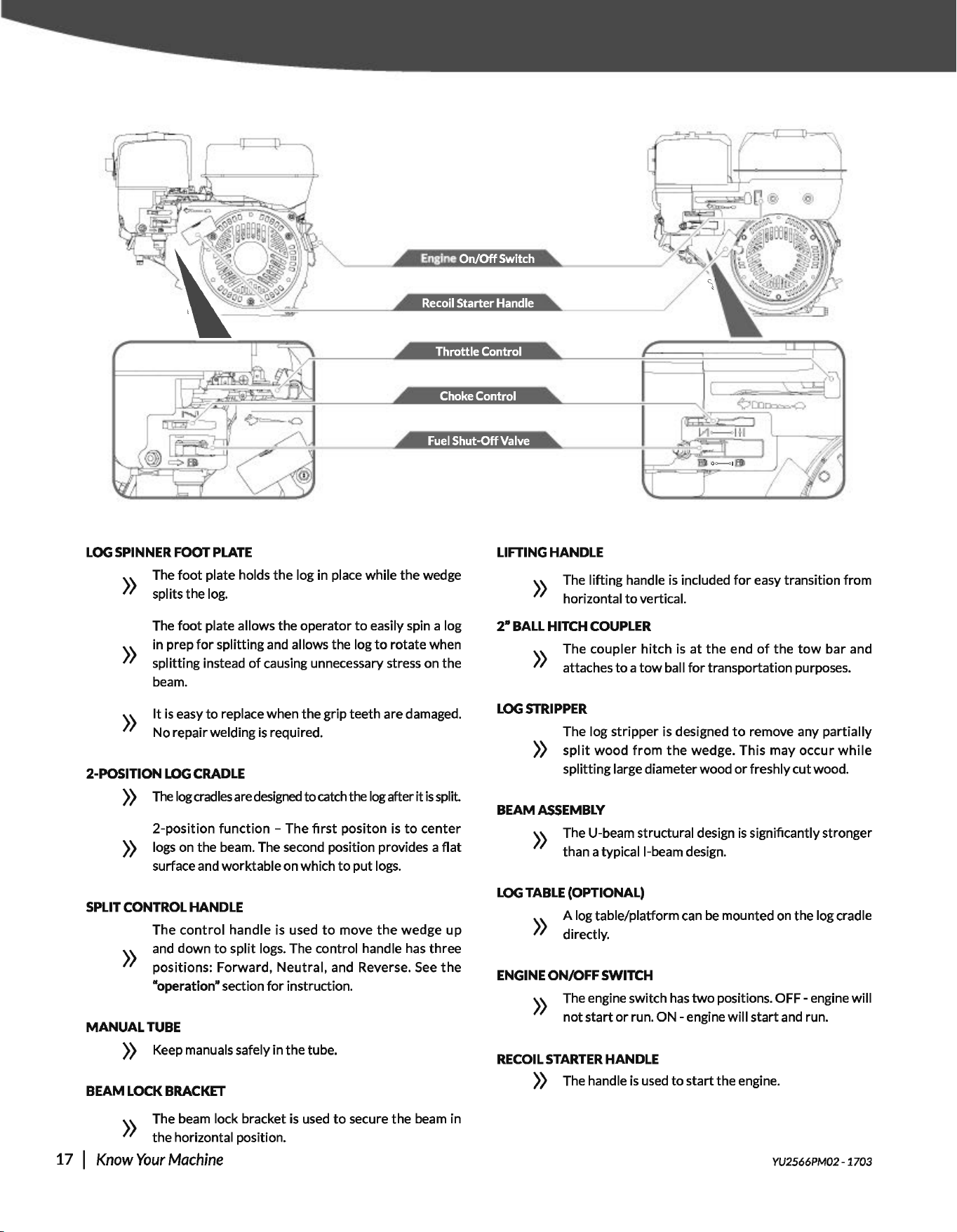
Recoil
Starter
Handle
LOG
SPINNER
FOOT
PLATE
\.\. The
foot
plate holds
the
log in place while
the
wedge
//
splits the log.
The
foot
plate allows the operator
to
easily spin a log
in prep
for
splitting and allows the log
to
rotate when
))
splitting instead
of
causing unnecessary stress on
the
beam.
))
It
is
easy
to
replace when the grip teeth are damaged.
No repair welding
is
required.
2-POSITION
LOG
CRADLE
))
The
log
cradles
are
designed
to
catch the log after
it
is
split
2-position
function
-The
first
positon
is
to
center
))
logs on the beam. The second position provides a
flat
surface and worktable on which
to
put
logs.
SPLIT
CONTROL
HANDLE
The
control
handle is used
to
move
the
wedge up
and down
to
split
logs. The control handle
has
three
))
positions: Forward,
Neutral,
and Reverse.
See
the
"operation" section
for
instruction.
MANUAL
TUBE
))
Keep manuals safely in
the
tube.
BEAM
LOCK
BRACKET
))
The beam lock bracket
is
used
to
secure
the
beam in
the
horizontal position.
17
I
Know
Your
Machine
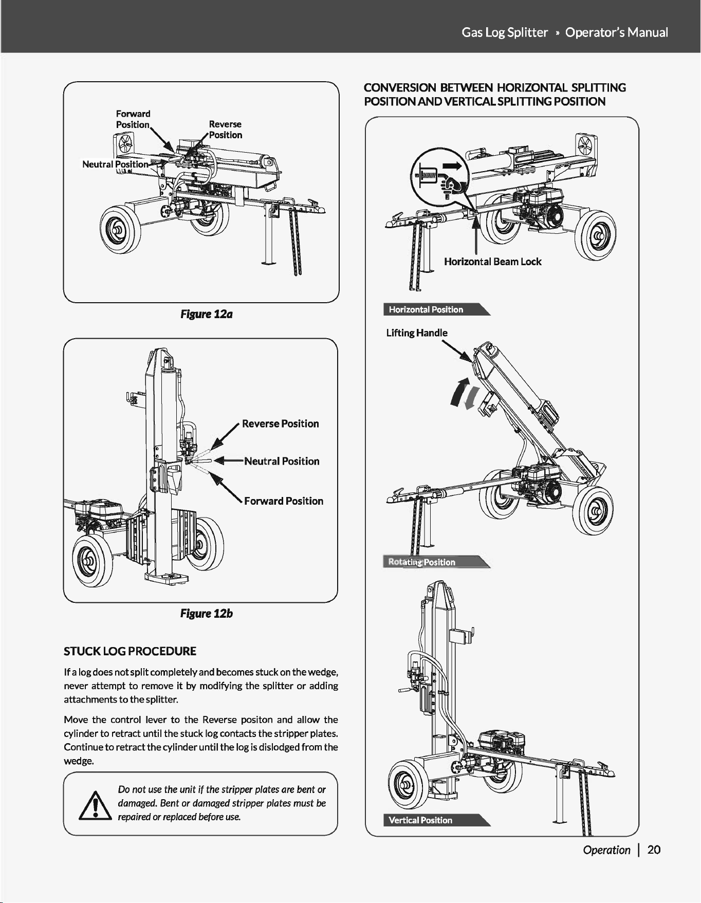
LIFTING
HANDLE
))
The lifting handle
is
included
for
easy transition from
horizontal
to
vertical.
2•
BALL
HITCH
COUPLER
The
coupler
hitch
is
at
the
end
of
the
tow
bar
and
))
attaches
to
a
tow
ball
for
transportation purposes.
LOG
STRIPPER
The log
stripper
is
designed
to
remove any partially
))
split
wood
from
the
wedge. This may
occur
while
splitting large diameter wood
or
freshly cut wood.
BEAM
ASSEMBLY
))
The U-beam structural design
is
significantly stronger
than a typicall-beam design.
LOG
TABLE
(OPTIONAL)
\.\. A log table/platform
can
be
mounted on the log cradle
//
directly.
ENGINE
ON/OFF SWITCH
))
The engine switch
has
two
positions.
OFF-
engine will
not
start
or
run.
ON
-engine
will
start
and run.
RECOIL
STARTER
HANDLE
))
The handle
is
used
to
start
the engine.
YU2566PM02- 1703
FUEL SHUT-OFF VALVE
The fuel
shut
-
off
has
two
position. CLOSED
(It))
))
- use
this
position
to
service,
transport,
or
store
the
unit.
))
OPEN
(Hi\)-
use this position
to
run
the
unit.
CHOKE CONTROL
»
The choke control is used
to
choke
the
carburetor
and
assist in starting
the
engine. The choke control slides
between
the
CHOKE CLOSED
l"-1
and CHOKE OPEN
I f I positions.
Gas
Log Splitter » Operator's Manual
THROTILE
CONTROL
The
throttle
control regulates
the
speed
of
the
engine
))
and
will
shut
off
the
engine
when
it
is moved
to
the
STOP position. The
throttle
control
moves between
FAST
...
SLOW
...
and STOP positions.
OPERATION
Many accidents occur
when
more
than
one
person
operates
the
log
splitter.
If
a
helper
is
assisting
in
loading
logs
to
be
split,
never
operate
the
controls until
the
helper
is
clear
of
the
area.
The
engine
is
shipped
without
oil.
Do
not start
the
engine
before
adding
oil.
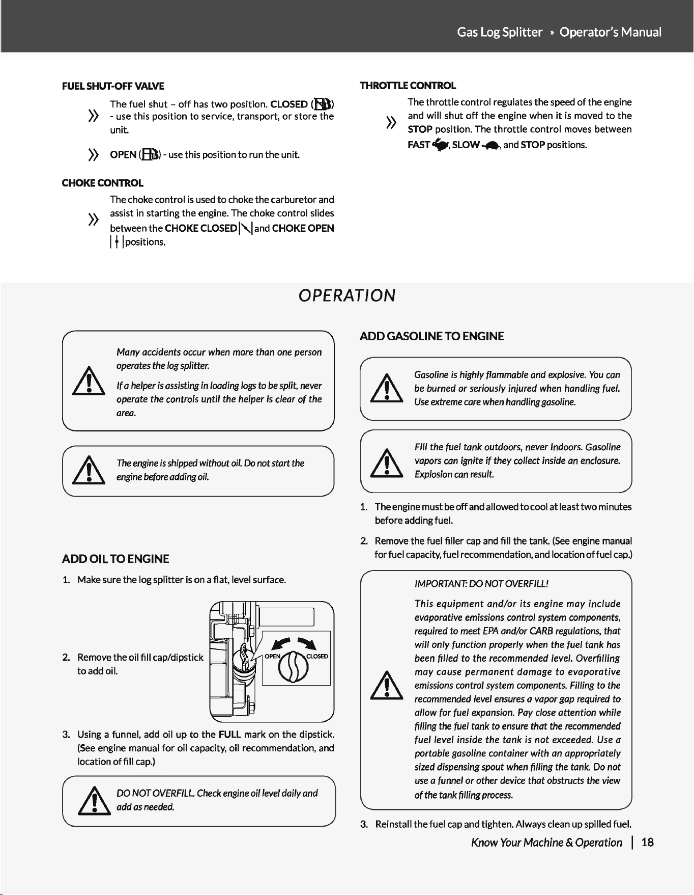
ADD
OIL
TO ENGINE
1. Make sure
the
log
splitter
is on a flat, level surface.
2. Remove
the
oil fill cap/dipstick
to
add oil.
3. Using a funnel, add oil up
to
the
FULL mark on
the
dipstick.
(See
engine manual
for
oil capacity, oil recommendation, and
location
of
fill cap.)
.A\
DO
NOT
OVERFILL.
Check
engine
oil
level
daily
and
~
add
as
needed.
ADD
GASOLINE TO ENGINE
Gasoline
is
highly
flammable
and
explosive.
You
can
be
burned or seriously injured
when
handling
fuel.
Use
extreme
care
when
handling
gasoline.
Fill
the
fuel tank outdoors,
never
indoors.
Gasoline
vapors
can
ignite
if
they collect
inside
an
enclosure.
Explosion
can
result.
1. The engine must be
off
and allowed
to
cool
at
leasttwo
minutes
before adding fuel.
2. Remove
the
fuel filler cap and fill the tank.
(See
engine manual
for
fuel capacity, fuel recommendation, and location
of
fuel
cap.)
IMPORTANT:
DO
NOT
OVERFILL!
This equipment and/or its engine may include
evaporative
emissions
control
system
components,
required
to
meet
EPA
and/or
CARB
regulations,
that
will only function properly
when
the fuel tank
has
been
filled to the
recommended
level.
Overfilling
may cause permanent damage
to
evaporative
emissions
control
system
components.
Filling to
the
recommended
level
ensures
a
vapor
gap
required
to
allow (or fuel
expansion.
Pay
close
attention while
filling
the
fuel
tank to
ensure
that
the
recommended
fuel/eve/ inside the tank
is
not
exceeded.
Use
a
portable gasoline container with
an
appropriately
sized
dispensing
spout
when
filling
the
tank.
Do
not
use
a
funnel
or other
device
that obstructs
the
view
of
the
tank filling
process.
3. Reinstall
the
fuel cap and tighten. Always clean up spilled fuel.
Know
Your
Machine
& Operation I 18
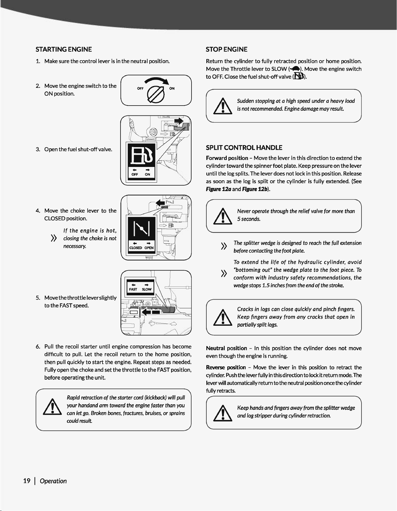
STARTING
ENGINE
1.
Make sure the control lever
is
in
the
neutral position.
( ,
..
J
2
~:'~~~:~g;ne
,.,;toh
jo
the
l._
__
O_F_F
_@
____
ON---
3.
Open
the
fuel shut-off valve.
4. Move the choke lever
to
the
CLOSED
position.
»
If
the
engine is
hot,
closing
the
choke
is
not
necessary.
5.
Movethethrottleleverslightly
to
the
FAST
speed.
6.
Pull the recoil starter until engine compression
has
become
difficult
to
pull. Let
the
recoil return
to
the home position,
then pull quickly
to
start
the engine. Repeat steps
as
needed.
Fully open the choke and set the
throttle
to
the
FAST
position,
before operating
the
unit.
19 I Operation
Rapid
retraction
of
the
starter
cord
(kickback)
will pull
your
handand
arm
toward
the
engine
faster
than
you
can
let
go.
Broken
bones,
fractures,
bruises,
or
sprains
could
result.
STOP
ENGINE
Return the cylinder
to
fully
retracted position
or
home position.
Move the Throttle lever
to
SLOW
(~).
Move the engine switch
to
OFF.
Close the fuel shut-off valve
dBI)).
Sudden
stopping at a
high
speed
under
a
heavy
load
is
not
recommended.
Engine
damage
may
result.
SPLIT
CONTROL HANDLE
Forward position - Move
the
lever in this direction
to
extend the
cylinder toward the spinner
foot
plate. Keep pressure on
the
lever
until the log splits. The lever does
not
lock in this position.
Release
as
soon
as
the log
is
split
or
the cylinder
is
fully
extended.
(See
Fipre
12a and fisure 12b).
»
»
Never
operate
through
the
relief
valve
for
more
than
Sseconds.
The
splitter
wedge
is
designed
to
reach
the
full
extension
before
contacting
the
foot
plate.
To
extend the life of the hydraulic cylinder, avoid
"bottoming out" the
wedge
plate to the
foot
piece.
To
conform with industry safety recommendations, the
wedge
stops
1.5
inches
from
the
end
of
the
stroke.
Cracks
in
logs
can
close
quickly and pinch
fmgers.
Keep
fingers away
from
any cracks
that
open in
partially split
logs.
Neutral position - In this position the cylinder does
not
move
even though the engine
is
running.
Reverse
position - Move the lever
in
this position
to
retract the
cylinder.
Push
the lever fully
in
this direction
to
lock
it
return
mode.
The
lever will automatically return
to
the neutral position once the cylinder
fully retracts.
~
Keep
hands
and
fingers
away
from
the
splitter
wedge
Lll
and
log
stripper during cylinder retraction.
Forward
Figure 12a
//
Reverse Position
,:_:~
+--Neutral
Position
'"
FonNa<d Position
Figure12b
STUCK
LOG
PROCEDURE
If
a log
does
not split completely
and
becomes stuck
on
the wedge,
never attempt
to
remove
it
by modifying the splitter
or
adding
attachments
to
the splitter.
Move the control lever
to
the
Reverse
positon
and
allow the
cylinder
to
retract until the stuck log contacts the stripper plates.
Continue
to
retract the cylinder until the log
is
dislodged from the
wedge.
Do
not
use
the
unit
if
the
stripper
plates
are
bent or
damaged.
Bent
or
damaged
stripper
plates
must
be
repaired
or
replaced
before
use.
Gas
Log Splitter » Operator's Manual
CONVERSION
BETWEEN
HORIZONTAL
SPLITTING
POSITION
AND
VERTICAL
SPLITTING
POSITION
Horizontal Beam Lock
llffflfJ.l.i!fihl!ffUI.l.
Lifting Handle
Operation I
20
TRANSPORTING
MOVING
BY HANDS
~
The
log splitter
is
heavy.
It
can crush and
cause
~
serious
injury
if
it
rolls out of control or tips
over.
Follow
the
instructions
below
for
safely moving
the
log splitter.
1. Make sure
the
log
splitter
is
locked in
the
horizontal position
with
latch rod before moving.
~
Make
sure
the
log
splitter
engine
is
off,
Never
move
~
the
log
splitter with its
engine
running.
2.
Turn
the
fuel
shut-off
valve
to
the
OFF position. This prevents
carburetor
flooding and reduces
the
chance
of
fuel leakage.
Refer
to
the
engine manual
for
fuel valve location.
3. Lock
the
support
leg in
the
DOWN
position before you move
the
log splitter.
4. Move
the
log
splitter
by
hand
to
desired
work
site.
~
Do
not
move
the
log
splitter
up
or
down
hills by
hand.
~
Never
allow
anyone
to sit or
ride
on
the
log
splitter.
~
Never
transport
cargo
or
wood
on
the
log
splitter.
TOWING
BY VEHICLE
1. Turn the fuel shut-off valve off.
This prevents fuel from flooding
the engine.
OFF
ON
2.
Check
the
tires
to
ensure
they
are
fully
inflated
to
30
PSI
for
proper
functionality.
~
Do not overinflate tires.
Serious
injury
can
occur
if
~
tire
explodes.
21 I
Transporting
3.
Make sure hitch
is
in good
working
order.
4.
Check safety chains. Two safety chains must be used
while
towing. Cross safety chains under
the
coupler, allowing
only
enough slack
for
vehicle turns.
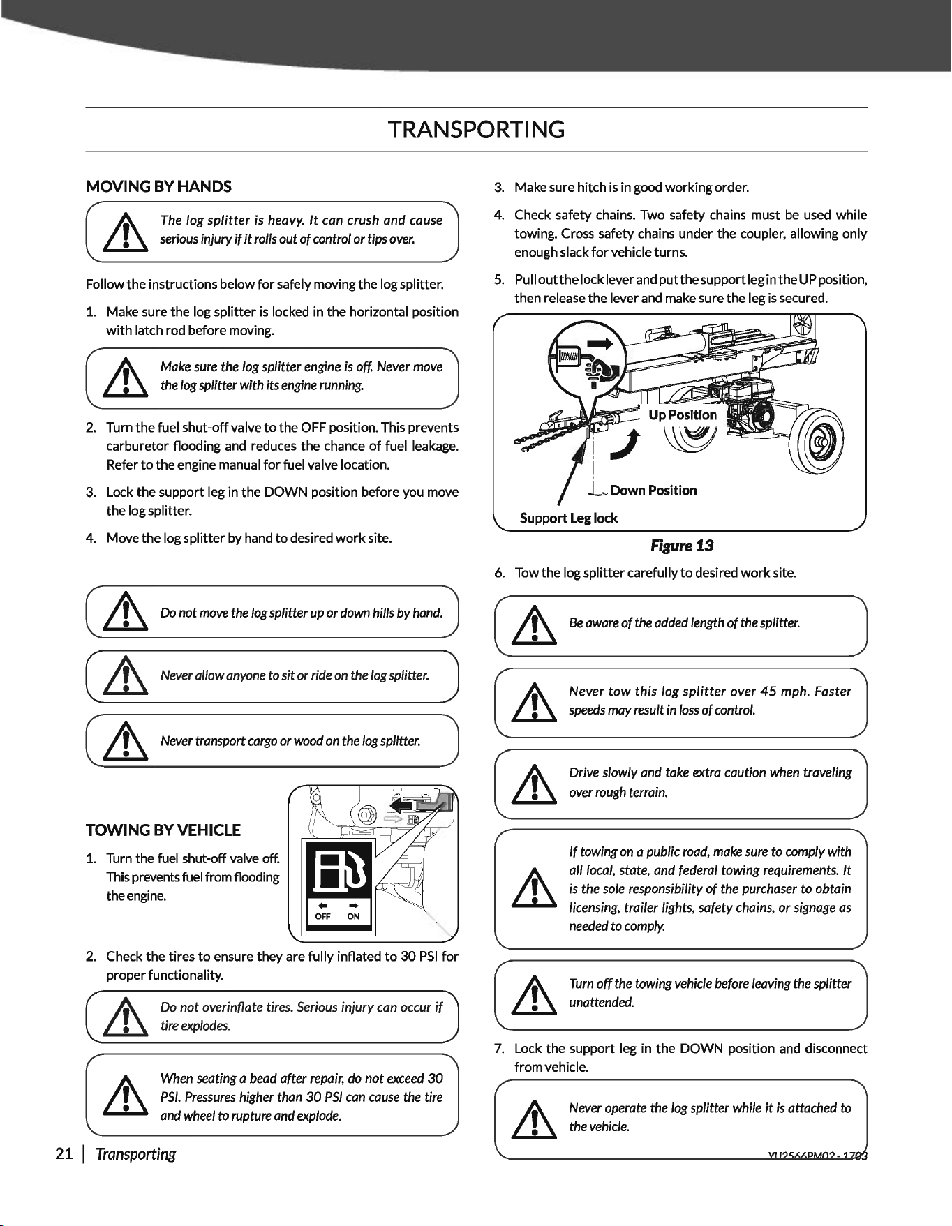
5.
Pu
II
out
the
lock lever and
put
the
support leg in
the
UP position,
then release
the
lever and make sure
the
leg is secured.
ll
Down
Position
Support
Leg
lock
Figure
13
6. Tow
the
log
splitter
carefully
to
desired
work
site.
~
Be
aware
of
the
added
length
of
the
splitter.
Never tow this log
splitter
over
45
mph. Faster
speeds
may
result
in
loss
of control.
Drive slowly and
take
extra caution
when
traveling
over
rough
terrain.
If
towing
on
a public
road,
make
sure
to comply with
all
local,
state, and federal towing requirements.
It
is
the
sole
responsibility
of
the
purchaser to obtain
licensing, trailer lights, safety
chains,
or
signage
as
needed
to
comply.
~
Turn
off
the
towing
vehicle
before
leaving
the
splitter
~
unattended.
7.
Lock
the
support
leg in
the
DOWN
position and disconnect
from
vehicle.
~
Never
operate
the
log
splitter while
it
is
attached
to
~
the
vehicle.
Gas
Log Splitter » Operator's Manual
MAINTENANCE
Inspect and maintain
the
log splitter before each
use.
If
the
log
splitter
has
been
used
previously,
it
must
be
inspected and
maintained before each subsequent
use.
Always shut
off
the engine and relieve system pressure before
inspecting, cleaning, adjusting,
or
repairing the splitter. Relieve
system pressure by moving the split control lever back and
forth
several times.
Remove debris from the engine, muffler,
and
moving parts. Debris
on
a
hot
engine
can
be
a fire hazard. Clean debris and chaff from the
engine cylinder
head,
cylinder
head
fins, blower housing rotating
screen, and muffler
areas.
~
Avoid
contact
with
hot
muffler.
Debris
on
moving
parts
can
cause
excess
wear.
Clear
debris
from
the
slide
beam,
wedge,
and
end
plate.
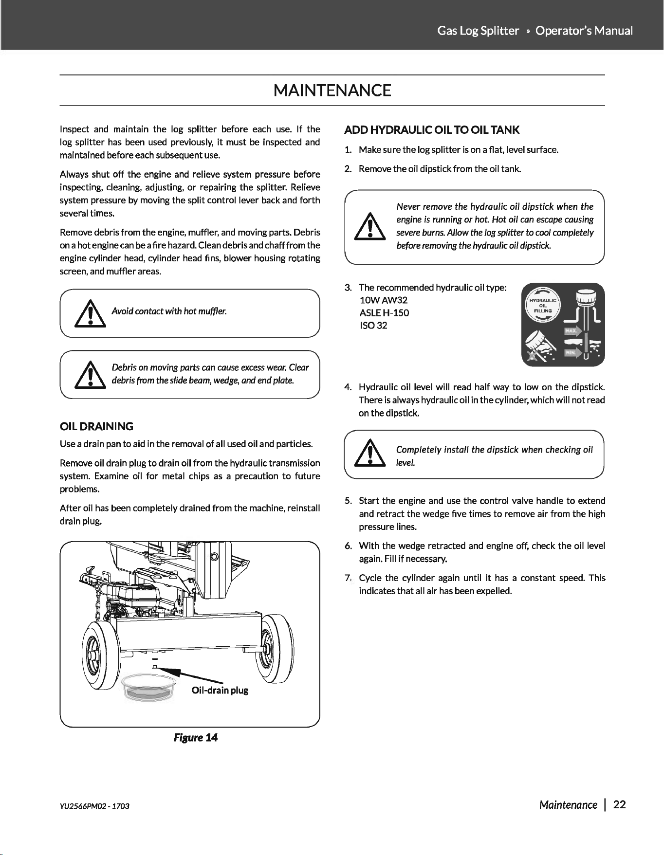
OIL
DRAINING
Use a drain pan
to
aid in the removal
of
all
used
oil and particles.
Remove oil drain plug
to
drain oil from
the
hydraulic transmission
system. Examine oil
for
metal chips
as
a precaution
to
future
problems.
After
oil
has
been completely drained from the machine, reinstall
drain plug.
'(~
~npluo
Figure
14
YU2566PM02- 1703
ADD
HYDRAULIC
OIL
TO
OIL
TANK
1.
Make sure the log splitter
is
on a flat, level surface.
2.
Remove the oil dipstick from the oil tank.
Never
remove
the
hydraulic
oil
dipstick
when
the
engine
is
running
or
hot.
Hot
oil
can
escape
causing
severe
burns.
Allow
the
log
splitter
to
cool
completely
before
removing
the
hydraulic
oil
dipstick.
3.
The recommended hydraulic oil type:
10WAW32
ASLEH-150
15032
4. Hydraulic oil level will read half way
to
low
on
the dipstick.
There
is
always hydraulic oil in
the
cylinder, which will
not
read
on the dipstick.
~
Completely install the dipstick
when
checking
oil
~level.
5.
Start the engine and
use
the control valve handle
to
extend
and retract the wedge five times
to
remove air from the high
pressure lines.
6.
With
the wedge retracted and engine off, check the oil level
again. Fill
if
necessary.
7.
Cycle the cylinder again until
it
has
a constant speed. This
indicates
that
all air
has
been expelled.
Maintenance I 22
STORAGE
Follow the instructions below
for
storing
your
log splitter between
uses.
1.
Retract the wedge completely
to
keep the rod protected from
corrosion.
2.
Allow
the
machine
to
coolS minutes before storing.
3.
Clear the debris from the beam, wedge, and end plate. Use
a damp cloth
to
clear exterior surfaces
of
the engine and log
splitter.
Use
a soft bristle brush
to
remove
excess
dirt
and oil.
Use
an
air compressor (25
PSI)
to
clear
dirt
and small debris.
Wipe
the beam, wedge, and all metal parts
with
an
oil rag
to
prevent corrosion.
~
Never
spray
the
engine
or
log
splitter with a
pressure
Lll
washer.
Water
can
contaminate
the
fuel
system
and
can
enter
the
engine
and
damage
the
engine.
4.
Refer
to
the engine manual
for
proper engine storage instructions.
Gasoline
can
become
stale
when
stored over
30
days.
Stale fuel
can
cause
acid and
gum
deposits
that
form
in
the
fuel
system
or
on
carburetor
parts.
~
For
engine
fuel
that
is
stored
less
than
30
days,
add
Lll
a fuel stabilizer to
keep
the
fuel
fresh.
Turn
the
fuel
valve
lever
to
the
off
position.
If
fuel
is
stored
over
30
days,
then
drain
the
fuel
tank
as
stated
in
the
engine
manual.
23 I Maintenance &
Storage
Always
drain
fuel
from
the
tank
in
an
outdoor,
well-
ventilated
area.
~
Stay away from
sources
of
heat,
flame,
or sparks
Lll
while
handling
fuel.
Clean
up
fuel
spills
immediately.
5.
Store the log
splitter
in a location away from corrosive
materials, sources
of
heat, open flames, sparks,
or
pilot
lights.
Never store the
log
splitter inside
where
there
is
a
source
of
heat or
an
open
flame,
spark,
or
pilot
light,
such
as
a water
heater,
space
heater,
furnace,
~
clothes
dryer,
or other
gas
appliance.
EVEN
IF
the
log
Lll
splitter's
fuel
tank
is
empty,
residual
gasoline
vapors
could
ignite.
Never
store
the
log
splitter
near
fertilizer or
any
other
corrosive
material.
6.
Store gasoline in a cool,
dry
place in a UL listed
tightly
sealed
container.
Gasoline
vapors
can
ignite
if
they collect
inside
an
enclosure
and
explosion
can
result.
YU2566PM02- 1703
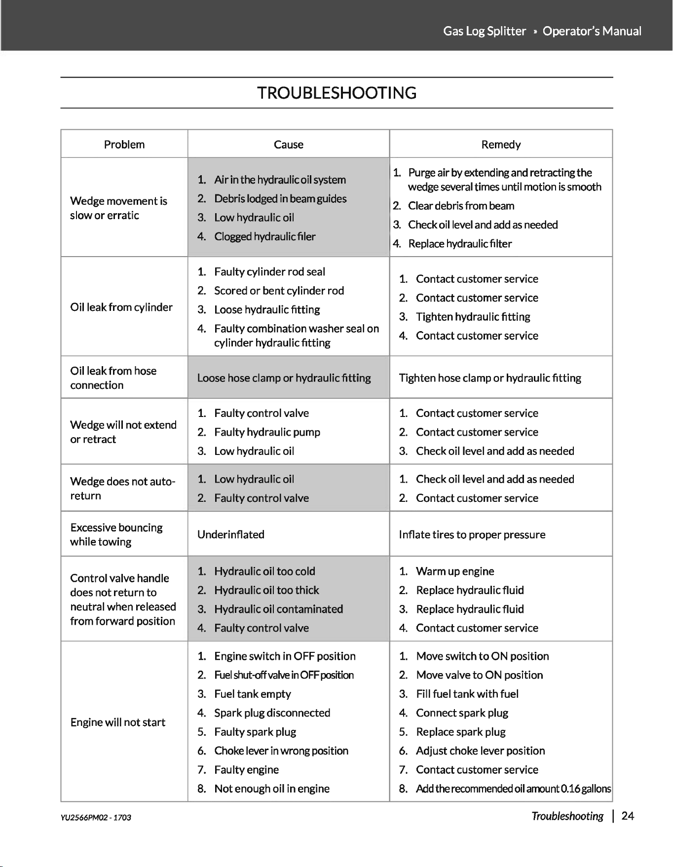
Problem
Wedge movement
is
slow
or
erratic
Oil leak
from
cylinder
Oil leak
from
hose
connection
Wedge
will
not
extend
or
retract
Wedge does
not
auto-
return
Excessive bouncing
while
towing
Control valve handle
does
not
return
to
neutral when released
from
forward position
Engine
will
not
start
--
YU2566PM02- 1703
Gas
Log Splitter » Operator's Manual
TROUBLESHOOTING
Cause
Remedy
~
1.
Purge air by extending
and
retracting the
wedge several times until motion
is
smooth
1.
Airinthehydraulicoilsystem
2.
Debris lodged in
beam
guides
2.
Clear debris from
beam
3.
Low hydraulic oil
3.
Check oil level
and add
as
needed
4. Clogged hydraulic filer
4.
Replace
hydraulic filter
1.
Faulty cylinder rod seal
1.
Contact customer service
2.
Scored
or
bent cylinder rod
2.
Contact customer service
3.
Loose hydraulic
fitting
3.
Tighten hydraulic
fitting
4. Faulty combination washer seal on
4. Contact customer service
cylinder hydraulic
fitting
Loose hose clamp
or
hydraulic
fitting
Tighten hose clamp
or
hydraulic
fitting
1.
Faulty control valve
1.
Contact customer service
2.
Faulty hydraulic pump
2.
Contact customer service
3.
Low hydraulic oil
3.
Check oil level and add
as
needed
1.
Low hydraulic oil
1.
Check oil level and add
as
needed
2.
Faulty control valve
2.
Contact customer service
Underinflated
Inflate tires
to
proper pressure
1.
Hydraulic oil
too
cold
1.
Warm up engine
2.
Hydraulic oil
too
thick
2.
Replace hydraulic fluid
3.
Hydraulic oil contaminated
3.
Replace hydraulic fluid
4.
Faulty control valve
4.
Contact customer service
1.
Engine switch in OFF position
1.
Move switch
to
ON position
2.
Fuel
shut-offvalve
in
OFF
position
2.
Move valve
to
ON position
3.
Fuel
tank
empty
3.
Fill fuel
tank
with
fuel
4.
Spark plug disconnected
4.
Connect spark plug
5.
Faulty spark plug
5.
Replace spark plug
6.
Choke lever in wrong position
6.
Adjust choke lever position
7.
Faulty engine
7.
Contact customer service
8.
Not
enough oil in engine
8.
Add
the
recommended
oil
amount
0.16
gallons
Troubleshooting
I
24
~
~
~
0
V)
~
~
11
73
74
72 66
lJI
93
15
106
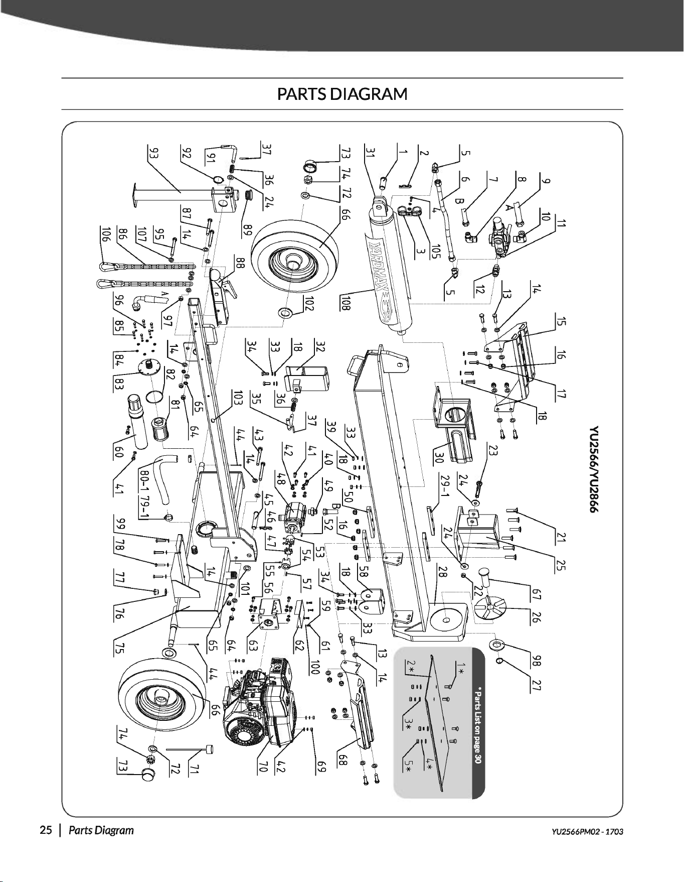
YU2566/YU2866
• Parts List on page
30
----=--=
~
2*1;~~
R
....
~
'()
'()
~
E
E
~
i5
t!
~
1.0
N

No.
Description
1
Pin
35x59
Qty
1
2 Bridge
Pin
1
3
Hose
Clamp 40 2
4
Hex5ocketHeadCapScrewM6x20
1
5 Right-Angle Fitting 2
6 Welded
Hose
1
7 High Pressure Supply
Hose
1
8 Right-Angle Fitting 1 1
9 Low Pressure Return Hose 1
10 Right-Angle Fitting 2 1
11 Control Valve 1
12 Straight Fitting 1
13 Bolt M12x35 8
14 Flat Washer 12
15
Log
Cradle-Left
16
LockNutM12
17 Bolt M10x35
18 Washer10
19-1 Discontinued
22
1
14
4
14
N/A
20 Discontinued N/A
21
CrossRecessedHeadScrewM12x55
6
22
Lock
Nut
M14 1
23 Bolt 14x90 1
24 Washer14
25 Wedge
26
Log
Spinner
27 Circlip 29
28
Beam
Weldment
29-1 Guide Slide
30
Log
Stripper Weldment
31 Cylinder
32
Beam
Lock
Bracket
33 Spring Washer 10
34 Bolt M10x25
35 Latch
Rod
36 Pressure Spring
YU2566PM02- 1703
4
1
1
1
1
2
1
1
1
10
6
1
2
YU2566/YU2866
PARTS
LIST
No.
Description
37 Pin6x40
Qty
2
38 Discontinued N/A
39
NutM10
4
40 Spring Washer 8 12
41 Bolt M8x20 6
42 Washer 8 18
43 Bolt M 12x90 2
44 Cotter
Pin
4x50 2
45
Beam
Pivot
Pin
20x110 1
46 Bridge
Pin
1
47 Elastic Spider Block 1
~
G~r~mp
1
49 Outlet Connector
of
Pump
1
50 Retainer Slide
51 Discontinued
52 Key3x25
2
N/A
1
53 Gear
Pump
Connector Left 1
54 Gear
Pump
Connector Right 1
55 Screw M6x8 4
56 Bolt S/16-24UNF 4
57
Key
3/16x30
58 Pivot Bracket
59 Spring Washer 4
60 Manual
Tube
61 Screw M4x8
1
1
4
1
4
62 Cover
of
Pump
Bracket 1
63
Pump
Bracket 1
64
Nut
M12 4
65 Spring Washer 12 4
66 Tire 2
67 LocatingPiungerofl.ogSpinner 1
68
Log
Cradle-Right 1
69
NutM8
4
70
Engine
1
71 Dipstick 1
72 Whee1Washer22 2
Gas
Log Splitter » Operator's Manual
No.
Description
73 DustCap
74 Axle
Nut
M22
75 TankAssembly
76 Washer20
77 Drain
Plug
78 Bolt M8x40
79-1 Clamp 25-38
80-1 Suction
Hose
81 Return Oil Filter
82 0-Ring D81x3.1
83
Flange
of
Filter
84 Washer6
85 Bolt M6x16
86 SafetyChain
87 Bolt M 12x80
88 2" Ball Coupler Hitch
89
Pipe
Plug
90 Discontinued
91 Latch
Rod
92 Circlip 34
93 Support
Leg
Weldment
94 Discontinued
95
Bolt M10x85
96 Washer6
97
NutM10
98
Big
Washer 30
99 WasherS
100 Washer4
101 FlatWasher20
102 Anti-Dust Washer
103 TowBar
104 Discontinued
105
Hose
Clamp 45
106
SafetyCiasp
107 Washer 10
108
Logo
Decal
on Cylinder
Qty
2
2
1
1
1
4
2
8
1
1
1
6
6
2
2
1
1
N/A
1
1
1
N/A
1
7
1
1
4
4
1
2
1
N/A
1
2
4
2
Parts
List 26

YU3066
15 16
17 18
93
106
• Parts List
on
page
30
4*
2*~~
~e;::~~~~·
_
_._-<d
;•;!L-~--.d
R
....
~
'()
'()
~
E
e
~
i5
t!
~
""
N

No.
Description
1
Pin
35x59
Qty
1
2 Bridge
Pin
1
3
Hose
Clamp 40 2
4
Hex
Socket
Head
Cap
Screw
M6x20
1
5 Right-Angle Fitting 2
6 Welded
Hose
1
7 High Pressure Supply
Hose
1
8 Right-Angle Fitting 1 1
9 Low Pressure Return
Hose
1
10 Right-Angle Fitting 2
11 Control Valve
12 Straight Fitting
13 Bolt M12x35
14 Flat Washer 12
15
Log
Cradle-Left
16
LockNutM12
17 Bolt M10x35
18 Washer10
19-1 Discontinued
20 Discontinued
1
1
1
8
24
1
14
4
18
N/A
N/A
21
Cross
Recessed
Head
Screw
M12x55
6
22
Lock
Nut M14 1
23 Bolt 14x90 1
24 Washer14
25
Wedge
26
Log
Spinner
27 Circlip 29
28
Beam
Weldment
29-1 Guide Slide
30
Log
Stripper Weldment
31 Cylinder
32
Beam
Lock
Bracket
33 Spring Washer 10
34 Bolt M10x25
35
Latch
Rod
36 Pressure Spring
YU2566PM02- 1703
4
1
1
1
1
2
1
1
1
14
6
1
1
YU3066
PARTS
LIST
No.
Description
37 Pin6x40
Qty
2
Gas
Log Splitter » Operator's Manual
No.
Description
74 Axle Nut M22
38 Discontinued
39
NutM10
N/A
75
TankAssembly
Qty
2
1
1
1
4
2
1
1
1
1
6
6
2
2
1
1
8 7 6 Washer 20
40 Spring Washer 8
41 Bolt M8x20
4 77 Drain
Plug
6 78-1 Bolt M10x45
42 WasherS 10 79-1 Clamp 25-38
43 Bolt M 12x90
44 Cotter
Pin
4x50
2 80-1 Suction
Hose
2 81 Return Oil Filter
45
Beam
Pivot
Pin
20x110
1 82 0-Ring D81x3.1
46 Bridge
Pin
1
47 Elastic Spider Block 1
48 Gear
Pump
1
49 Outlet Connector
of
Pump
1
50 Retainer
Slide
2
51 Discontinued N/A
52 Key3x25 1
53 Gear
Pump
Connector Left 1
54 Gear
Pump
Connector Right 1
55
Screw M8x10 2
56 Bolt S/16-24UNF 4
57 Key1/4x50
58 Pivot Bracket
59 Spring Washer 5
60 Manual
Tube
61 Screw M5x10
1
1
4
1
4
62 Cover
of
Pump
Bracket 1
63
Pump
Bracket 1
64 Nut M12 4
65
Spring Washer 12 4
66 Tire 2
67
L..ocatingPiungerofl.ogSpinner
1
68
Log
Cradle-Right 1
69 WasherS 4
70
Engine
71 Dipstick
72 Whee1Washer22
73 DustCap
1
1
2
2
83
Flange
of
Filter
84 Washer6
85
Bolt M6x16
86 Safety Chain
87 Bolt M 12x80
88 2"
Ball
Coupler Hitch
89
Pipe
Plug
90 Discontinued
91
Latch
Rod
92 Circlip 34
93
Support
Leg
Weldment
94 Discontinued
95
Bolt M10x85
96
Washer6
97
NutM10
98
Big
Washer 30
N/A
1
1
1
N/A
1
7
1
1
99
Discontinued N/A
100 Discontinued N/A
101 Flat Washer 20 1
102 Anti-Dust Washer 2
103 Washer 10 8
104 Discontinued N/A
105
Hose
Clamp 45 1
106 Safety
Clasp
2
107 Screw M6x8 2
108 TowBar 1
109
Logo
Decal
on
Cylinder 2
Parts
List 28
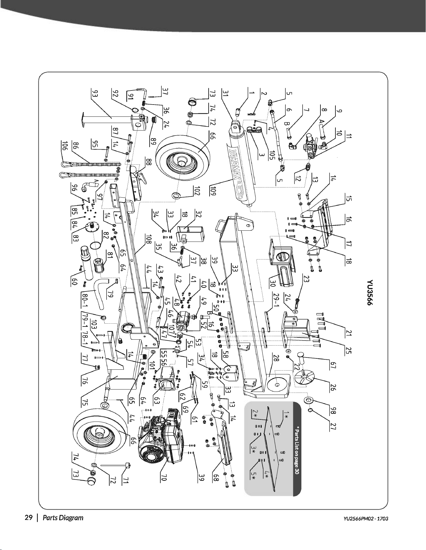
YU3566
17 18
14
~·
93
106
• Parts List
on
page
30
'IT
'IT
4*
2*~~
R
....
~
'()
'()
~
E
e
~
i5
t!
~
o-
N

No.
1
2
3
4
5
Description Qty
Pin
35x59 1
Bridge
Pin
1
Hose Clamp 40 1
Hex
Socket
Head
Cap
Screw
M6x20
1
Right-Angle Fitting 2
6 Welded
Hose
1
7 High Pressure Supply Hose 1
8 Right-Angle Fitting 1 1
9 Low Pressure Return
Hose
1
10 Right-Angle Fitting 2
11 Control Valve
12 Straight Fitting
13 Bolt M 12x35
14 Flat Washer 12
15
Log
Cradle-Left
16
Lock
Nut M12
17 Bolt M10x35
18 Washer 10
19-1 Discontinued
20 Discontinued
1
1
1
8
24
1
14
4
18
N/A
N/A
21
Cross
Recessed
Head
Screw
M12x55
8
22
Lock
Nut M14 1
23 Bolt 14x95 1
24 Washer 14 4
25 Wedge
26 LogSpinner
27 Circlip 29
28
Beam
Weldment
29-1 GuideSiide
30
Log
Stripper Weldment
31 Cylinder
32
Beam
Lock
Bracket
33 Spring Washer 10
34 Bolt M 10x25
35 Latch
Rod
1
1
1
1
2
1
1
1
14
6
1
Gas
Log Splitter » Operator's Manual
YU3566
PARTS
LIST
No.
Description
Qty
No.
Description
40 Spring Washer 8 4 79-1 Clamp 25-38
41 Bolt M8x20
6 80-1 Suction
Hose
42 WasherS 8 81 Return Oil Filter
43 Bolt M 12x90
44 Cotter
Pin
4x50
2 82 0-Ring D81x3.1
2 83
Flange
of
Filter
45
Beam
Pivot
Pin
20x110
46 Bridge
Pin
1 84 Washer6
1 85 Bolt M6x16
47 Elastic Spider Block
48 GearPump
1 86 SafetyChain
1 87 Bolt M 12x80
49 Outlet Connector
of
Pump
1
50 Retainer Slide 2
51 Discontinued N/A
52 Key3x25 1
53 Gear
Pump
Connector Left 1
54 Gear
Pump
Connector Right 1
55 Screw M8x10 2
56 Bolt 5/16-24UNF 4
57 Key1/4x50
58 Pivot Bracket
59 Spring Washer 5
60 Manual
Tube
61 Screw M5x10
62 Cover
of
Pump
Bracket
63
Pump
Bracket
64
NutM12
65 Spring Washer 12
66 Tire
1
1
4
1
4
1
1
4
4
2
67 LocatingPiungerofl.ogSpinner 1
68
Log
Cradle-Right 1
69 WasherS 4
88 2" Ball Coupler Hitch
89
Pipe
Plug
90 Discontinued
91 Latch
Rod
92 Circlip 34
93 Support
Leg
Weldment
94 Discontinued
95
Bolt M10x85
96 Washer6
97
NutM10
98
Big
Washer 30
99 Discontinued
100 Discontinued
101 Flat Washer 20
102 Anti-Dust Washer
103 Washer 10
104 Discontinued
105
Hose
Clamp 45
106 Safety
Clasp
107 Screw M6x8
108 TowBar
Qty
2
1
1
1
1
6
6
2
2
1
1
N/A
1
1
1
N/A
1
7
1
1
N/A
N/A
2
2
8
N/A
1
2
2
1
70
Engine
71 Dipstick
109
Logo
Decal
on Cylinder 2
72 Whee1Washer22
73 DustCap
74 Axle
Nut
M22
OPTIONAL
LOG
TABLE
No.
Description Qty
1 * Bolt M 10x25 4
36 Pressure Spring
37 Pin6x40
1 75
Tank
Assembly
1
1
2
2
2
1
1
1
4
2* LogTable 1
4
4
4
38 Discontinued
39
NutM10
2 76 Washer 20
N/A 77 Drain
Plug
8 78-1 Bolt M 10x45
3* Flat Washer 10
4* Spring Washer 10
5* Nut M10