
Microwave Oven
Installation manual
ME11
*
7510
**
/ ME11
**
7510
**
/ ME11
*
7710
**
DE68-04709D-00_IM_ME11F7510MT_AA_EN.indd 1DE68-04709D-00_IM_ME11F7510MT_AA_EN.indd 1 2024-11-07 오후 3:28:582024-11-07 오후 3:28:58
2 English
Before you begin
Before you beginContents
Before you begin 2
General information 3
Important safety instructions 3
Electrical requirements 3
Hood exhaust 4
Damage - Shipment/Installation 6
Parts included 6
Tools you will need 7
Mounting space 7
Dimension of Product 8
Step-by-step installation guide 9
Step 1. Placement of the mounting plate 9
Step 2. Ventilation types (choose A, B or C) 12
Step 3. Installation 15
Step 4. Before you use your microwave 19
Before you begin
ABOUT THIS MANUAL
READ THESE INSTRUCTIONS COMPLETELY AND CAREFULLY.
Important
• Save these instructions for local inspector’s use.
• Observe all governing codes and ordinances.
Important note to the installer
Be sure to leave these instructions with the Consumer.
Important note to the consumer
Keep these instructions with your user manual for future reference.
Skill level
Installation of this appliance requires basic mechanical and electrical skills.
Proper installation is the responsibility of the installer
Product failure due to improper installation is not covered under the
Warranty
DE68-04709D-00_IM_ME11F7510MT_AA_EN.indd 2DE68-04709D-00_IM_ME11F7510MT_AA_EN.indd 2 2024-11-07 오후 3:28:582024-11-07 오후 3:28:58
English 3
General information
General information
IMPORTANT SAFETY INSTRUCTIONS
This product requires a three-prong grounded outlet. The installer must perform a ground
continuity check on the power outlet box before beginning the installation to ensure that the
outlet box is properly grounded. If not properly grounded, or if the outlet box does not meet
electrical requirements noted (under ELECTRICAL REQUIREMENTS), a qualied electrician
should be employed to correct any deciencies.
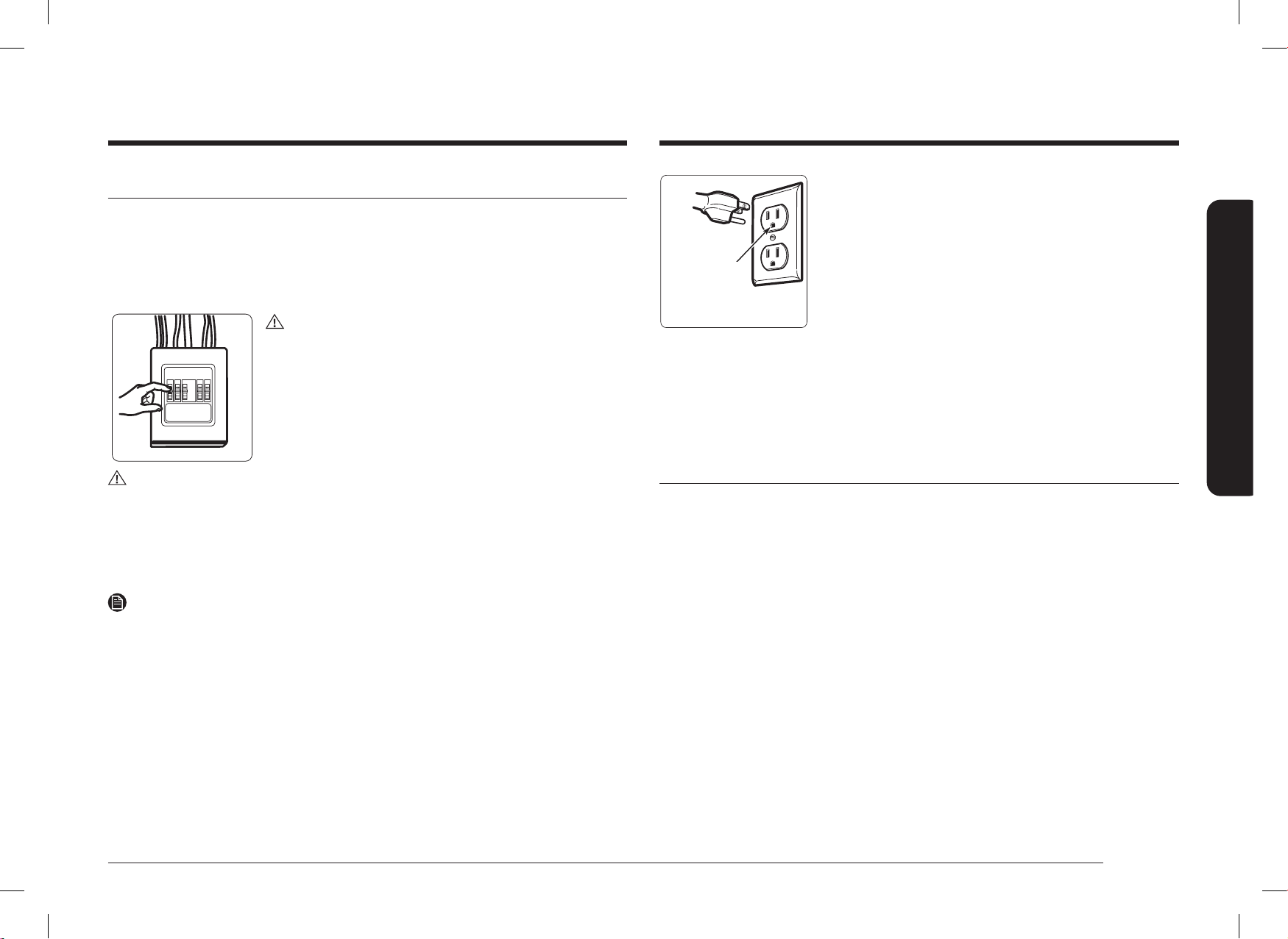
CAUTION
For personal safety, remove the house fuse or open the circuit
breaker before beginning the installation to avoid severe or
fatal shock injury.
CAUTION
• For personal safety, the mounting surface must be capable of supporting the cabinet
load in addition to the added weight of this 69 pound product, plus additional oven loads
of up to 50 pounds or a total weight of 119 pounds.
• For personal safety, do not install this product in cabinetry congured as an island or a
peninsula. The microwave oven must be mounted to BOTH a top cabinet AND a wall.
NOTE
For easier installation and personal safety, we recommend that two people install this
product.
IMPORTANT – PLEASE READ CAREFULLY. FOR PERSONAL SAFETY, THIS
APPLIANCE MUST BE PROPERLY GROUNDED TO AVOID SEVERE OR FATAL
SHOCK.
Insure proper
ground exists
before use.
The power cord of this appliance is equipped with a three-prong
(grounding) plug which mates with a standard three-prong
(grounding) wall receptacle to minimize the possibility of
electric shock hazard from this appliance.
You should have the wall receptacle and circuit checked by a qualied electrician to make
sure the receptacle is properly grounded.
If you have a standard two-prong wall receptacle, it is very important to have it replaced with
a properly grounded three-prong wall receptacle, installed by a qualied electrician.
DO NOT, UNDER ANY CIRCUMSTANCES, CUT, DEFORM OR REMOVE ANY OF THE PRONGS
FROM THE POWER CORD. DO NOT USE WITH AN EXTENSION CORD.
ELECTRICAL REQUIREMENTS
Product rating is 120 volts AC, 60 Hertz. This product must be connected to a supply circuit
of the proper voltage and frequency. Wire size must conform to the requirements of the
National Electrical Code or the prevailing local code for this kilowatt rating. The power supply
cord and plug should be brought to a separate branch circuit single grounded outlet of at
least 15 A and max of 20 A. 20 A is recommended for multifamily buildings. The outlet box
should be located in the cabinet above the microwave oven. The outlet box and supply circuit
should be installed by a qualied electrician and conform to the National Electrical Code or
the prevailing local code.
DE68-04709D-00_IM_ME11F7510MT_AA_EN.indd 3DE68-04709D-00_IM_ME11F7510MT_AA_EN.indd 3 2024-11-07 오후 3:28:582024-11-07 오후 3:28:58
4 English
General information
General information
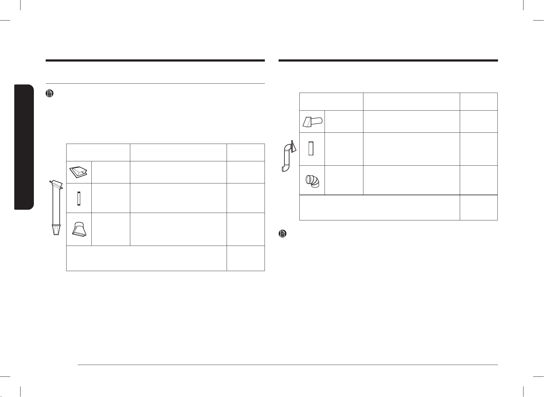
OUTSIDE BACK EXHAUST (EXAMPLE ONLY)
The following chart contains an example of one possible ductwork installation.
DUCT PIECES
EQUIVALENT
LENGTH
x
NUMBER
USED
=
EQUIVALENT
LENGTH
Wall Cap 40 ft. x (1) = 40 ft.
3 Ft. Straight
Duct
(3 ¼˝ x 10˝
Rectangular)
3 ft. x (1) = 3 ft.
90° Elbow 10 ft. x (2) = 20 ft.
Equivalent lengths of duct pieces are based on
actual tests and reect requirements for good
venting performance with any vent hood.
Total
Length
= 63 ft.
NOTE
For back exhaust, care should be taken to align the exhaust with the space between studs, or
the wall should be prepared at the time it is constructed by leaving enough space between
the wall studs to accommodate exhaust.
HOOD EXHAUST
NOTE
Read these next two pages only if you plan to vent your exhaust to the outside. If you plan to
recirculate the air back into the room, proceed to page 12.
OUTSIDE TOP EXHAUST (EXAMPLE ONLY)
The following chart contains an example of one possible ductwork installation.
DUCT PIECES
EQUIVALENT
LENGTH
x
NUMBER
USED
=
EQUIVALENT
LENGTH
Roof Cap 24 ft. x (1) = 24 ft.
12 Ft. Straight
Duct
(6˝ Round)
12 ft. x (1) = 12 ft.
Rectangular-
to-Round
Transition
Adaptor*
5 ft. x (1) = 5 ft.
Equivalent lengths of duct pieces are based on
actual tests and reect requirements for good
venting performance with any vent hood.
Total Length = 41 ft.
IMPORTANT:
If a rectangular-to-round transition adaptor is used, the bottom corners of the damper will
have to be cut to t, using the tin snips, in order to allow free movement of the damper.
DE68-04709D-00_IM_ME11F7510MT_AA_EN.indd 4DE68-04709D-00_IM_ME11F7510MT_AA_EN.indd 4 2024-11-07 오후 3:28:582024-11-07 오후 3:28:58
English 5
General information
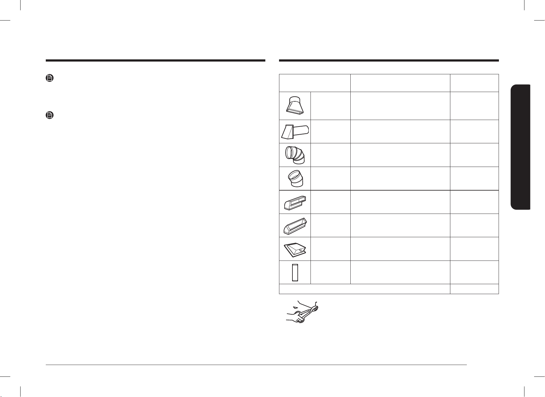
DUCT PIECES
EQUIVALENT
LENGTH
x
NUMBER
USED
=
EQUIVALENT
LENGTH
Rectangular-
to-Round
Transition
Adaptor*
5 ft. x ( ) = ft.
Wall Cap
40 ft. x ( ) = ft.
90 ° Elbow
10 ft. x ( ) = ft.
45 ° Elbow
5 ft. x ( ) = ft.
90 ° Elbow
25 ft. x ( ) = ft.
45 ° Elbow
5 ft. x ( ) = ft.
Roof Cap
24 ft. x ( ) = ft.
Straight Duct 6˝
Round or 3 ¼˝ x
10˝ Rectangular
1 ft. x ( ) = ft.
Total Ductwork = ft.
*IMPORTANT: If a rectangular-to-round transition adaptor is used, the
bottom corners of the damper will have to be cut to t,
using tin snips, to allow free movement of the damper.
Equivalent lengths of duct pieces are based on actual
tests and reect the requirements for good venting
performance with any vent hood.
NOTE
If you need to install ducts, note that the total duct length of 3 ¼˝ x 10˝ rectangular or 6˝
diameter round duct should not exceed 140 equivalent feet.
Outside ventilation requires a HOOD EXHAUST DUCT. Read the following carefully.
NOTE
It is important that venting be installed using the most direct route and with as few elbows as
possible. This ensures clear venting of exhaust and helps prevent blockages. Also, make sure
dampers swing freely and nothing is blocking the ducts.
Exhaust connection:
The hood exhaust has been designed to mate with a standard 3 ¼˝ x 10˝ rectangular duct.
If a round duct is required, a rectangular-to-round transition adaptor must be used. Do not
use less than a 6˝ diameter duct.
Maximum duct length:
For satisfactory air movement, the total duct length of 3 ¼˝ x 10˝ rectangular or 6˝ diameter
round duct should not exceed 140 equivalent feet.
Elbows, transitions, wall and roof caps, etc. present additional resistance to airow and are
equivalent to a section of straight duct which is longer than their actual physical size. When
calculating the total duct length, add the equivalent lengths of all transitions and adaptors
plus the length of all straight duct sections. The chart below shows you how to calculate total
equivalent ductwork length using the equivalent length in feet of some typical ducts.
DE68-04709D-00_IM_ME11F7510MT_AA_EN.indd 5DE68-04709D-00_IM_ME11F7510MT_AA_EN.indd 5 2024-11-07 오후 3:28:582024-11-07 오후 3:28:58
6 English
General information
General information
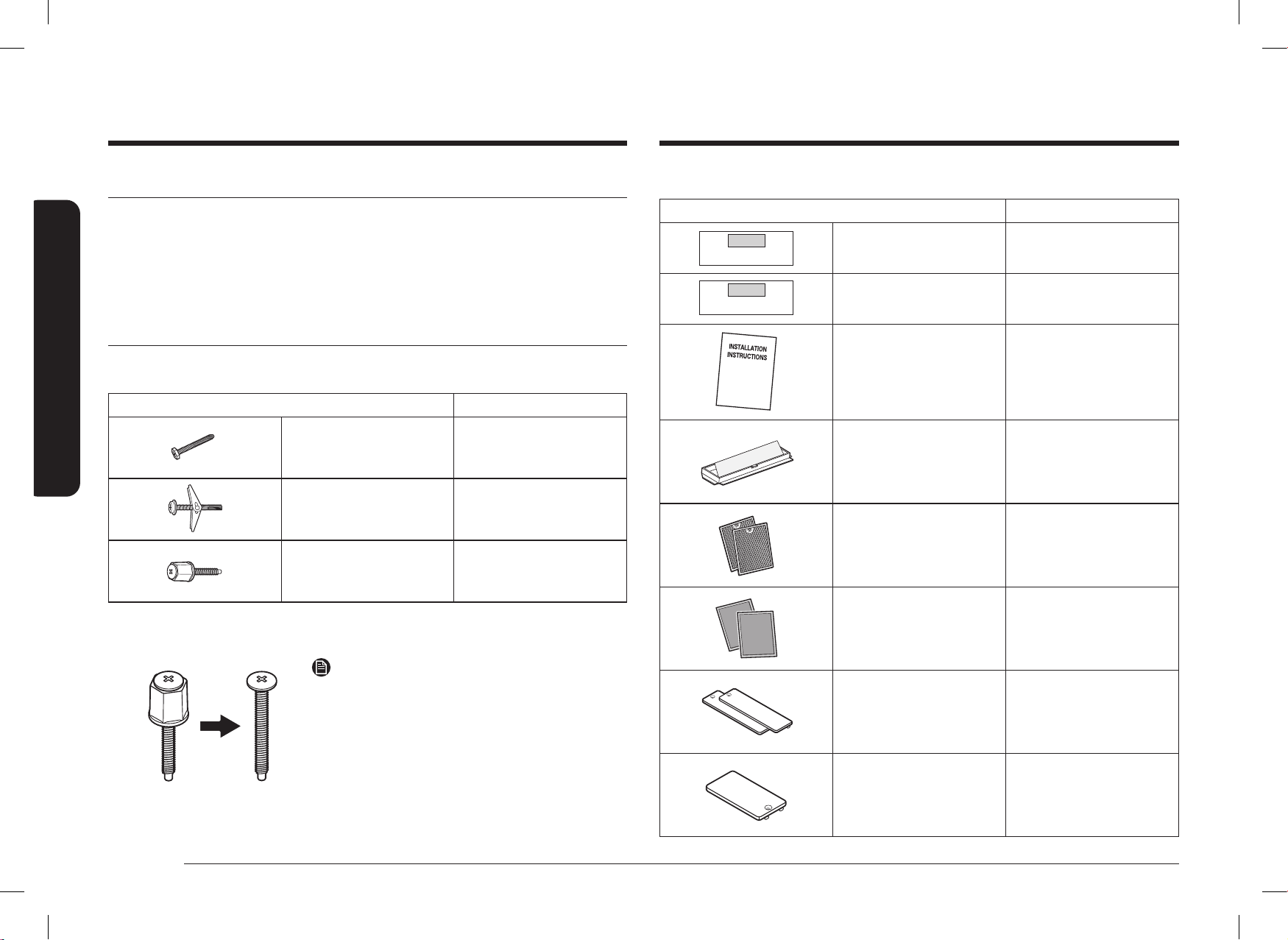
ADDITIONAL PARTS
PART QUANTITY
TOP CABINET TEMPLATE
REAR WALL TEMPLATE
Top Cabinet Template 1
TOP CABINET TEMPLATE
REAR WALL TEMPLATE
Rear Wall Template 1
Installation Instructions 1
Template
INSTALLATION
INSTRUCTIONS
Exhaust Adaptor 1
Separately Packed
Grease Filters
2
Separately Packed
Charcoal Filters
2
Cover Air-Right 2
Cover Air-Left 1
DAMAGE - SHIPMENT/INSTALLATION
• If the unit is damaged in shipment, return the unit to the store in which it was bought for
repair or replacement.
• If the unit is damaged by the customer, repair or replacement is the responsibility of the
customer.
• If the unit is damaged by the installer (if other than the customer), repair or replacement
must be made by arrangement between the customer and installer.
PARTS INCLUDED
HARDWARE PACKET
PART QUANTITY
Template
INSTALLATION
INSTRUCTIONS
Wood Screws 1
Template
INSTALLATION
INSTRUCTIONS
Toggle Bolts
(and wing nuts)
2
Self-aligning
Machine Screws
With Supporter
2
You will nd the installation hardware contained in a packet with the unit. Check to make
sure you have all these parts.
NOTE
If Cabinet Thickness is over 1 ˝, Remove Supporter.
DE68-04709D-00_IM_ME11F7510MT_AA_EN.indd 6DE68-04709D-00_IM_ME11F7510MT_AA_EN.indd 6 2024-11-07 오후 3:28:582024-11-07 오후 3:28:58
English 7
General information
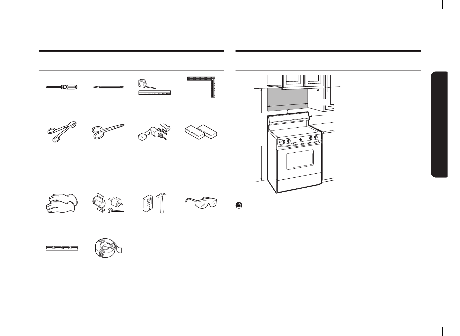
MOUNTING SPACE
24
1
/5˝
30˝
2˝
Bottom edge of the cabinet
needs to be 24
1
/5˝ or more
from the cooking surface.
Backsplash
NOTE
• The space between the cabinets must be 30˝ wide and free of obstructions.
• If you are going to vent your microwave oven to the outside, see the Hood Exhaust
Section for exhaust duct preparation.
• If installing the microwave oven beneath smooth at cabinets, be careful to follow the
instructions on the top cabinet template for power cord clearance.
• The dimensions provided are the minimum required for mounting the microwave oven.
• Minimum 2”: clearance from the top of the range control panel to the bottom of
microwave oven.
TOOLS YOU WILL NEED
#1 and #2 Phillips
screwdriver
Pencil Ruler or tape measure
and straight edge
Carpenter square
(optional)
Tin snips (for cutting
damper, if required)
Scissors (to cut
template, if necessary)
Electric drill with
3
/16˝,
1
/2˝ and
5
/8˝ drill bits
Filler blocks or scrap
wood pieces, if needed
for top cabinet spacing
(used on recessed
bottom cabinet
installations only)
Gloves Saw (saber, hole or
keyhole)
Stud nder or Hammer
(optional)
Safety goggles
Level Duct and masking tape
60˝ or More
from the
Floor to the
Top of the
Microwave
DE68-04709D-00_IM_ME11F7510MT_AA_EN.indd 7DE68-04709D-00_IM_ME11F7510MT_AA_EN.indd 7 2024-11-07 오후 3:28:592024-11-07 오후 3:28:59
8 English
General information
General information
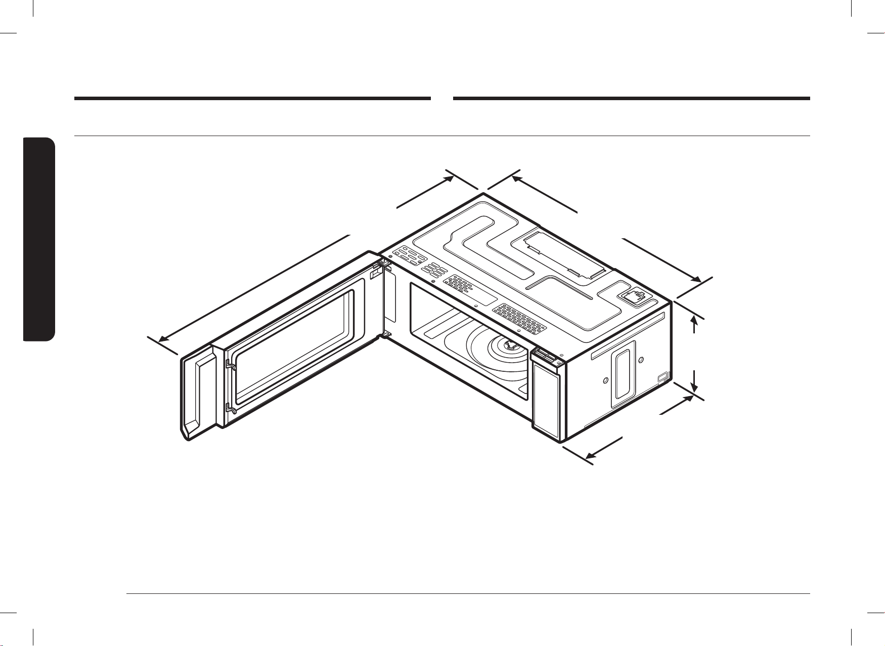
DIMENSION OF PRODUCT
46
11
/16˝
(1185.9mm)
With Plate mounting
29
7
/8˝
(758.8mm)
10
11
/16˝
(272.0mm)
19
3
/16˝
(486.7mm)
With Plate
mounting
DE68-04709D-00_IM_ME11F7510MT_AA_EN.indd 8DE68-04709D-00_IM_ME11F7510MT_AA_EN.indd 8 2024-11-07 오후 3:28:592024-11-07 오후 3:28:59
English 9
Step-by-step installation guide
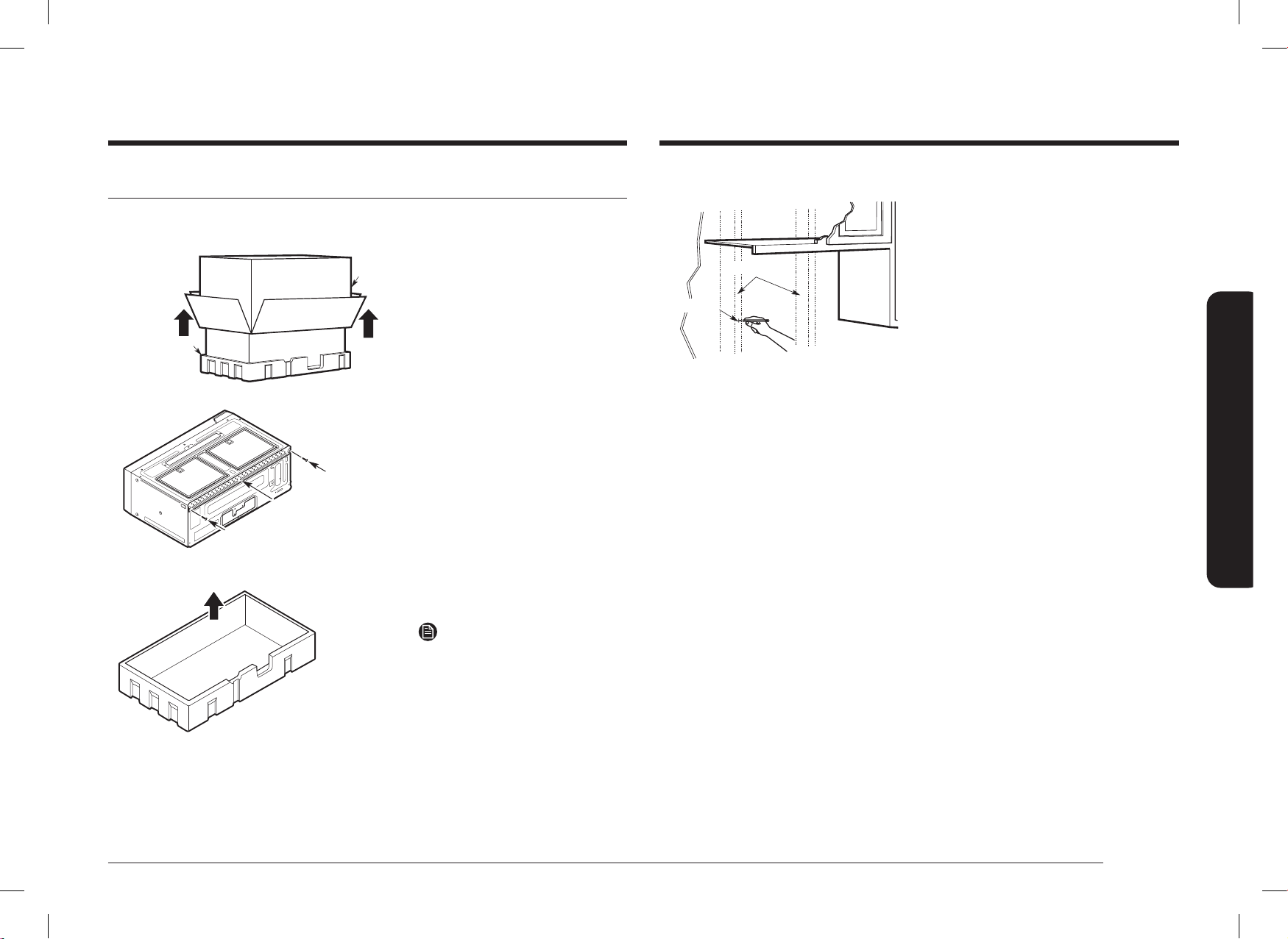
B. Finding the wall studs
Center
Wall Studs
1. Find the studs using one of the following
methods:
A. With a stud nder – a magnetic
device which locates nails.
OR
B. Use a hammer to tap lightly across
the mounting surface until you hear a
solid sound. This will indicate a stud
location.
2. After locating the stud(s), locate the
stud’s center by probing the wall with a
small nail to nd the edges of the stud.
Then, place a mark halfway between the
edges. The center of any adjacent studs
should be 16˝ or 24˝ from this mark.
3. Draw a line down the center of the studs.
THE MICROWAVE MUST BE CONNECTED TO AT LEAST ONE WALL STUD.
Step-by-step installation guide
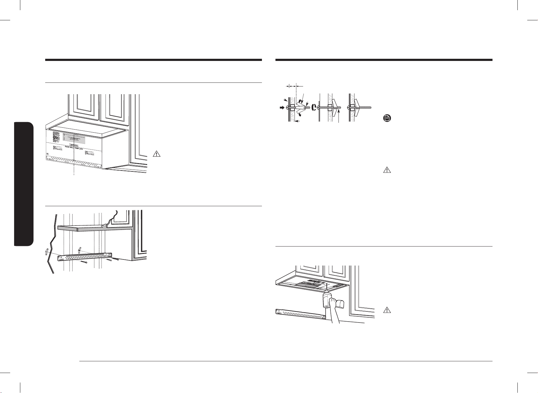
Step 1. Placement of the mounting plate
A. Removing the microwave oven from the carton/Removing the mounting plate
Carton
Styrofoam
Mounting Plate
Screws
Screws
1. Remove the installation
instructions, Exhaust Adaptor,
lters, glass tray, and the small
hardware bag. Do not remove
the Styrofoam protecting the
front of the oven.
2. Fold back all 4 carton aps
fully against carton sides. Then
carefully roll the oven and
carton over onto the top side.
The oven should be resting in
the Styrofoam.
3. Pull the carton up and off the
oven.
4. Remove and properly discard
plastic bags.
5. Remove the 2 screws from
the mounting plate. This plate
will be used as the rear wall
template and for mounting.
NOTE
Retain the two screws. You will
need to re-insert the screws in their
original locations after you have
removed the mounting plate.
DE68-04709D-00_IM_ME11F7510MT_AA_EN.indd 9DE68-04709D-00_IM_ME11F7510MT_AA_EN.indd 9 2024-11-07 오후 3:28:592024-11-07 오후 3:28:59
10 English
Step-by-step installation guide
Step-by-step installation guide
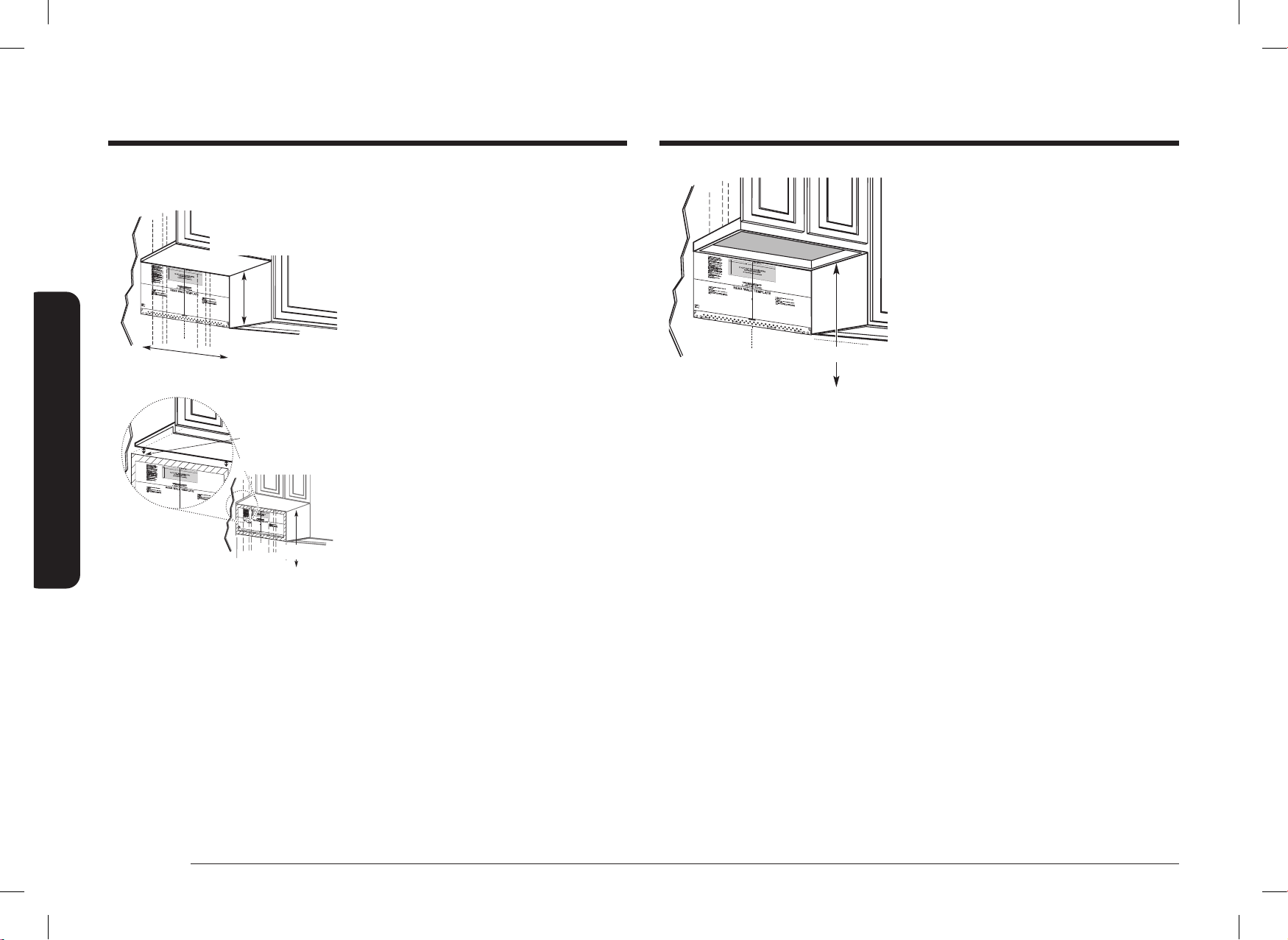
C. Determining wall plate location under your cabinet
C
L
At least 30˝
12˝(30.5cm) minimum
13˝(33.0cm) maximum
upper cabinet and
side cabinet depth
Plate position – beneath a at bottom cabinet.
Draw a vertical line on the wall at the center of
the 30˝ wide space. Tape the Rear Wall Template
onto the wall so that the top of the template
touches the bottom of the cabinet and the
centerline on the template lines up with the line
you drew on the wall.
Plate position – beneath recessed bottom
cabinet with front overhang
C
L
Draw a horizontal
line to mark how far
the inside of the front
overhang descends
below the cabinet.
24
1
/5˝
Plate position – beneath a recessed bottom
cabinet with a front overhang.
Draw a vertical line on the wall at the center of
the 30˝ wide space. Draw a second, horizontal
line on the wall below the cabinet to mark how
far the inside of the front overhang descends
below the cabinet. Tape the Rear Wall Template
onto the wall so that the top of the template
touches the bottom of the horizontal line and
the centerline on the template lines up with the
vertical line.
C
L
24
1
/5˝
Plate position – beneath a framed recessed
cabinet bottom.
Draw a vertical line on the wall at the center of
the 30˝ wide space. Tape the Rear Wall Template
onto the wall so that the top of the template
touches the bottom of the cabinet frame and the
centerline on the template lines up with the line
you drew on the wall.
Your cabinets may have decorative trim that interferes with the microwave installation.
Remove the decorative trim to install the microwave properly and to make it level.
THE MICROWAVE MUST BE LEVEL.
Use a level to make sure the cabinet bottom is level.
DE68-04709D-00_IM_ME11F7510MT_AA_EN.indd 10DE68-04709D-00_IM_ME11F7510MT_AA_EN.indd 10 2024-11-07 오후 3:28:592024-11-07 오후 3:28:59
English 11
Step-by-step installation guide
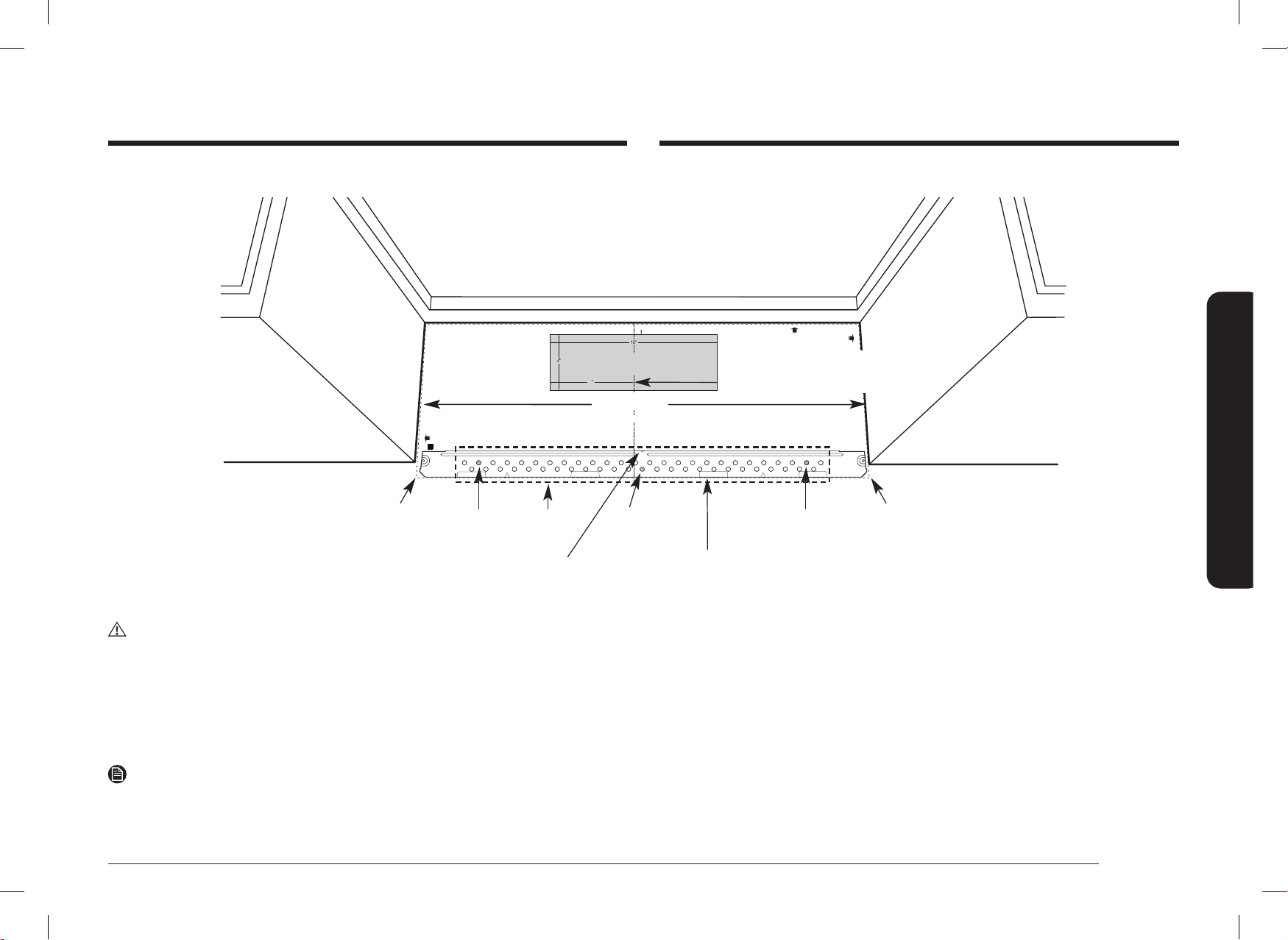
1. Draw a horizontal line on the wall at the bottom of the “Rear Wall Template”.
2. Drill
5
/8˝ holes for toggle bolts in 2 locations (Hole A, Hole B) as shown in the illustration
above. If the location of a hole lines up with a stud, drill a
3
/16˝ hole for a wood screw. You
cannot use a toggle bolt to attach the wall plate to a stud.
NOTE
DO NOT MOUNT THE PLATE AT THIS TIME.
D. Aligning the wall plate
C
L
NOTE: IT IS VERY IMPORTANT TO
READ AND FOLLOW THE DIRECTIONS
IN THE INSTALLATION INSTRUCTIONS
BEFORE PROCEEDING WITH THIS
REAR WALL TEMPLATE.
This Rear Wall Template serves to position the bottom
mounting plate and to locate the horizontal exhaust outlet
1. Use a level to check that the template is positioned accurately.
2. Locate and mark at least one stud on the left or right side of the centerline.
NOTE:
It is important to use at least one wood screw mounted rmly in a stud to support
the weight of the microwave. Mark two additional, evenly spaced locations for
the supplied toggle bolts.
3. Drill holes in the marked locations. Where there is a stud, drill a 3/16” hole for wood screws,
for holes that do not line up with a stud, drill 5/8” holes for toggle bolts
NOTE:
DO NOT INSTALL THE MOUNTING PLATE AT THIS TIME.
4. Remove the template from the rear wall.
5. Review the Installation Instruction book for your installation situation.
Français au verso.
3/8
"
TO EDGE
F. CUT OUT FOR HORIZONTAL
OUTSIDE EXHAUST
CUT HOLE THROUGH REAR WALL FOR EXHAUST ADAPTOR
REAR WALL TEMPLATE
CAUTION - IF EXHAUST ADAPTOR IS POSITIONED OUTSIDE
RECOMMENDED DIMENSION, GREASE-LADEN AIR WILL
DISCHARGE INTO HOUSE STRUCTURE.
Locate and mark holes to align with holes in the mounting plate.
IMPORTANT:
LOCATE AT LEAST ONE STUD ON EITHER SIDE OF THE CENTERLINE.
MARK THE LOCATION FOR 2 ADDITIONAL, EVENLY SPACED TOGGLE
BOLTS IN THE MOUNTING PLATE AREA.
IT IS RECOMMENDED TO INSTALL BOLTS IN A, B, AND C HOLES. THE LOCATION
MAY BE SUBJECT TO CHANGE ACCORDING TO CIRCUMSTANCES BUT IT IS
RECOMMENDABLE TO INSTALL THEM NEAR THE THREE HOLES MENTIONED.
Trim the rear wall template along the dotted line.
Trim the rear wall template along the dotted line.
Locate and mark holes to align with holes in the mounting plate.
IMPORTANT:
LOCATE AT LEAST ONE STUD ON EITHER SIDE OF THE CENTERLINE.
MARK THE LOCATION FOR 2 ADDITIONAL, EVENLY SPACED TOGGLE
BOLTS IN THE MOUNTING PLATE AREA.
IT IS RECOMMENDED TO INSTALL BOLTS IN A, B, AND C HOLES. THE LOCATION
MAY BE SUBJECT TO CHANGE ACCORDING TO CIRCUMSTANCES BUT IT IS
RECOMMENDABLE TO INSTALL THEM NEAR THE THREE HOLES MENTIONED.
Printed in Malaysia
DE68-04707A-00
30
"
MINIMUM WIDTH REQUIRED
Draw a horizontal line on the wall along the bottom
of the “Rear Wall Template”.
Draw a vertical line on the
wall to mark the center of the
cabinet above.
Horizontal Line
Area E
Centerline
notches
Hole A
Hole B
Hole C
Horizontal Line
CAUTION
Wear gloves to avoid cutting ngers on sharp edges.
3. Holes A and B are inside area E. If none of these holes line up with a stud, nd a stud
in area E that lines up with a hole circle in Area E, and then drill a
3
/16˝ hole into it for
a wood screw. You must have at least one wood screw mounted rmly into a stud to
support the weight of the microwave. Set the mounting plate aside.
DE68-04709D-00_IM_ME11F7510MT_AA_EN.indd 11DE68-04709D-00_IM_ME11F7510MT_AA_EN.indd 11 2024-11-07 오후 3:28:592024-11-07 오후 3:28:59
12 English
Step-by-step installation guide
Step-by-step installation guide
Step 2. Ventilation types (choose A, B or C)
This microwave oven is compatible with the following three types of ventilation:
A. Outside top exhaust
(vertical duct)
B. Recirculating
(non-vented ductless)
Bracket
C. Outside back exhaust
(horizontal duct)
NOTE
This microwave is shipped assembled for Recirculating. An Exhaust Adaptor is shipped
assembled and attached to the ller-upper. Select the type of ventilation required for your
installation and proceed to that section.
A. Outside top exhaust (vertical duct)
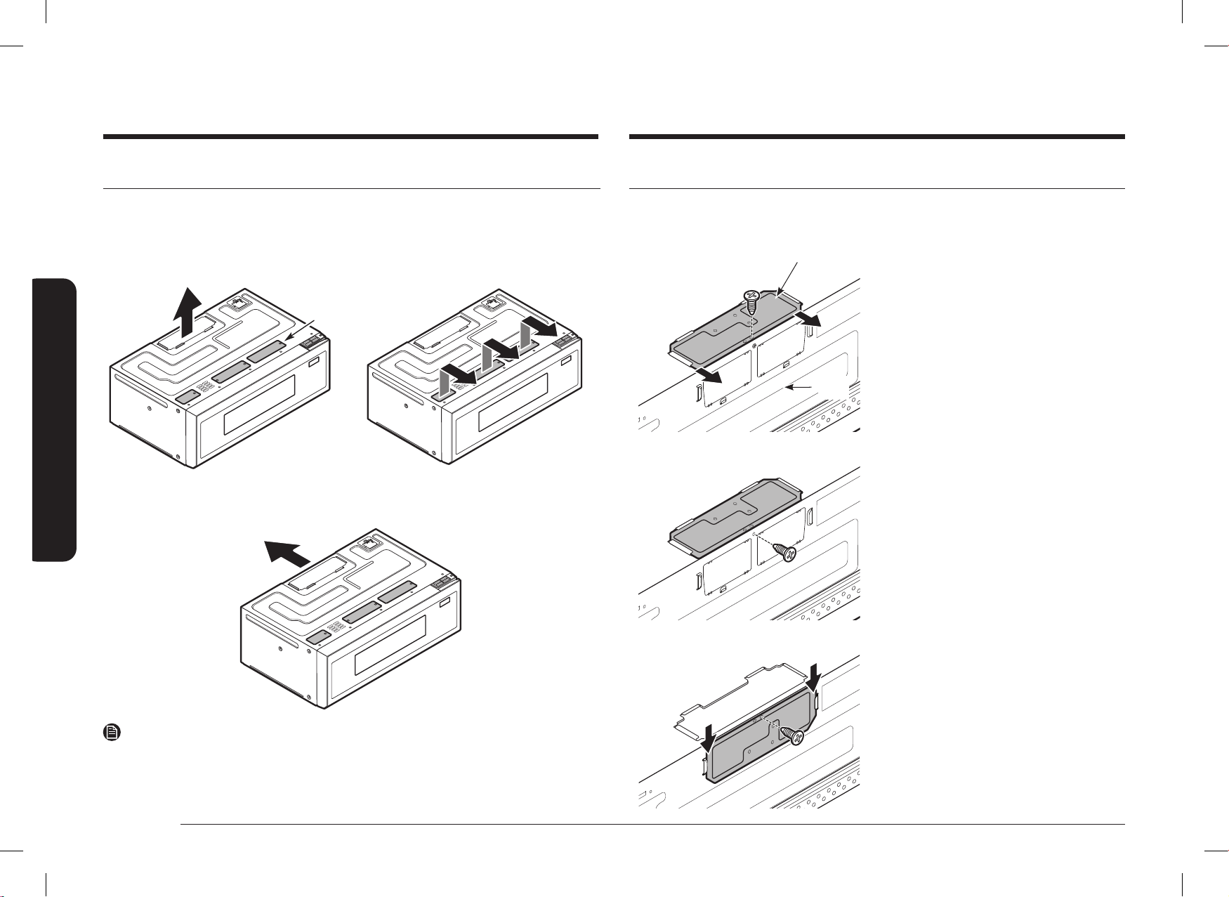
A1. ADAPTING THE COVER PANEL FOR THE EXHAUST ADAPTOR
Cover
Panel
Back
Panel
1. Remove 1 screw from Cover Panel and
take off Cover Panel.
2. Remove 1 screw from Back Panel.
3. Assemble the Cover Panel as sliding from
top to bottom and the screw that was
removed from Back Panel.
DE68-04709D-00_IM_ME11F7510MT_AA_EN.indd 12DE68-04709D-00_IM_ME11F7510MT_AA_EN.indd 12 2024-11-07 오후 3:28:592024-11-07 오후 3:28:59
English 13
Step-by-step installation guide
Bracket
The marked Brackets should not have
Vent holes.
NOTE
You must check bracket picture according to
ventilation type at page 12.
NOTE
Apply A1 and A2 equally.
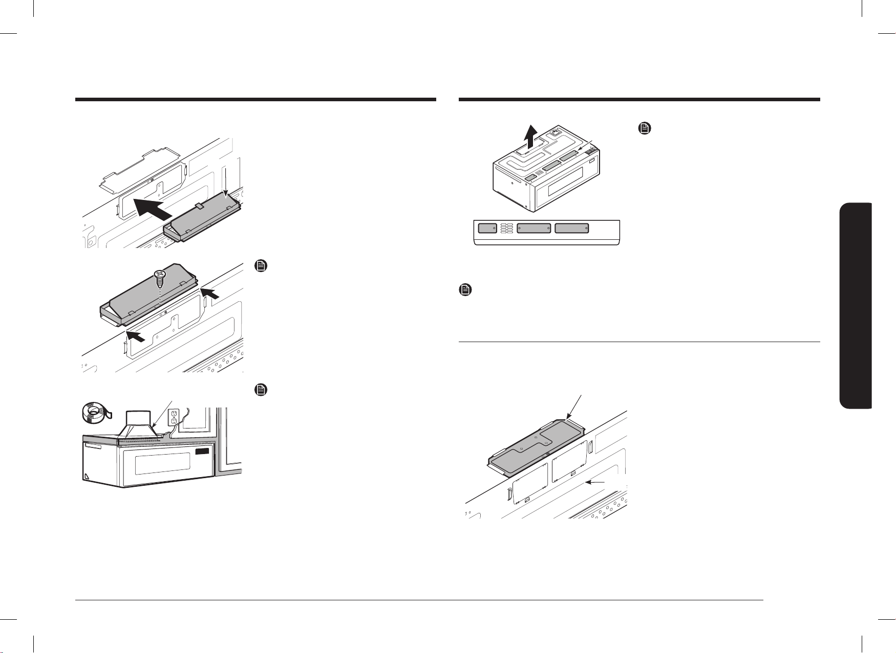
B. Recirculating (non-vented ductless)
B1. Adapting the COVER PANEL for recirculation
Cover
Panel
Back
Panel
1. Make sure the Cover Panel is assembled
properly. (Top assembly)
A2. INSTALLATION DAMPER
Damper
1. Remove the tape securing the Damper.
2. Assemble the Damper as sliding from
back to front until stopped.
NOTE
Make sure Dampers swing freely.
House Duct
House Duct
NOTE
• You must attach the House Duct to the
Exhaust Adaptor after installation is
complete.
• You must seal Exhaust Duct joints using
Duct Tape.
DE68-04709D-00_IM_ME11F7510MT_AA_EN.indd 13DE68-04709D-00_IM_ME11F7510MT_AA_EN.indd 13 2024-11-07 오후 3:29:002024-11-07 오후 3:29:00
14 English
Step-by-step installation guide
Step-by-step installation guide
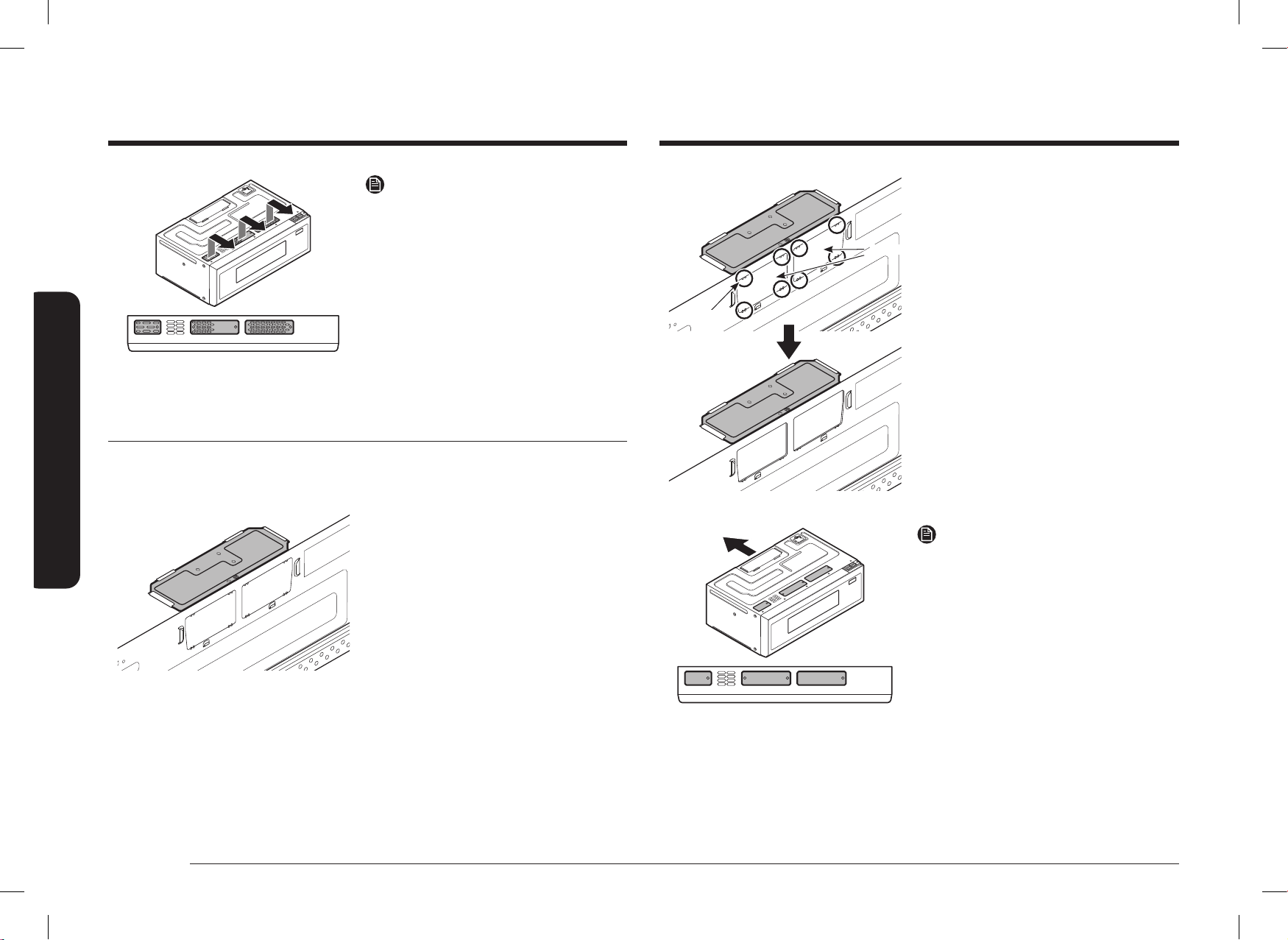
Plate
8EA
After removing Plates
2. Cut 8 area to remove plates using nipper.
The marked Brackets should not have
Vent holes.
NOTE
You must check bracket picture according to
ventilation type at page 12.
The marked Brackets should have Vent
holes.
NOTE
• The Exhaust Adaptor with the Damper
is not needed for recirculating type. You
may want to save them for possible future
use.
• You must check bracket picture according
to ventilation type at page 12.
C. Outside back exhaust (horizontal duct)
C1. Adapting the COVER PANEL for outside back exhaust
1. Make sure the Cover Panel is assembled
properly. (Top assembly)
DE68-04709D-00_IM_ME11F7510MT_AA_EN.indd 14DE68-04709D-00_IM_ME11F7510MT_AA_EN.indd 14 2024-11-07 오후 3:29:002024-11-07 오후 3:29:00
English 15
Step-by-step installation guide
Dim. Comparison
13
9
1
4
1
2
1
2
5
3
4
6
1
2
6
1
4
13
3
32
(332.4mm)
9
1
4
(235mm)
13
3
32
(332.4mm)
9
1
4
(235mm)
1
1
2
1
15
32
(37.3mm)
3
4
4
3
4
4
6
31
64
(164.5mm)
CUT OUT SLOT
FOR SMOOTH
FLAT BOTTOM
CABINETS ONLY
POWER
CORD
CUT OUT SLOT
FOR SMOOTH
FLAT BOTTOM
CABINETS ONLY
Screw exposure length
(Cabinet bottom to End of bolt)
without the Supporter.
28
32
1
26
32
~
(46mm) (22mm)
Screw exposure length
(Cabinet bottom to End of bolt)
when using the Supporter.
28
32
1
30
32
~
(49mm) (22mm)
NOTE
After assembling the screws in the D and E holes,
check the dimensions.
11
7
16
(290.75mm)
6
31
64
(164.5mm)
DE68-04708A-00
3
1
/2˝
(88.7mm)
1
27
/32˝
(47mm)
9
1
/4˝
(235mm)
1
15
/32˝
(37.3mm)
26
3
/16˝
(664.8mm)
1
27
/32˝
(47mm)
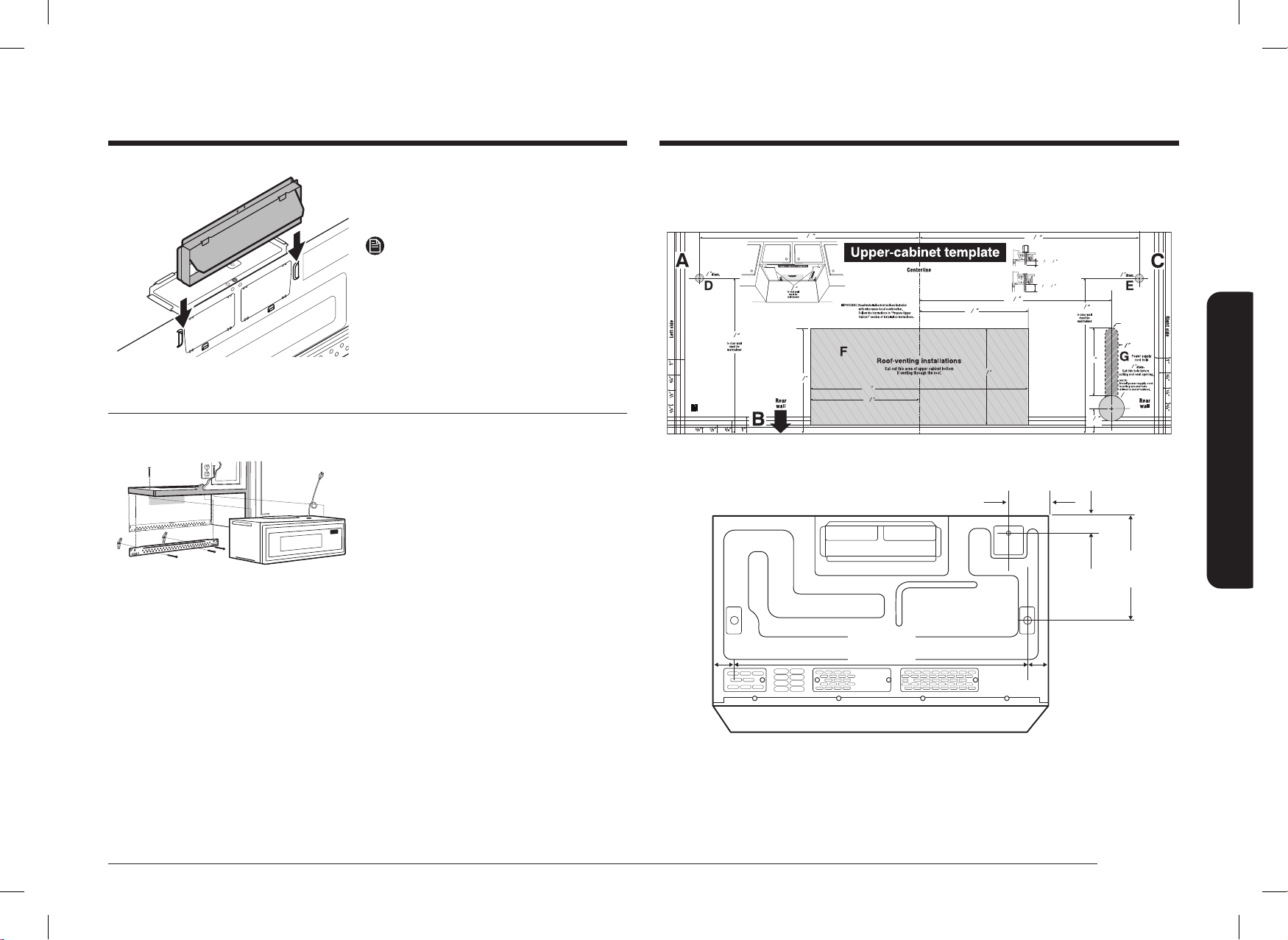
3. Remove the tape securing the Damper.
4. Assemble the Damper as sliding from top
to bottom until stopped.
NOTE
Make sure Dampers swing freely.
Step 3. Installation
INSTALLATION OVERVIEW
F. CUT OUT FOR HORIZONTAL
OUTSIDE EXHAUSE
REAR WALL TEMPLATE
A. Prepare the Rear Wall (for outside back
exhaust/horizontal duct only).
B. Attach the Mounting Plate to the Wall.
C. Prepare the Cabinet above.
D. Mount the Microwave Oven.
E. Connect the Ductwork (for outside top
exhaust/vertical duct only).
DE68-04709D-00_IM_ME11F7510MT_AA_EN.indd 15DE68-04709D-00_IM_ME11F7510MT_AA_EN.indd 15 2024-11-07 오후 3:29:002024-11-07 오후 3:29:00
16 English
Step-by-step installation guide
Step-by-step installation guide
Bolt End
Mounting
Plate
Toggle
Bolt
Wall
Toggle Wings
3. Place the mounting plate against the
wall, pinch the wings of each toggle
together, and then insert the toggle wings
of each toggle into and through the holes
in the wall.
NOTE
Before tightening the toggle bolts and wood
screw, make sure the bottom of the Mounting
plate runs along the bottom Horizontal line
of the “Rear wall Template” and the Mounting
plate is properly centered under the cabinet.
CAUTION
Be careful to avoid pinching your ngers
between the back of the mounting plate and
the wall.
4. Tighten all bolts. Pull the plate away from
the wall to help tighten the bolts. Tighten
the screw.
C. Use the top cabinet template to prepare the cabinet above
You need to drill holes for the top support screws and a hole large enough for the power cord
to t through.
• Read the instructions on the TOP CABINET
TEMPLATE.
• Tape it underneath the top cabinet.
• Drill the holes, following the instructions
on the TOP CABINET TEMPLATE.
CAUTION
Wear safety goggles when drilling holes in the
cabinet bottom.
A. Prepare the rear wall for outside back exhaust
You need to cut an opening in the rear wall for outside exhaust.
C
L
• Read the instructions for outside back
exhaust on the REAR WALL TEMPLATE.
• Tape the REAR WALL TEMPLATE to the
rear wall.
• Cut the opening, following the
instructions on the REAR WALL
TEMPLATE.
CAUTION
Do not cut an opening in the rear wall if you are
installing the microwave with vertical duct or
non-vented ductless ventilation.
B. Attach the mounting plate to the wall
Attach the plate to the wall using toggle bolts.
At least one wood screw must be used to
attach the plate to a wall stud.
1. Remove the toggle wings from the bolts.
2. Insert the bolts into the mounting plate
through the holes designated to go into
drywall, and then reattach the toggle
wings so that ¾˝ of the bolt protrudes
beyond the wing.
DE68-04709D-00_IM_ME11F7510MT_AA_EN.indd 16DE68-04709D-00_IM_ME11F7510MT_AA_EN.indd 16 2024-11-07 오후 3:29:002024-11-07 오후 3:29:00
English 17
Step-by-step installation guide
Equivalent
to Depth
of Cabinet
Recess
Cabinet Bottom Shelf
Microwave Oven Top
Cabinet Front
Filler Block
Self-Aligning
Screw
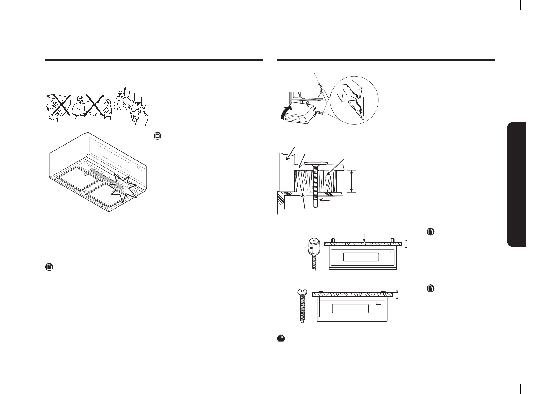
1. Lift the microwave, tilt it forward, and
hook the slots at the back bottom edge
onto the four lower tabs of the mounting
plate.
2. Rotate the front of the oven up against
the cabinet bottom.
3. Insert a self-aligning screw through the
top center cabinet hole. Temporarily
secure the oven by turning the screw at
least two full turns after the threads have
engaged. (It will be completely tightened
later.) Be sure to keep the power cord
tight. Be careful not to pinch the cord,
especially when mounting ush to the
bottom of cabinet.
Thickness of cabinet
¹/16~
15
/16”
1
/16 ~
15
/16 ˝
Supporter
NOTE
If Cabinet Thickness is Under
1 ˝, Use Supporter.
1
~
2”
1~2˝
NOTE
If Cabinet Thickness is over
1 ˝, Remove Supporter from
the Self-Aligning Screw.
NOTE
The self-aligning screw can be installed up to 1
15
/16 ˝ (49mm).
D. Mount the microwave oven
FOR EASIER INSTALLATION AND PERSONAL
SAFETY, WE RECOMMEND THAT TWO PEOPLE
INSTALL THIS MICROWAVE OVEN.
IMPORTANT: Do not grip or use the handle
during installation.
NOTE
• If your cabinet is metal, use the nylon
grommet in the power cord hole to
prevent the cord from being cut.
• Filler blocks are required when mounting
this unit under any cabinet with a
recessed bottom or front overhang. (See
page 10.)
IMPORTANT: The case damage that will occur
from over tightening screws if
you do not use ller blocks is not
covered under warranty.
IMPORTANT: Be careful not to damage
the lower Lamp Glass during
handling.
NOTE
When mounting the microwave oven, thread the power cord through hole in the bottom of
the top cabinet. Keep it tight throughout Steps 1–3. Do not pinch the cord or lift the oven by
pulling cord.
DE68-04709D-00_IM_ME11F7510MT_AA_EN.indd 17DE68-04709D-00_IM_ME11F7510MT_AA_EN.indd 17 2024-11-07 오후 3:29:002024-11-07 오후 3:29:00
18 English
Step-by-step installation guide
Step-by-step installation guideStep-by-step installation guide
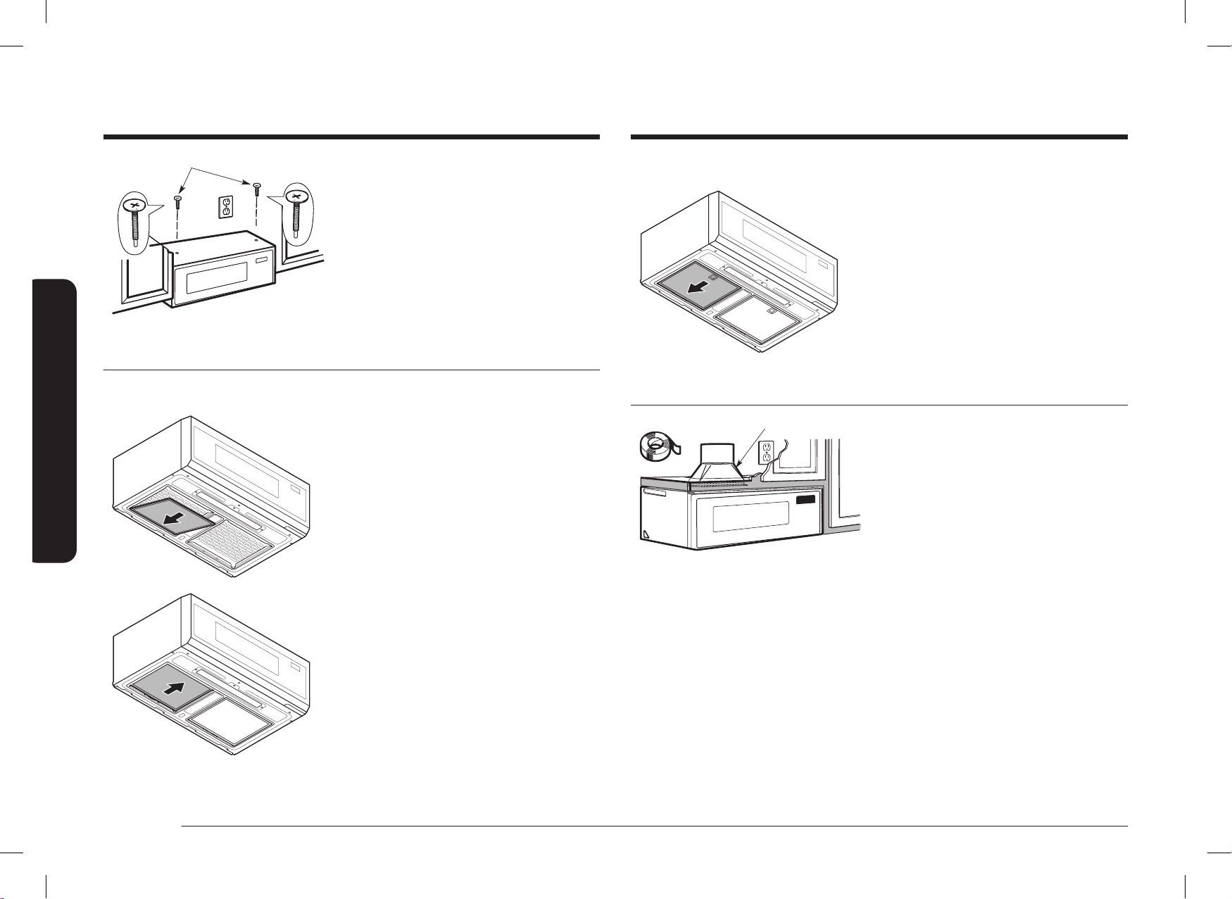
E2. Grease Filter assembly method
1. Push the Grease Filter backward and
insert the Grease Filter until atness with
bottom surface of products.
F. Connect the ductwork for outside top exhaust
House Duct
House Duct
1. Extend the House Duct down to connect
to the Exhaust Adaptor.
2. Seal the exhaust duct joints using duct
tape.
4. Attach the microwave oven to the top
cabinet.
5. Insert the 2 self-aligning screws through
the cabinet bottom shelf and ller block
into the outer top cabinet of the unit.
Continue to support the unit until both
screws are inserted and engaged at
least two full turns, then fully tighten all
screws until the unit is secure.
E. Installing the charcoal lters and Grease Filters
E1. Charcoal Filter assembly method
1. Insert the Charcoal Filter from the back.
2. Raise the front of the Charcoal Filter until
it is at with the bottom, and then pull it
forward to lock it in place.
DE68-04709D-00_IM_ME11F7510MT_AA_EN.indd 18DE68-04709D-00_IM_ME11F7510MT_AA_EN.indd 18 2024-11-07 오후 3:29:012024-11-07 오후 3:29:01
English 19
Step-by-step installation guide
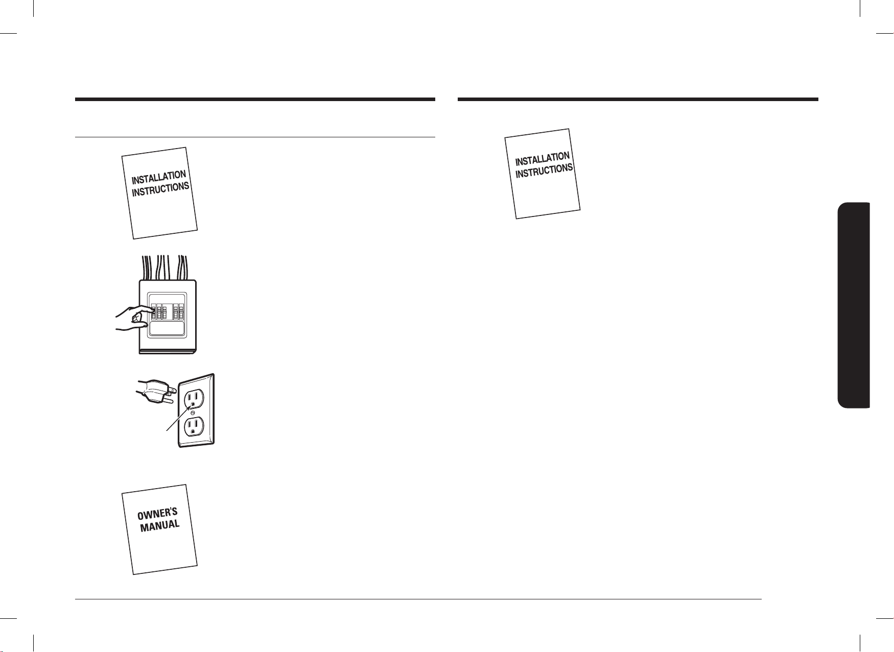
7. Keep installation instructions for the local
inspector’s use.
Step 4. Before you use your microwave
1. Make sure the microwave oven has been
installed according to instructions.
2. Remove all packing material from the
microwave oven.
3. Install the turntable and ring in the cavity.
4. Replace the house fuse or turn the breaker
back on.
Insure proper
ground exists
before use.
5. Plug the power cord into a dedicated 15
amp electrical outlet.
6. Read the Owner’s Manual.
DE68-04709D-00_IM_ME11F7510MT_AA_EN.indd 19DE68-04709D-00_IM_ME11F7510MT_AA_EN.indd 19 2024-11-07 오후 3:29:012024-11-07 오후 3:29:01
Please be advised that the Samsung warranty does NOT cover service calls to explain product operation, correct improper installation, or perform normal cleaning or maintenance.
QUESTIONS OR COMMENTS?
COUNTRY CALL OR VISIT US ONLINE AT
U.S.A
Consumer Electronics
1-800-SAMSUNG (726-7864) www.samsung.com/us/support
CANADA 1-800-SAMSUNG (726-7864)
www.samsung.com/ca/support (English)
www.samsung.com/ca_fr/support (French)
DE68-04709D-00
Scan the QR code* or visit
www.samsung.com/spsn
to view our helpful
How-to Videos and Live Shows
* Requires reader to be installed on your
smartphone
DE68-04709D-00_IM_ME11F7510MT_AA_EN.indd 20DE68-04709D-00_IM_ME11F7510MT_AA_EN.indd 20 2024-11-07 오후 3:29:012024-11-07 오후 3:29:01