
SURETRACE
™
CIRCUIT TRACER
Your IDEAL troubleshooting solution. Designed
to find everything, while saving you time and money.
• Finds:
– Breakers and Fuses
– Splice Errors
– Dead Shorts
– Energized/De-Energized Conductors in Walls, Ceilings and Floors
• Works on 3-Phase Systems
• Indicates Voltage Level (61-948)
• Tests for Continuity (61-948)
Scan here for more
details and
informational videos

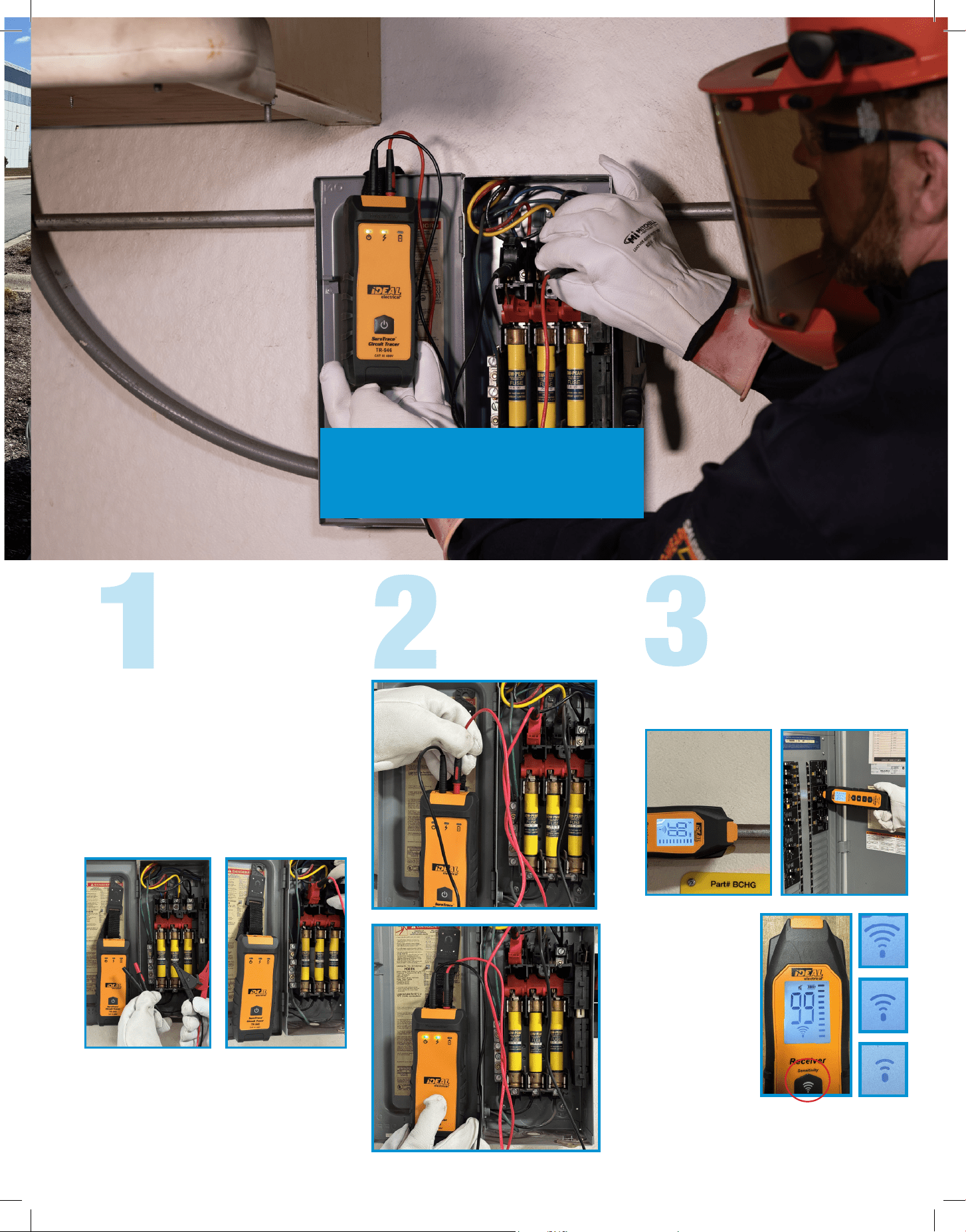
FINDING ENERGIZED
BREAKERS AND FUSES
Hold the Receiver near the Transmitter to
verify connection, confirmed by the
lightning bolt symbol.
Place Receiver flat
on the front near the
top of each panel
until the highest
reading is reached.
This is the correct
panel.
TIPS FOR HIGHEST
ACCURACY:
• Perform two slow scans around
breakers to start.
• Hold Receiver at a right angle to the
breaker and level with the floor.
• Once highest reading is found, tilt
Receiver up and down at a 45° angle
to confirm consistent high numeric
reading.
Plug Transmitter
into an outlet and
power on.
Set Receiver to the highest
sensitivity mode (Receiver
defaults to this).
Set Receiver to the lowest
sensitivity mode (also known
as Breaker mode).
Scan each breaker and look for the highest
reading. This is the correct breaker.
Turn breaker off and verify CertainCircuit™
Lightning bolt indication has gone out.
If two panels read
99 or are close in
values, press the
sensitivity button
once to reduce the
receiver sensitivity
one level and rescan.
STEP 1: VERIFY POWER
AND SIGNAL ON CIRCUIT
STEP 2: SCAN EACH
PANEL FOR THE HIGHEST
READING
STEP 3: SCAN EACH
BREAKER FOR HIGHEST
READING
BREAKER OR FUSE
FIND IT
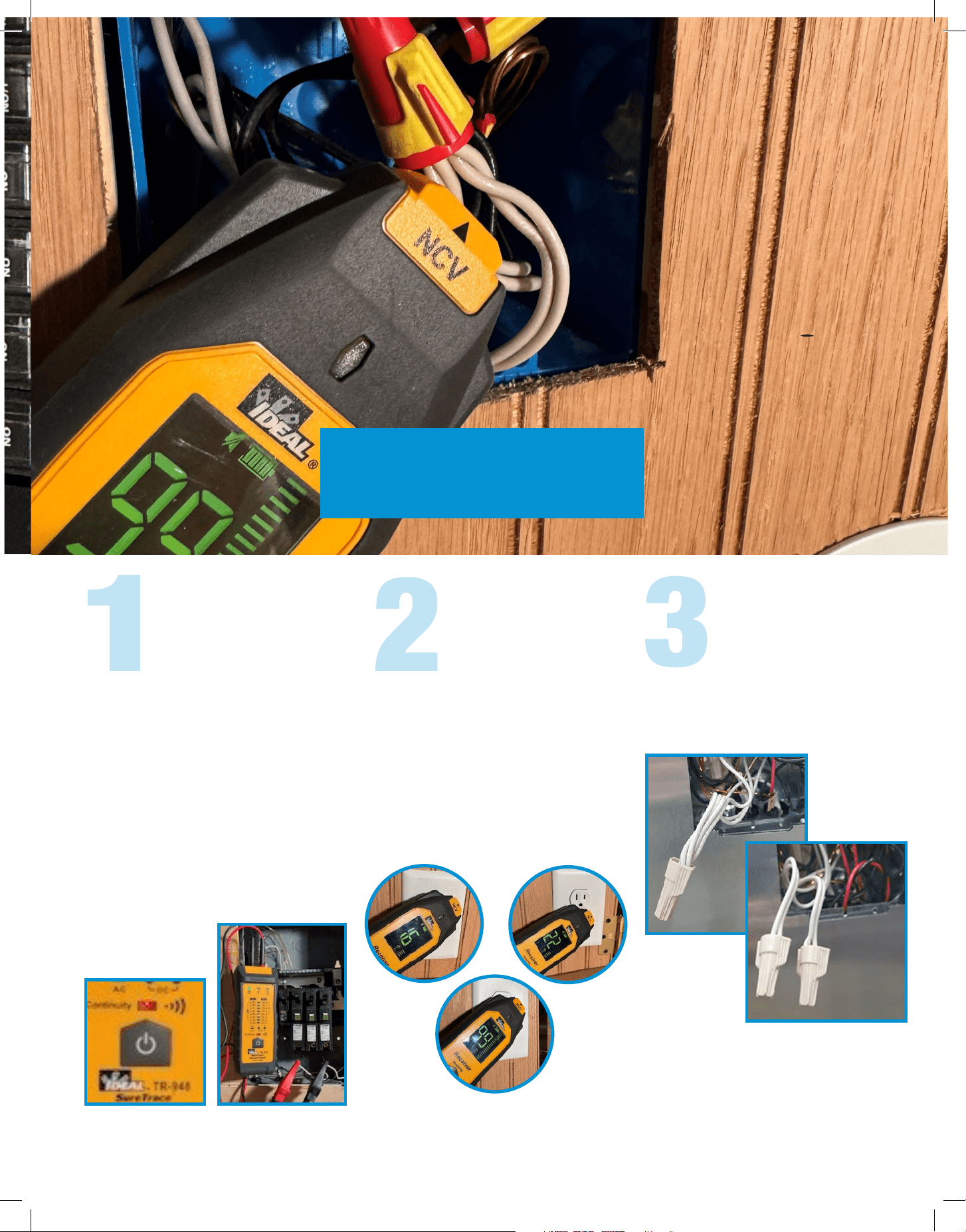
Identify the incorrect splice, separate each
circuit’s neutral conductors, and re-splice
each neutral circuit’s connections.
STEP 1: ATTACH CLIPS
STEP 2: SCAN STEP 3: SEPARATE
NEUTRALS
Scan each electrical location (switch,
outlet, light fixture, etc.) with the Receiver
in the 3rd sensitivity mode setting until
you identify the highest numeric reading
on the Receiver.
The highest numerical value on the
Receiver indicates the likely location of
the incorrectly spliced conductors.
COMMON SPLICE ERROR
1. Confirm branch circuits are
de-energized
2. Use a continuity check to determine
which conductors are affected
3. Attach Transmitter alligator clips to the
affected breaker neutrals.(The two
neutrals of the AFCI/GFCI/Combo
Breakers that are nuisance tripping)
Note: The 61-948 will indicate continuity
automatically, the 61-946 requires a
separate tester.
For informational videos please go to IDEALCircuit-Tracer.com
FIND IT
FOR A NEUTRAL TO GROUND
CONDITION WITH AFCI/GFCI/
COMBO BREAKERS
FOR STANDARD BREAKERS
Attach alligator
clips to the
breaker’s neutral
wire and ground
wire.
Attach alligator
clips to the neutral/
ground bar and
breaker’s hot wire.
STEP 1: DETERMINE THE
SHORTED CONDITION
STEP 3: SCAN
STEP 2: ATTACH CLIPS
AND SET RECEIVER’S
SENSITIVITY
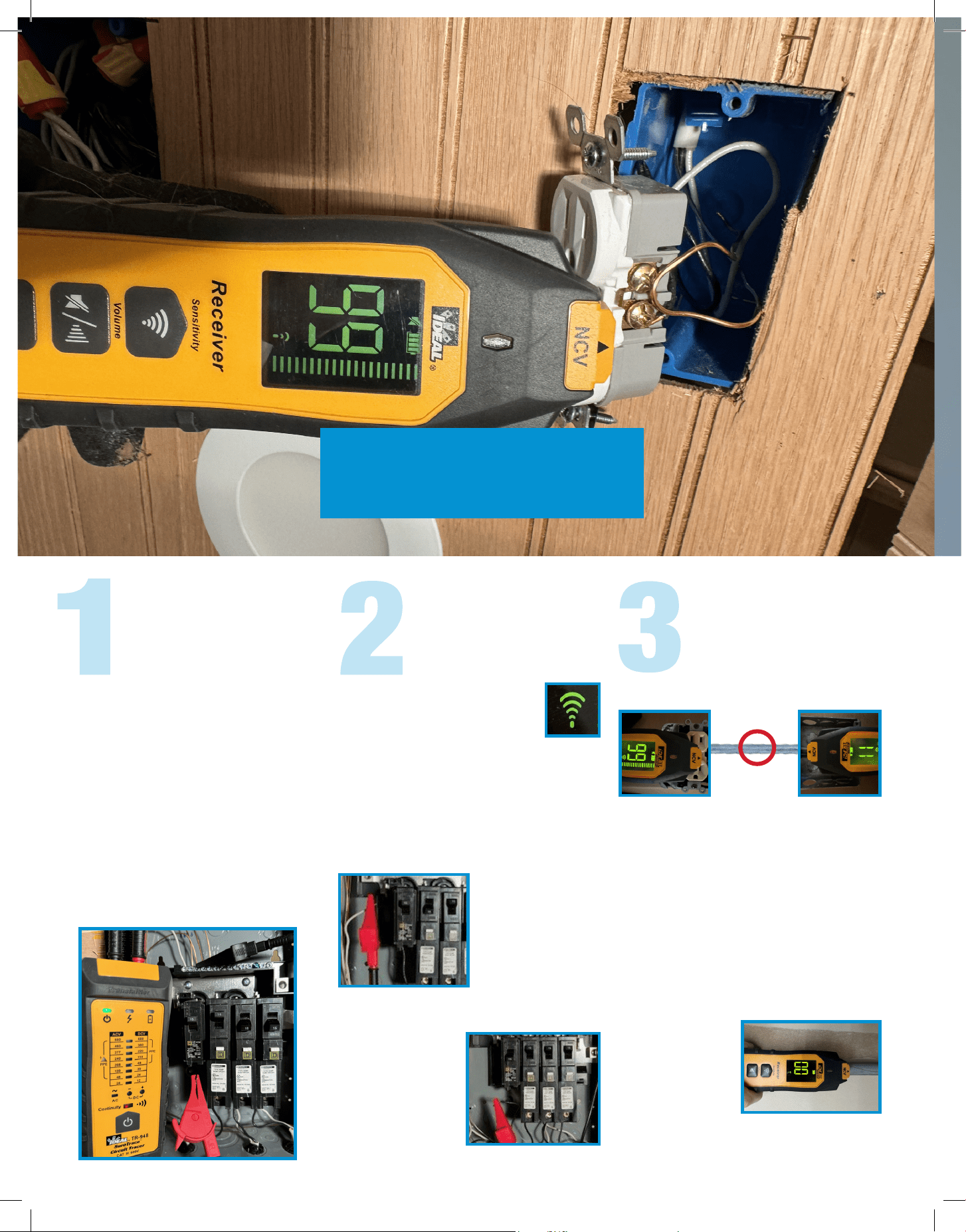
1. Confirm branch circuit is
de-energized.
2. Unplug all items connected to the
affected branch circuit.
3. Verify the fault is in the affected
branch circuit.
4. Use a continuity check to determine
which conductors are affected.
Note: The 61-948 will indicate continuity
automatically, the 61-946 requires a
separate tester.
Set Receiver to the first, or
highest, sensitivity mode.
Note: Sensitivity levels may need to be
adjusted in various situations
METAL CONDUIT
DEAD SHORT FOUND IN
CONNECTING
CONDUIT
Since metal conduit cannot be traced
through, simply trace over the outlets in a
circuit. The outlet where the reading starts
to drop means that the short is between
that outlet and the previously traced outlet.
PVC CONDUIT/UNDERGROUND
Hold the Receiver
flat on the conduit/
ground and trace
along until the
reading drops to
zero. This is the location of the short.
DEAD SHORT
FIND IT

Plug the transmitter
into a wall outlet using
the outlet plug adapter
provided with the
circuit tracer.
Hold the receiver near the transmitter to
verify signal strength. The lightning bolt
indicates power is present on the circuit.
Set the receiver to the highest
sensitivity mode.
Start several feet away from the transmitter,
then scan the area while holding the back
of the receiver flat.
Rotate the receiver to find the highest
numerical reading. This is necessary
to follow signal strength variations while
tracing due to bends, twists and conduc-
tors that run deeper or shallower along
their path. Signal strength variations occur
and may require constant adjustment to
the angle of the receiver to trace.
Adjust the signal strength on the receiver
if needed. If the reading is too high, reduce
the strength. If the reading is too weak,
utilize the remote return path method for
the transmitter, then repeat step 2.
To assist in tracing,
use a small piece of
tape to pinpoint the
location of the cable.
Continue tracing while following the
highest reading until the end of the cable
is found.
Hold the Receiver
flat on the conduit/
ground and trace
along until the
reading drops to
zero. This is the location of the short.
STEP 1: PLUG ADAPTER
INTO CIRCUIT
STEP 2: SET RECEIVER
TO HIGHEST SENSITIVITY
MODE AND SCAN
STEP 3: MAINTAIN
ORIENTATION AND
TRACE
WIRE IN WALL, CEILING AND FLOOR
FIND IT

STEP 1: ATTACH
ALLIGATOR CLIPS
STEP 2: PLUG LEADS
INTO TRANSMITTER AND
TURN IT ON
STEP 3: TURN ON
RECEIVER AND TRACE
Using appropriate
safety methods,
attach the alligator
clips with 3 ft. leads
to the Hot and
Neutral conductors
on the supply side
of the branch
circuit.
Begin tracing the wires
buried in the ground by
following the strongest
signal, and adjusting the
sensitivity to obtain
readings in the
60’s to 80’s.
The orientation of the receiver to the wiring
affects the displayed signal strength.
Simply adjust the orientation of the
Receiver relative to the buried conductor to
maximize the displayed signal strength.
Use appropriate methods and LO/TO to
ensure the conductors are de-energized
and locked out before proceeding.
Verify that you de-energized the correct
conductors before proceeding when
possible. Re-energize after the transmitter
is attached.
Note: The strongest tracing signal will
always be accomplished by connecting
to a closed loop energized circuit with an
active load.
Note: The circuit in these pictures has been de-energized and locked out in accordance with NFPA 70E.
BURIED CONDUCTOR
FIND IT
STEP 1: ATTACHING
ALLIGATOR CLIPS TO
LIVE 3-PHASE SYSTEMS
STEP 2: PLUG LEADS
INTO TRANSMITTER AND
TURN IT ON
STEP 3: TURN ON
RECEIVER AND TRACE
Trace conductors or identify breakers or fuses
by using previously described methods.
Adjust sensitivity
as required to
optimize received
signal strength.
Proper orientation
of the receiver is
important and may
require adjustment
to maximize
displayed signal
strength.
Using appropriate safety methods, attach
the alligator clips with 3 ft. leads to any
two of the three phases. (ensure leads are
not plugged into the transmitter)
Next, plug opposite ends of leads into the
transmitter starting with the black lead
first.
Next, Turn on Transmitter
Note: The circuit in these pictures has been de-energized and locked out in accordance with NFPA 70E.
3-PHASE BREAKER, FUSE, CONDUCTOR
FIND IT
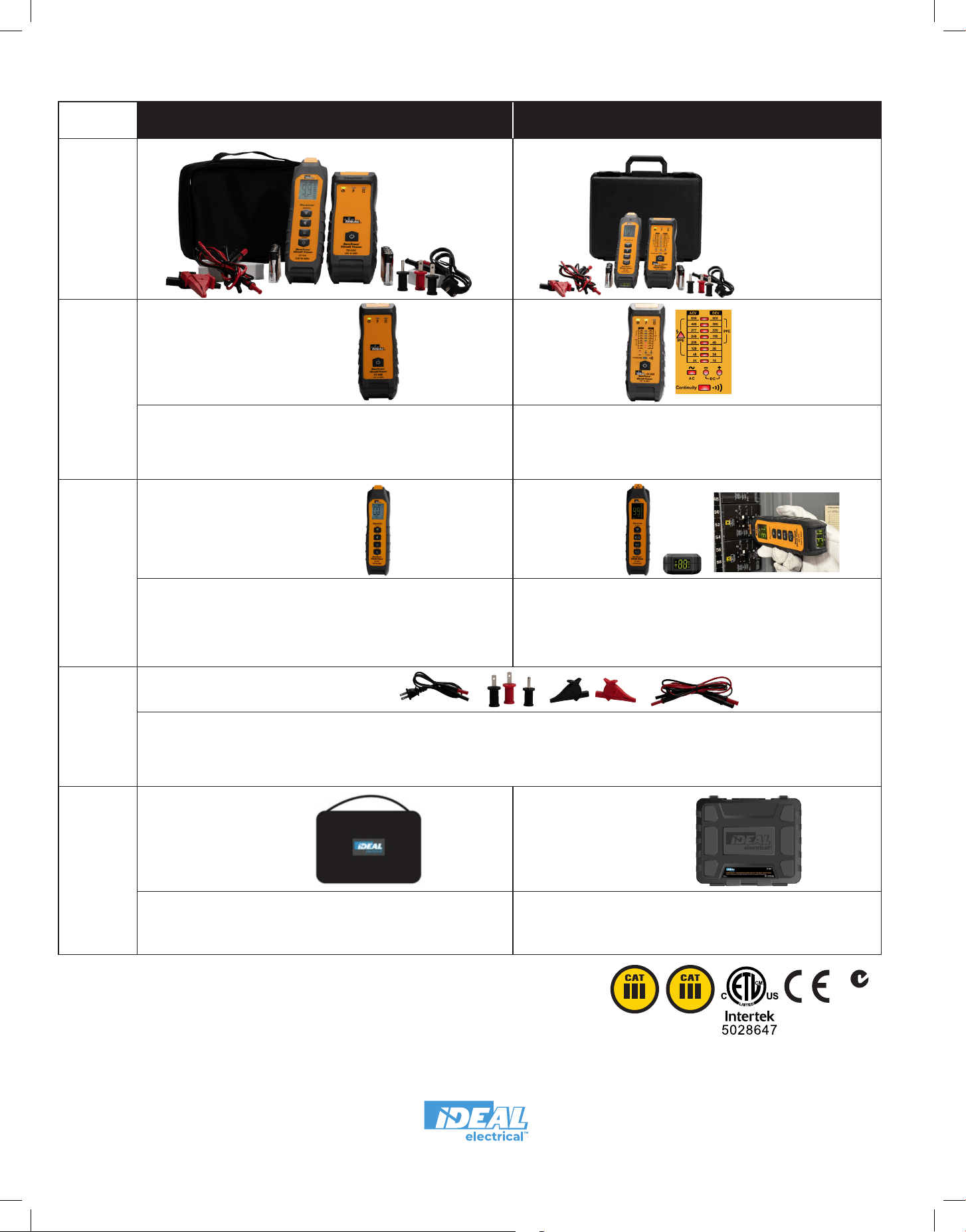
61-946
SureTrace™ Circuit Tracer 0-480V AC/DC
61-948
SureTrace™ Plus Circuit Tracer 0-600V AC/DC
Transmitter*
• CAT III 480V, Range 0-480V AC/DC
• Indicators: Power, Energized Circuit, CertainCircuit™, Battery Level
• Kickstand
• Magnetic Hanging Strap Clip (sold separately, UMHS-757)
• CAT III 600V, Range 0-600V AC/DC
• Indicators: AC/DC Voltage and DC Polarity, Power, Energized Circuit, Battery Level
• Voltage Level Indicator and Continuity Test
• Kickstand
• Magnetic Hanging Strap Clip (sold separately, UMHS-757)
Receiver
• Single LED Screen with Backlight
• Displays: Signal Strength,Sensitivity Level, Energized Circuit, CertainCircuit™,
Peak Signal Strength and Battery Level
• Functions: Sensitivity Setting, Mute, Backlight, On/Off
• Dual High Visibility Displays, Patented 180° Main and TightSight
®
Secondary
Displays
• Displays: Signal Strength, Sensitivity Level, Energized Circuit, Peak Signal, EF
and NCV (when in NCV Mode) and Battery Level
• Functions: Sensitivity Setting, Mute, NCV, On/Off
• Flashlight for use in Poor Lighting Conditions
Leads/
Accessories
• (1) Outlet Plug Adapter (Hot and Neutral only)
• (2) Blade Prongs, Hot and Neutral (one pair)
• (1) Ground Prong
• (2) Alligator Clips
• (2) 3’ Lead Adapters
Case
• Padded Nylon Pouch w/Handle
• Transmitter & Receiver Retained by Straps
• Side Panel Pockets for Battery Storage
• Large Pocket for Lead/ Accessory Storage
• Molded Hard Case with handle and Metal Clips
• Slots for Transmitter, Receiver and Clamp
• Side Slot for Battery Storage
• Large Slots Lead/Accessory Storage
SURETRACE™ KIT OPTIONS
IMPORTANT: This tracer is intended for use by qualified electricians. Follow NFPA 70E Standard for Electrical Safety
in the Workplace when using this tester. Always consult the instruction manual provided with the tester for operational
limitations and procedures associated with a specific tester.
*The transmitter is to be used only on DC, or 50 or 60 Hz AC energized lines.
Output from VFD’s, shipboard voltage inverters or dimmers will damage the unit.
TR-946
TR-948
RC-946
TL-956
C-946 C-950
Residential
Commercial
Commercial
Industrial
Form No. P-5516
©2024 IDEAL INDUSTRIES, INC.
4/24
Printed in U.S.A.
IDEAL Electrical™
1800 S. Prairie Drive, Sycamore, IL 60178, USA / 815-895-5181 • 800-435-0705 in USA
480V 600V
N12966
RC-948
Voltage Level Indicator
Continuity Test