24702
EN
Original Instructions
Version 1
April 2024
6 - 42V DC
CIRCUIT TRACER
AND DETECTOR

User Manual for: Circuit Tracer And Detector
Stock No: 24702
Part No: ETCT
Read this manual in full before using this product and
retain it for future use. Always use the latest version of
the manual.
Please visit drapertools.com/manuals for the
latest version.
1.
– 2 –
EN
2. Product Introduction
2.1 Intended Use
This product is designed to quickly & eortlessly detects
short & open circuits without damaging the wire insulation.
Equipped with a sensitivity controller & exible probe for
restricted areas. Suitable for automotive fault nding &
repairs on direct currents.
Any other application beyond the conditions established
for use will be considered misuse. Draper Tools accepts no
responsibility for improper use of this product.
This product is suitable for use by enthusiasts and
tradespersons alike.
2.2 Specication
Stock No. 24702
Part No. ETCT
Voltage Range: 6 - 42V DC
Power Supply: 2 x PP3 9V (batteries not supplied)
Net Weight: 186g
Detector Dimensions (L X W X H): 192 X 51 X 34mm
Sender Dimensions (L X W X H): 69 X 63 X 28mm
Flexible Probe Length: 172mm
Flexible Probe Diameter: 5mm
Positive Lead Length: 90mm
Negative Lead Length: 90mm
3. Health and Safety Information
– 3 –
EN
4. Symbols
Important: Read all the Health and Safety instructions before attempting to operate, maintain or repair this product.
Failure to follow these instructions may result in injury or damage to the user, the product or the workpiece.
• ALWAYS follow the instructions and procedures listed
in the vehicle’s service manual before using this
device.
• Exceeding the limits listed in this manual may cause
physical injury or permanent damage to the device,
part and circuits being tested.
• Only for testing DC voltage. NEVER connect to
circuits exceeding DC 42 voltage.
• DO NOT use on AC voltage.
• DO NOT apply to any circuits which directly or
indirectly connect to AC lines or other AC power
sources.
• DO NOT use on ignition system components or
circuits.
• Before using this device check the vehicle’s wiring.
Disconnect any part of the system such as air bags,
electronic control modules etc, which are sensitive to
voltage or current pulses.
• After checking the vehicle, ensure that all the
disconnected connections are correctly restored.
WARNING! DO NOT attempt to repair or service
unless qualied to do so.
• DO NOT allow water inside the case.
• DO NOT use this device if the tester, leads or probe
are damaged in any way or if there is evidence of
battery leakage.
• The battery must be replaced with one with the same
specication.
• When replacing the battery check that it is tted in
the correct +/- orientation.
• DO NOT attempt to repair this device; it contains no
user-serviceable parts.
• Remove the battery when storing the tester for
extended periods.
• DO NOT store in a place of high temperature or
humidity.
Read the instruction manual
Warning!
Do not incinerate or throw onto re
WEEE – Waste Electrical & Electronic Equipment
Do not dispose of Waste Electrical & Electronic Equipment
in with domestic rubbish.
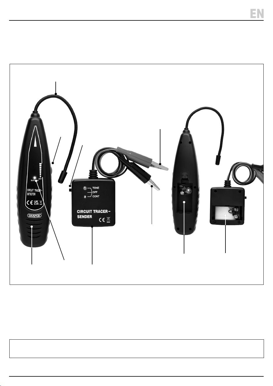
5. Identication
– 4 –
EN
(1) Receiver probe
(2) Circuit tester detector
(3) Battery light
(4) ON/OFF switch
(5) Sender switch
(6) Circuit tracer sender
(7) Detector battery compartment
(8) Sender Battery compartment
(9) (+) Positive (red) lead and clamp
(10) (-) Negative (black) lead and clamp
Please visit drapertools.com for our full range of accessories and consumables.
Carefully remove the product from the packaging and
examine it for any signs of damage that may have
occurred during shipment. If any part is damaged or
missing, do not attempt to use the product.
Please contact the Draper Helpline; contact details can
be found at the back of this manual.
(8)
(2)
(3)
(6)
(10)
(7)
(1)
(9)
(4)
(5)

6. Installing the battery
– 5 –
EN
7. Operation
1. To t or replace the battery unclip the battery
compartment (7) for the detector and (8) for the sender.
2. Fit 1 X 9V battery – ensuring that the battery is tted in
the correct +/- orientation.
3. Clip the cover back on.
1 Fig.
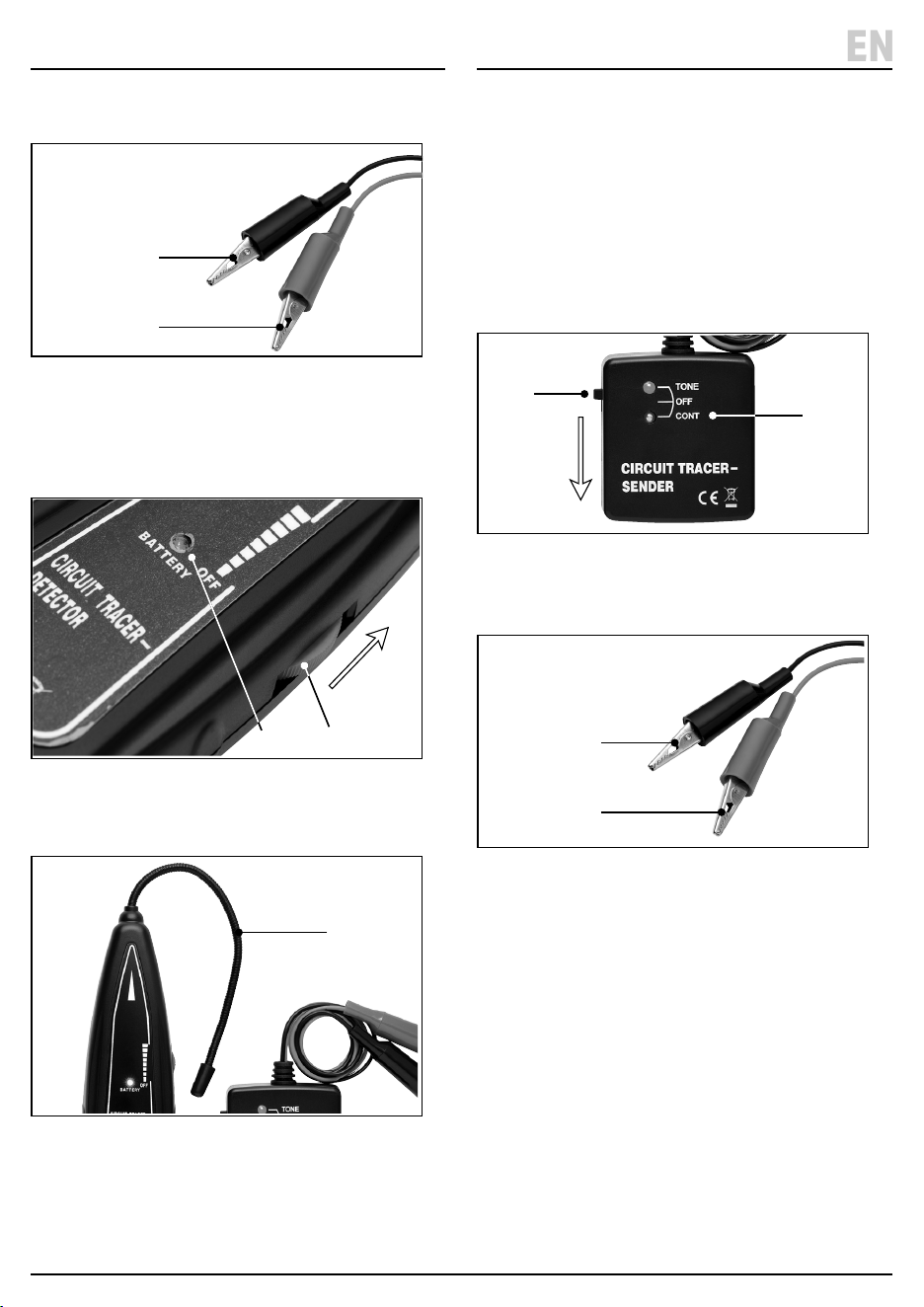
7.1 Detector Self-Check
Important: Before operating this product, read and
understand all the safety instructions listed in this
manual. Ensure that the product is fully assembled and
correctly prepared for use.
1. Before using the detector carry out the self checking
procedure.
2 Fig.
2. Push the Sender switch (5) up to the ‘TONE’ position
- the red light will come on.
3 Fig.
3. Then turn the ON/OFF thumb wheel (4) to switch on
the detector (2) – the red battery light (3) will come on.
• If the indicator lights do not come on check and
replace the battery.
4. Bring the receiver to the sender and the detector will
produce an audible signal to indicator both are
functioning correctly.
7.2 Using the Probe
4 Fig.
• The receiver probe (1) is made of coiled steel and can
be bent as required to reach dicult areas.
1. Depending on the circuit characteristic and the
receiver sensitivity setting the probe will pick up the
wire signal without direct contact.
2. However, it is recommended to achieve the best
detecting range that the probe (1) tip touches the
wire being traced either below or above it.
(7)
(8)
(1)
(4)(3)
(TONE)
(5)
7. Operation
– 6 –
EN
7.3 Wire Tracing
5 Fig.
1. Connect the black clip (10) to the ground and the red
clip (9) to the traced wire. (If a series connection is
required, connect the black clip to the battery
positive terminal and red clip to the traced wire).
6 Fig.
2. Turn the ON/OFF thumb wheel (4) to tune the
sensitivity until an audible signal can be heard.
7 Fig.
3. Move the receiver probe (1) as close as possible to the
wire to be traced and follow the audible signal.
• If the audible signal decreases or disappears there is
an open circuit or bad connection.
• If the audible signal is dicult to pick up increase the
sensitivity of the receiver.
7.4 Checking for Short Circuits
1. Disconnect the power and remove all loads to the wire
to be checked.
8 Fig.
2. Move the sender switch (5) down to the ‘CONT’
position.
9 Fig.
3. Connect the test leads to the wires to be checked.
4. If the resistance is less than 10k ohm the ‘CONT’ light
will be green. With no load the green light indicates
that wires are short circuited.
(10)
(9)
(3)
(4)
(1)
(10)
(9)
(CONT)
(5)

WARNING! Do not attempt to repair or service this product. Any servicing or repairs must be carried out by a
qualied person.
• Wipe the case with a damp cloth and a mild detergent. DO NOT use solvents or abrasives to clean the tester.
• Turn both the receiver and sender o when not in use and remove the batteries if stored for a long period of time.
• At the end of its working life, dispose of the product responsibly and in line with local regulations. Recycle where
possible.
• DO NOT burn or mutilate batteries; this may release toxic or corrosive substances.
• DO NOT dispose of this product with domestic waste; most local authorities provide appropriate recycling facilities.
9. Warranty
24 months
Visit drapertools.com/warranty for full details.
8. Maintenance, Storage and Disposal
– 7 –
EN

© Published by Draper Tools Limited© Published by Draper Tools Limited
Delta International
Delta International BV
Oude Graaf 8
6002 NL
Weert
Netherlands
Contact Details
Draper Tools
Draper Tools Limited
Hursley Road
Chandler’s Ford
Eastleigh
Hampshire
SO53 1YF
UK
Website: drapertools.com
Email: [email protected]
Product Helpline: +44 (0) 23 8049 4344
Telephone Sales Desk: +44 (0) 23 8049 4333
General Enquiries: +44 (0) 23 8026 6355
General Fax: +44 (0) 23 8026 0784
Please contact the Draper Tools Product Helpline for repair and servicing enquiries.