
Operator’s Manual
www.mechmaxx.com
MODEL: FMS60/72


TABLE OF CONTENTS
TABLE OF CONTENTS 1
IMPORTANT SAFETY INFORMATION 2
ROTATING DRIVELINE HAZARD
6
REQUIRED GUARDS AND SHIELDS
6
MISSING OR DAMAGED GUARD WARNING
6
SAFE OPERATING PRACTICES AROUND THE PTO
6
SUMMARY WARNING
6
FASTENER TORQUE GUIDELINES
8
TRACTOR COMPATIBILITY REQUIREMENTS
8
CONNECTING THE MOWER TO THE TRACTOR
8
PTO DRIVELINE SAFETY
8
PTO DRIVELINE INSTALLATION
9
CHECKING COLLAPSIBLE LENGTH
9
SHORTENING THE DRIVELINE
9
CHECKING MAXIMUM DRIVELINE EXTENSION
9
CHECKING PTO DRIVELINE CLEARANCE DURING OPERATION
10
TRANSPORT SAFETY
10
CRITICAL SAFETY WARNINGS
10
WORKING INSTRUCTIONS
11
OPERATING INSTRUCTIONS
11
LEVELING AND BELT ADJUSTMENT
13
MOWER LEVELING
13
BELT TENSION ADJUSTMENT
14
TO ADJUST TENSION:
14
BLADE REPLACEMENT PROCEDURE:
15
CUTTING HEIGHT ADJUSTMENT
15
LUBRICATION POINTS
16
BLADE SPINDLE BLADE SERVICE & CUTTING
HEIGHT ADJUSTMENT
14
EMERGENCY READINESS
TPERSONAL PROTECTIVE EQUIPMENT (PPE)
3
4
4
4
HIGH-PRESSURE HYDRAULIC SAFETY
PASSENGER SAFETY
4
4
TIRE HANDLING SAFETY
4
SAFETY AT ALL TIMES
2
DISCLAIMER AND LIMITATION OF LIABILITY
2
ROAD USE AND VISIBILITY
3
TRANSPORTING THE MOWER
3
RECOMMENDED SPEED LIMITS:
3
MAINTENANCE SAFETY
3
SAFE TRANSPORT AND MAINTENANCE GUIDELINES
PERSONAL SAFETY AND HAZARD AWARENESS
5
SAFETY DECALS
6
PTO DRIVELINE SAFETY INFORMATION
INTENDED USE
7
ABOUT THIS MANUAL
7
DIRECTIONAL REFERENCES
7
INFORMATION NOTICES
7
7
INTRODUCTION
8
ASSEMBLY & SET-UP
13
GENERAL OPERATING INSTRUCTIONS
16
MAINTENANCE & LUBRICATION
18
FEATURES & BENEFITS
19
TROUBLESHOOTING
20
TORQUE VALUES CHART
21
FMS60/72 PARTS DIAGRAM
21
FMS60/72 PARTS LIST
1
www.mechmaxx.com
TABLE OF CONTENTS

SAFETY AT ALL TIMES
DISCLAIMER AND LIMITATION OF LIABILITY
DANGER
IMPORTANT SAFETY INFORMATION
2
www.mechmaxx.com
•Read and understand this Operator’s Manual completely
before operating this equipment.
•Refer to the Safety Labels on the machine and carefully
read and follow all instructions provided.
•Do NOT allow anyone to operate this equipment unless
they have fully read and understood this manual and
have been properly trained in the safe operation of the
machine.
•The operator must be familiar with all controls and
functions of the implement and must operate the equip-
ment only from the tractor driver’s seat.
•Always ensure all guards and shields are properly
installed and secured before operation.
•Do not leave the tractor or implement unattended with
the engine running.
•Never dismount from a moving tractor.
•Do not allow anyone to stand between the tractor and
the implement while backing up.
•Keep hands, feet, and loose clothing away from all
power-driven parts.
•Wear snug-fitting clothing to prevent entanglement with
moving components.
•Watch for obstacles such as wires, trees, and other
hazards when raising or operating the implement.
•Do not carry passengers on the implement at any time.
•Look for the Safety Alert Symbol
•The Safety Alert Symbol indicates a potential hazard to
personal safety.
•When you see this symbol, be alert and carefully read the
message that follows.
•In addition to the design and configuration of the equip-
ment, hazard control and accident prevention depend
upon the awareness, concern, prudence, and proper
training of all personnel involved in the operation, trans-
port, maintenance, and storage of the equipment.
•Be Aware of Signal Words
•Signal words are used to identify the level of hazard
seriousness.
•For Your Protection
•Thoroughly read and understand the Safety Labels on the
equipment and follow all instructions noted on them.
•Shutdown and Storage
•Lower the implement to the ground.
•Place the tractor in park, shut off the engine, and remove
the ignition key.
•Detach and store the implement in an area where
children do not normally play.
•Secure the implement using blocks or supports to
prevent movement.
The manufacturer shall not be held liable for any damage,
injury, or loss resulting from misuse, improper installation,
unauthorized modification, or operation outside the
intended use of this equipment.
Indicates an imminently hazardous
situation which, if not avoided, will
result in death or serious injury.
WARNING
Indicates a potentially hazardous
situation which, if not avoided, could
result in death or serious injury.
CAUTION
Indicates a potentially hazardous
situation which, if not avoided, may
result in minor or moderate injury.
IMPORTANT SAFETY INFORMATION

3
www.mechmaxx.com
When operating the mower on public roads, ensure
adequate visibility at all times.
Use approved warning lights, reflectors, and turn signals
when required by local regulations, especially during
low-light conditions.
Always follow applicable state and local traffic laws.
The recommended maximum transport speed is 20 mph
(32 km/h).
Reduce speed on uneven or rough surfaces to maintain full
control of the tractor and mower.
Avoid sudden stops, as rapid braking may cause the
mower to sway or become unstable, particularly if the
mower is not equipped with its own braking system.
Up to 20 mph when the mower weight does not exceed
the tractor weight
Up to 10 mph when the mower weight exceeds the tractor
weight
Notice:
The combined towed load should never exceed twice the
tractor’s weight.
Perform maintenance only after fully understanding the
required procedures.
Use proper tools and follow recommended service practic-
es.
Lower the mower to the ground, shut off the tractor
engine, and remove the ignition key before servicing.
Allow all components to cool before inspection or repair.
Never lubricate or adjust the mower while it is in opera-
tion.
Replace damaged or worn parts only with components
that meet original specifications.
Keep the mower free of excess grease, oil, and debris.
Ensure all tools and loose parts are removed before
returning the mower to service.
ROAD USE AND VISIBILITY
TRANSPORTING THE MOWER
RECOMMENDED SPEED LIMITS:
MAINTENANCE SAFETY
SAFE TRANSPORT AND MAINTENANCE GUIDELINES
SAFE TRANSPORT AND MAINTENANCE GUIDELINES

4
www.mechmaxx.com
Be prepared for unexpected situations.
Keep basic emergency supplies, such as a first aid kit and
fire extinguisher, within easy reach.
Know how to quickly contact emergency services and
nearby medical facilities.
Wear protective clothing and safety gear appropriate for
the task being performed.
Do not wear loose or dangling garments that could
become entangled in moving parts.
Prolonged exposure to loud operating noise may cause
hearing damage; use approved hearing protection when
necessary.
Safe operation requires full attention—do not use head-
phones or devices that limit awareness while operating
the mower.
Hydraulic fluid under pressure can penetrate the skin and
cause severe injury.
Always relieve hydraulic pressure before disconnecting
hoses or performing service work.
Inspect hoses, fittings, and connections to ensure they
are secure and in good condition before pressurizing the
system.
Use cardboard or similar materials to detect leaks—nev-
er use hands or other body parts.
Wear suitable hand and eye protection when working on
hydraulic components.
If hydraulic fluid is injected into the skin, seek immediate
medical attention.
Tire servicing involves potential hazards and should be
carried out only by trained individuals using proper equip-
ment.
When inflating tires, use a clip-on air chuck and maintain
a safe distance.
Stay clear of the tire assembly during inflation.
Use appropriate lifting or handling equipment when
installing or removing wheels to manage their weight
safely.
EMERGENCY READINESS
PERSONAL PROTECTIVE EQUIPMENT (PPE)
HIGH-PRESSURE HYDRAULIC SAFETY
This equipment is designed for a single operator only.
Do not allow riders or children on the mower or tractor at
any time.
PASSENGER SAFETY
TIRE HANDLING SAFETY
PERSONAL SAFETY AND HAZARD AWARENESS
PERSONAL SAFETY AND HAZARD AWARENESS
5
www.mechmaxx.com
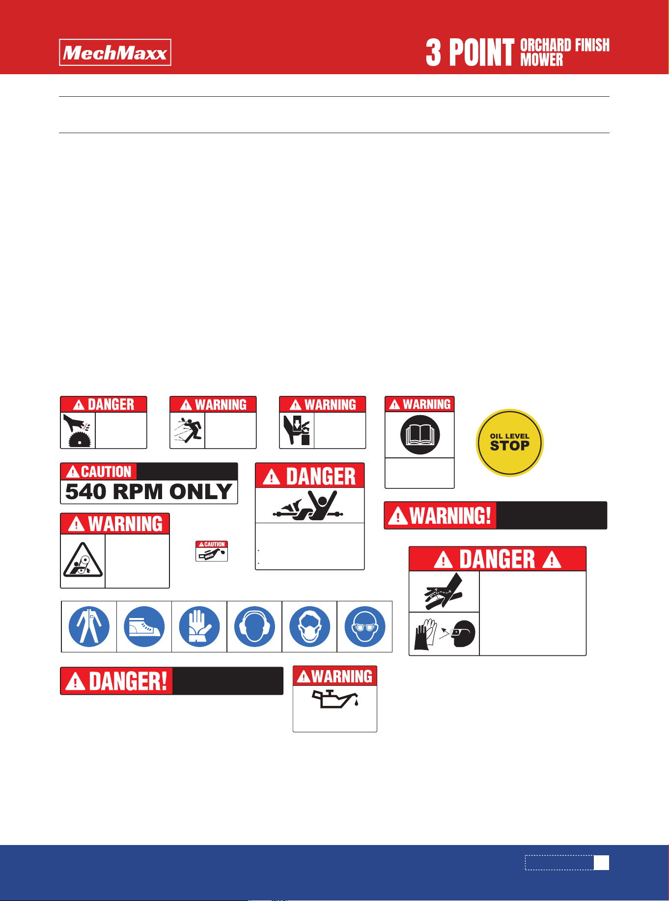
SAFETY DECALS
SAFETY DECALS
This mower is supplied with safety decals installed at the factory.
These decals are intended to alert operators to potential hazards and promote safe operation of the equipment.
Always read and follow the information provided on each decal.
1.Review this section to identify the correct decal locations.
Any decal that becomes damaged, missing, or unreadable must be replaced promptly.
Replacement decals should be obtained through an authorized dealer.
2.When components are replaced or new parts are installed during service or repair, corresponding safety decals must
be applied to the new components where required.
Ensure that appropriate decals are included when ordering replacement parts.
3.Refer to the illustrations in this section for proper decal placement.
Decal Installation Instructions:
a. Thoroughly clean the surface where the decal will be applied.
b. Lightly apply soapy water to the mounting surface to allow positioning.
c. Remove the backing paper and press the decal firmly into place.
d. Use a flat-edged tool, such as a plastic card, to remove air bubbles and ensure full adhesion.
ROTATING
BLADES
KEEP HANDS
AWAY
KEEP BYSTANDERS AWAY.
DO NOT OPERATE NEAR PEOPLE.
FLYING
OBJECTS
HAZARD
KEEP CLEAR.
To avoid Injury or Machine Damage:
Operate only with 540 rpm PTO
PINCH POINT
HAZARD
KEEP CLEAR
Read and
understand
operator's manual
before using this
machine.
All driveline guards, tractor, and equipment
shields in place.
ROTATING DRIVELINE CONTACT CAN
CAUSE DEATH KEEP AWAY!
DO NOT OPERATE WITHOUT :
Drivelines securely attached at both ends.
C
H
E
C
K
G
E
A
R
B
O
X
B
E
F
O
R
E
S
T
A
R
T
U
P
!
!
Do not open or remove
safety shields while
engine is running.
BELT DRIVE:
HAND AND ARM
ENTANGLEMENT
HAZARD.
USE EXTREME CAUTION WHEN OPERATING
IN REVERSE. LOOK BEHIND AND KEEP
BYSTANDERS AWAY
High Pressure Fluid Hazard.
High pressure fluid leak will pierce skin.
Release pressure before working on
system.
Fluid injected into skin will injure or kill.
Detect leaks with wood or cardboard.
Wear sturdy gloves and goggles.
NEVER use fingers.
Fluid injected in skin must be surgically
removed by trained doctor immediately
or gangrene will result.
0.5L (0.53 quarts) is required.Gearoil type: 80W-90
MUST ADD GEARBOX OIL
BEFORE FIRST USE

6
www.mechmaxx.com
The mower is powered through a PTO driveline that rotates during operation.
A rotating driveline presents a serious entanglement hazard. Contact with the driveline can result in severe injury or
death.
Always stay clear of the PTO driveline whenever the tractor engine is running or the PTO is engaged. Never step over, reach
across, or work near a rotating driveline.
Do not operate the mower unless all driveline safety guards and shields are correctly installed and in good condition.
Before operation, ensure that:
•All PTO and driveline guards are in place on both the tractor and the mower
•The driveline is securely connected at both ends
•Protective guards are free to rotate independently of the driveline shaft
•Guards and shields are designed to reduce the risk of entanglement and must never be removed or modified.
Operation of the mower is strictly prohibited if any PTO or driveline guard is missing, damaged, or not functioning properly.
If a guard is missing or damaged:
•Shut down the tractor immediately
•Disengage the PTO
•Repair or replace the guard before resuming operation
•Never attempt to operate the equipment with exposed rotating components.
Engage the PTO only when seated in the operator’s position
Disengage the PTO, shut off the engine, and remove the ignition key before performing adjustments, maintenance, or
inspection
Wait until all rotating parts have come to a complete stop before approaching the driveline
Keep clothing, hair, hands, and tools away from the PTO area at all times
Failure to follow PTO driveline safety instructions can result in serious injury or death.
Always maintain proper guarding and keep a safe distance from rotating components during operation.
ROTATING DRIVELINE HAZARD
REQUIRED GUARDS AND SHIELDS
MISSING OR DAMAGED GUARD WARNING
SAFE OPERATING PRACTICES AROUND THE PTO
SUMMARY WARNING
PTO DRIVELINE SAFETY INFORMATION
PTO DRIVELINE SAFETY INFORMATION
7
www.mechmaxx.com
INTRODUCTION
INTRODUCTION
Thank you for choosing this Orchard Finish Mower.
This machine has been engineered and manufactured using quality materials and skilled workmanship. With proper setup,
routine maintenance, and safe operation, the mower will delivers power.
This Orchard Finish Mower is manufactured using quality materials and skilled workmanship. Proper setup, routine main-
tenance, and safe operation practices will help ensure dependable performance and long service life.
This finish mower is designed for light-duty mowing applications, including orchards, lawns, gardens, and roadside main-
tenance.
It is intended for use with tractors equipped with a three-point hitch and rated between 25 and 50 horsepower.
All models are fitted with Finish mower blades to deliver a clean and consistent cut across a wide range of mowing condi-
tions.
This Operator’s Manual provides important information regarding safety, assembly, operation, adjustment, maintenance,
and troubleshooting.
Read and follow all instructions before operating the equipment.
Product specifications and components may be updated over time as part of ongoing improvements.
Replacement manuals may be obtained through an authorized dealer.
INTENDED USE
ABOUT THIS MANUAL
Unless otherwise noted, references to “left” or “right” in this manual are determined from the operator’s position when
facing the normal direction of travel.
IMPORTANT:
Highlights information that is critical to the current topic and must be reviewed before proceeding.
DIRECTIONAL REFERENCES
NOTE:
Provides additional information intended to assist the operator.
INFORMATION NOTICES
Model:
Weight:
PTO Speed:
Year of MFG:
Working Width:
Hitch Type:
FMS60
540 RPM
Serial Number:
60 in
Cat 1
www.mechmaxx.com
ORCHARD FINISH
MOWER
8
www.mechmaxx.com
ASSEMBLY & SET-UP
Proper tightening torque is required for all bolts and fasteners.
Refer to the torque specification table for standard bolt sizes listed on page 21 before securing hardware.
FASTENER TORQUE GUIDELINES
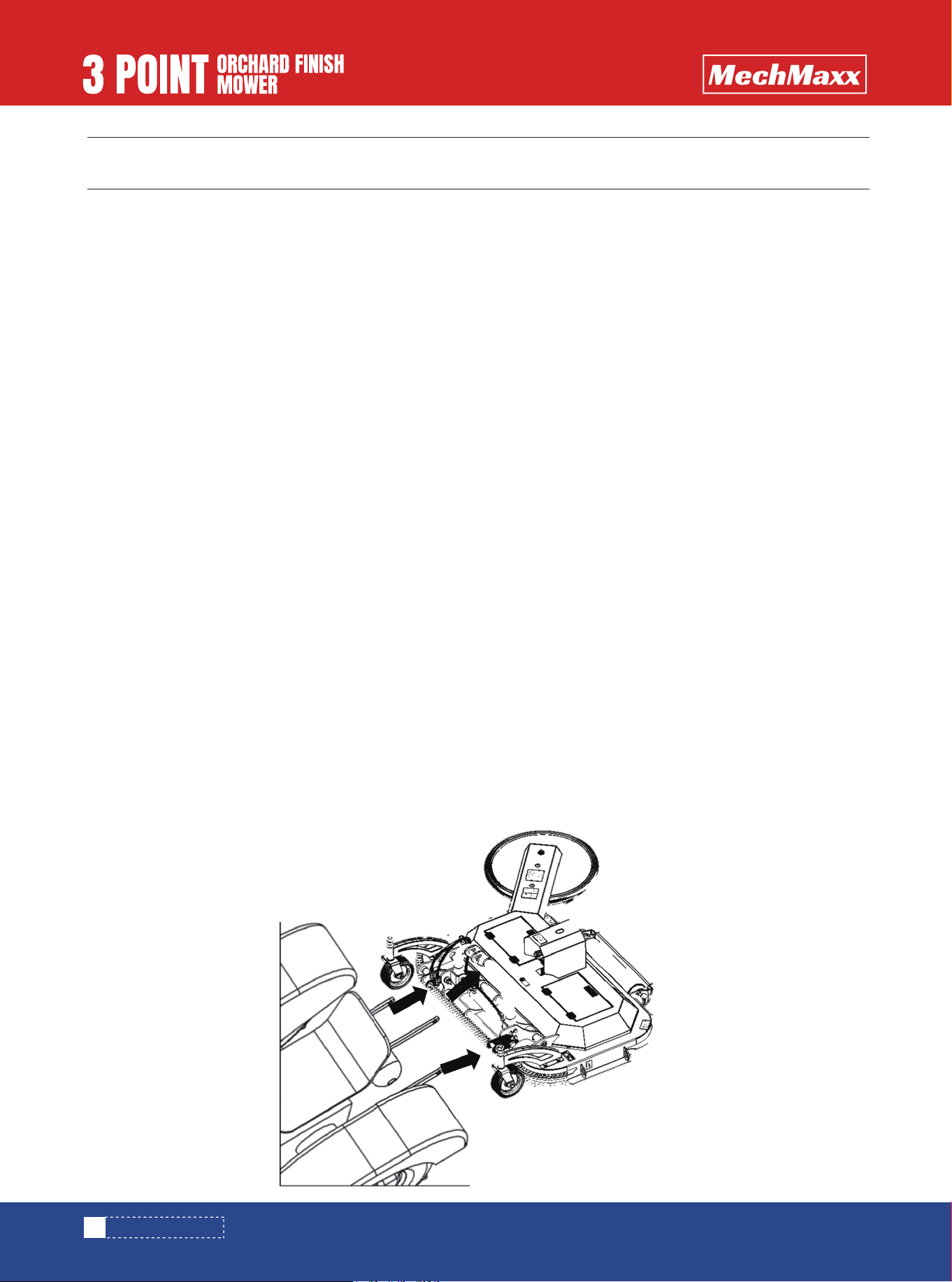
The three-point hitch is factory installed and attached to the mower frame.
HITCH INSTALLATION
Use only tractors that fall within the specified horsepower range and hitch category.
The tractor’s lower three-point arms must be properly stabilized to prevent lateral movement during operation.
Verify that the tractor meets the following requirements before connecting the mower:
•Power output: FMS72 35-65 HP, FMS60 25-50HP
•Hitch system: Category I three-point hitch
•PTO speed: 540 rpm
Before installation, confirm that the tractor drawbar does not interfere with the mower.
Remove or reposition the drawbar if required.
Attach the mower using the tractor’s three-point hitch system.
Secure all hitch connections with appropriate pins and retaining clips.
Once connected, slightly raise the mower, retract the jack stands fully, and lock them in place.
Adjust the hitch arms and top link until the mower deck is level.
Never engage the PTO while installing or removing the driveline, or while standing near rotating driveline components.
Contact with a rotating driveline can result in serious injury or entanglement.
TRACTOR COMPATIBILITY REQUIREMENTS
CONNECTING THE MOWER TO THE TRACTOR
PTO DRIVELINE SAFETY
ASSEMBLY & SET-UP

9
www.mechmaxx.com
Park the tractor on level ground and raise the mower using the three-point hitch until the gearbox shaft aligns with the
tractor PTO shaft. Support the mower at this height.
Shut the engine off, set the parking brake, and remove the key.
Attach the implement end of the driveline to the gearbox shaft and lock it in place.
Attach the tractor end to the PTO shaft and confirm the locking device is fully engaged.
Secure the driveline safety chains to the tractor and mower frame, then re-latch them to the shields.
Move the driveline slightly to confirm both ends are fully seated.
PTO DRIVELINE INSTALLATION
The driveline must have adequate telescoping clearance. An over-length driveline can bind and damage the tractor or
mower.
With the driveline level, verify at least 1 inch of clearance at the universal joint shield. If clearance is insufficient, the
driveline must be shortened before use.
CHECKING COLLAPSIBLE LENGTH
Separate the inner and outer sections. Mark equal cut lengths on both shafts and shields following the 1-inch reference.
Remove the driveline, cut the inner and outer shafts and shields by the same amounts, deburr all edges, clean thoroughly,
and reassemble.
Recheck extended length before operation.
SHORTENING THE DRIVELINE
After confirming sufficient telescoping clearance, verify that the driveline maintains adequate spline engagement when
fully extended.
At maximum extension, the overlap between the inner and outer profile tubes must be no less than one-third of the free
tube length, with both tubes remaining equal in length.
Apply multi-purpose grease to the inside of the outer tube before assembly.
Once assembled, measure and record the maximum permissible driveline length for reference.
Raise and lower the mower to locate the condition of maximum extension.
If necessary, limit three-point hitch lift height to prevent over-extension.
CHECKING MAXIMUM DRIVELINE EXTENSION
Outer Shielding has been removed for clarity.
FREE LENGTH
FREE LENGTH
1 / 3 1 / 3 1 / 3 1 / 3 1 / 3
OVERLAP
TRACTOR END
OUTER PROFILE INNER PROFILE
MAXIMUM ALLOWABLE LENGTH
IMPLEMENT END
ASSEMBLY & SET-UP
Do not use Mowers as a working platform. the mower is not properly designed or guarded for this. Using
the mower as a working platform can cause serious injury or death.
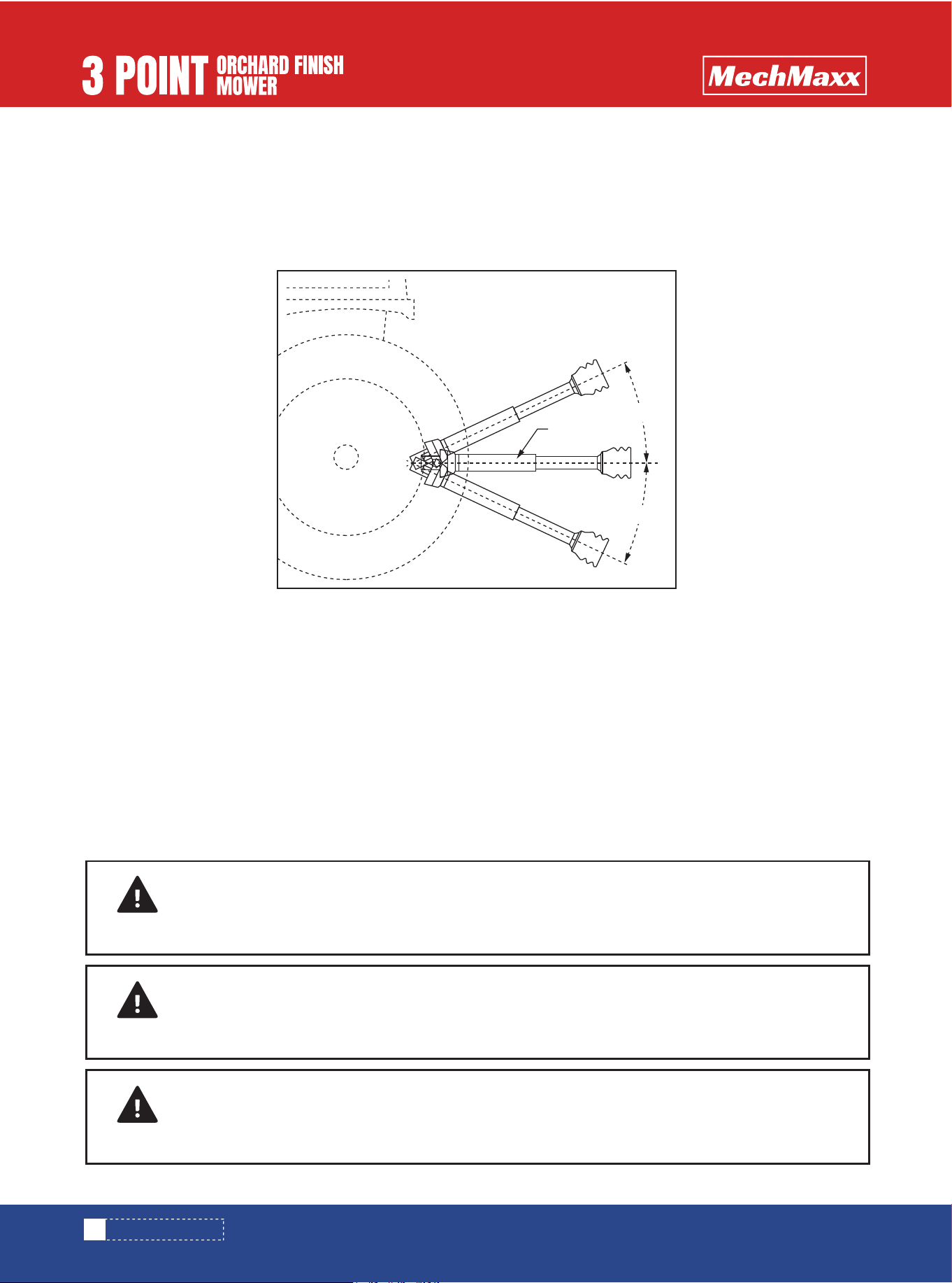
During mower lift and lowering, inspect for adequate clearance between the driveline and tractor drawbar.
Ensure the driveline operating angle does not exceed 25 degrees upward or downward under maximum movement condi-
tions.
If interference or excessive angle is observed, adjust the three-point hitch height accordingly.
When transporting the mower, comply with all applicable traffic regulations.
Ensure sufficient clearance between the driveline and tractor components.
Reduce speed during turns and when operating on uneven or sloped terrain.
TRANSPORT SAFETY
CHECKING PTO DRIVELINE CLEARANCE DURING OPERATION
Never engage the PTO while connecting or disconnecting the driveline.
Operate the mower only with all shields in place.
Do not operate damaged driveline components.
Never allow riders on the mower.
CRITICAL SAFETY WARNINGS
10
www.mechmaxx.com
DANGER
Do not operate and/or travel across steep inclines where a tractor can roll-over resulting in serious
injury or death. Consult your tractor’s manual for acceptable inclines the tractor is capable of traveling
across.
DANGER
DANGER
Do not use Mowers to lift or carry objects. Lifting and/or carrying objects can result in damage to the
mower , serious bodily injury, or death.
DRIVELINE
LEVEL
25°
25°
ASSEMBLY & SET-UP

1.Clear area to be worked of objects and debris that might be picked up and thrown by the mower blades.
2.Make the following machine checks before operating the mower .
•All hook-up pins should be secured.
•All shields should be in place and secured.
•All bolts and lock nut s should be present and tight.
•Make sure the blades are not be broken or loose.
Proper servicing and adjustments are the key to the long life of any machine. With careful and systematic inspection of
the mower , costly maintenance, time, and repair can be avoided.
! Before beginning to work, the following inspection and checks should be performed:
1.Check oil level in gearbox.
2.Check that all plugs in gearbox have been replaced and tightened properly.
3.Be sure all Mowers blades, bolts, and lock nut s are tight.
4.Be certain all guards and shields are in place and secure.
5.Grease driveline shaft and all other grease fittings.
6.Clear area to be worked of rocks, branches, and other foreign objects.
7.Lower Mowers to ground. Set tractor throttle at approximately 1/4 open. Engage PTO to start blades rotating.
8.Operate with 540 rpm PTO tractor. At first begin working at a slow forward speed and shift up until the desired speed
is achieved maintaining 540 rpm PTO. The Blade spindle blades will cut better at full blade speed than at reduced throttle.
9.After working the first 50 feet, stop and check to see that the mower is adjusted properly.
10.Do not make sharp turns or attempt to back up while Mowers is on the ground.
11.Never work close to or on steep slopes.
12.Do not engage PTO with Mowers in the fully raised position. Do not engage PTO at full throttle. Do not lift Mowers with
PTO engage.
13.Do not allow anyone including yourself near the mower when it is operating.
14.Periodically check for foreign objects wrapped around the Blade spindle shaft and remove them after disengaging PTO,
turning off tractor, and removing ignition key.
WORKING INSTRUCTIONS
OPERATING INSTRUCTIONS
11
www.mechmaxx.com
Always disengage PTO, engage parking brake, shut tractor engine off, remove switch key, and wait for
blades to come a complete stop before dismounting from tractor.
WARNING
Do not over speed PTO or machine damage may result. This Mowers is designed to be used only with a
tractor having a 540 RPM rear PTO.
CAUTION
ASSEMBLY & SET-UP
12
www.mechmaxx.com
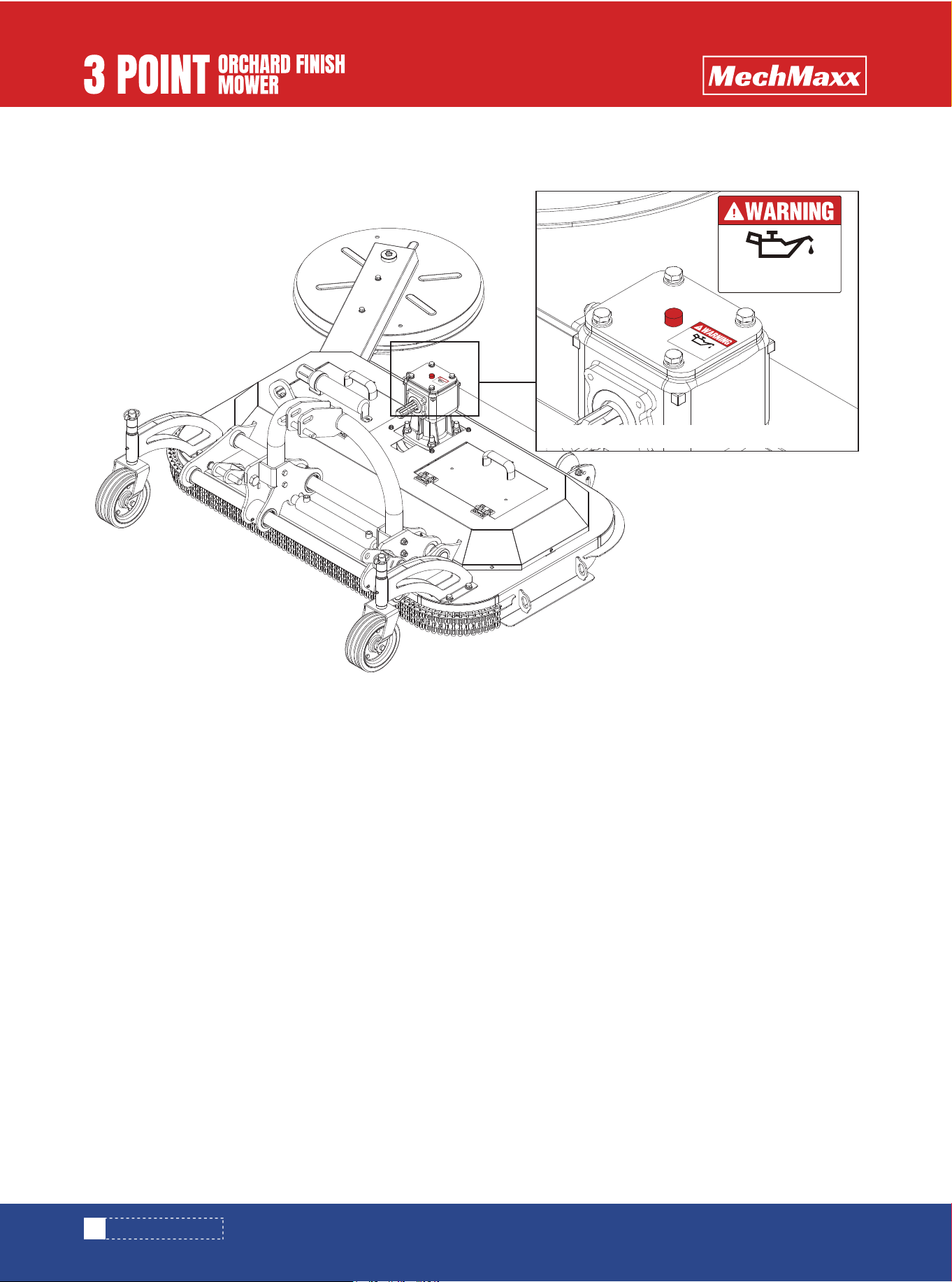
UNIT IS SHIPPED WITHOUT OIL IN THE GEARBOX AND WITHOUT GREASE IN THE GREASE FITTINGS.
ADD OIL AND GREASE BEFORE OPERATION.
0.5L (0.53 quarts) is required.Gearoil type: 80W-90
MUST ADD GEARBOX OIL
BEFORE FIRST USE
0.5L (0.53 quarts) is required.Gearoil type: 80W-90
MUST ADD GEARBOX OIL
BEFORE FIRST USE
0.5L (0.53 quarts) is required.Gearoil type: 80W-90
MUST ADD GEARBOX OIL
BEFORE FIRST USE
0.5L (0.53 quarts) is required.Gearoil type: 80W-90
ASSEMBLY & SET-UP

13
www.mechmaxx.com
After reviewing this Operator’s Manual, completing the pre-operation checklist, properly attaching the mower to the
tractor, and adjusting the hitch position and Cutting height, the mower is ready for operation.
Before beginning work, perform a running operational safety check. If at any time a malfunction or abnormal condition is
detected in the mower or tractor, immediately disengage the PTO, shut off the tractor engine, remove the ignition key,
and correct the issue before continuing operation.
Ensure the tractor parking brake is engaged, the PTO is disengaged, and the mower is resting on the ground. Start the
tractor and allow the engine to run at low idle. Using the tractor’s hydraulic lift control, raise the mower to the transport
position while ensuring the PTO driveline is not binding and does not contact the mower frame. Lower the mower to the
selected Cutting height and, with the engine still at low idle, engage the PTO.
Once the PTO is engaged and operating smoothly, gradually increase engine speed until the tractor reaches the rated PTO
speed of 540 RPM. Slowly raise the mower to transport height to verify that the driveline operates smoothly without
binding or vibration. Reduce engine speed to low idle, disengage the PTO, and set the tractor’s hydraulic lift stop so the
mower can be returned consistently to the same cutting and transport positions.
The mower is now ready for field operation. Operate only in areas that have been inspected and are reasonably free of
debris, rocks, and hidden obstacles. Never assume an area is clear. If the mower strikes an object, immediately disen-
gage the PTO, shut off the tractor, remove the ignition key, and inspect the mower before resuming operation.
Normal operating ground speed is typically between 2 and 5 mph, depending on grass density and terrain. Maintain full
PTO speed to achieve a clean and even cut, adjusting tractor ground speed as needed. Lower ground speeds generally
improve cut quality, especially in heavier grass conditions.
Operate with caution on slopes. Always mow up and down slopes rather than across them, and avoid steep inclines.
Reduce speed when turning, avoid sharp turns, and cross uneven terrain slowly and diagonally to maintain stability.
Frequently check behind the tractor to monitor mower performance and operating conditions.
To begin mowing, reduce engine speed, ensure the mower is resting on the ground at the selected Cutting height, engage
the PTO, then increase engine speed to the rated PTO speed. Plan mowing paths in advance to allow smooth, safe turns
and consistent coverage. Adjust ground speed as needed to achieve the desired cutting results. With proper operation
and practice, the mower will deliver reliable performance and a high-quality finish.
Safety Precautions
Before performing any adjustments, park the tractor on level ground, engage the parking brake, shut off the engine,
remove the ignition key, and disengage the PTO.
If the mower must be raised for adjustment, support it securely. An unsupported implement may fall and cause serious
injury.
Proper leveling is achieved using the tractor’s lower lift arms and top link:
Raise the mower slightly off the ground (approximately 1–2 in)
Stabilize the lower arms to minimize side-to-side movement
Adjust the lower arms until the mower is level from left to right
Adjust the top link so the upper hitch point is vertical or slightly rearward of the lower hitch pins
Cycle the three-point hitch up and down to verify adequate clearance from tires, frame, and drawbar
LEVELING AND BELT ADJUSTMENT
MOWER LEVELING
GENERAL OPERATING INSTRUCTIONS
GENERAL OPERATING INSTRUCTIONS
14
www.mechmaxx.com
Excessive belt tension can shorten belt life and place undue stress on drive components.
Inspect belt tension after the first 20 hours of operation and every 40 hours thereafter
Apply moderate force at the midpoint between pulleys; correct deflection is approximately 3/8 in
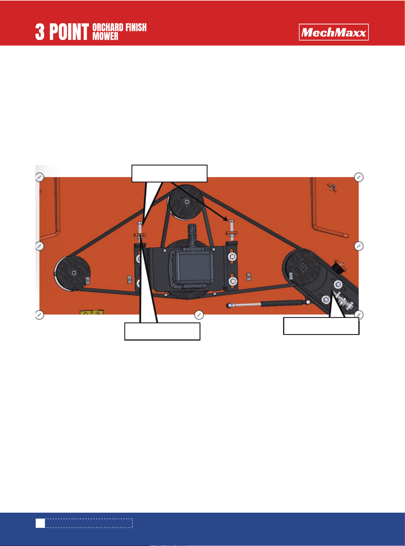
BELT TENSION ADJUSTMENT
BLADE SPINDLE BLADE SERVICE & CUTTING HEIGHT ADJUSTMENT
Loosen gearbox mounting hardware
Adjust the belt tensioning bolts evenly
Retighten all mounting bolts and tension hardware securely
Blade spindle Blade Inspection and Replacement
Inspect Blade spindle blades regularly to ensure they are secure and in serviceable condition. Replace any blade that is
worn, bent, or damaged.
Important:
•Replacement blades must match the original blade weight to maintain Blade spindle balance
•Use only blades meeting original equipment specifications
TO ADJUST TENSION:
GENERAL OPERATING INSTRUCTIONS
Belt Tension Bolt
Belt Tension Bolt
Belt Tension nut
15
www.mechmaxx.com
BLADE REPLACEMENT PROCEDURE:
CUTTING HEIGHT ADJUSTMENT
GENERAL OPERATING INSTRUCTIONS
•Remove the blade mounting hardware using the appropriate wrench
•Remove the worn blade
•Install the replacement blade using the original fasteners
•Tighten all hardware to the specified torque
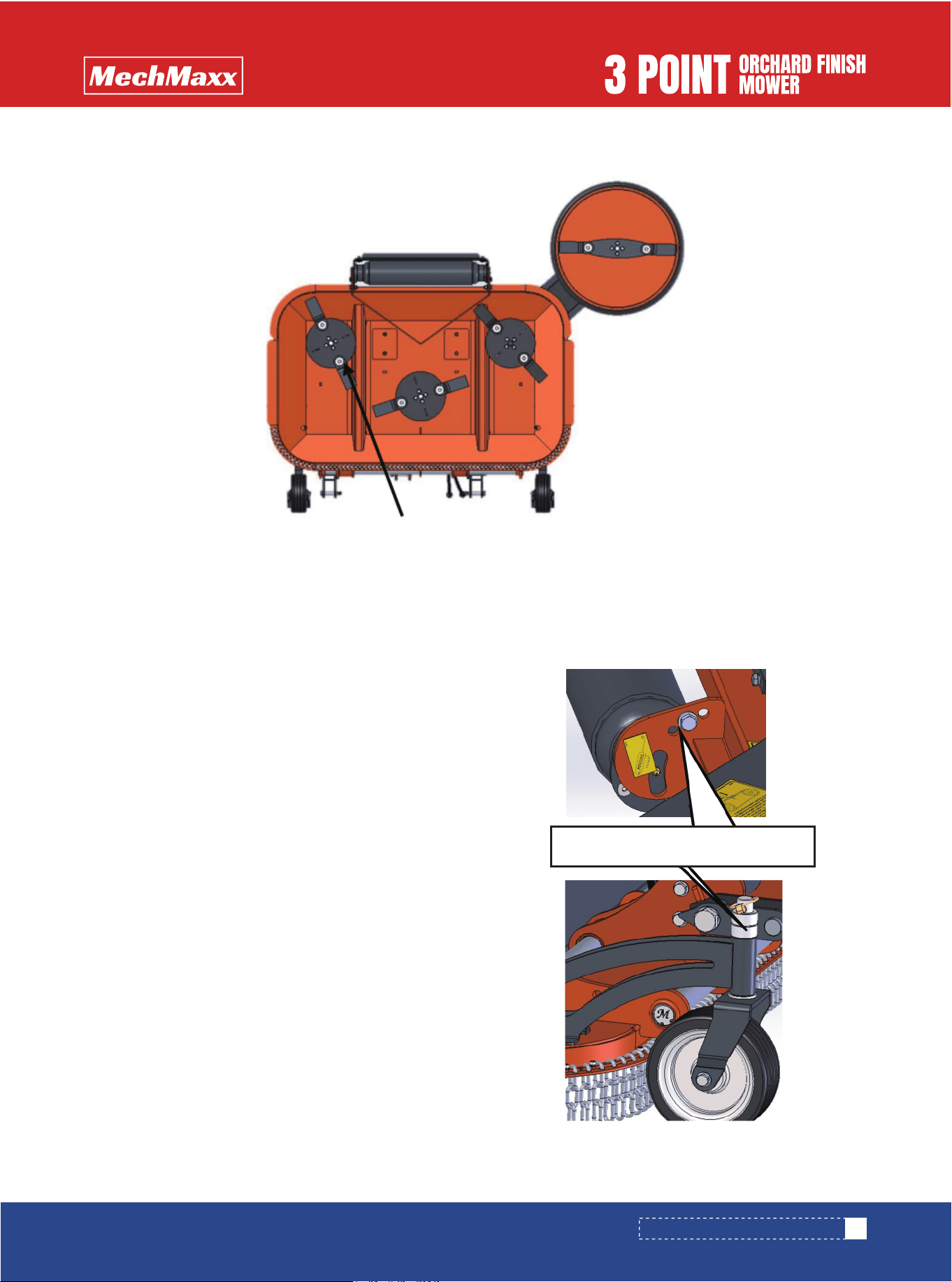
Cutting height is controlled by the position of the rear roller
and adjustment plates.
•Remove the mounting bolts on both sides of the rear roller
•Raise or lower the roller evenly to the desired height
•Reinstall and torque all fasteners securely
•Adjust spacer sleeves on the wheel mounting shaft as
required
•Verify that blades do not contact the ground; readjust if
necessary to prevent premature wear
The depth of work adjustment
Bolt M10*40, Special shim and locknut
16
www.mechmaxx.com
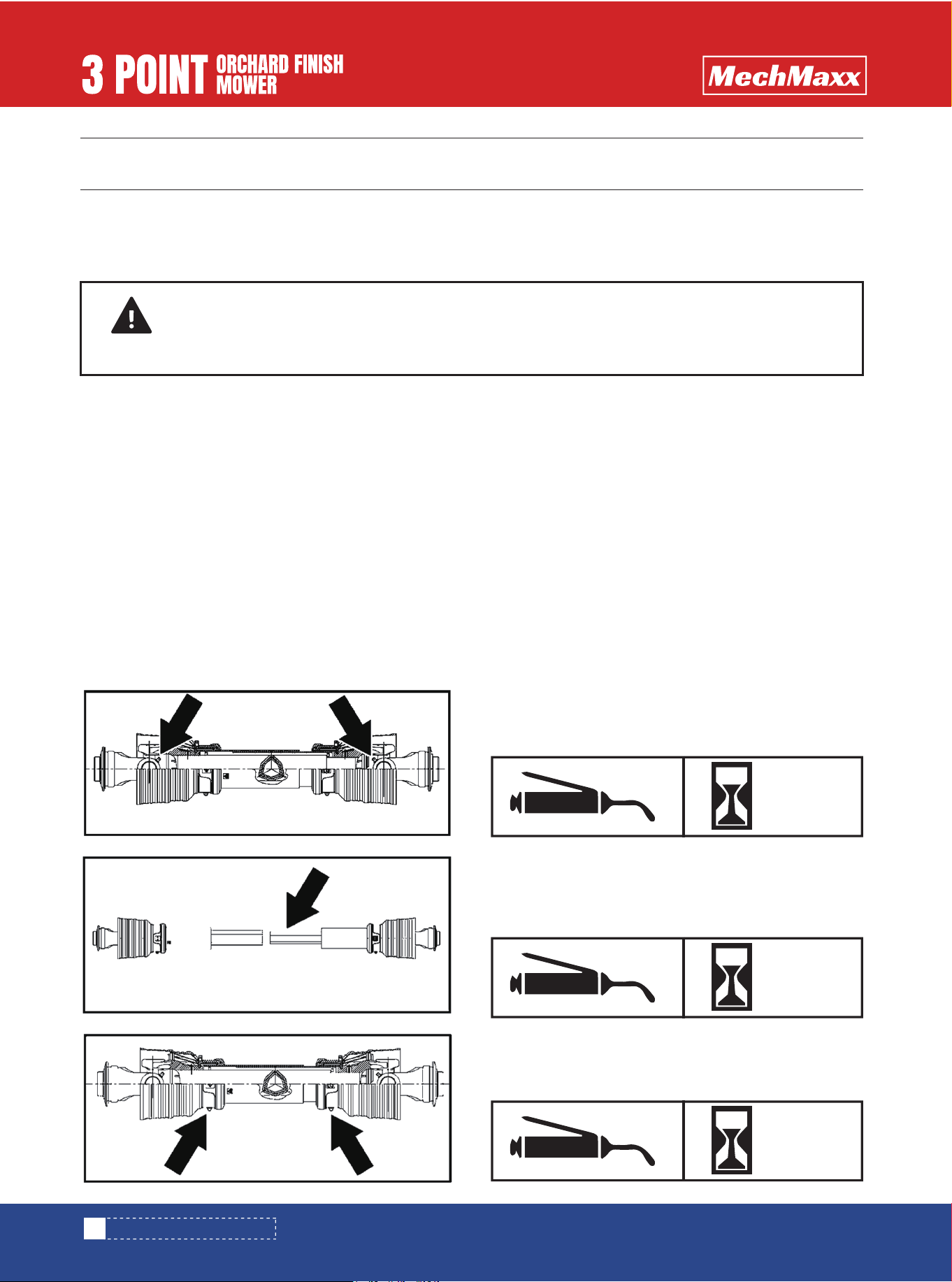
LUBRICATION POINTS
Driveline Shaft U-Joints
It is good practice to clean off any dirt and grease that may have accumulated on the mower and to inspect and make
necessary repairs before parking the unit at the end of the working season and for long periods. This will help ensure that
the mower will be ready for use the next time you hook up to it.
1. Remove any dirt and grease that may have accumulated on the mower and moving parts. Scrape off compacted dirt
from under the hood and then wash the surface thoroughly with a garden hose.
2. Check Blade spindle blade and blade bolts for wear and replace if necessary. See “Blade spindle blade Replacement” on
page 17.
3. Inspect Mowers for loose, damaged, or worn parts and adjust or replace as needed.
4. Replace all damaged or missing labels.
5. A light coat of oil or grease may also be applied to areas where paint has worn off to minimize oxidation.
6. Store equipment on a level surface in a clean, dry place. Inside storage will reduce maintenance and make for a longer
mower life. Position the unit on a flat surface with jack stands lowered to a suitable 3-Point height. Ensure that the main
frame is stable.
7. Store driveline end off the ground.
Type of Lubrication: Multi-purpose Grease Quantity - 4 to
8 Pumps
Driveline Profiles
Type of Lubrication: Multi-purpose Grease Quantity -Clean
& coat inner profile tube of driveline with a light film of
grease and then reassemble.
MAINTENANCE & LUBRICATION
MAINTENANCE & LUBRICATION
DANGER
Always disconnect the main driveline from tractor PTO and secure Mowers in the up position with solid
supports before servicing underside of the mower.
25
HOURS
25
HOURS
Inner Tube Bearings
Type of Lubrication: Multi-purpose Grease Quantity - As
Required
25
HOURS
17
www.mechmaxx.com
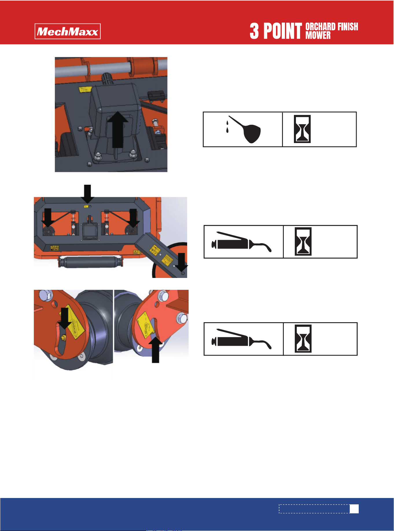
Gearbox Lubrication
MAINTENANCE & LUBRICATION
Type of Lubrication: 8OW-90 Gear
Add visual to the center of the gear oil Reinstall plugs and
tighten.
Do not overfill!
The Pulley gearing
Type of Lubrication: Multi-purpose Grease
25
HOURS
The bearing seat
Type of Lubrication: Multi-purpose Grease
25
HOURS
AS
REQUIRED

FEATURES & BENEFITS
18
www.mechmaxx.com
Features Benefits
Cutting width
3-Point screw type hitch can be
Hydraulic cylinder displacement
540 RPM cast iron gearbox with reverse
running clutch
Reverse Blade spindle rotation
Height adjusting roller
Standard scrapers on rear height adjusting
roller
Dual drivelines front and rear
60"–72", a good cutting width for many applications.
Easily offset the hitch for a closer cut alongside buildings, fences,
roadsides, and for getting
Through the hydraulic cylinder, conveniently swing the mower to cut
the slope and effectively avoid obstacles.
Enables the Blade spindle to free swing to a stop when the tractor
PTO has been turned off.
Brings the cut material up and over which allows it to be dispersed
more evenly.
Rear height adjusting roller with greaseable bearings and tapered
ends to prevent gouging during turns.
Choose front or rear driveline to meet your requirements to the
maximum extent.
Keeps roller clean for consistent Cutting height.
FEATURES & BENEFITS

TROUBLESHOOTING
19
www.mechmaxx.com
Problem Solution
Belt slipping
Patches of uncut to land
Excessive vibration
Gearbox noisy
blades scalping grass
Tractor loaded down by Mowers
Uneven cut
Unplug and clean Mowers deck.
Remove belt guard and clean sheaves.
Replace belt
Raise Crushing height by adjusting .
Change broken pattern.
Reduce speed turns.
Shift to a lower gear.
Level Mowers .
Replace missing blades or hammers
Mow at full throttle (540 PTO rpm).
Shift to a lower gear.
Clean Mowers .
Mow at full throttle (540 PTO rpm), check PTO speed, and tractor engine.
Shift transmission to a lower gear.
Tighten belts.
Replace missing blades.
Replace blades.
Replace drive belt.
Replace pulleys or align.
Remove belt guard & clean debris from belt area & sheaves.
Check lubricant level.
Do not try to clean rear discharge area when Mowers is running. Bodily harm may occur!
CAUTION
TROUBLESHOOTING

TORQUE VALUES CHART
M8×1
M10×1.25
M12×1.25
M14×1.5
M16×1.5
M18×1.5
M20×1.5
M22×1.5
M24×2
M27×2
M30×2
11
22
38
60
88
128
178
237
303
443
614
19
38
67
107
158
227
318
421
539
789
1091
27
55
94
148
222
319
447
592
758
1109
1535
32
65
113
178
266
384
536
711
910
1332
1842
Metric Bolt Tightening Torques (ft-lb)
6.8
Bolt Grade
Fine Thread Bolts
8.8 10.9 12.9
20
www.mechmaxx.com
Note: Torque values are approximate and provided for reference only.
Always follow fastener manufacturer specifications.
Torque values shown are metric fasteners converted to ft-lb for reference.
TORQUE VALUES CHART
21
www.mechmaxx.com
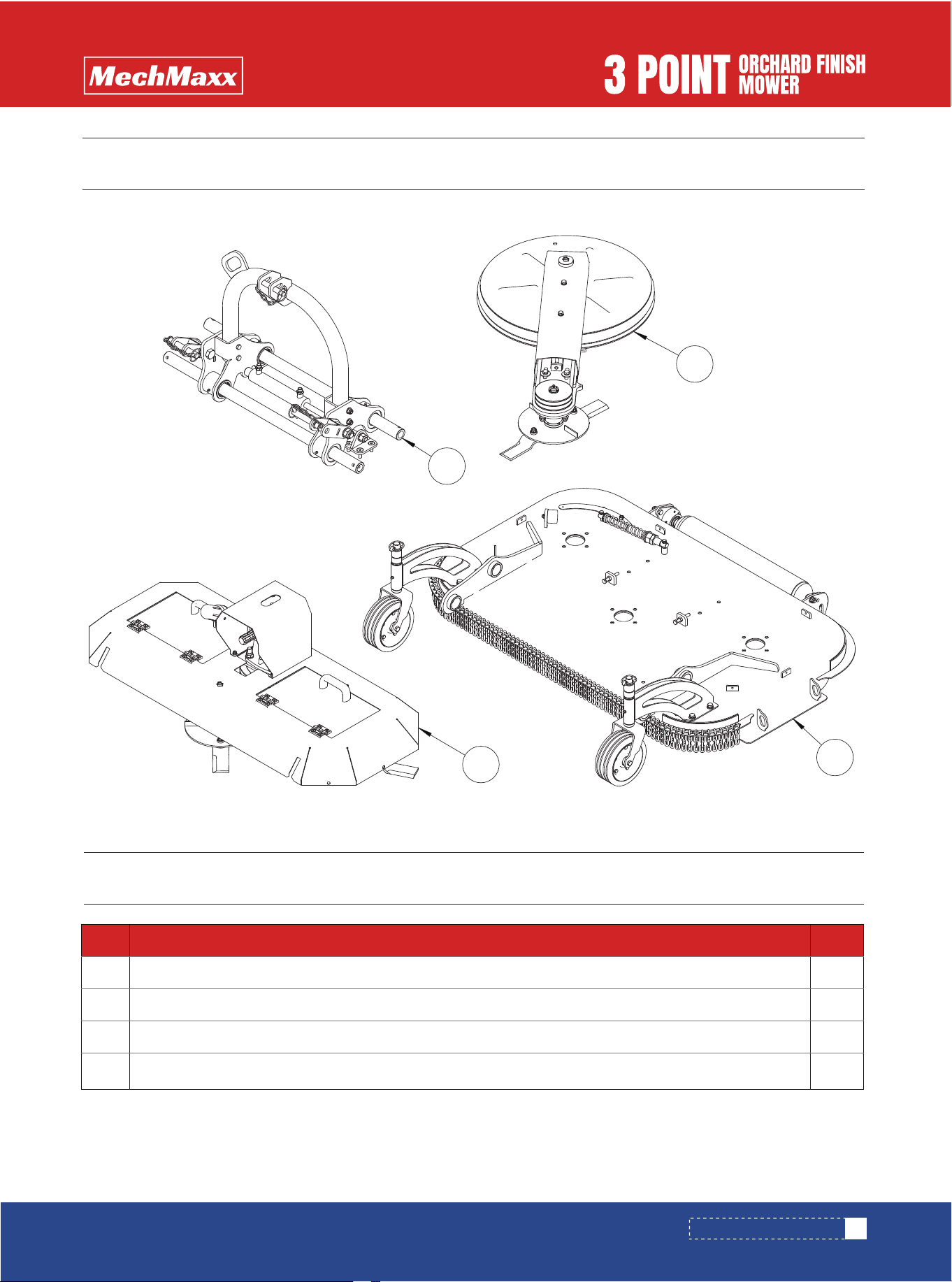
FMS60/72 PARTS LIST
1
1
1
1
No. DESCRIPTION Qty
1
2
3
4
3-Point Hitch Assembly
Mower Deck Assembly
Upper Belt Guard Assembly
Center Pulley Cover Assembly
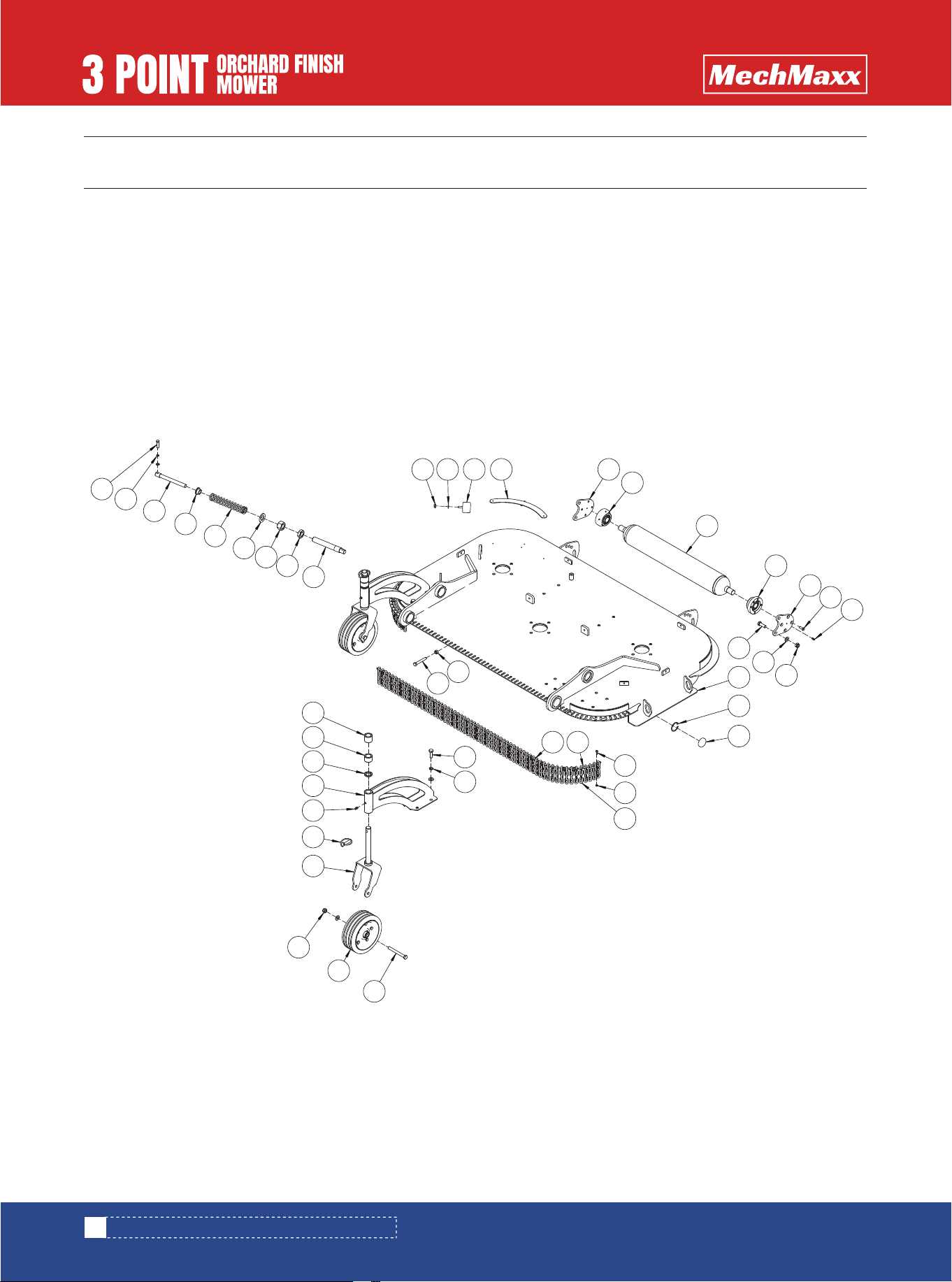
FMS60/72 PARTS DIAGRAM
FMS60/72 PARTS DIAGRAM
1
2
3
4
22
www.mechmaxx.com
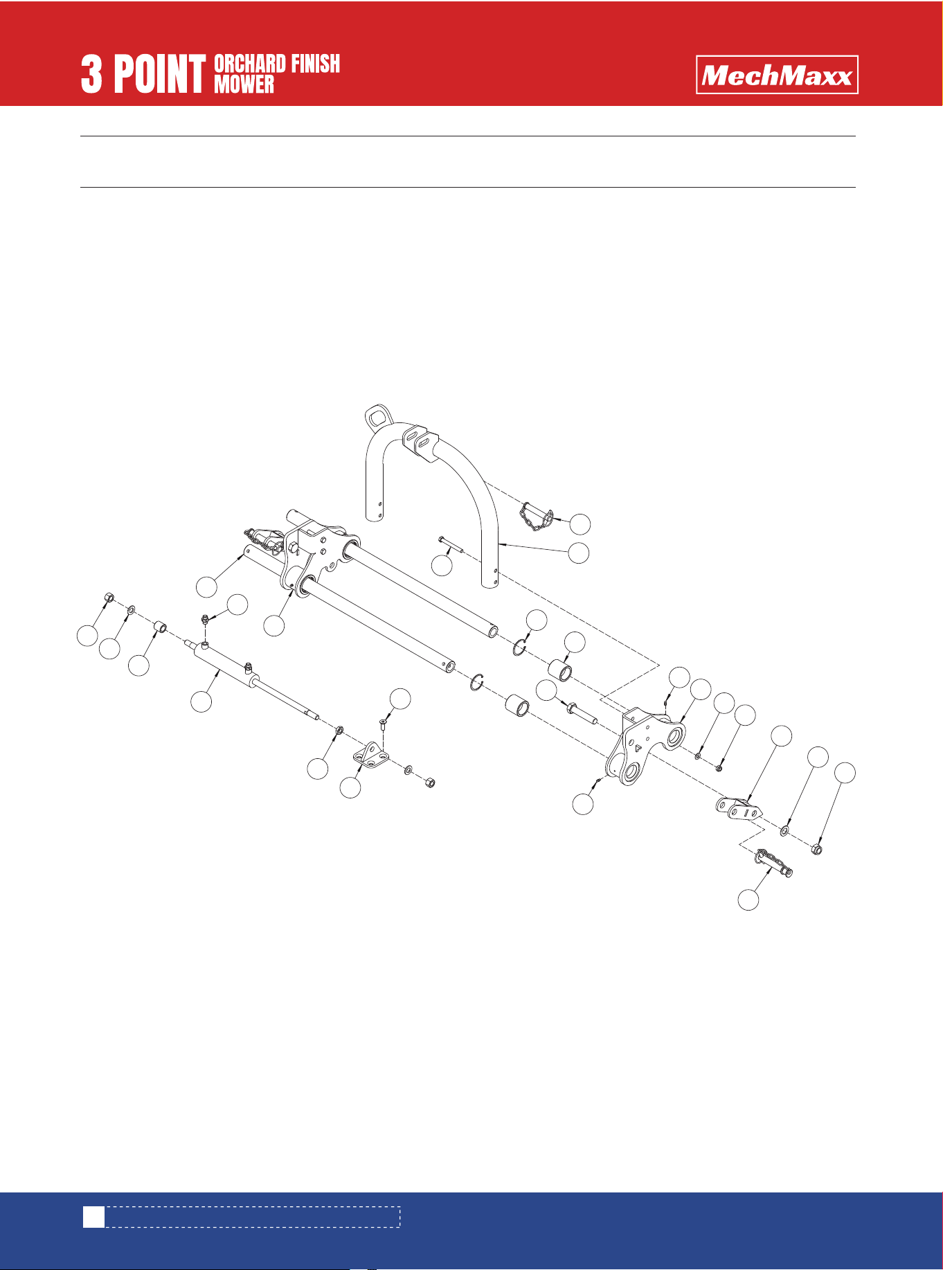
FMS60/72 PARTS DIAGRAM (3-POINT HITCH ASSEMBLY)
19
14
2
12
20
11
21
10
22
6
7
17
1
18
9
16
8
3
24
23
15
13
4
5
6
FMS60/72 PARTS DIAGRAM (3-POINT HITCH ASSEMBLY)

23
www.mechmaxx.com
FMS60/72 PARTS LIST (3-POINT HITCH ASSEMBLY)
FMS60/72 PARTS LIST (3-POINT HITCH ASSEMBLY)
1
1
4
4
4
4
1
4
4
2
2
2
2
2
4
1
2
2
2
2
2
2
1
1
1
1
1
1
No. DESCRIPTION Qty
1
2
3
4
5
6
7
8
9
10
11
12
13
14
15
16
17
18
19
20
21
22
23
24
Upper Hitch Pin
Hitch Bracket Weldment
Hex Bolt M12 × 100
Cotter Pin Ø6.0
Nylon Bushing
Grease Zerk M6
Left Hitch Bracket Weldment
Flat Washer M12
Lock Nut M12
Lower Hitch Bracket Weldment
Flat Washer M22
Lock Nut M22
Hex Bolt M22 × 110
Category I Lower Hitch Pin
Socket Head Cap Screw M12 × 35
Right Hitch Bracket Weldment
Hydraulic Adapter Fitting
Guide Rod
Lock Nut M18 × 1.5
Flat Washer M18
Spacer Sleeve
Hydraulic Cylinder Assembly
Thin Hex Nut M18 × 1.5
Hydraulic Cylinder Mount Weldment
120
150
180
120
150
180
Not used
on FMU120
Remarks
24
www.mechmaxx.com
FMS60/72 PARTS DIAGRAM (MOWER DECK ASSEMBLY)
FMS60/72 PARTS DIAGRAM (MOWER DECK ASSEMBLY)
5
22
9
3
1
2
6
8
10
7
11
13
4
12
26
28
30
29
24
10
25
27
23
1920
16
18
17
12
21
6
5
14
15
41
40
39
38
37
36
35
34
33
31
32

25
www.mechmaxx.com
FMS60/72 PARTS LIST (MOWER DECK ASSEMBLY)
FMS60/72 PARTS LIST (MOWER DECK ASSEMBLY)
1
3
1
1
2
2
1
1
1
8
2
6
14
12
1
1
1
4
4
10
10
53
77
89
4
4
4
1
1
120
150
180
120
150
180
120
150
180
120
150
180
120
150
No. DESCRIPTION Qty
1
2
3
4
5
6
7
8
9
10
11
12
13
14
15
16
17
18
19
20
Lock Nut M8
Flat Washer M8
Rubber Cushion Assembly
Belt Guide Plate
Roller Mounting Bracket
Flanged Bearing Unit UC205
Roller Weldment
Socket Head Cap Screw M8 × 25
Grease Zerk M6
Lock Nut M12
Flat Washer M12
Hex Bolt M12 × 35
Mower Deck Weldment
Cotter Pin Ø4.5
Roller End Cap Ø45
Hex Socket Screw M5 × 16
Lock Nut M5
Chain Kit (Ø6 × 15–35)
Left & Right Chain Hanger Brackets
Long Chain Hanger Bracket
Remarks

26
www.mechmaxx.com
FMS60/72 PARTS LIST (MOWER DECK ASSEMBLY)
1
8
2
2
2
2
2
2
2
2
2
2
2
1
1
1
1
1
1
1
2
2
180
No. DESCRIPTION Qty
21
22
23
24
25
26
27
28
29
30
31
32
33
34
35
36
37
38
39
40
41
Spring Washer M12
Hex Bolt M12 × 110
Roller Assembly
Caster Fork Weldment
Lock Pin Assembly – 12
Grease Zerk M8 × 1
Roller Frame Weldment
Short Adjustment Collar
Adjustment Collar A
Long Adjustment Collar
Hex Bolt M10 × 70
Hex Nut M10
Locking Rod
Thin Hex Nut M24
Hex Nut M24
Flat Washer M24
Compression Spring
Limit Sleeve
Inner Rod
Spring Washer M8
Hex Bolt M8 × 35
Remarks
27
www.mechmaxx.com
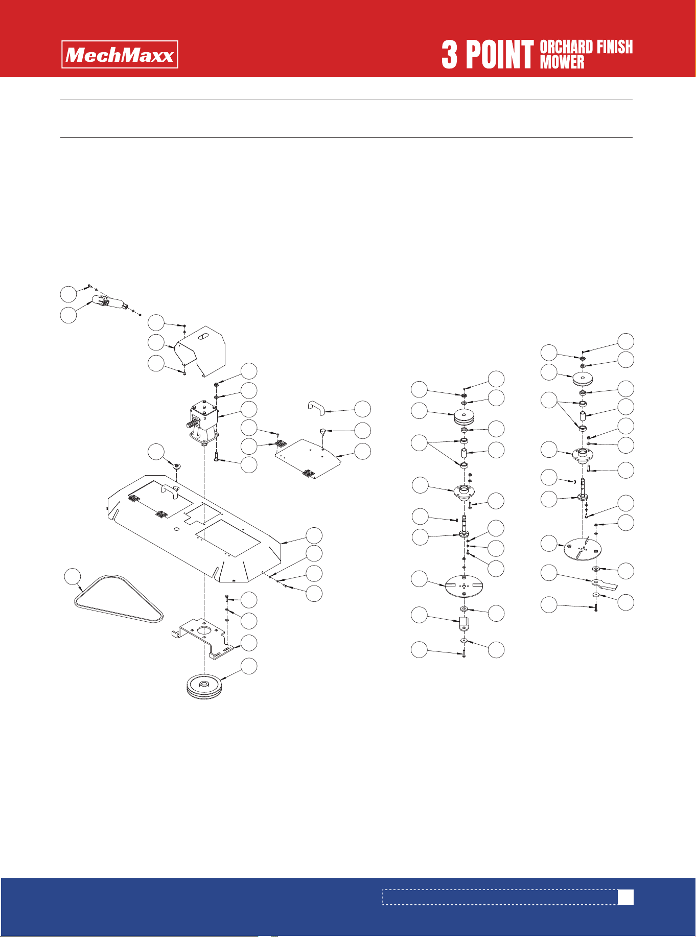
FMS60/72 PARTS DIAGRAM (UPPER BELT GUARD ASSEMBLY)
FMS60/72 PARTS DIAGRAM (UPPER BELT GUARD ASSEMBLY)
20
24
21
41
18
3
4
25
40
26
45
29
42
7
31
44
43
11
27
30
9
35
34
32
36
5
33
17
8
15
10
16
12
40
25
41
24
1
23
22
14
13
11
6
39
33
32
34
35
30
36
29
11
27
39
26
28
28
1
2
19
37
38

28
www.mechmaxx.com
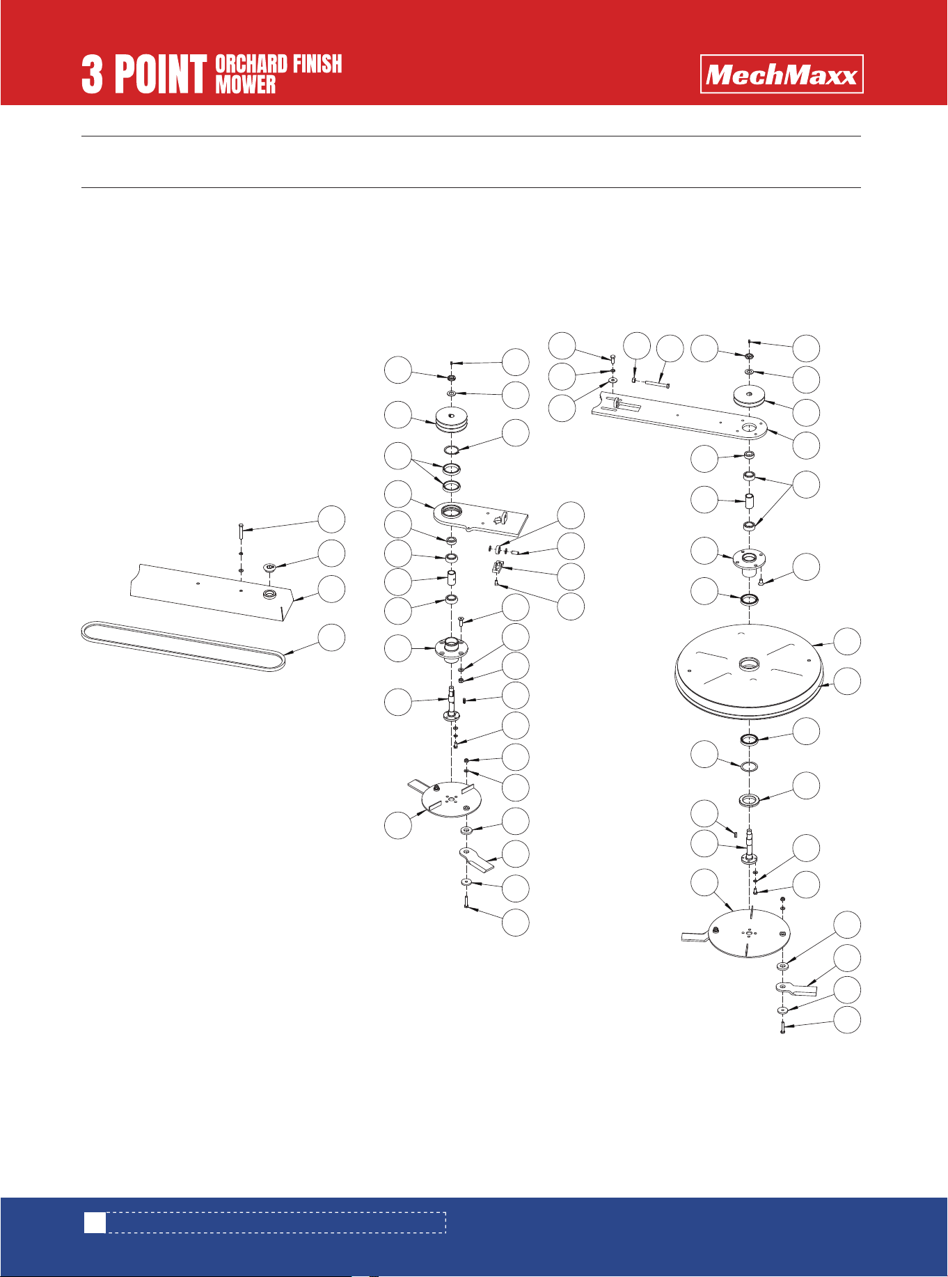
FMS60/72 PARTS LIST (UPPER BELT GUARD ASSEMBLY)
FMS60/72 PARTS LIST (UPPER BELT GUARD ASSEMBLY)
8
1
6
1
4
1
2
2
2
1
1
4
12
4
4
16
1
4
4
2
2
2
2
2
1
1
1
14
6
120
150
180
120
150
180
120
150
180
No. DESCRIPTION Qty
1
2
3
4
5
6
7
7
7
8
9
10
11
12
13
14
15
16
17
18
19
20
21
22
23
Hex Bolt M8 × 20
Operator’s Manual Tube (Small)
Lock Nut M8
Gearbox Cover
Hex Bolt M8 × 16
Rubber Protective Cap (40 Series)
V-Belt B1549
V-Belt B1753
V-Belt B1930
Double-Groove Large Pulley
Gearbox Mount
Spring Washer M12
Hex Bolt M12 × 40
Carriage Bolt M16 × 50
Hinge
Countersunk Socket Head Screw M8 × 16
Gearbox Assembly
Flat Washer M16
Lock Nut M16
Bakelite Handle Knob
Star Knob M10 × 25
Inspection Cover
Upper Belt Guard Weldment
Flat Washer M8
Spring Washer M8
Remarks

29
www.mechmaxx.com
FMS60/72 PARTS LIST (UPPER BELT GUARD ASSEMBLY)
4
4
2
2
2
2
2
2
4
1
2
2
2
2
2
12
8
8
4
4
1
8
12
4
120
150
180
No. DESCRIPTION Qty
24
25
26
27
28
29
30
31
32
33
34
35
36
37
38
39
40
41
42
43
44
45
Hex Bolt M10 × 50
Blade
Blade Carrier Weldment
Blade Shaft
Parallel Key A8 × 25
Blade Mount Weldment
Ball Bearing 6205
Double-Groove Small Pulley
Round Nut M20 × 1.5
Grease Zerk M6
Flat Washer M20
Short Spacer
Spacer Sleeve
Flat Washer M10
Spring Washer M10
Hex Bolt M10 × 20
Blade Spacer
Shim Washer
Single-Groove Pulley
Lock Nut M12
Flat Washer M12
Lock Nut M10
Remarks
30
www.mechmaxx.com
FMS60/72 PARTS DIAGRAM (CENTER PULLEY COVER ASSEMBLY)
FMS60/72 PARTS DIAGRAM (CENTER PULLEY COVER ASSEMBLY)
4
15
28
14
35
44
27
43
26
34
16
36
33
37
40
3
25
46
47
38
45
13
42
12
39
22
41
6
8
10
9
17
12
1
11
2
32
31
5
30
29
18
7
20
12
28
27
26
25
24
23
6
22
8
9
8
10
16
14
15
19
21
21

31
www.mechmaxx.com
FMS60/72 PARTS LIST (CENTER PULLEY COVER ASSEMBLY)
FMS60/72 PARTS LIST (CENTER PULLEY COVER ASSEMBLY)
2
1
1
1
1
1
1
2
1
4
2
2
1
4
1
2
2
2
1
4
6
4
2
8
4
14
4
4
4
120
150
180
No. DESCRIPTION Qty
1
2
3
4
5
6
7
8
9
10
11
12
13
14
15
16
17
18
19
20
21
22
23
24
25
26
27
Hex Bolt M10 × 70
Rubber Protective Cap (40 Series)
Swing Arm Guard Weldment
V-Belt B1930
Blade Carrier Weldment
Blade Shaft
Countersunk Blade Mount Weldment
Ball Bearing 6205
Spacer Sleeve
Short Spacer
Swing Arm Base Weldment
Ball Bearing 61812-2Z
Double-Groove Small Pulley
Round Nut M20 × 1.5
Grease Zerk M6
Flat Washer M20
Shaft Retaining Ring Ø60
Countersunk Socket Head Screw M12 × 40
Flat Washer M12
Lock Nut M12
Parallel Key A8 × 25
Hex Bolt M10 × 20
Lock Nut M10
Flat Washer M10
Blade Spacer
Blade
Shim Washer
Remarks

32
www.mechmaxx.com
FMS60/72 PARTS LIST (CENTER PULLEY COVER ASSEMBLY)
4
2
1
1
1
2
2
2
1
1
1
1
1
10
1
1
1
4
1
1
No. DESCRIPTION Qty
28
29
30
31
32
33
34
35
36
37
38
39
40
41
42
43
44
45
46
47
Hex Bolt M10 × 50
Socket Head Cap Screw M8 × 16
Guide Wheel Mount
Cylindrical Pin Ø12 × 30
Ball Bearing 6301-2Z
Heavy Flat Washer M12
Spring Washer M12
Hex Bolt M12 × 30
Hex Nut M12
Hex Bolt M12 × 100
Blade Mount UFO Weldment
Spacer Ring
Blade Carrier UFO Weldment
Spring Washer M10
Round Nut M60 × 2
Anti-Vibration Rubber Ring
Cover UFO Weldment
Countersunk Socket Head Screw M12 × 25
Swing Arm Weldment
Single-Groove Pulley
Remarks