REV05022024
25TON LOG SPLITTER
Instruction & Assembly
SAVE THESE INSTRUCTIONS FOR FUTURE REFERENCE
Customer Support (888) 680-2849 inquiry@bilthardusa.com

- 2 -
Table of Contents
G
eneral Warnings and Rules………………………………………………...3
Hazard Signal Word Definitions……………………………………………...4
Controls and Features Identification………………………………………...5
Component Parts……………………………………………………………...6
Assembly Instructions……………………………………...7, 8, 9, 10, 11, 12
Operation Instructions………………………………………….13, 14, 15, 16
Maintenance and Storage…………………………………………………..17
Troubleshooting………………………………………………………….......18
Specification………………………………………………………………….19
Parts Drawing & Parts List…………………………………………. 20, 21 22
- 3 -
GENERAL WARNINGS
READ and UNDERSTAND this manual completely before using 25 Ton Log Splitter.
Operator must read and understand all safety and warning information, operating instructions,
maintenance and storage instructions before operating this equipment. Failure to properly operate
and maintain the log splitter could result in serious injury to the operator or bystanders.
Operation Warnings
Do not carry passengers, sit or stand on the log splitter at any time.
Do not allow children to play on, stand upon or climb on the log splitter.
Always inspect the log splitter before using to assure it is in good working condition.
Replace or repair damaged or worn parts immediately.
Always check and tighten hardware and assembled parts before operation.
Do not exceed equipment maximum load capacity of 25 tons.
Avoid large holes and ditches when towing the equipment.
Always operate the log splitter on clear and level ground.
Do not operate the log splitter at night, only during daylight hours.
Always slow down when towing over rough terrain, streams, ditches and hillsides.
To avoid personal injury and/or equipment damage DO NOT EXCEED 45 MPH.
Always refer to the vehicle owner’s manual for proper towing.
Always secure and lock the log splitter to the vehicle hitch before towing.
Crush and Cut Hazards
Always keep hands and feet clear from moving parts while operating the equipment.
Always clear and keep work area clean and free of debris when operating.
Always
wear safety gear, eye protection, gloves and work boots when operating the log
splitter.
WARNING
The warnings, cautions, and instructions outlined in this instruction manual cannot cover all
possible conditions or situations that may occur. It must be understood by the operator that
common sense and caution are factors which cannot be built into this product and must be
supplied by the operator.
PROP 65 WARNING
This product can expose you to chemicals including lead and lead compounds which are
known to the State of
California to cause cancer and birth defects or other reproductive
harm. For more information, go to www.p65warnings.ca.gov
Assembly Is Required
This product requires assembly before use. See “Assembly” section for instructions. Because of
the weight and/or size of the log splitter, it is recommended that another adult be present to assist
with the assembly. INSPECT ALL COMPONENTS closely upon receipt to make sure no
components are missing or damaged.
- 4 -
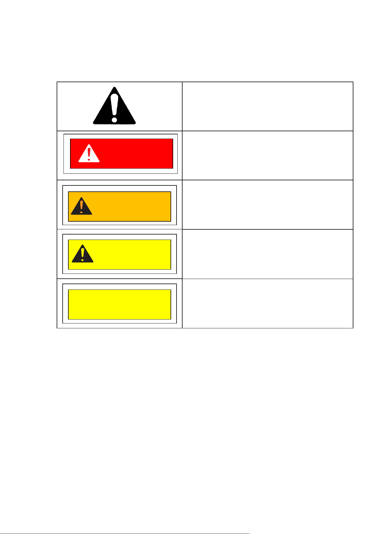
Hazard Signal Word Definitions
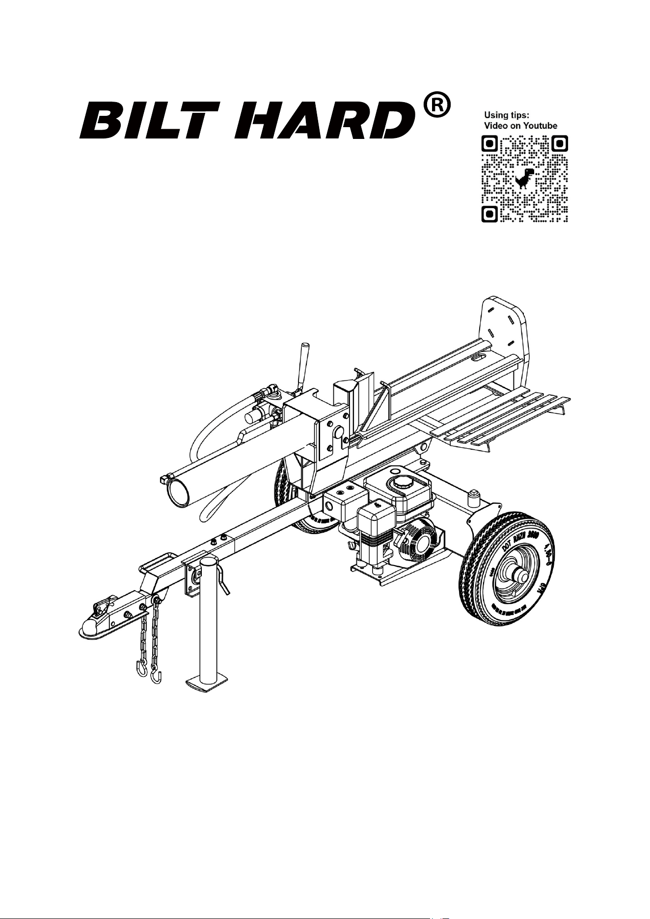
ABOUT YOUR 25 TON LOG SPLITTER
This hydraulic log splitter has a heavy-duty steel construction and 25 tons of ram force. When
there's work to be done, you need outdoor power equipment you can rely on, this log splitter will get
the job done fast. It is designed to work in both horizontal and vertical position. It is easy to tow,
easy to use and maintain. Never exceed the rated capacity of 25 tons when operating the log
splitter.
Technical specifications on the log splitter are provided in the “Specifications” section of this
manual.
CAUTION
CAUTION
WARNING
DANGER
CAUTION used without the safety alert symbol
indicates a potentially hazardous situation which,
if not avoided, may result in property damage.
This is the safety alert symbol. It is used to alert
you to potential personal injury hazards. Obey all
safety messages that follow this symbol to avoid
possible injury or death.
DANGER indicates an imminently hazardous
situation which, if not avoided, will result in death
or serious injury.
WARNING indicates a potentially hazardous
situation which, if not avoided, could result in
death or serious injury.
CAUTION indicates a potentially hazardous
situation which, if not avoided, may result in minor
or moderate injury.
- 5 -
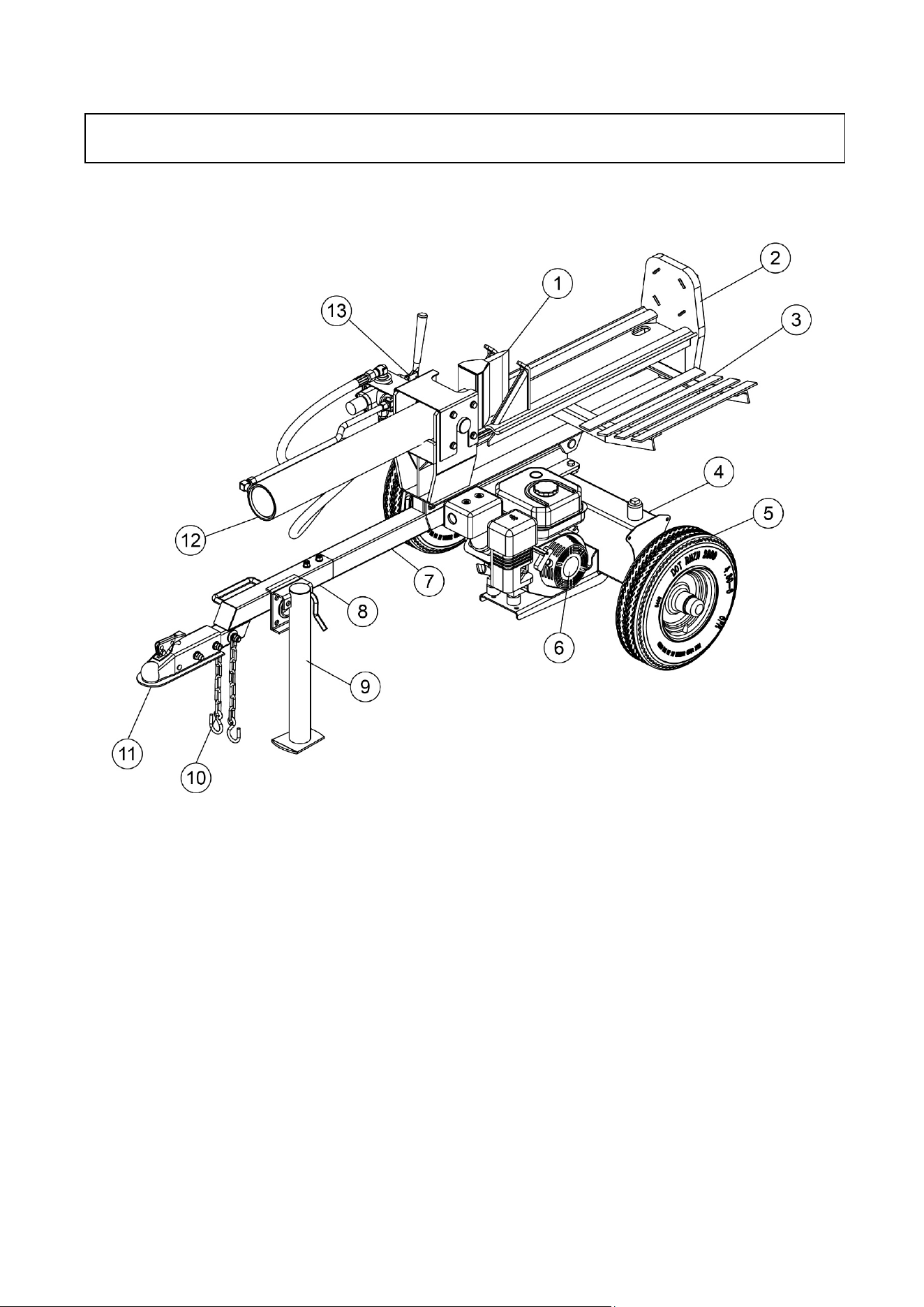
Read this owner’s manual before operating the equipment. Familiarize yourself with the location
and function of the controls and features. Save this manual for future reference.
1) 7” Wedge – Features wedge wings and tapered ends making splitting easier.
2) Beam – 8.5” wide.
3) Log Cradle
4) Hydraulic Reservoir
5) Tires – Maximum rated towing speed is 45 MPH.
6) Engine – Air cooled engine powers the hydraulic pump
7) Tow Bar A
8) Tow Bar B – Move with ATV & Lawn/Garden Tractor
9) Support Leg – Supports the log splitter while operating.
10) Safety Chains – Safety feature to prevent loss of log splitter while towing.
11) 2” Coupler – Attaches the log splitter to the 2” ball.
12) Hydraulic Cylinder – 4” bore and 23” stroke, rated to 3600 psi.
13) Control Valve Lever – Controls the forward and backward movement of splitting wedge.
Controls and Features Identification
- 6 -
25 TON LOG SPLITTER ASSEMBLY
Set the shipping crate on a solid flat surface and carefully remove the lid. Use two people and
take all parts out of the shipping crate and inspect the components to ensure there are no
missing pieces before starting to assemble the log splitter follow steps 1 through 12.
TOOLS REQUIRED
• Rubber or Wooden Hammer
• 13mm, 16mm, 17mm, 18mm, 19mm, 24mm, 27mm Wrenches
• Large Adjustable Wrench
• Phillips or Standard Screwdriver
• Pliers
WARNING
Read and follow all instructions for assembly and operation. Failure to properly assemble this
equipment could result in serious injury to the user or bystanders, or cause equipment damage
.
Engine Shipped Without Oil.
Before starting engine, fill with SAE 10W-30 motor oil.
See engine manual for engine oil capacity.
Hydraulic Reservoir is Shipped Without Oil.
When adding oil verify the oil level re
ads 1 from the top of hydraulic
reservoir if marking is not shown fill to the neck.
Inspect all Log Splitter Components.
If you have damaged components: Contact the freight company that
delivered the log splitter and file a claim.
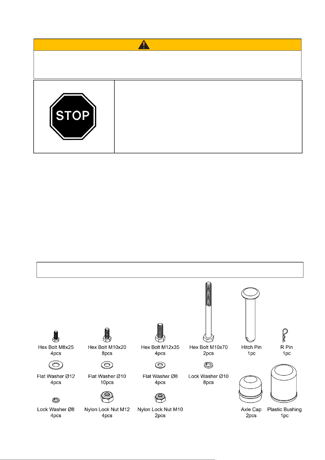
Component Parts
- 7 -
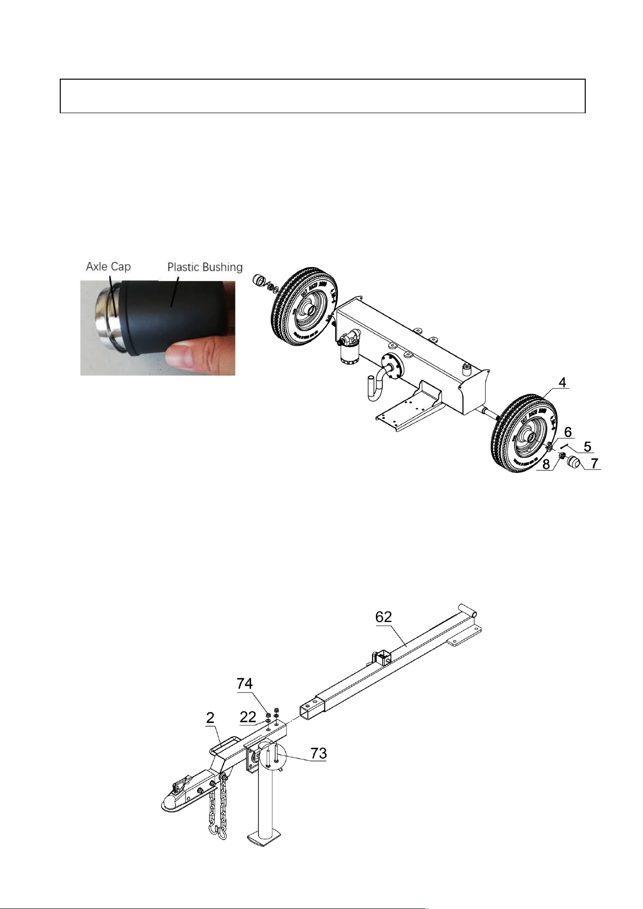
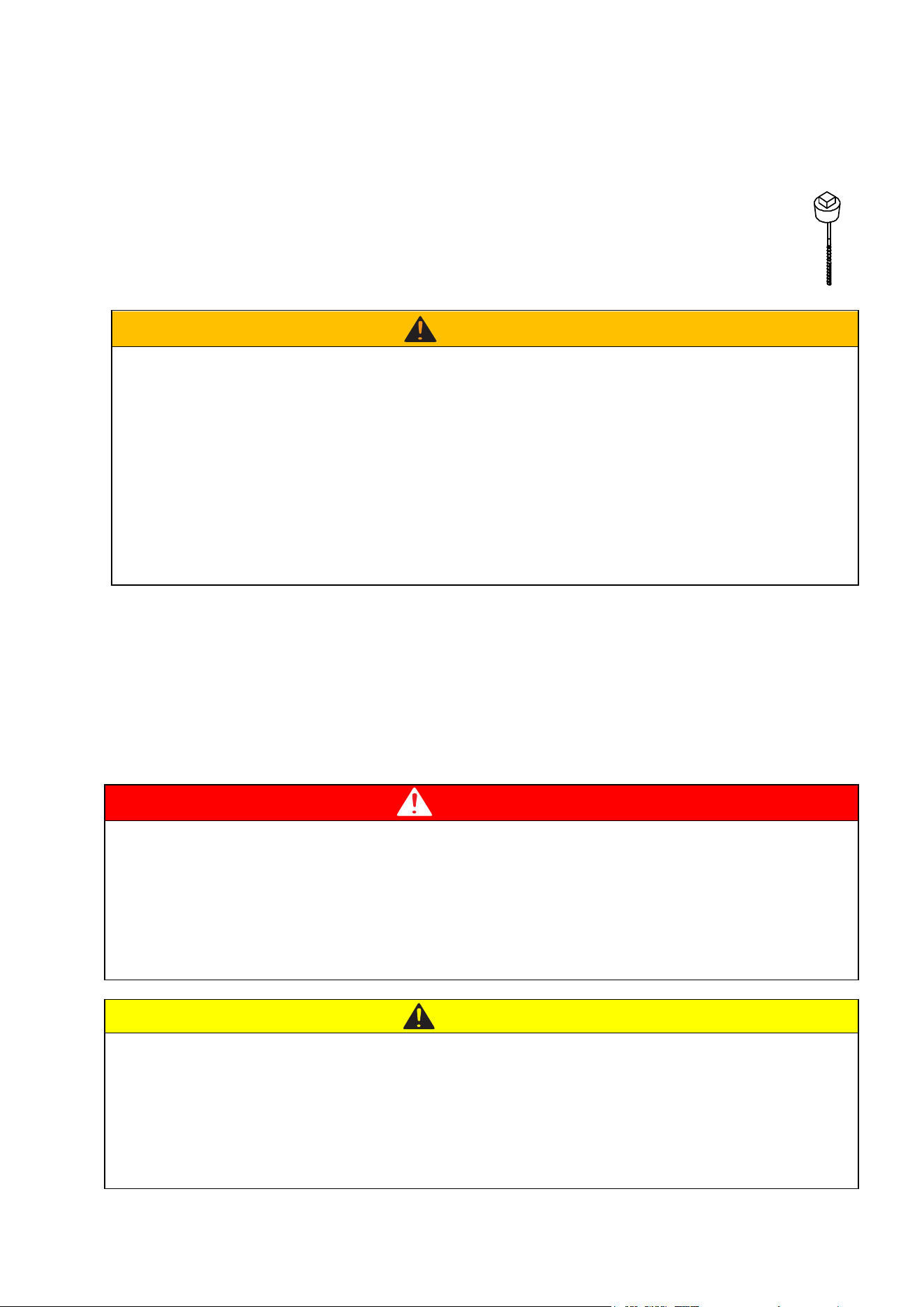
STEP 1: Wheel Assembly
1. Attach the wheels (#4) to the hydraulic reservoir axle secure using flat washer Ø20 (#6), thin
hex slotted nut M20 (#8) and cotter pin Ø4x36 (#5). Place plastic cover which in the blue bag
on the axle cap then install the axle cap (#7) on the end using rubber hammer.
NOTE: Use a black plastic bushing to fix the axle cap (#7) like below picture. Please cover the
black bushing onto the axle cap, and use rubber/wooden hammer knocking the end of the plastic
bushing and make the axle cap fixed on wheel.
STEP
2: Attach Tow Bar
1. Pull open the pin on the support leg, then lay down the support leg.
2. Attach the tow bar B (#2) to the tow bar A (#62) and secure using hex bolt M10x70 (#73), flat
washer Ø10 (#22) and nylon lock nut M10 (#74).
Assembly Instructions
WARNING: After tightening the slotted
nut, loosen nut 1/4 of a turn so the tire
will rotate freely. Failure to loosen the
nut may cause excessive bearing and
tire wear.
- 8 -
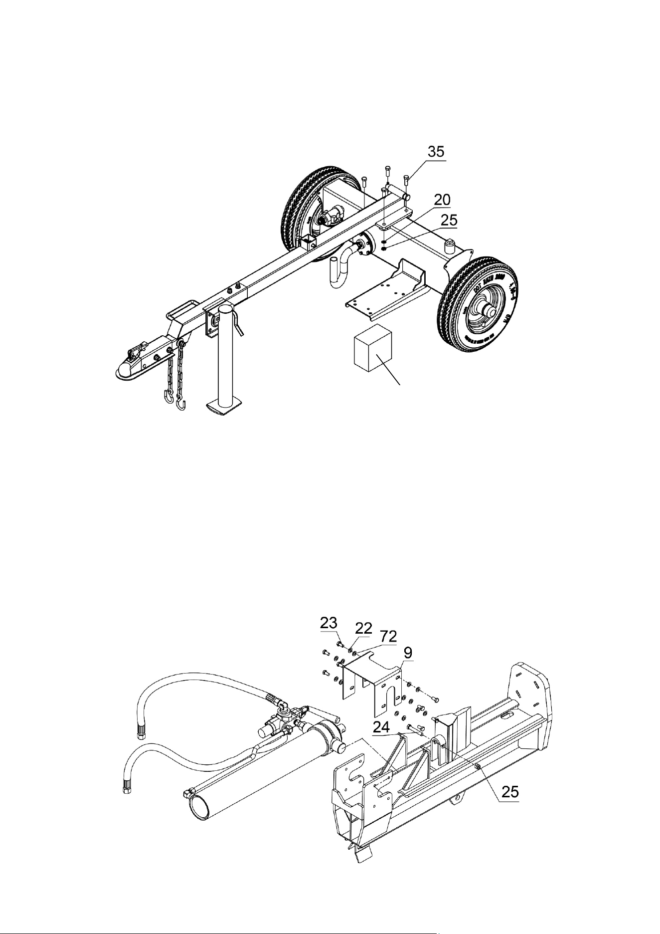
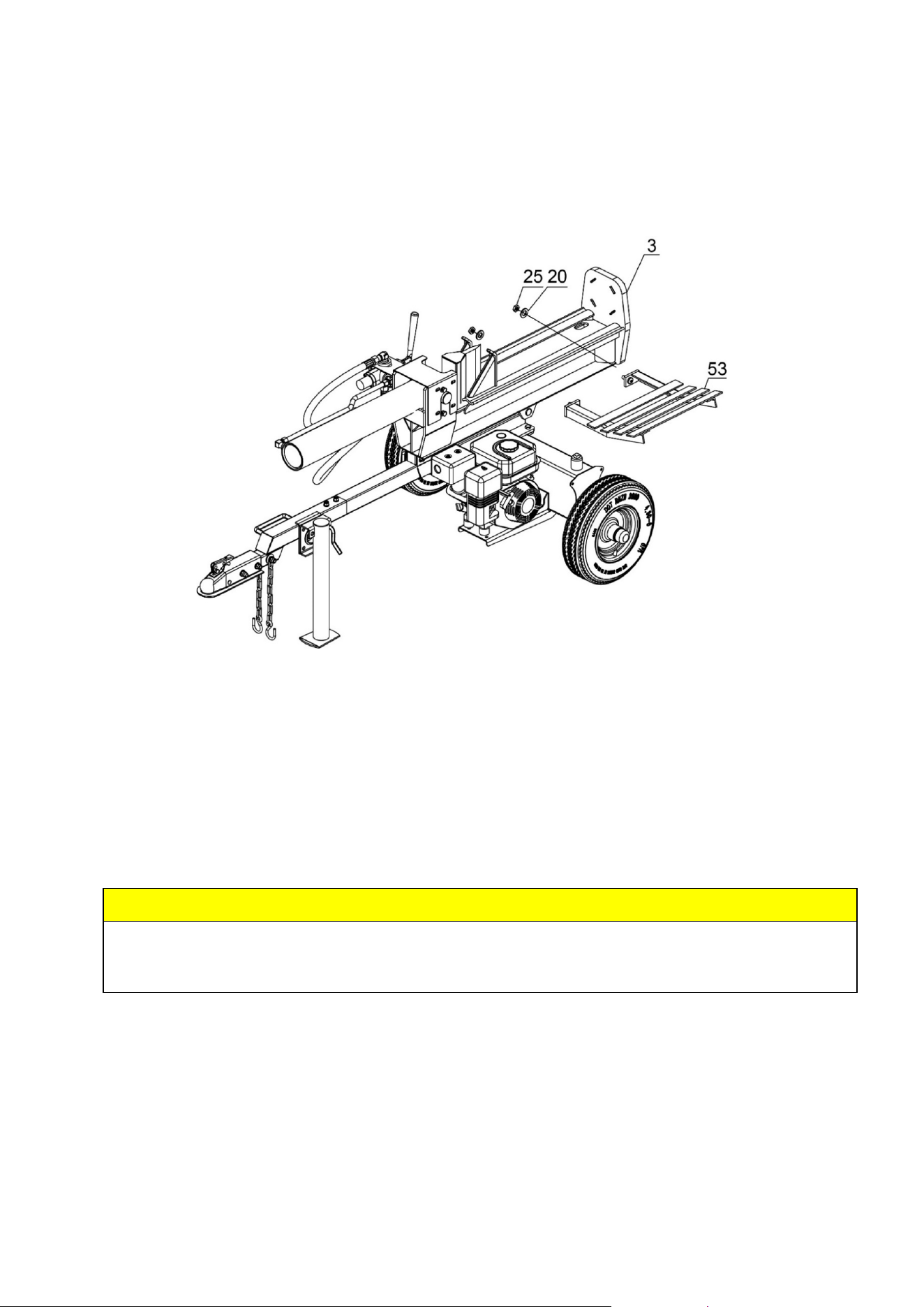
STEP 3: Attach Tow Bar to the Hydraulic Reservoir
1. Attach the tow bar to the hydraulic reservoir and secure using hex bolt M12x35 (#35), flat
washer Ø12 (#20) and lock nut M12 (#25).
STEP 4: Attach Cylinder and Wedge
1. Remove the cylinder and wedge assembly from carton, remove nylon lock nut M12 (#25) and
hex bolt M12x70 (#24) from the wedge, then install the wedge onto the beam rail from near
card slot.
2. Attach the cylinder to the card slot of beam, connect the cylinder cover (#9) using lock washer
Ø10 (#72), flat washer Ø10 (#22) and hex bolt M10x20 (#23). Then connect the wedge to the
piston rod of cylinder using hex bolt M12x70 (#24) and lock nut M12 (#25).
Attention: make sure the wedge is tied on the beam before wedge assembly connecting.
To prevent the reservoir from tipping over, please
bring a piece of wood and pad it under the engine
mounting plate, the height of the wood is 8.6 inches.
- 9 -
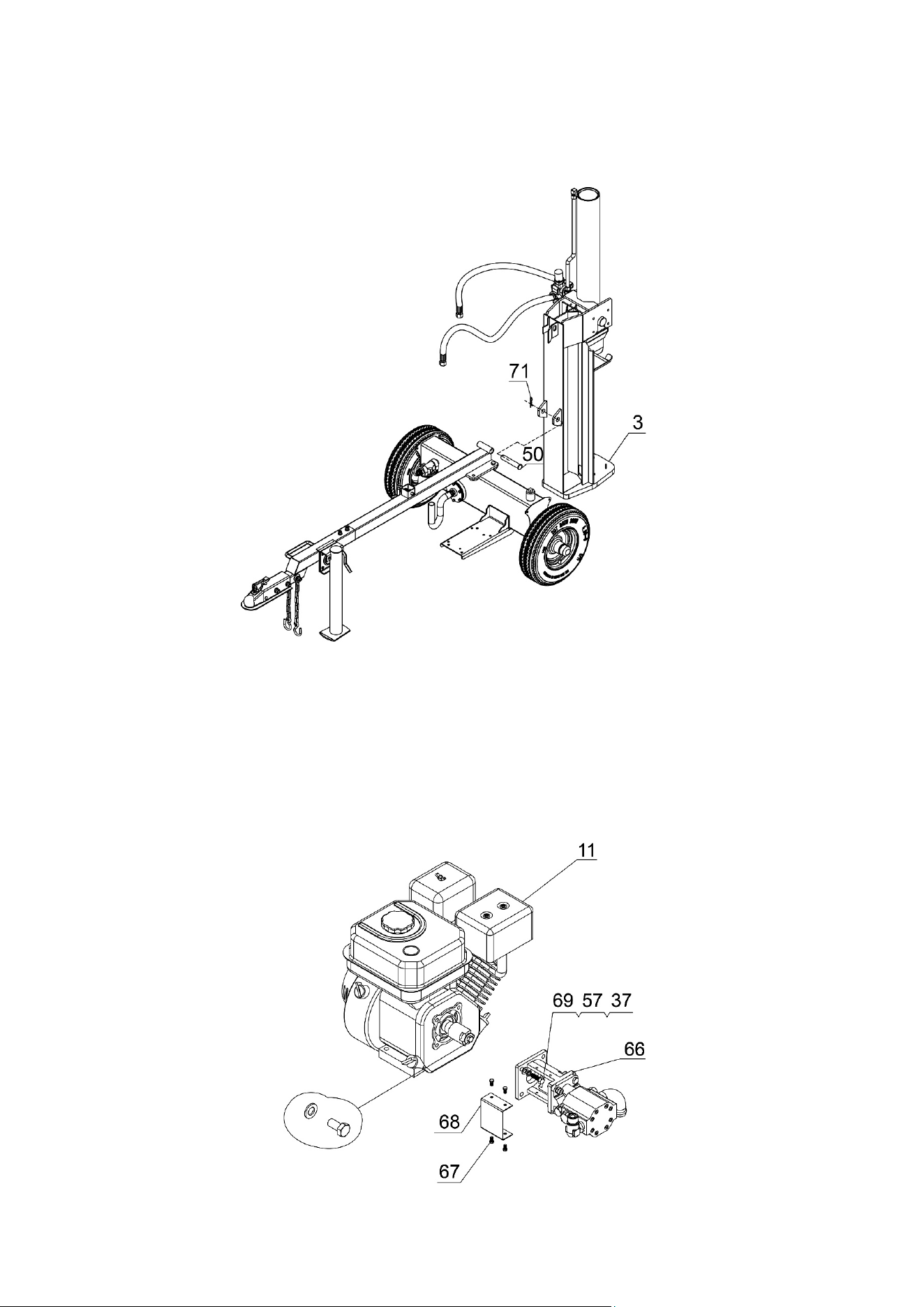
STEP 5: Attach the Beam Assembly
1. Attach the beam assembly (#3) to the tow bar and secure using hitch pin (#50) and R pin
(#71).
STEP 6: Attach the Gear Pump Stand
1. Remove the bolt and washer from the engine output end (do not install them again).
2. Remove the hex bolt M5x10 (#67), then remove the coupling cover (#68).
3. Attach the gear pump stand (#66) to the engine (#11) using Hex Bolt M8x25 (#69), lock
washer Ø8 (#57) and flat washer Ø8 (#37).
4. Attach the coupling cover (#68) to the gear pump stand (#66) using hex bolt M5x10 (#67).
- 10 -
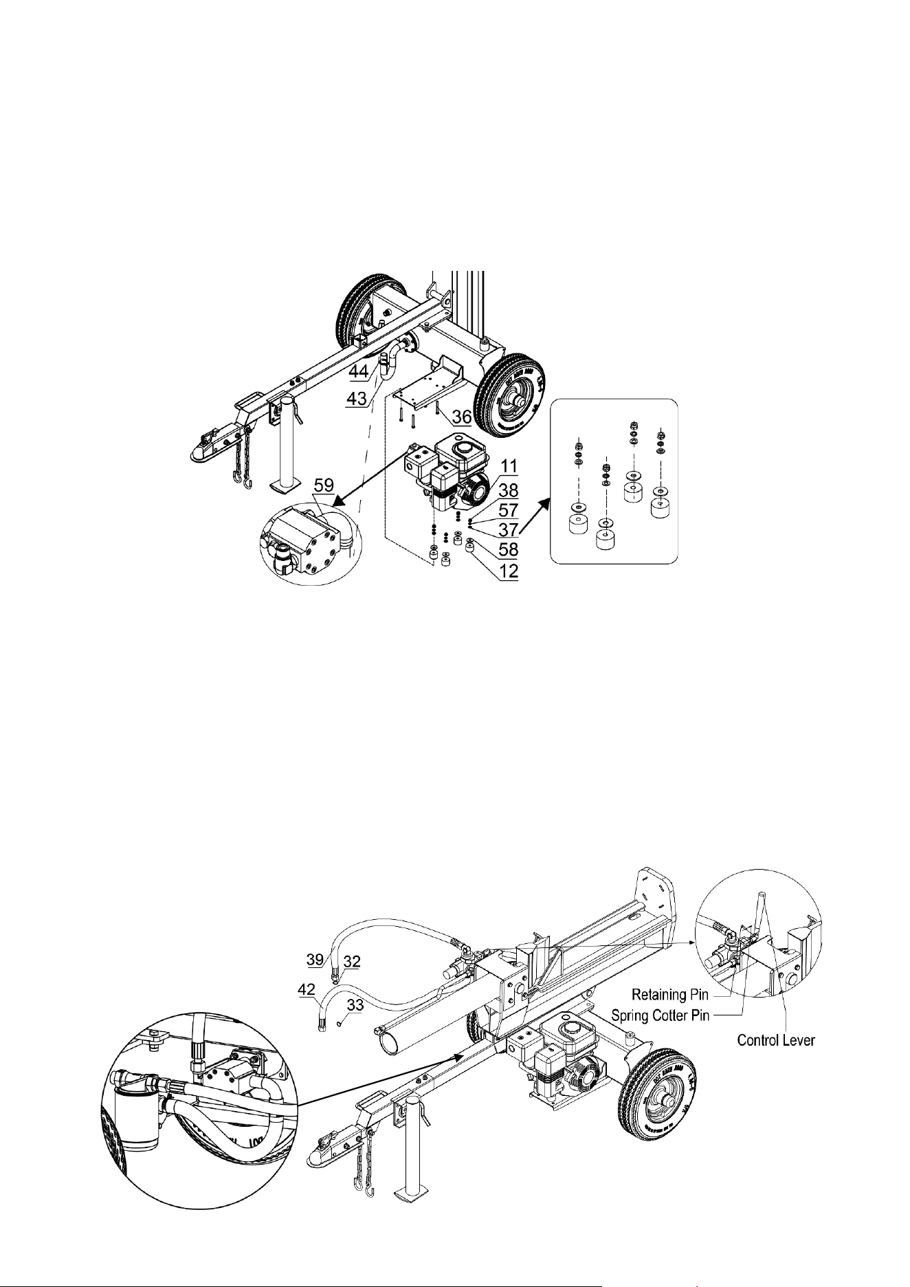
STEP 7: Attach Engine to the Mounting Plate
1. Place the four polyurethane blocks (#12) and large flat washers Ø10 (#58) between the
mounting plate and engine.
2. Position the engine (#11) on the mounting plate and secure using hex bolt M8x65 (#36), flat
washer Ø8 (#37), lock washer Ø8 (#57), nylon lock nut M8 (#38).
3. Attach the clear oil pipe (#43) to the inlet port of gear pump (#59), tighten with clamp (#44).
STEP 8: Attach the Hydraulic Hose and Control Lever
Attention: Remove the plastic plug and O ring in the hose first which are used for shipping
purpose. There will be some residual oil in the hose, it does not matter.
1. Attach the hydraulic hose (#39) to the oil outlet connector of gear pump, put in O ring Ø11x2.5
(#32).
2.
Attach hydraulic hose (#42) to connector of the outer oil filter, put in O ring Ø17x2.5 (#33).
Note: Tighten hydraulic hose connector between torque of 80-90N
·
m
3. Remove the spring cotter pin and the retaining pin from the control valve. Rotate the control
lever to the vertical position and secure with the retaining pin and the spring cotter pin.
- 11 -
STEP 9: Attach Log Cradle Weldment
1. Remove the nylon lock nut M12 (#25) and flat washer Ø12 (#20) from log cradle weldment.
Install the log cradle weldment (#53) to the beam (#3), using flat washer Ø12 (#20) and nylon
lock nut M12 (#25).
2. Tighten all hardware.
STEP 10: Add Engine Oil
1. Make sure the log splitter is on a level surface.
2. Remove oil fill cap/dipstick to add oil.
3. Refer to the separate owner’s engine manual for the amount needed of SAE10W-30 engine
oil; replace oil fill cap/dipstick.
4. Check engine oil level daily and add as needed.
NOTE: During the break-in period check the engine oil level often.
STEP 11: Add Hydraulic Oil
1. The log splitter needs to be cold on a flat level surface before adding the hydraulic oil.
2. Remove the oil cap from the hydraulic reservoir.
3. Add approximately 2.64 gallons of hydraulic oil, AW32, AW46 & universal hydraulic oil are all
acceptable types of fluid. Automatic transmission fluid should be used when operating
in temperatures below 32 degrees (all units are tested and have excess oil in the ram).
4. Check the hydraulic oil level.
CAUTION
DO NOT attempt to crank or start the engine before it has been properly filled with the
recommended type and amount of oil. Damage to the log splitter as a result of failure to follow
these instructions will void your warranty.
- 12 -
5. Start engine and use the control lever to extend and retract wedge several times to
remove air from the lines.
6. With the wedge retracted, check hydraulic oil level again and fill if necessary.
7. Do not thread in the dipstick when checking the hydraulic oil level. The hydraulic oil should
be checked when the machine is cold and level. The oil should be kept above the “COLD”
line. Never fill the oil level above the “HOT” line when the unit is cold. This will result in oil
being expelled through the vent on the dipstick.
WARNING
DO NOT remove the
hydraulic oil fill cap when the engine is running or hot. Hot oil can escape
causing severe burns. Always allow the log splitter to cool completely before removing the hydraulic
oil cap.
High fluid pressure and temperature
s are created in the hydraulic log splitters. Hydraulic fluid will
escape through
a pin-size hole opening and can puncture skin and cause severe blood poisoning.
Inspect hydraulic system regularly for possible leaks. Never check for leaks with your hand while
the system is pressurized. Seek medical attention immediately if injured by escaping fluid.
Make sure all fittings are tight and secure before applying pressure. Relieve system pressure before
servicing.
Make sure the hydraulic
hoses do not touch any hot surfaces or cutting areas.
Hoses need to be positioned were they are clear from the engine and cutting wedge. To avoid serious
bodily injury always inspect
the hoses before operating the log splitter.
STEP 12: Add Gasoline to the Engine
1. Use only clean, fresh, regular unleaded fuel with a minimum 87 octane rating.
2. DO NOT mix oil with fuel.
3. Remove the fuel cap, and slowly add fuel to the tank. DO NOT overfill, allow approximately ¼
inch of space for fuel expansion.
4. Screw on the fuel cap and wipe away any spilled fuel.
DANGER
Log splitter engine exhaust contains carbon monoxide, a colorless, odorless, poison gas. Breathing
carbon monoxide will cause nausea, dizziness, fainting or death. If you start to feel dizzy or weak, get
to fresh air immediately.
Operate log splitter outdoors only in a well-ventilated area.
DO NOT operate the log splitter inside any building, enclosure or compartment.
DO NOT allow exhaust fumes to enter a confined area through windows, doors, vents or other
openings.
DANGER CARBON MONOXIDE, using a log splitter indoors CAN KILL YOU IN MINUTES.
CAUTION
Fuel and fuel vapors are highly flammable and extremely explosive.
Fire or explosion can cause severe burns or death.
Unintentional startup can result in entanglement, traumatic amputation or laceration.
Only use regular unleaded gasoline with a minimum 87 octane rating.
DO NOT mix oil and gasoline together.
Fill tank approximately ¼” below the top of the tank to allow for fuel expansion.
DO NOT fill fuel tank indoors or when the engine is running or hot.
DO NOT light cigarettes or smoke when filling the fuel tank.

- 13 -
WARNING
Before operating or using the log splitter, review the instructions below and all safety information.
Failure to follow these instructions may result in property damage or injury to the operator or
bystanders.
WARNING
ALWAYS use the log splitter for its intended use.
ONLY use the log splitter to split wood logs, length wise with the grain.
NEVER modify, alter or change the log splitter in anyway, modifications will void the warranty.
NEVER attach a rope, cable or other device to the control lever on the log splitter.
ONLY operate the log splitter in daylight.
NEVER leave the log splitter unattended while the engine is running.
DO NOT change the splitting position with the engine running. Contact with the muffler can cause
serious burns.
ALWAYS make sure the beam is in the locked position.
DO NOT let the beam drop as it could crush fingers or cause damage to the log splitter.
NEVER operate or let anyone else operate, the log splitter while under the influence of alcohol, drugs, or
medication.
USING YOUR LOG SPLITTER
1. DO NOT carry passengers, sit or stand on the log splitter at any time.
2. Check the hydraulic oil level and visually inspect all hoses and attachments for problems.
3. Inspect the engine and make sure the engine oil level is correct.
4. Before towing the log splitter the tires need to be fully inflated.
TIRE WARNING
DO NOT over inflate tires. Serious injury can result if tires explode.
DO NOT tow the log splitter if the tires are worn or will not hold air.
DO NOT exceed the maximum 45 MPH towing speed.
Operation Instructions
- 14 -
5. Refer to the vehicle owner’s manual for proper safety and towing instructions.
Installation Instructions
TOWING WARNING
Serious injury or death can occur if towing safety rules are not followed.
Always use chains, secure and lock the log splitter to the vehicle hitch before moving.
Drive safely. Be aware of the added length of the log splitter.
Never exceed the maximum travel speed of 45 mph.
Never ride or transport cargo on the log splitter.
Turn off the vehicle before leaving the log splitter unattended.
Block the log splitter wheels to prevent unintended movement
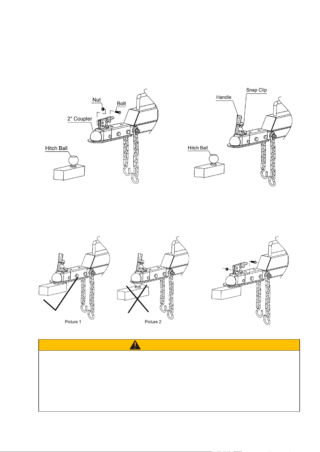
1. Remove the bolt and nut from the 2”
coupler.
2. Flip up the snap clip and handle of the
coupler.
3. Put the coupler on the hitch ball, need to
put it all in. Picture 1 is correct, while
Picture 2 is incorrect as it was not
installed in place.
4. Press down the handle of the coupler,
check whether the coupler is in place, then
reinstall the bolt and nut. Attach the chain
hook to the tractor.
- 15 -
6. The log splitter must have at least seven feet of clearance from combustible material. It
needs to be on a dry and level surface with good footing. Do not work on mud, ice, brush or
snow. When using the log splitter the work zone must be maintained at all times.
NOTE: Serious accidents can happen when other people are allowed inside the work zone.
Keep everyone else outside the work zone while operating the control lever.
7. Always wear safety gear, eye protection, gloves and work boots when operating the log
splitter
8. Start the engine and make sure the log splitter is on level ground before operating.
NOTE: The hydraulic oil needs to be above 10°F (-12C°) before starting the engine. Cold
hydraulic oil can damage the hydraulic pump. If outdoor air temperature is below 32°F (0C°)
allow the log splitter to warm up by extending and returning the wedge several times
before splitting wood.
9. Put both support legs in the down position to prevent the log splitter from moving during
operation and block both tires.
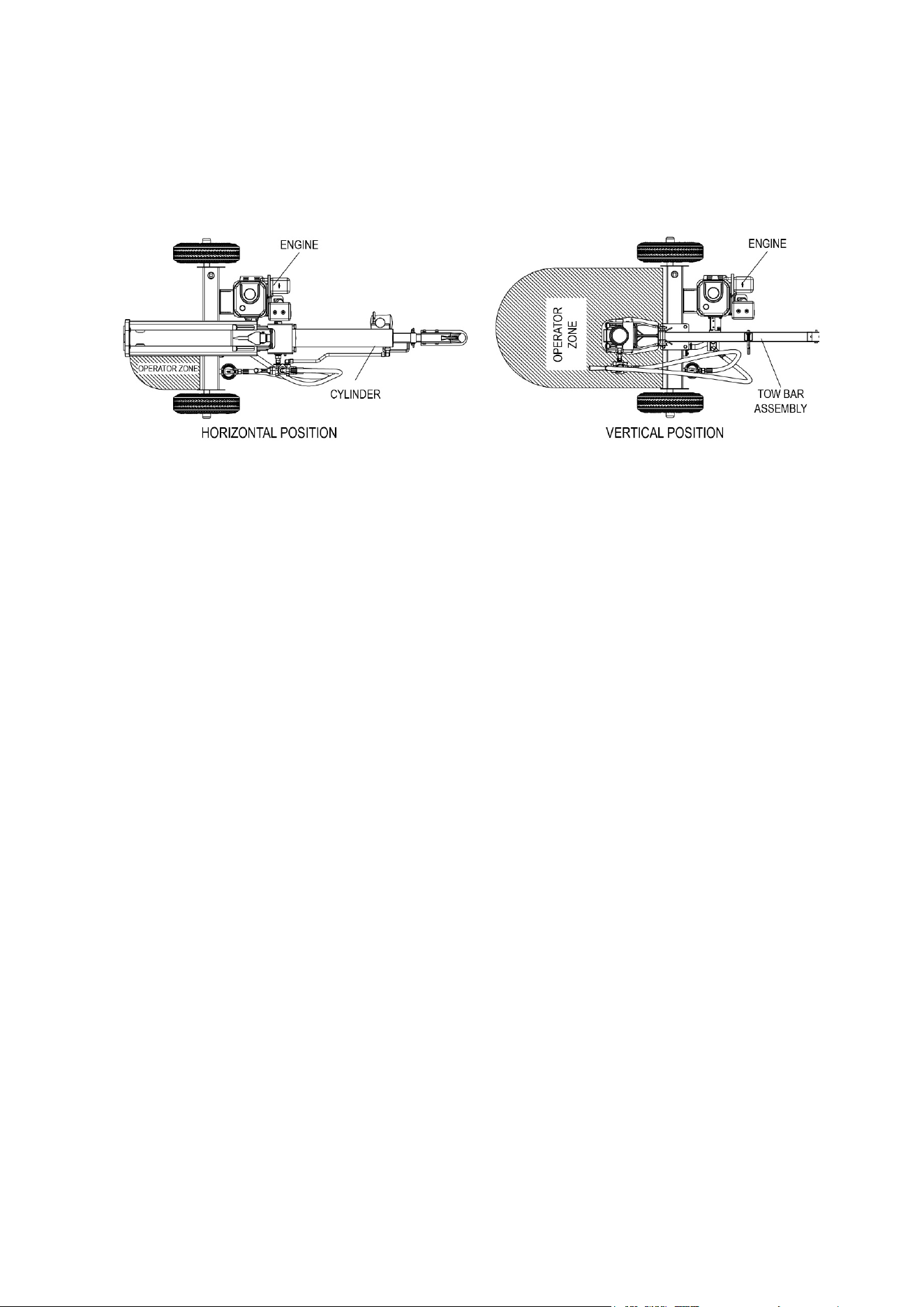
10. Set the log splitter in horizontal position.
NOTE: HORIZONTAL position is used for lighter logs that can easily be loaded onto the
beam. Back injury can result from lifting logs onto the log splitter if proper lifting
techniques are not used.
- 16 -
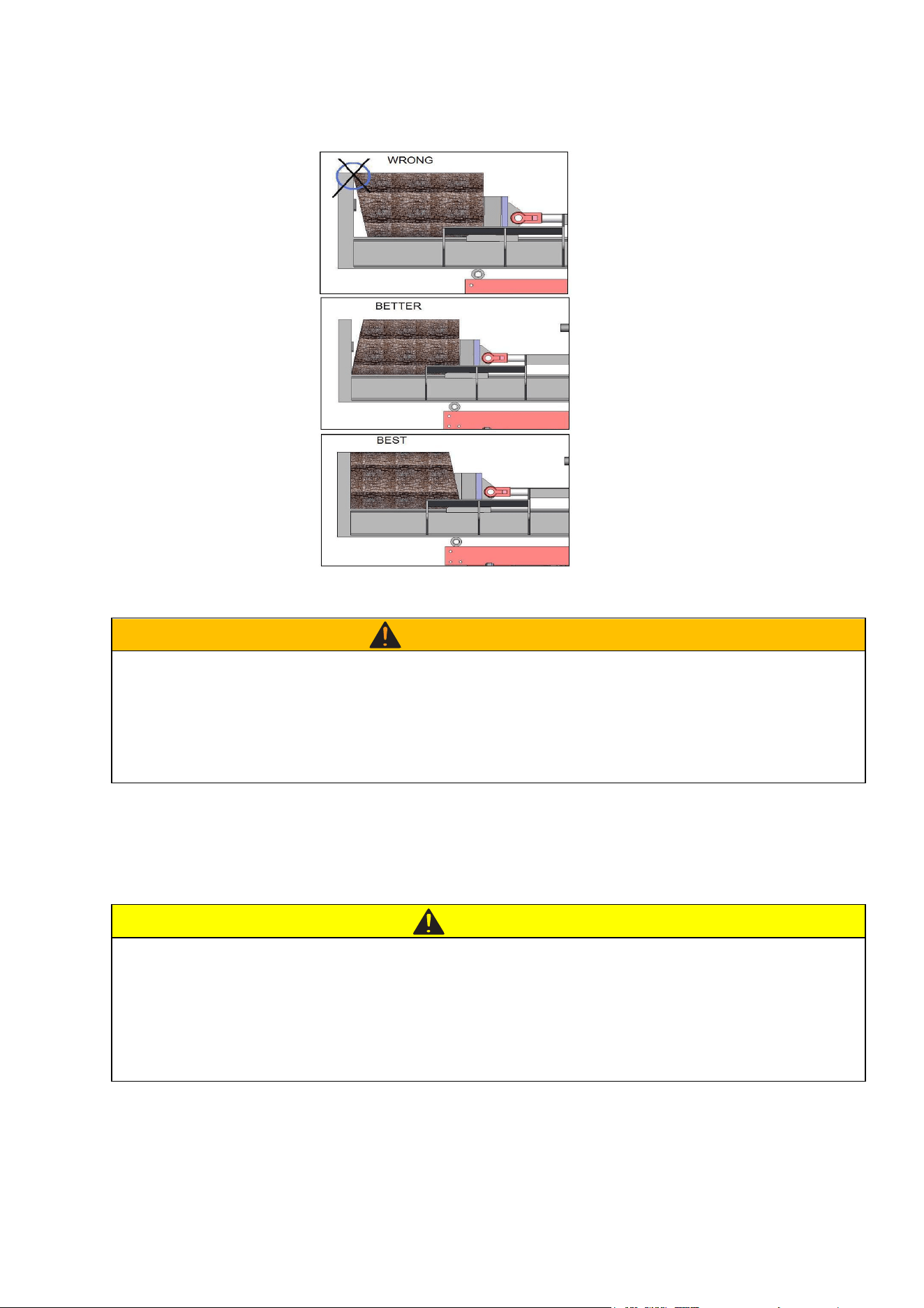
11. Load a log onto the beam against the endplate (Max Log Length-24”)
12. Make sure hands are clear from the wedge and crush hazard areas.
CRUSH WARNING
Wedge can cut through skin and break bones. Keep both hands away from wedge and beam slide.
Serious accidents can happen when other people are allowed inside the work zone. Keep everyone
else out of the work zone while operating control lever.
DONOT wear loose clothing. It can get tangled in moving parts of log splitter.
Only use the log splitter in daylight so you can see what you are doing.
13. Push control lever FORWARD by one hand to split the log.
14. Push control lever BACKWARD by one hand to return wedge to its original position
CAUTION
If a log gets stuck, embedded or will not split completely, push the control lever in the reverse direction
and allow the splitter to strip the log from the wedge.
If the log still remains stuck, embedded or will not split, turn the machine off and use a sledge hammer
and crow bar to remove the log.
ALWAYS keep hands clear of the log and wedge while it is retracting.
15. Always keep work zone clean and free of split wood and debris.

- 17 -
CAUTION
Improper maintenance and storage of the log splitter may void your warranty.
MAINTENANCE
• Before performing maintenance, the log splitter must be placed in maintenance mode.
Turn off the engine and move the control lever forward and backwards to relieve the
hydraulic pressure.
• After performing any maintenance, make sure all guards, shields and safety features are
put back in place before operating the log splitter.
• Before operating make sure the tires have the RECOMMENDED TIRE PRESSURE.
•
Regularly grease axle and wheel bearing area or when needed.
• After the wheel bearings have been greased make sure the axle nuts and pins are in place
and secure.
• Periodically check all fasteners and hoses for tightness and leaks.
• Annually clean and lightly lubricate all moving parts o
r when needed.
• Use a glossy enamel spray paint to touch up scratched or worn painted metal surfaces.
• Never exceed load capacity rating of 25 tons it will damage the log splitter.
What
When
How
Hoses
Each Use
Inspect hoses for exposed wire mesh and leaks.
Replace all worn or damaged hoses before
starting the engine.
Hydraulic Fittings
Each Use
Inspect fittings for cracks and leaks. Replace all
damaged fittings before starting the engine.
Nuts and Bolts
Each Use
Check for loose bolts, tighten before operating.
Beam
Each Use
Apply grease to beam surface.
Moving Parts
Each Use
Clear debris from log splitter.
Refer to the Engine Owner’s Manual for engine maintenance.
IMPORTANT:
If a part needs replacement, only use parts that meet the manufacturer’s specifications.
Replacement parts that do not meet specifications may result in a safety hazard or poor
operations.
STORAGE
• Before storing make sure the log splitter is clean and dry for years of trouble-free service.
• Lightly lubricate all log splitter surfaces and moving parts to prevent rust.
• Store indoors or protected area during severe weather and winter months.
Maintenance and Storage

- 18 -
Problem
Cylinder rod will not move
SOLUTION: A, D
Slow cylinder rod speed when
extending or retracting
SOLUTION: A, B, D, I
Wood will not split or splits extremely
slowly
SOLUTION: A, B, D, G, I
Valve will not stay in detent or will not
kick out of detent position
SOLUTION: H
Engine stalls under low load condition
SOLUTION: L
Engine will not start
SOLUTION: C, E, F, M
Engine is difficult to turn over and will
not start when cold
SOLUTION: J, M
Engine runs but cylinder does not move
SOLUTION: D, K
Cause
Solution
A-Insufficient oil to pump
Check oil level in reservoir
B-Air in oil
Check oil level in reservoir
C-Low engine oil
Check and add engine oil
D-Blocked hydraulic lines
Check for restriction
E-“ON”/“OFF”
Move to “ON” position
F-Fuel shut off in “OFF” position
Move to “ON” position
G-Damaged control valve Return control valve for authorized repair
H-Detent setting incorrect
Remove plastic cap on valve and adjust
detent kick out pressure
I-Internally damaged cylinder
Return cylinder for authorized repair
J-Cold ambient temperature Cold weather (below 32°) can result in
difficult engine starting. Change to ATF.
K-Broken pump / Engine coupler
Check and replace coupler
L-Defective pump or engine
Contact service center
M-Log splitter valve in the return
position
Push the control valve handle into the
middle (neutral) position.
Troubleshooting

- 19 -
Ram Force……………………………………………………………… 25 To n
Cycle Time………………………………………………………………13 Sec
(Note: Cycle time may vary given mechanical and environmental factors;
the published cycle time is for ideal conditions)
Wedge Size…………………………………………………. 7” Harden Steel
Gear Pump……………………………………………………………. 2-Stage
Hydraulic Oil……………………….AW32, AW46 & Universal Hydraulic Oil
Amount of Hydraulic Fluid…………………………………………..6 Gallon
Max. Log Length…………………………………………………………… 24”
Hydraulic Cylinder……………………………………………………. 4” x 23”
Max. Pressure………………………………………………………. 3600 PSI
Max. Flow……………………………………………………………..11GPM
Wheel Size………….... 4.8-8 wheel with 16” outside diameter D.O.T tires
Hitch Type…………………………………………………….. 2” Ball Coupler
Max. Towing Speed………………………………………………….. 45 MPH
Manual Start Engine…………………………………………………… 209cc
NOTE: For Engine Details Refer to the Engine Owner’s Manual.
Specifications
- 20 -
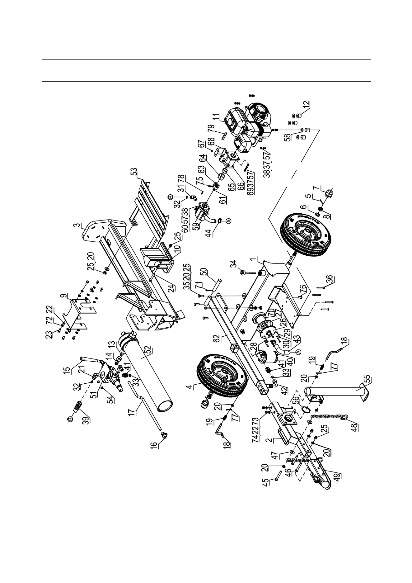
Parts Drawing & Parts List

- 21 -
Ref# Drawing No. Description Qty
1 LSM22A-02000
Hydraulic Reservoir
1
2 LSM22A-05000 Tow Bar B 1
3 LSM22A-01000 Beam 1
4 LSP25-14000
Wheel
2
5 9404-04035-DX
Cotter Pin Ø4x35
2
6 9301-20000-DX
Flat Washer Ø20
2
7 LSP25-00009-DG
Axle Cap
2
8 LSP25-00020-DX
Hex Slotted Thin Nut M20
2
9 LSM22A-00001 Cylinder Cover 1
10 LSM22A-04000 Wedge 1
11 LSP25-10001 Engine 1
12 LSP25-00025 Polyurethane Block 4
13 9901-16*2.5 O Ring Ø16x2.5 1
14 LSP25-17000 Combination Connector 1
15 LSM30-05000 Single Handle Control Valve 1
16 LSP25-06000 Cutting Sleeve Connector 2
17 LSM30-00004-DX Metal Hydraulic Hose 1
18 LSP25-00008-DX Lock Pin 2
19 LSP25-00003-DX Spring 2
20 9301-12000-DX
Flat Washer Ø12
12
21 LSP25-00019-DX Right Angle Connector 1
22 9301-10000-DX
Flat Washer Ø10
10
23 9101-10020-DX Hex Bolt M10x20 8
24 9101-12070-DX8.8 Hex Bolt M12x70 1
25 9206-12000-DX Nylon Lock Nut M12 10
26 LSP25-15000-DX
Filter Fix Plate
1
27 LSP25-00021
Rubber Washer
1
28 9301-06000-DX
Flat Washer Ø6
6
29 9306-06000-DX
Lock Washer Ø6
6
30 9101-06020-DX8.8 Hex Bolt M6x20 6
31 DS18-00008-DX Gear Pump Joint 1
32 9901-11*2.5 O Ring Ø11x2.5 2
33 9901-17*2.5 O Ring Ø17x2.5 2
34 LSP25-13000
Oil Bolt
1
35 9101-12035-DX8.8 Hex Bolt M12x35 4
36 9101-08065-DX8.8 Hex Bolt M8x65 4
37 9101-08000-DX
Flat Washer Ø8
8
38 9206-08000-DX Nylon Lock Nut M8 8
39 LSP25-00016 Hydraulic Hose (gear pump-valve) 1
40 LSP25-09000 Outer Oil Filter 1

- 22 -
Ref# Drawing No. Description Qty
41 LSP25-00007-DX Connector 2
42 LSP25-00017 Hydraulic Hose (valve-external filter) 1
43 LSP25-00018 Oil Pipe 1
44 LSP25-00011 Clamp 2
45 9101-12090-DX8.8 Hex Bolt M12x90 1
46 9101-12080-DX8.8 Hex Bolt M12x80 2
47 LSP25-00015-DX Thick Washer 2
48
LSP25-11000-DX
Chain
2
49 Z103
2” Coupler
1
50 LSP25-05000 Hitch Pin 1
51 LSM30-00005 Control Valve Cover 1
52 LSM22-04000 Cylinder 1
53 LSP25-00010 Log Cradle Weldment 1
54 9110-08010-DX Screw M8x10 2
55 LSM22A-06000 Front Support Leg 1
56 9304-62000-FH Steel Wire Snap Ring for Shaft B 1
57 9306-08000-DX Lock Washer Ø8 12
58
9302-10000-DX
Large Flat Washer Ø10
4
59 LSM22A-07000 Gear Pump 1
60 9101-08030-DX8.8 Hex Bolt M8x30 4
61 LSP25-10008-FH Wire Snap Rings for Shaft 1
62 LSM22A-03000 Tow Bar A 1
63 LSP25-10003 Gear Pump Coupler 1
64 LSP25-10002 Engine Coupler 1
65 LSP25-10004-DX Engine Bushing 1
66 LSP25-10005 Gear Pump Stand 1
67 9101-05010-DX8.8 Hex Bolt M5x10 4
68
LSP25-10006
Coupler Cover
1
69 9101-08025-DX8.8 Hex Bolt M8x25 4
70 LSP25-00022 Inner Oil Filter 1
71 LSP25-00012-DX R Pin 1
72 9306-10000-DX Lock Washer Ø10 8
73 9101-10070-DX8.8 Hex Bolt M10x70 2
74 9206-10000-DX Nylon Lock Nut M10 2
75 9121-06010-FH Screw M6x10 1
76 LSP25-00010
Oil Plug 3/8
1
77 9404-03030-DX
Cotter Pin Ø3x30
2
78
8801-3.2*3.2*25
Gear Pump Flat Key
1
79 8801-4.78*4.78*42 Engine Flat Key 1
