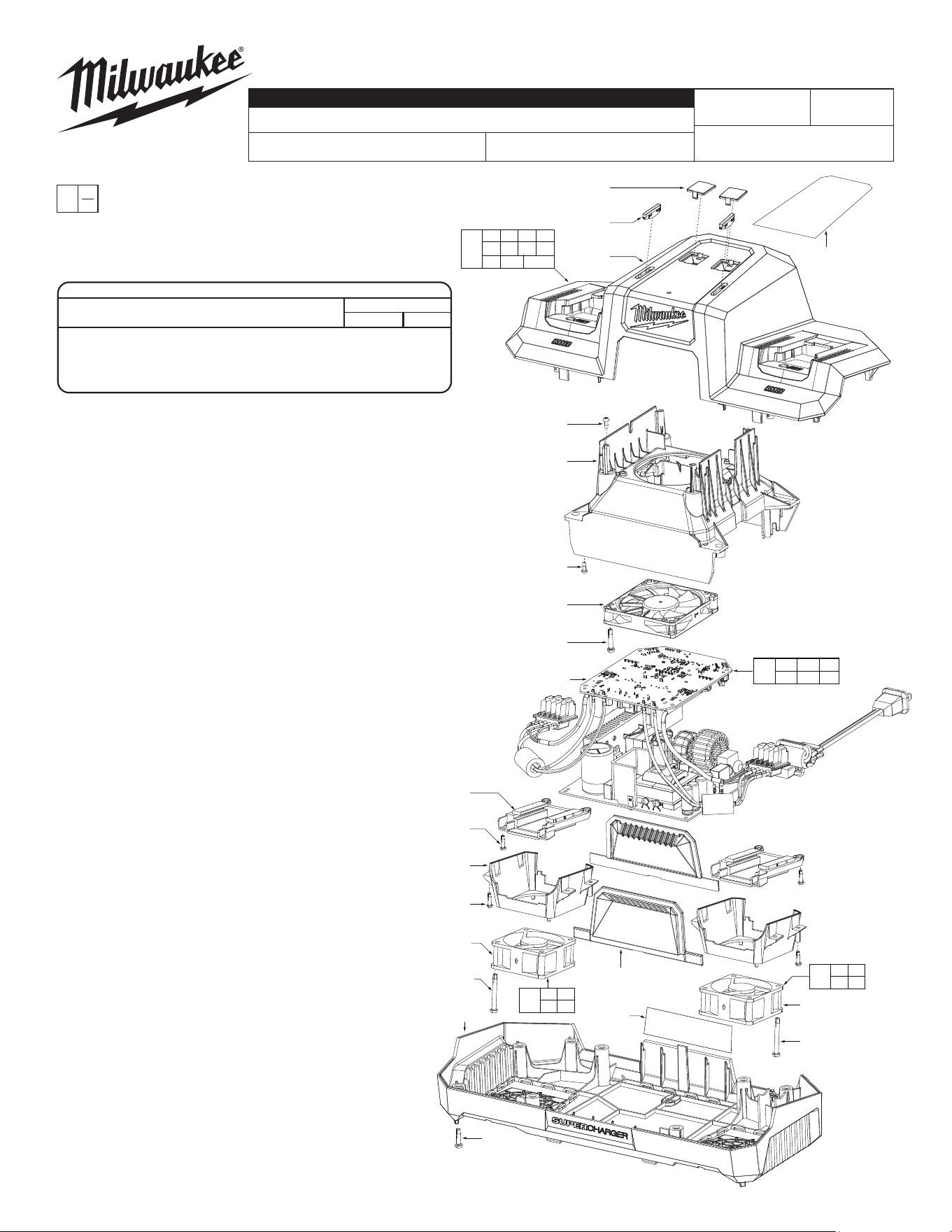
48-59-1815
M18™ Dual Bay Simultaneous Super Charger
Feb. 2024
FIG. PART NO. DESCRIPTION OF PART NO. REQ.
1 --------------- Charger Indicator Lens (2)
2 --------------- Charger Status Lens (2)
3 --------------- Top Housing (1)
4 05-81-1195 M3 x 8mm Screw (24)
5 --------------- PCBA Frame (1)
6 --------------- PCBA Cooling Fan Assy. (1)
7 06-82-0011 M4 x 20mm Screw (2)
8 --------------- Interface Back Plate (2)
9 --------------- Pack Cooling Duct (2)
10 --------------- Side Plate (2)
11 --------------- Left Pack Cooling Fan Assy (1)
12 --------------- Right Pack Cooling Fan Assy (1)
13 06-82-4002 M4 x 35mm Screw (4)
14 --------------- Bottom Housing (1)
15 06-82-4003 M4 x 16mm Screw (12)
18 --------------- PCBA Assy. (1)
20 10-22-0261 UI Label (1)
21 12-20-0318 Service Nameplate (1)
30 31-50-0059 Housing Service Kit (1)
31 14-20-0802 Main PCBA Service Kit (1)
32 14-46-0351 Left Pack Cooling Fan Service Kit (1)
33 14-46-0352 Right Pack Cooling Fan Service Kit (1)
FIG. NOTES
20,21 A clean, dry surface is essential for proper perfor-
mance for any adhesive system. The area intended
for application of any adhesive label or nameplate
must be prepared by cleaning with isopropyl alcohol.
The solvent is to be applied with a clean, lint free
applicator and the surface allowed to dry before ap-
plying the label or nameplate.
54-04-1861
REVISED BULLETIN
SERVICE PARTS LIST
BULLETIN NO.
WIRING INSTRUCTION
DATE
CATALOG NO.
SPECIFY CATALOG NO. AND SERIAL NO. WHEN ORDERING PARTS
EXAMPLE:
Component Parts (Small #)
Are Included When Ordering
The Assembly (Large #).
0
00
N85B
1
(2x)
2
(2x)
3
20
4
(4x)
5
4
(4x)
6
7
(2x)
18
8
(2x)
4
(8x)
9
(2x)
4
(8x)
11
12
13
(2x)
10
(2x)
21
14
13
(2x)
15
(12x)
4 9
11 13
32
4 9
12 13
33
4 5 6
7 18
31
1 2 3 4
8 10 14 15
20 21a
30
MILWAUKEE TOOL
l
www.milwaukeetool.com
13135 W. LISBON RD., BROOKFIELD, WI 53005
Drwg. 1
TORQUE SPECIFICATIONS
SEAT TORQUE
FIG. PART NO. WHERE USED (kgf-cm) (lb-in)
4 06-82-1087
PCBA Frame/Interface/Cooling Duct
6-8 5-7
7 06-82-0011 PCBA Cooling Fan Assy. 5-7 4-6
13 05-78-0307 Pack Cooling Fan Assy. 5-7 4-6
15 06-82-4003 Housing 9-11 8-10
54-04-1860
SERIAL NO.
See Page 2
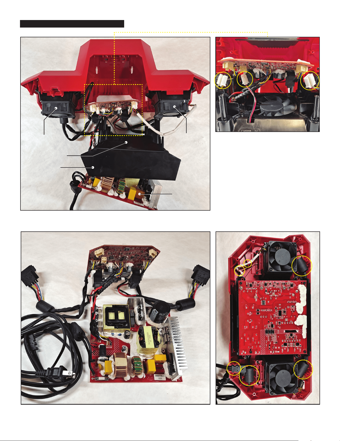
Right Pack
Cooling Fan
PCBA Frame
PCBA Board
Left Pack
Cooling Fan
A
B
C
Detailed view of connectors to PCBA board from
A) Right Pack Cooling Fan, B) PCBA Cooling Fan
and C) Left Pack Cooling Fan.
Before reassembling the bottom housing to the top
housing, be sure there are no interferences with
wires, and wires are placed within channels as
shown above.
Internal components of charger shown, with screws removed that connect PCBA Assembly
to the PCBA Frame.
PCBA Assembly, which includes power cord, terminal blocks, AC board and DC board.
PCBA Cooling Fan
M18 Dual Bay Super Charger Wiring