Operator’s Manual
www.mechmaxx.com
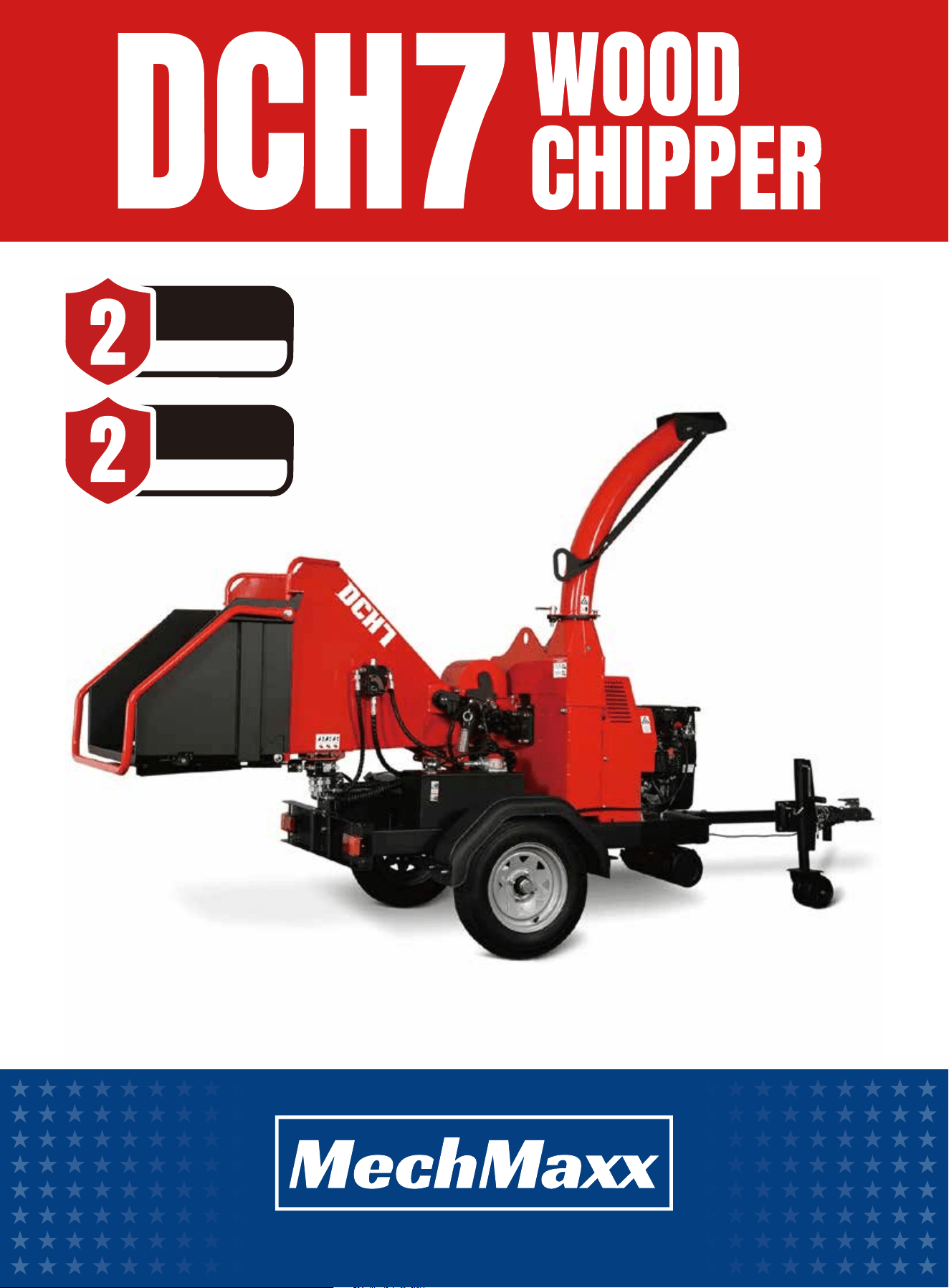
ENGINE WARRANTY
YEARS
YEARS
MACHINE WARRANTY

TABLE OF CONTENTS
TABLE OF CONTENTS
SPECIFICATIONS
SAFETY SIGNS
SAFETY
1
2
9
4
5
14
KNOW YOUR MACHINE
15
OPERATING INSTRUCTIONS
21
22
MAINTENANCEUNPACKING THE CONTAINER
10
CONTENTS SUPPLIED
11
TO-SCALE HARDWARE
12
ASSEMBLY
29
TROUBLESHOOTING
1
www.mechmaxx.com
TABLE OF CONTENTS
TRANSPORTATION
INTRODUCTION
Do not start or operate the machine before
you read this manual. Make sure that you
fully understand all the safety, operation,
and maintenance information before you
operate the machine.
Keep this manual with the machine at all
times and available for frequent reference.
Congratulations on your purchase of the MechMaxx wood
chipper!
This manual provides all the information you need to
operate and maintain your machine safely and effectively.
Read and understand the entire manual before use. If you
have questions that are not addressed here, contact
MechMaxx Customer Support for assistance.
This machine is designed for specific applications only.
We strongly recommend not modifying or using it for any
purpose other than its intended use. If you have questions
about a specific application, DO NOT operate the machine
until you contact us first to confirm it is suitable for that
use.
The engine manufacturer is responsible for all issues
related to engine performance, power rating, specifica-
tions, warranty, and service. Consult the engine manufac-
turer’s owner/operator manual for details.
Record the model and serial number as well as date and
place of purchase for future reference. Have this informa-
tion available when ordering parts or optional accessories
and when making technical or warranty inquiries.
This manual is subject to change without notice. For the
most current information, go to Mechmaxx.com.
For available accessories, go to mechmaxx.com.
ENGINE MANUAL
MODEL AND SERIAL NUMBERS

SPECIFICATIONS
2
www.mechmaxx.com
SPECIFICATIONS
Engine
Engine Type
Displacement
Rated Power
Max. Net Torque
Fuel Capacity
Recommended Oil
Hydraulic Tank
Starting
Battery
Ignition System
Governor System
Belt
Belts Material
Clutch
Cutting Method
Max. Chipping Dia.
Feed Roller
Blade
Blade Material
Blades Type
Flywheel System
Discharge Chute
Emergency Stop
Towing Length
Wheel
Wheelbase
Axle
Max. Speed
HONDA GX690
Air Cooled 4-Stroke OHV Petrol Engine,
90°V-Twin Design, Horizontal Shaft
688 cc; 22 HP
13.0 kW / 3600 RPM
48.3 N·m/2500 RPM
3.17 gal
SAE 10W-30 Classification SE or Higher
6.87 gal
Electric Starting
36Ah 12V Lead-Acid Battery
CDI
Mechanical Centrifugal Type
2 x V-Belts
Kevlar
Centrifugal Clutch
Disc
7 in
7.5 in x 6.5 in
2 x Blades; 1 x Anvil
A8 (5Cr8MoVSi)
Double Edge Blade
Open Top Flywheel 26 in x1 in Twin
360 Degree Rotating
Stop Bar
Tow Bar With 2 in Coupler
5.3-12 Tubeless
52.5 in
Damping Torsion Axle
50 mph
ZONSEN GB750
Dual Cylinder ( 90° V Type ),
4 Stroke, Forced Air Cooling
750 cc;25 HP
15.5 kW / 3600 RPM
45 N·m / 2800 RPM
2 x 8 in Blades; 2 x 6 in Anvil
3
www.mechmaxx.com
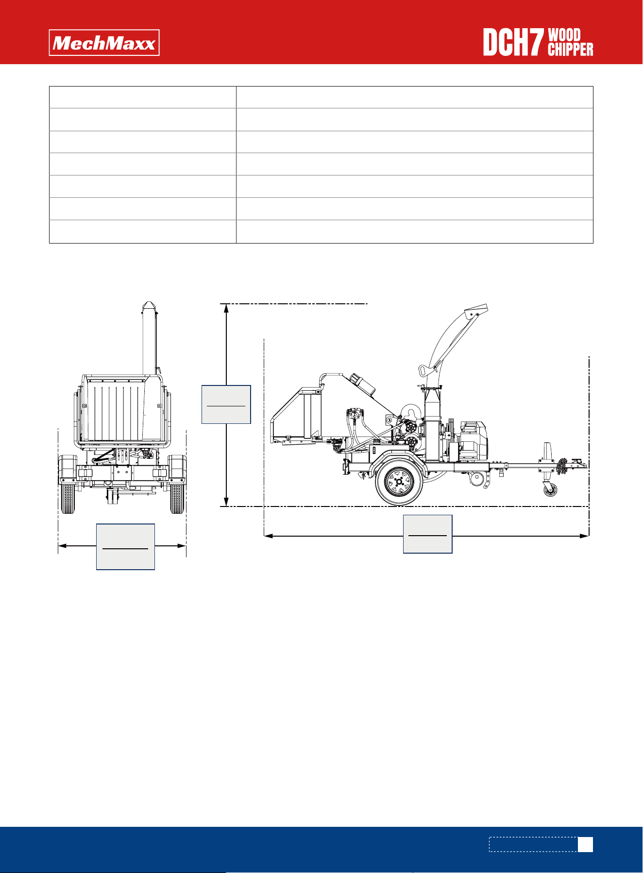
OVERALL DIMENSIONS
OVERALL DIMENSIONS
2300mm
90.5”
1390mm
54.7”
3613mm
142”
Channel Steel Welded Frame
Iron Fram With Black Film
1389/1587 Ibs
137 x 55 x 90 in
87 x 46 x 51 in
2 Years
2 Years
Chassis
Package Method
Weight (N.W./G.W.)
Product Size (L*W*H)
Packing Size (L*W*H)
Machine Warranty
Engine Warranty
4
www.mechmaxx.com
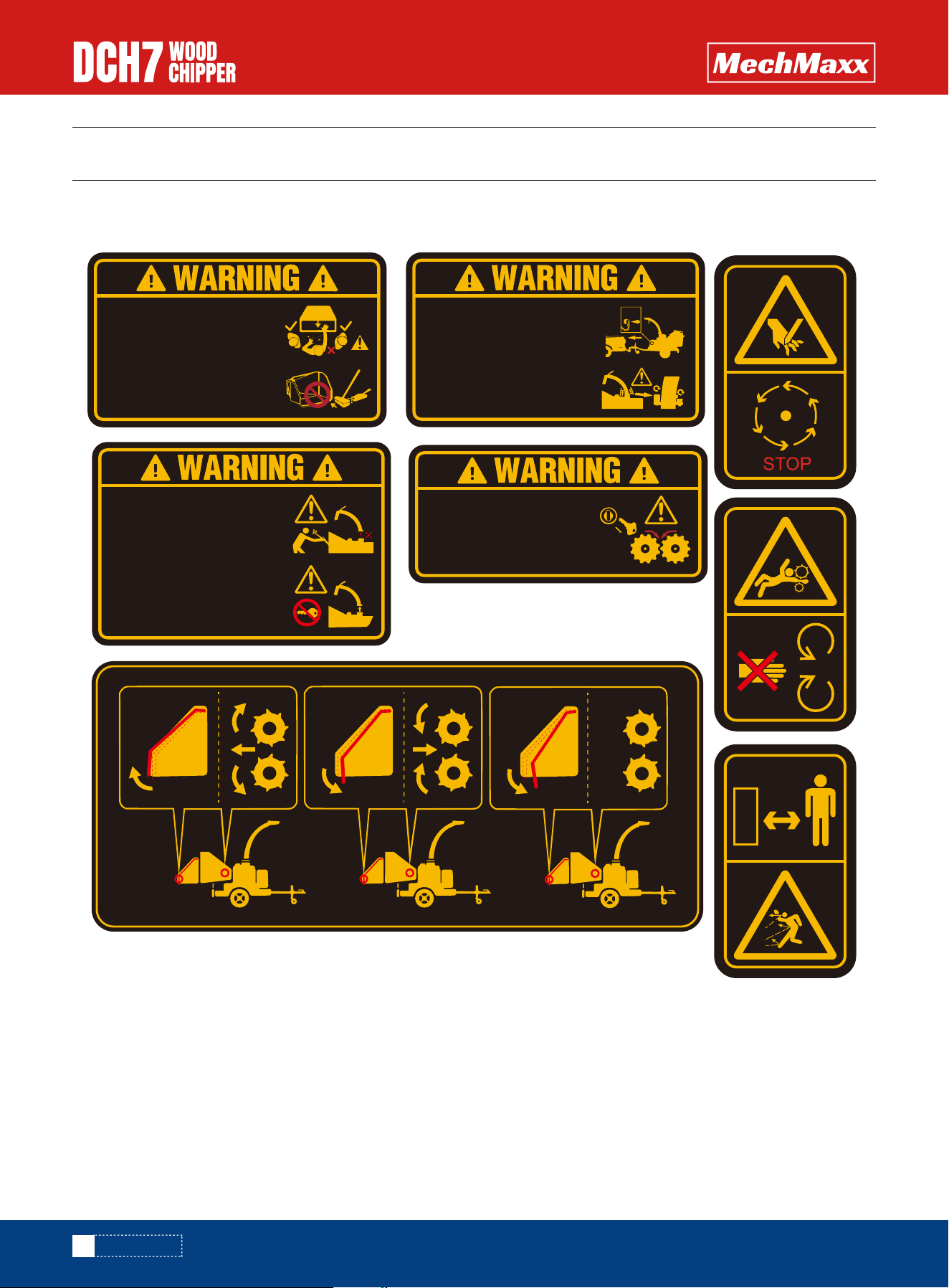
SAFETY SIGNS
SAFETY SIGNS
The rating plate on your machine may show symbols. These represent important information about the product or instruc-
tions on its use.
WHEN TRANSPORTING,
DISCHARGE CLAMPS MAY WORK
LOOSE.CHECK FREQUENTLY.
ALWAYS COVER IGNITION SWITCH
WITH PLUG PROVIDED WHEN
TOWING OR JET WASH CLEANING.
STOP
DO NOT USE THIS MACHINE
WITHOUT THE DISCHARGE UNIT
FITTED. FAILURE TO COMPLY MAY
RESULT IN SERIOUS INJURY OR
DAMAGE.
ROTATING BLADES INSIDE.STOP
ENGINE AND REMOVE KEY
BEFORE REMOVING DISCHARGE
UNIT.
AVOID STANDING DIRECTLY IN
FRONT OF FEED FUNNEL TO
REDUCE EXPOSURE TO NOISE,
DUST AND RISK FROM EJECTED
PARTICLES.
DO NOT PUT ROAD SWEEPINGS
IN MACHINE AS GRIT WILL
DAMAGE BLADES.
AUTO FEED SYSTEM FITTED.
ROLLERS MAY TURN WITHOUT
WARNING!WHEN THE ENGINE IS
SWITCHED OFF THE ROLLERS
WILL TURN DURING THE RUN
DOWN PERIOD.

5
www.mechmaxx.com
GENERAL SAFETY RULES
SAFETY
SAFETY
Read this manual and labels affixed to the machine to
understand its limitations and potential hazards.
Always keep hands and feet away from all moving parts
during operation. Moving parts can cut or crush body
parts.
Do not touch parts that might be hot from operation.
Allow parts to cool before attempting to maintain, adjust,
or service.
Do not overreach. Do not operate the machine while
barefoot or when wearing sandals or similar lightweight
footwear. Wear protective footwear that will protect your
feet and improve your footing on slippery surfaces. Keep
proper footing and balance at all times. This enables
better control of the machine in unexpected situations.
Check your machine before starting it. Keep guards in
place and in working order. Make sure all nuts, bolts, etc.,
are securely tightened.
Never operate the machine when it is in need of repair or
is in poor mechanical condition. Replace damaged, miss-
ing, or failed parts before using it. Check for fuel leaks.
Keep the machine in safe working condition.
Do not use the machine if the engine's switch does not
turn it on or off. Any gasoline powered machine that can't
be controlled with the engine switch is dangerous and
must be replaced.
Regularly check to see that keys and adjusting wrenches
are removed from the machine area before starting it. A
wrench or a key that is left attached to a rotating part of
the machine may result in personal injury.
Avoid accidental starting. Be sure the engine's switch is
off before transporting the machine or performing any
maintenance or service on the unit. Transporting or
performing maintenance or service on a machine with its
switch on invites accidents.
If the machine should start to vibrate abnormally, stop
the engine and check immediately for the cause. Vibra-
tion is generally a warning sign of trouble.
Stay alert, watch what you are doing, and use common
sense when operating the machine.
Always keep hands and feet away from all pinch points.
Be thoroughly familiar with the controls and their proper
operation. Know how to stop the machine and disengage
the controls quickly.
Make sure to read and understand all the instructions and
safety precautions as outlined in the Engine Manufactur-
er's manual packed separately with your unit. Do not
attempt to operate the machine until you fully understand
how to properly operate and maintain the engine and how
to avoid accidental injuries and/or property damage.
If the unit is to be used by someone other than original
purchaser or loaned, rented, or sold, always provide this
manual and any needed safety training before operation.
The user can prevent and is responsible for accidents or
injuries that may occur to themselves, other people, and
property.
Do not permit children to operate this machine at any
time.
Keep children, pets, and other people not using the unit
away from the work area. Be alert and shut off unit if
anyone enters work area. Keep children under the watch-
ful care of a responsible adult.
Do not operate the machine while under the influence of
drugs, alcohol, or any medication that could affect your
ability to use it properly.
Dress properly. Wear heavy long pants, boots, and gloves.
Do not wear loose clothing, short pants, or jewelry of any
kind. Secure long hair so it is above shoulder level. Keep
your hair, clothing, and gloves away from moving parts.
Loose clothes, jewelry, or long hair can be caught in
moving parts.
Protect eyes, face, and head from objects that may be
thrown from the unit. Always wear safety goggles or
safety glasses with side shields when operating.
Do not force the machine. Use the correct machine for
your application. The correct machine will do the job more
efficiently and safer at the rate it was designed.
Wear appropriate hearing protection.
PERSONAL SAFETY
INSPECT YOUR MACHINE

6
www.mechmaxx.com
SAFETY
This machine is equipped with an internal combustion
engine. Do not use on or near any unimproved, forest
covered, or brush covered land unless the exhaust system
is equipped with a spark arrester meeting applicable
local, state, or federal laws.
Never start or run the engine inside a closed area. The
exhaust fumes are dangerous, containing carbon monox-
ide, an odorless and deadly gas. Operate this unit only in a
well-ventilated outdoor area.
Do not tamper with the engine to run it at excessive
speeds. The maximum engine speed is preset by the
manufacturer and is within safety limits. See engine
manual.
Keep a Class B fire extinguisher on hand when operating
this Wood chipper in dry areas as a precautionary
measure.
Fuel is highly flammable, and its vapors can explode if
ignited. Take precautions when using to reduce the
chance of serious personal injury.
When refilling or draining the fuel tank, use an approved
fuel storage container while in a clean, well-ventilated
outdoor area. Do not smoke, or allow sparks, open flames,
or other sources of ignition near the area while adding fuel
or operating the unit. Never fill the fuel tank indoors.
Keep grounded conductive objects, such as tools, away
from exposed, live electrical parts and connections to
avoid sparking or arcing. These events could ignite fumes
or vapors.
Always stop the engine and allow it to cool before filling
the fuel tank. Never remove the cap of the fuel tank or
add fuel while the engine is running or when the engine is
hot. Do not operate the machine with known leaks in the
fuel system.
Never overfill the fuel tank. Fill the tank to no more than
1/2" below the bottom of the filler neck to provide space
for expansion as the heat of the engine can cause fuel to
expand.
Replace all fuel tank and container caps securely and
wipe up spilled fuel. Never operate the unit without the
fuel cap securely in place.
Loosen the fuel tank cap slowly to relieve any pressure in
the tank.
Avoid creating a source of ignition for spilled fuel. If fuel
is spilled, do not attempt to start the engine but move the
machine away from the area of spillage and avoid creating
any source of ignition until fuel vapors have dissipated.
When fuel is spilled on yourself or your clothes, wash your
skin and change clothes immediately.
Store fuel in containers specifically designed and
approved for this purpose.
Store fuel in a cool, well-ventilated area, safely away from
sparks, open flames, or other sources of ignition.
Never store fuel or a machine with fuel in the tank inside
a building where fumes may reach a spark, open flame, or
any other source of ignition, such as a water heater,
furnace, or clothes dryer. Allow the engine to cool before
storing in any enclosure.
Identify hazards and take preventive steps to avoid
accidents and minimize risk. Possible hazards include,
but are not limited to, moving parts, thrown objects,
weight of the machine and components, and the operat-
ing environment.
Thoroughly inspect the area in which you are working,
keeping it clean and free of debris to prevent tripping.
Operate on a flat level ground.
Before starting your chipper shredder: make sure the feed
hopper and cutting housing are empty and free of all
debris, check the oil level, make sure all nuts and bolts
are tight, and check the air pressure in the tires.
Never place any part of your body where it would be in
danger if movement should occur during assembly, instal-
lation, operation, maintenance, repair, or moving.
Never place your hands, feet, or any part of your body in
the chipper hopper, discharge opening, or near or under
any moving part while the machine is running. Keep the
area of discharge clear of people, animals, buildings,
glass, or anything else that will obstruct clear discharge,
causing injury or damage. Wind can also change
discharge direction, so be aware. If it becomes necessary
to push materials to the chipper hopper, use a small-di-
ameter stick, not your hands.
Keep all bystanders and pets at least 75 feet away. If you
are approached, stop the unit immediately.
ENGINE SAFETY
FUEL SAFETY
SPECIFIC SAFETY RULES
PRIOR TO STARTING
OPERATION SAFETY

7
www.mechmaxx.com
SAFETY
Keep your face and body back from the chipper hopper and
discharge chute to avoid injury from accidental bounce
back of material.
Feed only clean materials into the machine. Foreign
matter such as soil, sand, grit, stones, pieces of
metal,etc. will damage the sharp edge of the cutting
knives. Root balls and dead wood will also dull the blades
quickly
Avoid feeding pine needles, flax and cabbage tree leaves
into the machine; these stringy materials can wrap
around the rotor shaft and work their way into the bearing.
Avoid feeding short, stubby pieces of wood into the
machine; they tend to bounce and spin in the feed hopper.
Feed these short pieces together with longer pieces.
After becoming familiar with the machine, prune to suit
its capabilities.
This machine is self-feeding, do not force branches into
the blades. Allow the machine to automatically feed
through. Allow time for the machine to reach the highest
spinning revolutions before feeding the next load of
branches.
• Always stop the chipper engine before making any
adjustments, refuelling or cleaning.
• Always check the rotor has stopped rotating and
remove the chipper ignition key before maintenance of
any kind, orwhenever the machine is to be left
unattended. If in doubt, look through the in-feed funnel
to see if rotor is stillmoving.
• Always check the machine is well supported and cannot
move. If working on an incline, position on solid
ground,across the slope.
• Always operate the chipper with the engine set to maxi-
mum speed when chipping.
• Always check (visually) for fluid leaks. If found, resolve
the leak before operating the chipper.
• Always take regular breaks. Wearing personal protec-
tive equipment for long periods can be tiringand hot.
• Always keep hands, feet and clothing out of feed open-
ing, discharge and moving parts.
• Always use a push stick to push in short pieces. Under
no circumstances should you reach intothe funnel.
• Always keep the operating area clear of people, animals
and children.
• Always keep the operating area clear from debris build
up.
• Always keep clear of the chip discharge tube. Foreign
objects may be ejected with great force.
• Always ensure protective guarding is in place before
commencing work. Failure to do so mayresult in person-
al injury or loss of life.
• Always operate the chipper in a well ventilated area -
exhaust fumes are dangerous.
• Ensure a fire extinguisher is available on site.
• Ensure a personal first aid kit and hand cleaning materi-
als are available (e.g. waterless skin cleanser).
• Always cover ignition switch with plug provided when
towing or jet wash cleaning.
Never allow processed material to build up in the
discharge area. This can prevent proper discharge and
result in kickback from the chipper hopper.
Never attempt to unclog either the feed hopper or
discharge chute while the engine is running. Immediately
shut off the engine, allow the cutting disk to come to a
complete stop, and then remove the clogged material.
Inspect for damage and check for any loose parts for
repair or replacement.
Whenever you leave the operating position or if you have
to remove processed material, leaves, or debris from the
machine, always shut down the engine, and ensure the
engine is switched to"off" to prevent accidental starting,
and wait for all moving parts to come to a complete stop.
Before opening the cutting disk housing, always make
sure the engine is switched off, the cutting disk is at a
complete standstill, and the belt drive is disengaged.
Move the machine at least 10 feet away from the refuel-
ing point before starting engine.
This chipper shredder is for movement by hand only. Never
attempt to tow the machine on public highways, roads,or
thoroughfares.
Never reach with your hands inside the feed hopper past
the rubber flap while operating the machine.
Keep combustible substances away from the engine
when it is hot.
Do not tilt the machine while the engine is running
Never operate this machine without the feed hopper or
discharge chute properly attached.
FEEDING MATERIALS
GENERAL SAFETY MATTERS
UNCLOGGING
MOVING

8
www.mechmaxx.com
SAFETY
This machine has two rotating cutting knives capable of
amputating hands and feet and throwing objects. Keep
hands and feet out of openings while machine is running.
Failure to observe these safety instructions could result
in serious injury or death.
Avoid contact with hot fuel, oil, exhaust fumes and hot
surfaces. Do not touch the engine or muffler. These parts
get extremely hot from operation. They remain hot for a
short time after you turn off the unit. Allow the engine to
cool before doing maintenance or making adjustments.
• Maintain a safety exclusion zone around the chipper of
at least 10 metres for the general public or employees
without adequate protection. Use hazard tape to identi-
fy this working area and keep it clear from debris build
up. Chips should be ejected away from any area the
general public have access to.
• Hazardous material - Some species of trees and bushes
are poisonous. The chipping action can produce vapour,
spray and dust that can irritate the skin. This may lead
to respiratory problems or even cause serious poison-
ing. Check the material to be chipped before you start.
Avoid confined spaces and use a face mask if neces-
sary.
• Be aware when the chipper is processing material that
is an awkward shape. The material can move from side
to side in the funnel with great force. If the material
extends beyond the funnel, the brash may push you to
one side causing danger. Badly twisted brash should be
trimmed before being chipped to avoid thrashing in the
feed funnel.
• Be aware that the chipper can eject chips out of the
feed funnel with considerable force. Always wear full
head and face protection.
• Always work on the side of the machine furthest from
any local danger, e.g. not road side.
• Never leave the chipper unattended when running.
Machines must be supervised at all times when in use.
• In the event of an accident, stop the machine, remove
the key and call the emergency services immediately.
If the machine should start to make an unusual noise or
vibration, immediately shut off the engine, disconnect the
spark plug wire, and check for the cause. Unusual noise or
vibration is generally a warning of trouble.
Keep the engine and muffler free of grass, leaves, exces-
sive grease or carbon build up to reduce the chance of a
fire hazard.
Never douse or squirt the unit with water or any other
liquid. Keep handles dry, clean and free from debris. Clean
after each use.
When storing machine out of the reach of children and do
not allow persons unfamiliar with the machine or these
instructions to operate it. This machine can be dangerous
when used by an untrained user.
Some parts of this machine are made of plastic or rubber
and should be kept away from chemicals.
Do not alter or adjust any part of the chipper shredder or
its engine that is sealed by the manufacturer or distribu-
tor. Only a qualified service technician may adjust parts
that increase or decrease governed engine speed.
To maintain your machine, check for any misalignment or
binding of any moving parts. Parts that are broken or worn
down that may affect the machine's operation. If damage
or worn parts are identify, they should be repaired before
use. Many accidents are caused by poorly maintained
equipment.
Never cover the machine while the muffler is still hot.
Observe proper disposal laws and regulations for gas, oil,
etc. to protect the environment.
Use only attachments and accessories approved by the
manufacturer. Failure to do so can result in personal
injury.
Do not put hands or feet near rotating parts.
The operator should be aware of the following points:
Position the machine in such a way that it can not move
during maintenance, cleaning, adjustment, assembly of
accessories or spare parts, as well as under storage
Do not force the machine. Use the correct machine for
your application. The correct machine will do the job
better and safer at the rate for which it is designed.
Do not change the engine governor settings or over-speed
the engine. The governor controls the maximum safe
operating speed of the engine.
Do not run the engine at a high speed when youare not
working.
Always stop the engine before moving the machine, and
watch out for sharp objects that could pierce the tires.
MACHINE USE AND CARE
MAINTAINING YOUR MACHINE
BASIC WOODCHIPPING SAFETY
9
www.mechmaxx.com
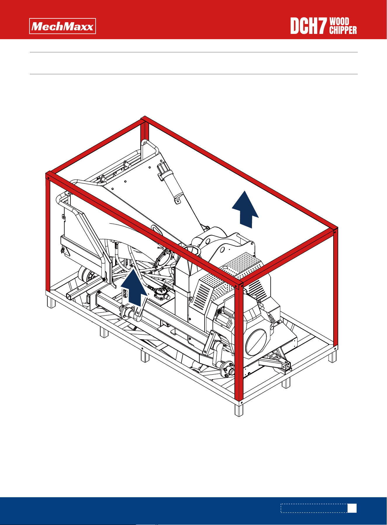
UNPACKING THE CONTAINER
UNPACKING THE CONTAINER
Remove the packaging frame of the machine using a tool.
CONTENTS SUPPLIED
CONTENTS SUPPLIED
10
www.mechmaxx.com
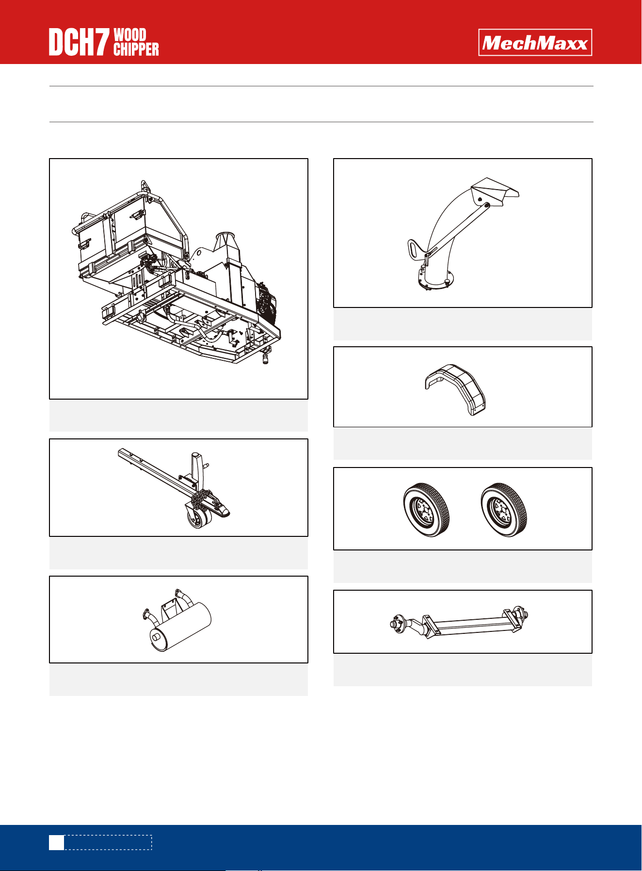
Your Wood chipper comes partially assembled and contains the following:
Verify all component and hardware quantities are correct prior to assembling the Wood chipper.
Engine and base frame1x
1x
1x
Mudguard
1x
Expulsion Chute
Tow bar
1x
1x
Muffler
1x
Wheels
Axle
TO-SCALE HARDWARE
TO-SCALE HARDWARE
11
www.mechmaxx.com
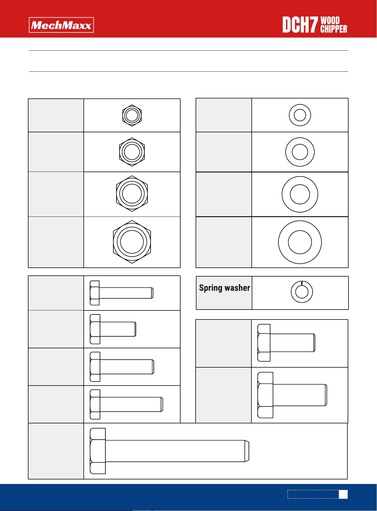
Hardware graphics are printed at 1:1 scale for ease of identification. Simply place the hardware over the image in the
tables to verify it is the correct size.
M6 X 30mm
Hex bolt
8X
M8 X 30mm
Hex bolt
4X
M8 X 35mm
Hex bolt
2X
M10 X 25mm
Hex bolt
6X
M12 X 30mm
Hex bolt
4X
M12 X 30mm
Hex bolt
2X
M8 X 20mm
Hex bolt
2X
6
Flat washer
8X
8
Flat washer
14X
8X
10
6
Flat washer
6X
12
Flat washer
4X
8X
nut M6
Hex lock
12X
nut M8
Hex lock
4X
nut M10
Hex lock
2X
nut M12
Hex lock
12
www.mechmaxx.com
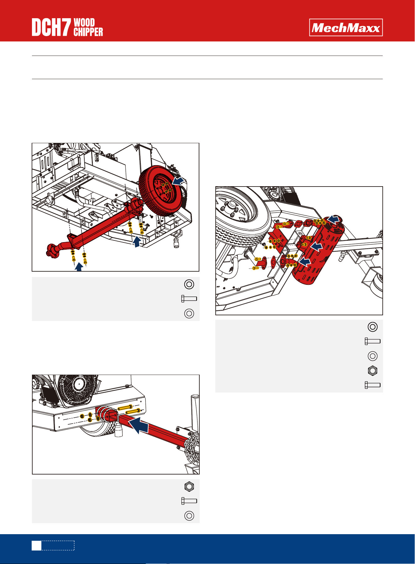
ASSEMBLY
Attach the torsion axle to the chassis using a flat washer
(12), hex bolt (M12x30), and spring washer (12).
Attach the wheel to the torsion axle using a flange spheri-
cal nut. (See Figure 1)
Attach the tow bar to the chassis using a hex bolt
(M12x80), flat washer (12), and lock nut (M12). (See
Figure 2)
Attach the muffler gasket to the middle of exhaust pipe 2,
exhaust pipe 1, and the muffler.
Attach the muffler to exhaust pipe 2 and exhaust pipe 1
using a hex bolt (M8x30), flat washer (8), spring washer,
and hex nut (M8).
Attach the muffler to the chassis using a hex bolt
(M8x20), flat washer (8), spring washer (8), and hex nut
(M8). (See Figure 3)
ASSEMBLY
Hex lock nut M86X
Hex bolt M12 X 30mm
Flat washer 12
4X
4X
Hex bolt M8 X 20mm
Flat washer 8
2X
Hex bolt M8 X 30mm4X
6X
Hex lock nut M122X
Hex bolt M12 X 80mm
Flat washer 12
2X
2X
Figure 2
Figure 3
Figure 1
Spring washer 86X
Spring washer 124X
AXLE
TOW BAR
MUFFLER
13
www.mechmaxx.com
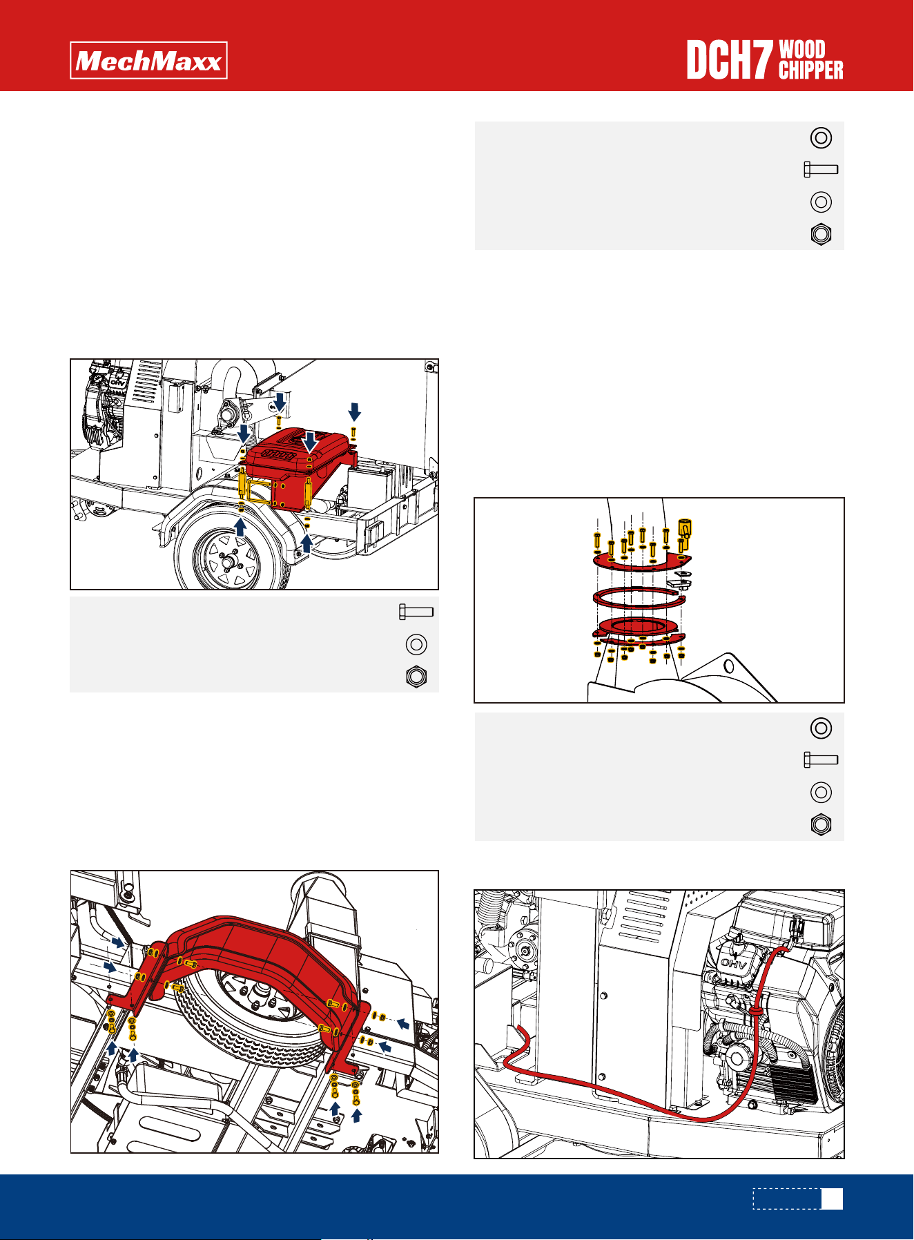
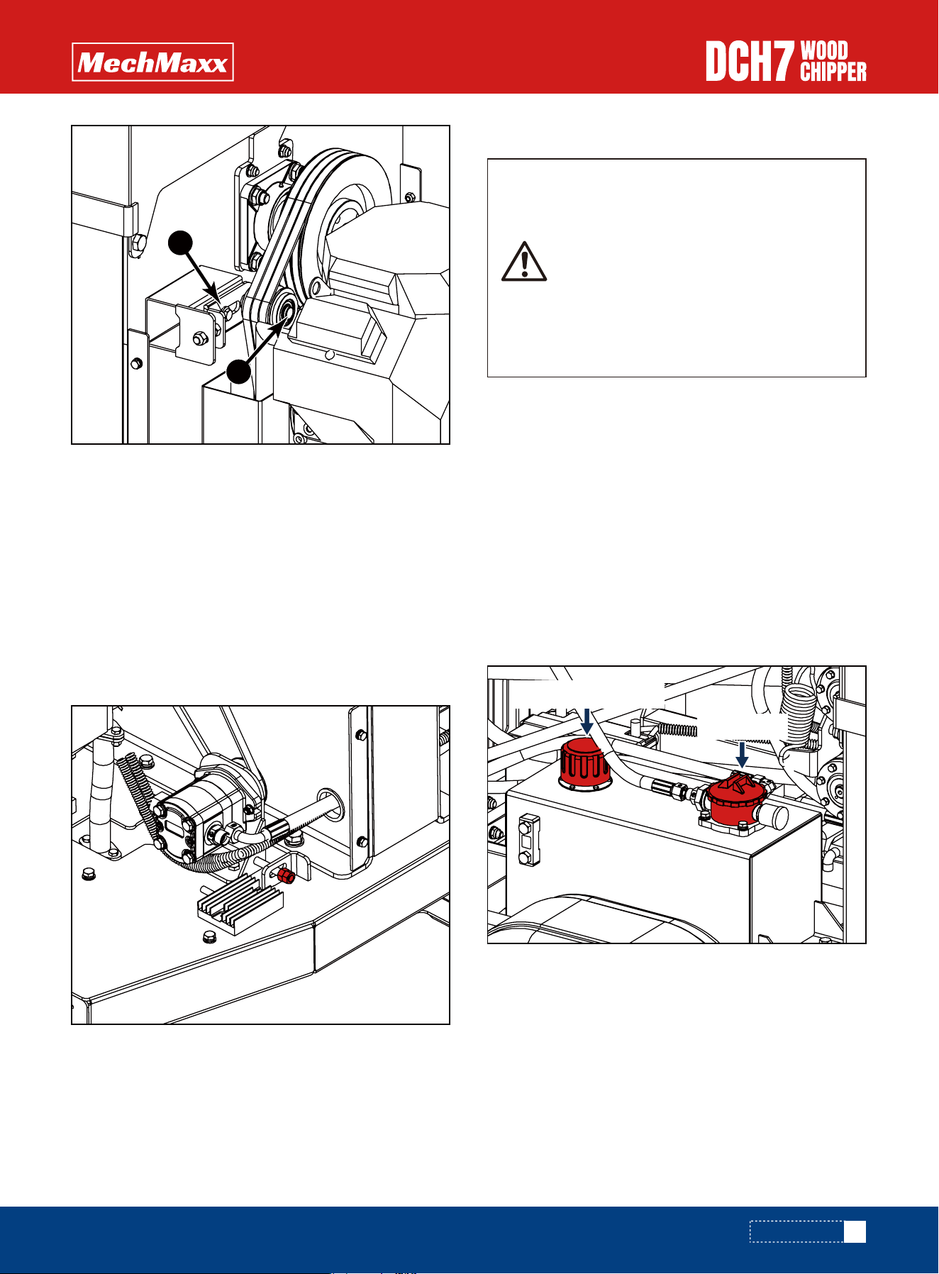
ASSEMBLE
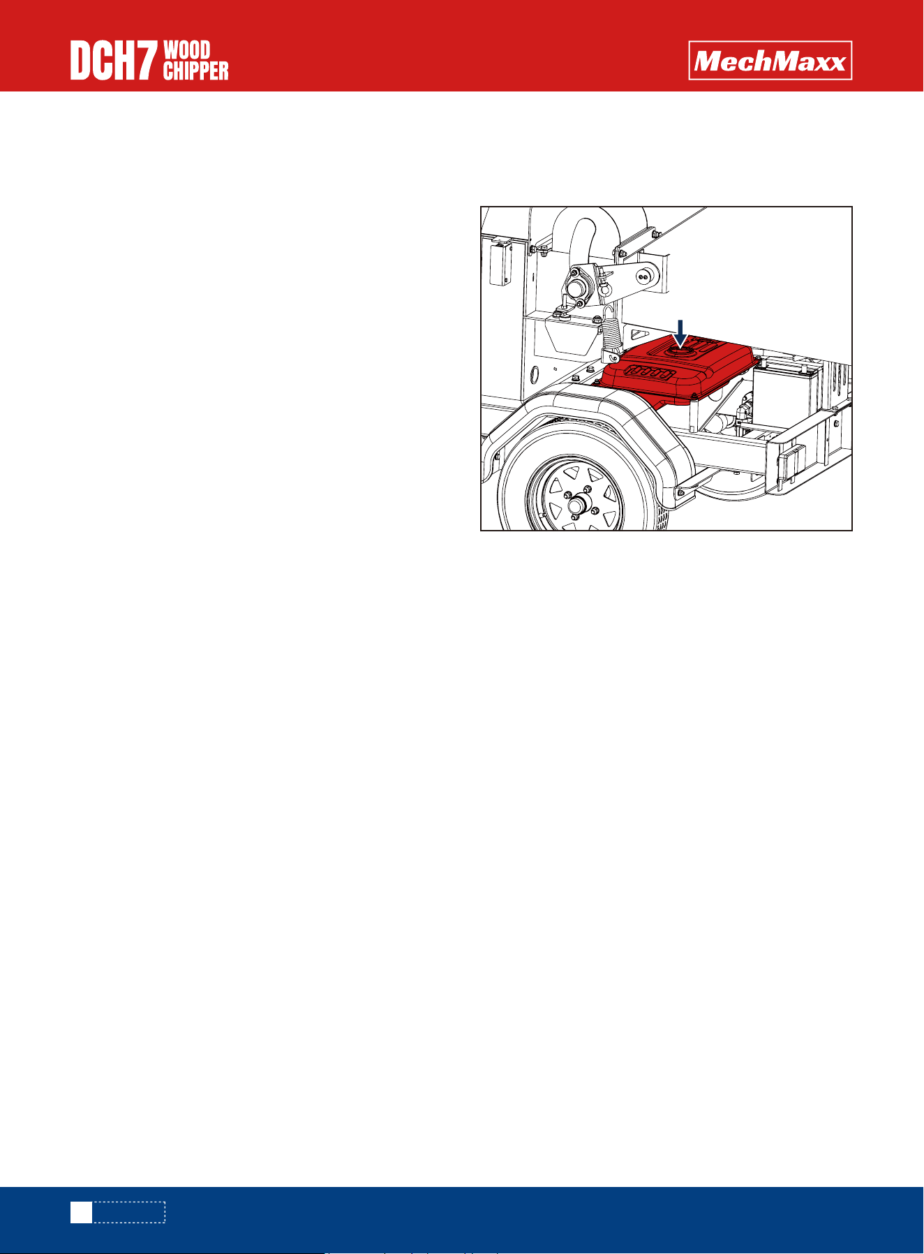
Attach the fuel tank rack to the torsion axle using a
U-bolt, flat washer (8), and lock nut (M8).
Attach the fuel tank to the fuel tank rack.
Attach the fuel tank fixing plate to the fuel tank.
Attach the lower end of the fuel tank fixing plate to the
fuel tank rack using a hex bolt (M8x35), flat washer, and
lock nut (M8).
Attach the upper end of the fuel tank fixing plate to the
chassis using a hex bolt (M8x35), flat washer (8), and
lock nut (M8). (See Figure 4)
Attach mudguard bracket 1 and mudguard bracket 2 to
the chassis using M10x25 bolts, spring washer (10), and
flat washer (10).
Attach the mudguard to mudguard bracket 1 and
mudguard bracket 2 using M10x25 bolts, flat washer
(10), and lock nut (M10). (See Figure 5)
Place the compression plate, rotating gasket, and
discharge chute on the rotor cover in order, and attach
them using M6x30 bolts, flat washer (6), and lock nut
(M6).
Place the clamp and flange plate at the notch of the rotat-
ing gasket, then attach them to the discharge chute
using the handle shaft.
Attach the lever to the handle shaft and mount the hex
nut (M6) on both ends of the lever. (See Figure 6)
Hex lock nut M104X
Hex bolt M10 X 25mm
Flat washer 10
6X
6X
Spring washer 106X
Hex lock nut M68X
Hex bolt M6 X 30mm
Flat washer 6
8X
8X
Spring washer 68X
Hex lock nut M88X
Hex bolt M8 X 35mm
Flat washer 8
2X
8X
FUEL TANK
MUDGUARD
CONNECT THE OIL PIPE TO THE ENGINE.
LOWER EXPULSION CHUTE
Figure 6
Figure 4
Figure 5
KNOW YOUR MACHINE
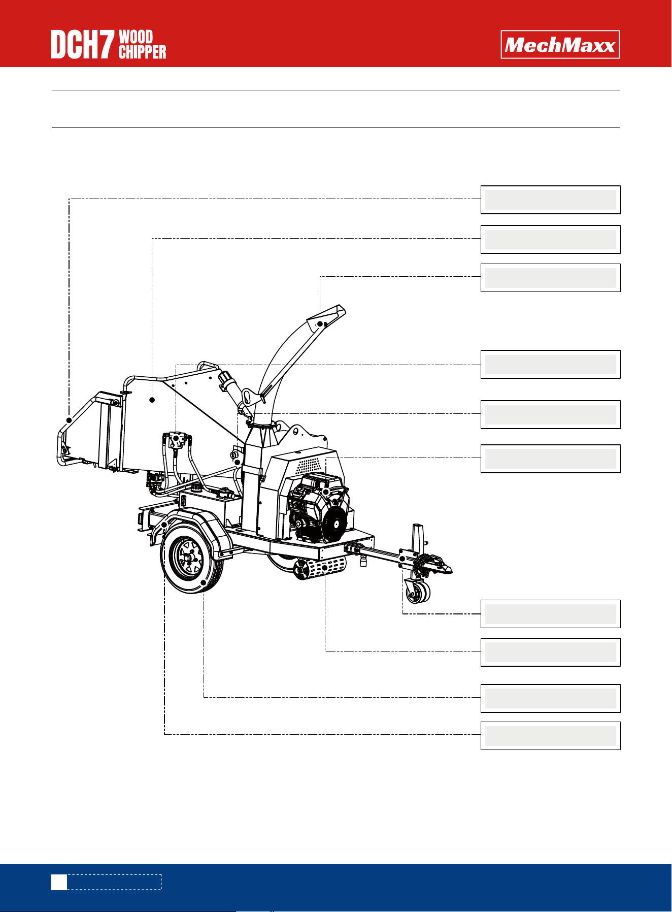
KNOW YOUR MACHINE
14
www.mechmaxx.com
Feed control lever
Deflector
Feed chute
Engine
Hydraulic Motor
Emergency Stop
Coupler
Wheels
Mudguard
Muffler
15
www.mechmaxx.com
OPERATING INSTRUCTIONS
OPERATION
The engine is shipped without oil. Do not
start the engine before adding oil.
ADD OIL TO ENGINE
1. Make sure the chipper shredder is on a flat, level surface.
3. Using a funnel, add oil up to the FULL mark on the
dipstick.
2. Remove the oil fill cap / dipstick to add oil.
DO NOT OVERFILL. Check engine oil level
daily and add as needed.
Gasoline is highly flammable and explo-
sive. You can be burned or seriously
injured when handling fuel. Use extreme
care when handling gasoline.
Fill the fuel tank outdoors, never indoors.
Gasoline vapors can ignite if they collect
inside an enclosure. Explosion can result.
4. Reinstall the fuel cap and tighten. Always clean up
spilled fuel.
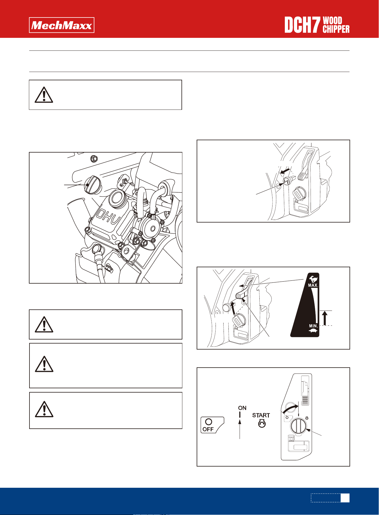
STARTING ENGINE
1. If the fuel tank is equipped with a valve, be sure the
fuel valve is in the OPEN or ON position before attempting
to start the engine.
2. To start a cold engine, pull the choke knob out to the
CLOSED position.
To restart a warm engine, leave the choke knob in the
OPEN position.
3. Move the throttle lever away from the MIN. position,
about 1/3 of the way toward the MAX. position.
4. Turn the engine switch to the ON position.
CHOKE KNOB
OPEN
CLOSED
THROTTLE LEVER
MIN.
MIN.
ENGINE
SWITCH
ON
ON
ON
Oil plug
16
www.mechmaxx.com
OPERATION
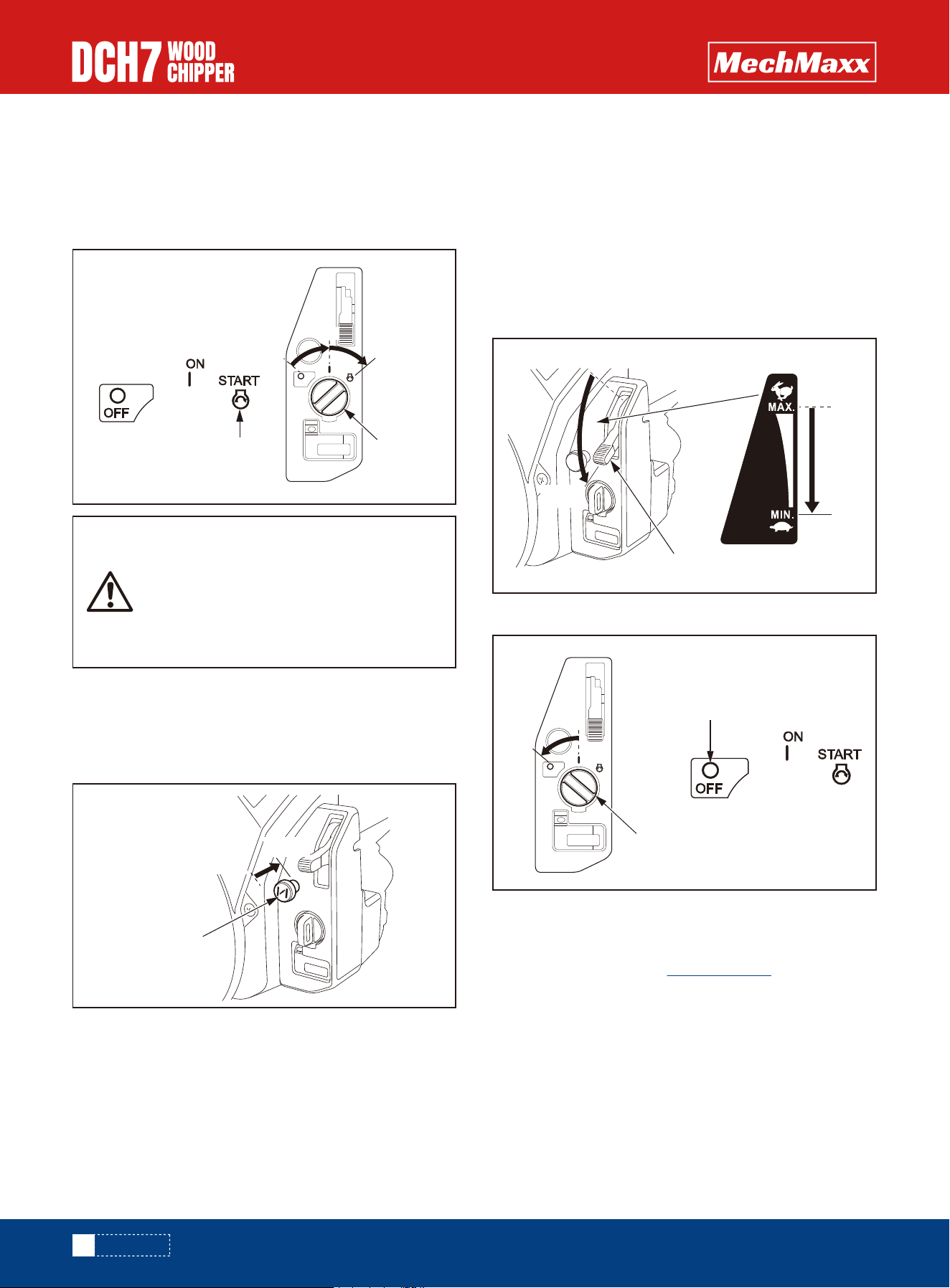
STOPPING THE ENGINE
Using the electric starter for more than 5
seconds at a time will overheat the starter
motor and can damage it.
When the engine starts, release the
engine switch, allowing it to return to the
ON position.
5. Press and hold the starter button.
Turn the engine switch to the START position, and hold it
there until the engine starts. If the engine fails to start
within 5 seconds release the engine switch, and wait at
least 10 seconds before operating the starter again.
To stop the engine in an emergency, simply turn the
engine switch to the OFF position. Under normal condi-
tions, use the following procedure. Refer to the instruc-
tions provided by the equipment manufacturer.
1. Move the throttle lever to the MIN. position. Some
engine applications use a remote-mounted throttle
control rather than the engine-mounted throttle lever
shown here.
2. Turn the engine switch to the OFF position.
3. If the fuel tank is equipped with a valve, turn the fuel
valve to the CLOSED or OFF position.
If different, please go to mechmaxx.com and search for
the machine you purchased and refer to the engine
manual.
6. Warm up the engine for 2 or 3 minutes.
7. If the choke knob was pulled to the CLOSED position to
start the engine, gradually push it to the OPEN position as
the engine warms up.
START
ENGINE
SWITCH
START
NONO
CHOKE KNOB
OPEN
CLOSED
After the engine warms up, pull the throttle lever to accel-
erate engine speed.
OPERATING
THROTTLE LEVER
MIN.
MIN.
ENGINE SWITCH
OFF
OFF
17
www.mechmaxx.com
OPERATION
• Chainsaw safety helmet fitted with visor and recom-
mended ear defenders to an appropriate specification.
• Heavy-duty gloves with elasticated wrist area.
• Keep in mind that the operator or user is responsible for
accidents or hazards occurring to other people, their
property, and themselves.
• Avoid wearing loose clothing or jewelry, which can
catch on moving parts.
• Keep bystanders at least 50 feet (15m) away from your
work area at all times. Stop the engine when another
person or pet approaches.
• Close - fitting heavy-duty non-snag clothing.
• Safety footwear.
• Facemask (if appropriate).
Roller control boxes- a control box is located on either
side of the feed funnel. Their function is to control the
feed roller whilst processing material. They do not control
the main rotor.
RED SAFETY BAR = This is the large red bar that
surrounds the feed tray and side of the feed funnel. The
bar is spring loaded and connected to a switch that will
interrupt the power to the rollers. The switch is designed
so that it only activates if the bar is pushed to the limit of
its travel.
Flow control valve controls the motor rotation speed.
When breaking branches with large diameter, the flow
rate can be appropriately lowered, and the speed can be
adjusted up when the branches are small.
Two hydraulic motors are fixed on the feeding roller and
rotate inopposite directions to roll the wood into the
chipping house.
OPERATOR'S PERSONAL PROTECTIVE
EQUIPMENT REQUIRED
MANUAL CONTROLS
HYDRAULIC MOTOR RATATION AND STOP
FEEDING SPEED ADJUSTMENT
SLOW
FAST
STOP
The chipper shredder can process a wide variety of dry or
green organic materials such as branches, stalks, vines,
leaves, roots, and vegetable matter. The maximum
capacity is 7-inch diameter branches, this can vary
depending on the type and hardness of wood. Rotating
the branch as you feed it into the machine will improve
performance.
The wood chipper can clog up with soft, wet, or fibrous
materials. However, if you feed soft materials intermit-
tently with branches, there should be no problem, as the
wood chipper tends to clean out any residue left in the
machine.
If any stringy material wraps around the rotor shaft,
remove it before it works its way into the bearing.
18
www.mechmaxx.com
OPERATION
Pushing the red Emergency stop button positioned on top
of the funnel kills all power to both the engine and the
rollers, bringing the machine to a complete stop. It
overrides all buttons and bars and will not allow the
chipper to function until it has been reset. To reset, pull
out button until it returns to its original position, turn the
ignition key back to the off position, before restarting the
machine.
The most important part of using a wood chipper is keep-
ing the cutter blades sharp. chipper blades are hollow
ground to an angle of 40 degrees. When performing daily
blade checks ensure blade edge is sharp and free from
chips, if there is any evidence of damage, or the edge is
"dull" change the blade(s). The wood chipper is fitted with
2 blades 8 in long. They are 8 in wide when new. A new
blade should chip for up to 25 hours before it requires
sharpening. This figure will be drastically reduced by
feeding the machine with stony, sandy or muddy material.
It is essential to carry out the following tests to check
safety equipment - this sequence of tests will only take a
few seconds to carry out. We recommend that these
tests are carried out daily. Observing the function as
described will confirm that the safety circuits are working
correctly. This is also a good opportunity to remind all
operators of the control and emergency stop systems.
• Locate the machine on firm level ground.
• Check machine is well supported and cannot move.
• Check jack stand is lowered and secure.
• Check all guards are fitted and secure.
• Check the discharge unit is in place and fastened
securely.
• Check discharge tube is pointing in a safe direction.
• Check the feed funnel to ensure no objects are inside.
• Check feed tray is in up position - to prevent people
reaching rollers.
• Check controls as described below.
• Check (visually) for fluid leaks.
• Check fuel and hydraulic oil levels.
The fuel level may be inspected by removing the fuel filler
cap and looking into the tank.
As the blade becomes blunt, performance is reduced. With
increased stress and load on the machine the chips will
become more irregular and stringy. At this point the blade
should be sent to a reputable blade sharpening company.
The blade can be sharpened several times in its life. A
wear mark indicates the safe limit of blade wear. Replace
when this line is exceeded.
The machine is also fitted with a static blade (anvil). It is
important that the anvil is in good condition to allow the
cutting blades to function effciently. Performance will be
poor even with sharp cutter blades if the anvil is worn.
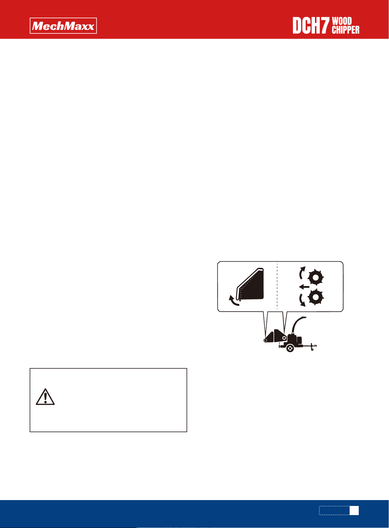
This label indicates the speed setting of the chipper. With
the throttle lever in the fast position (hare) the machine
is ready to chip. When the machine is not in use for short
periods of time move the lever to the idle position
(tortoise) or turn off completely. Move the lever to idle
position and turn off the choke, the engine will be
stopped.
STOPPING THE ROLLERS & ENGINE
ENGINE CONTROLS
BLADE WEAR
PETROL TANK INDICATOR
DAILY CHECKS BEFORE STARTING
BEFORE USING THE CHIPPER
Fuel filler
19
www.mechmaxx.com
Follow the instructions for a 'cold engine' but return the
choke to the off position as soon as the engine starts.
If engine fails to start after 10 seconds leave for 1 minute
and try again.
• Start the engine, test if the feed roller and its hydraulic
system can operate normally.
• To ensure the safety bar is always operational it must
be activated once before each work session. The rollers
will not function until the bar is activated. This proce-
dure must be repeated each time the ignition is
switched off.
• Check the emergency stop button as well
• Set engine to idle position.
• Allow to run for at least one full minute.
• Switch off and remove ignition key.
• Check that the chipper is running smoothly.
• Release the catches on the feed tray and lower.
• Stand to one side of the feed funnel.
• Proceed to feed material into the feed funnel.
Wood up to the recommended diameter can be fed into
the feed funnel. Put the butt end in first and engage it
with the feed rollers. The hydraulic feed rollers will pull the
branch into the machine quite quickly. Large diameter
material will have its feed rate automatically controlled
by the no stress unit.
Sometimes a piece of wood that is a particularly awkward
shape is too strong for the feed rollers to break. This will
cause the top roller to either bounce up and down on the
wood, or both rollers to stall. Pull the material out of the
feed funnel and trim it so the chipper can handle it.
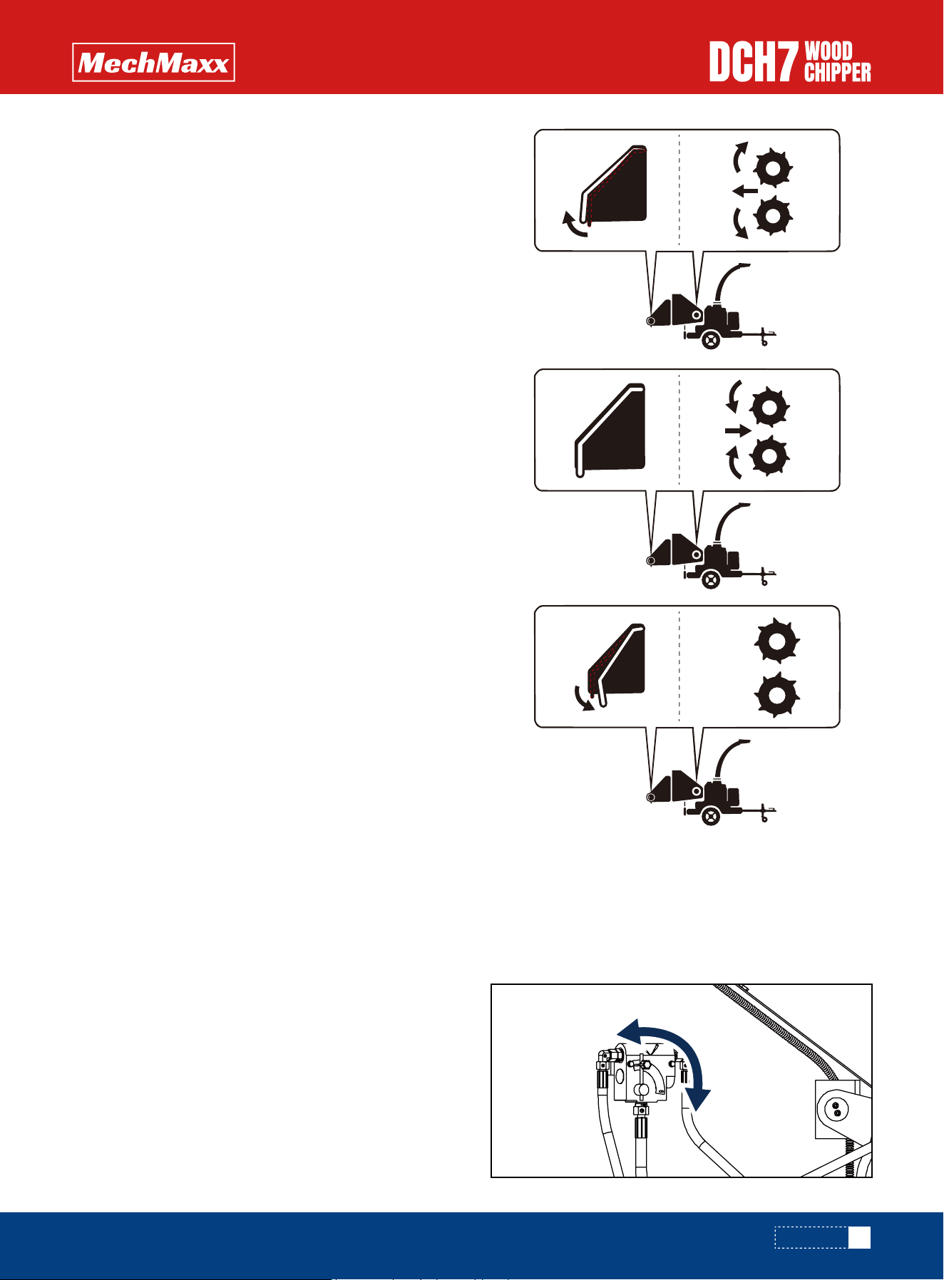
Both feed rollers should always turn at the same speed. If
one or both rollers stop or suddenly slow down it may be
that a piece of wood has become stuck behind one of the
rollers. If this occurs, adjust hydraulic directional control
valve to 'reverse feed' position, the rollers will turn
reverse and roll out the stuck wood, then you can adjust
the hydraulic directional control valve to "forward feed"
position, the chipper will work again. If this operation
doesn't work, pls push the EMERGENCY STOP BUTTON,
turn the engine off, remove the ignition key and investi-
gate.
Always be aware that what you are putting into the
chipper must come out. If the chips stop coming out of
the discharge tube but the chipper is taking material in -
STOP IMMEDIATELY.
Continuing to feed material into a blocked machine may
cause damage and will make it difficult to clear.
• Stop the engine and remove the ignition keys.
• Remove the discharge tube. Check that it is clear.
• Wearing gloves, reach into the rotor housing and scoop
out the majority of the debris causing the blockage.
If the chipper becomes blocked, proceed as follows:
• Place the throttle control at 1/3 throttle and pull the
choke out.
• Insert ignition key into starter switch.
• Turn the key to start the engine. Release the key as
soon as the engine starts.
• Gradually return the choke to the off position as the
engine starts and warms up. Allow the engine to warm
up for at least one minute before chipping.
FOR A COLD ENGINE:
FOR A WARM ENGINE:
For more detailed information refer to the Engine Owner's
Manual
DO NOT USE OR ATTEMPT TO START THE
CHIPPER WITHOUT THE PROTECTIVE
GUARDING AND DISCHARGE UNIT
SECURELY IN PLACE. FAILURE TO DO SO
MAY RESULT IN PERSONAL INJURY OR
LOSS OF LIFE.
STOPPING THE ENGINE
BLOCKAGES
STARTING TO CHIP
STARTING THE ENGINE
OPERATION
20
www.mechmaxx.com
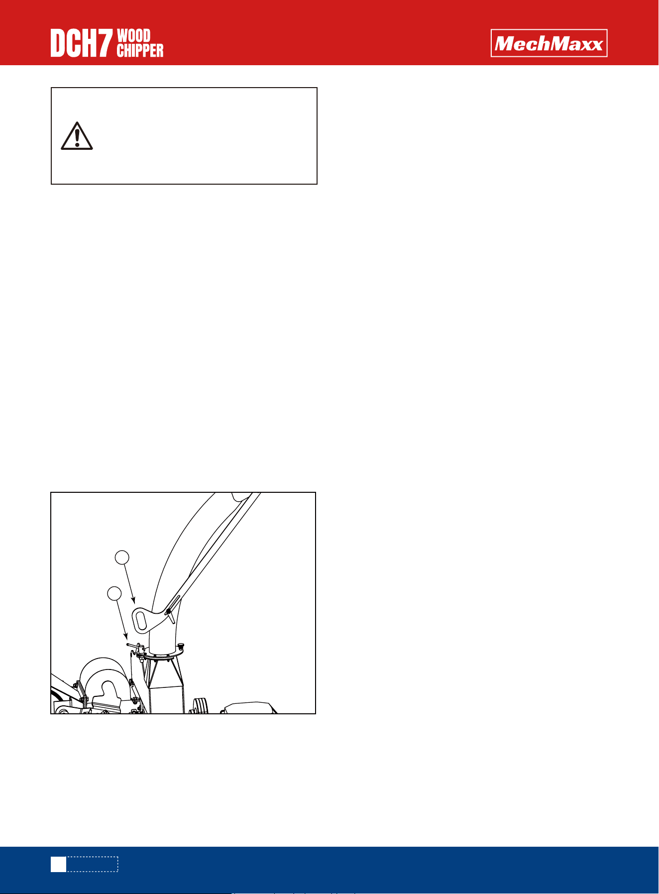
• Slacken nut using integral handle 1.
• Rotate to desired angle using handle 2.
• Retighten nut
• Replace the discharge tube.
• Restart the engine and increase to full speed.
• Allow machine time to clear excess chips still remain-
ing in rotor housing before you continue feeding brush-
wood. Feed in a small piece of wood while watching to
make sure that it comes out of the discharge. If this
does not clear it, repeat the process and carefully
inspect the discharge tube to find any obstruction.
NOTE: Continuing to feed the chipper with brushwood
once it has become blocked will cause the chipper to
compact the chips in the rotor housing and it will be
difficult and time consuming to clear.
Controlling the discharge is an essential part of safe
working.
DO NOT REACH INTO THE ROTOR HOUS-
ING WITH UNPROTECTED HANDS. THERE
ARE SHARP BLADES AND ANY SMALL
MOVEMENT OF THE ROTOR MAY CAUSE
SERIOUS INJURY.
DISCHARGE CONTROLS ROTATION
OPERATION
2
1
• Check ball head is well greased.
• Wind jockey wheel assembly anticlockwise until the
tow head is above the height of the ball hitch on the
vehicle.
• Reverse vehicle so the ball hitch is directly below the
tow head.
• Attach breakaway cable to a strong point on the
vehicle, not the ball hitch.
• Grasp handle on tow head and push back catch with
thumb.
• Wind jockey wheel assembly clockwise, to lower the
tow head onto the ball hitch.
• Release handle and continue to wind jockey wheel
clockwise. The tow head should snap into place on the
ball hitch. If it doesn't, repeat previous 2 steps.
• Wind jockey wheel up until fully retracted and the
jockey wheel frame is seated in its notch on the stem.
The chipper weight should be fully on the vehicle.
• Release jockey wheel clamp and slide the jockey wheel
assembly fully up.
• Tighten clamp on jockey wheel assembly.
• Connect electrical plug to socket on rear of towing
vehicle and check operation of all the trailer and vehicle
lights.
• Check the engine ignition switch is covered with the
plug provided.
• The chipper is now properly attached to the vehicle.
• Ensure the chipper will not roll away after being discon-
nected from the vehicle. Use the chocks provided if in
doubt.
• Disconnect the electrical cable from the vehicle socket.
• Release breakaway cable.
• Release the jockey wheel assembly clamp.
• Lower the jockey wheel assembly fully.
• Retighten the jockey wheel assembly clamp.
• Wind the jockey wheel assembly anticlockwise until it
starts to take the weight of the chipper.
• Grasp the handle and release the catch with your
thumb.
• Continue to wind the jockey wheel anticlockwise. This
should lift the tow head clear of the ball hitch.
• Drive the vehicle clear of the chipper.
• Wind the jockey wheel assembly to a suitable point
where the chipper is level.
• The chipper is now fully detached from the vehicle.
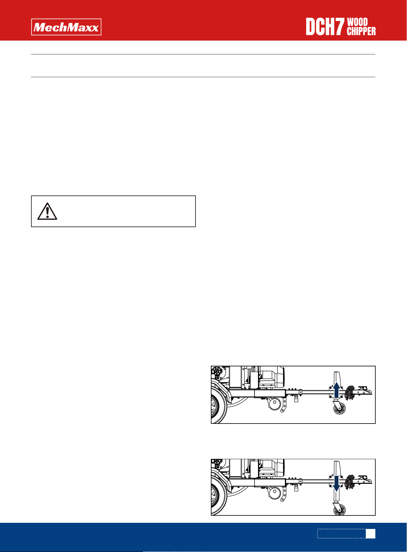
When hitched to a vehicle the prop stand and jockey
wheel should be stored in the towing position (a)
When the chipper is unhitched it should be secured before
starting work by using the wheel chocks and lowering the
prop stand and jockey wheel (b).
21
www.mechmaxx.com
• On rough or bumpy road surfaces reduce speed accord-
ingly to protect your machine from unnecessary vibra-
tion.
• When towing off road be aware of objects that may
catch the chipper undergear.
• When towing off road ensure inclination is not exces-
sive.
• Avoid excessively pot holed ground.
• When reversing the chipper the short wheel base will
react quickly to steering.
• Always check the discharge is tight before moving.
• Keep tyre pressures inflated to 2.2 bar or 32 psi.
• Check wheel nuts are tightened to 90nm or 65 lbs ft.
• Clear loose chippings and debris from the machine
before departing.
• Ensure feed funnel is closed and the catch is properly
engaged before departing.
DO NOT RIDE ON THE CHIPPER WHEN IT
IS BEING TOWED.
SAFE TRANSPORTATION
HITCHING ONTO THE TOW BALL
UNHITCHING THE CHIPPER
STABILISING THE CHIPPER
a
b
TRANSPORTATION
TRANSPORTATION
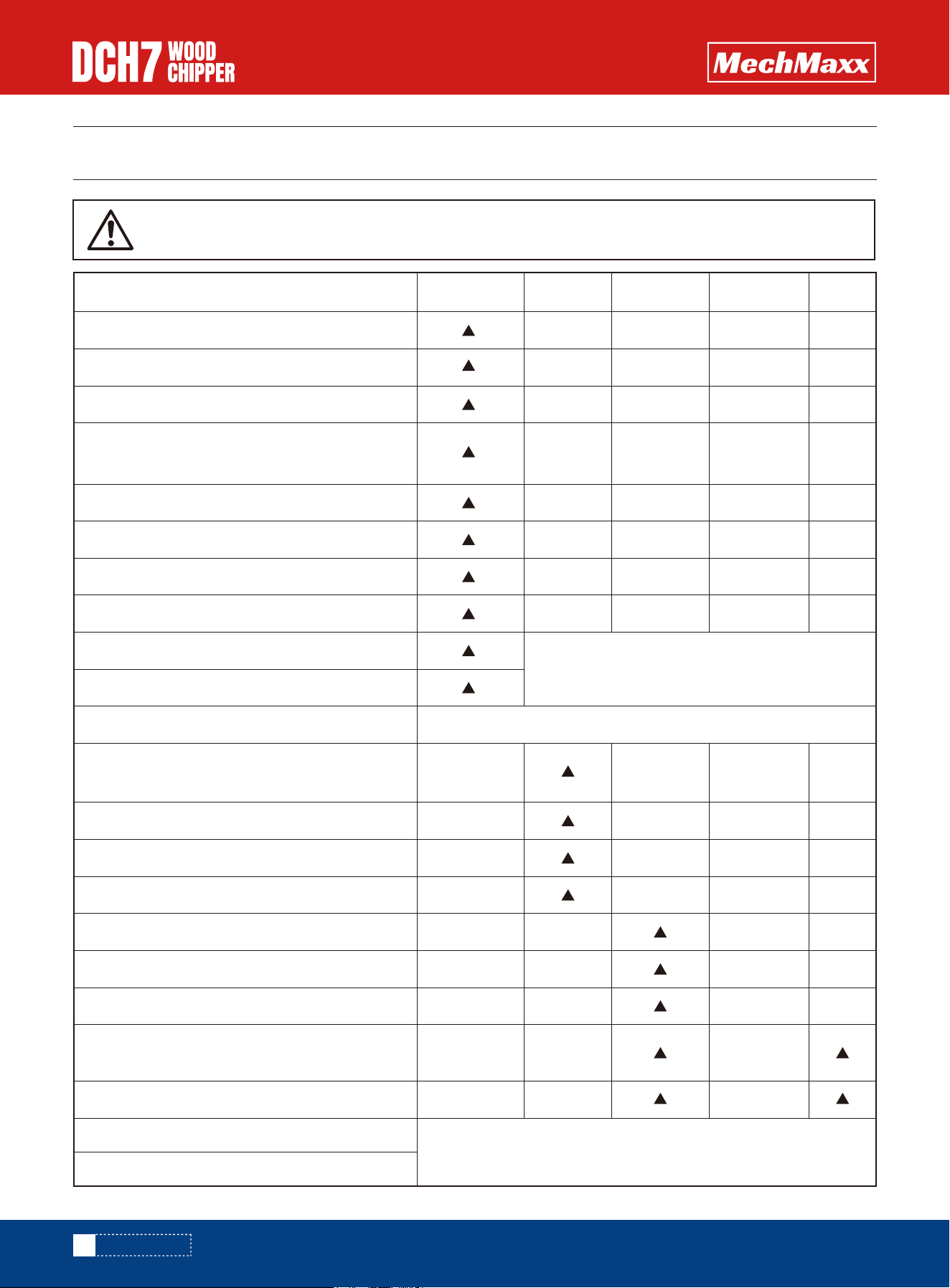
ALWAYS IMMOBILISE THE MACHINE BY STOPPING THE ENGINE, REMOVING THEIGNITION KEY
AND DISCONNECTING THE BATTERY BEFORE UNDERTAKING ANY MAINTENANCE WORK.
MAINTENANCE
Daily Check
Procedure
50 Hours 100 Hours 500 Hours 1 Year
Check engine oil - top up if necessary (10W-30).
Check for engine oil / hydraulic oil leaks.
Check fuel level.
Check feed funnel, feed roller cover, access covers,
engine covers and discharge unit are securely fitted.
Check blades
Ensure engine air intake is free from leaf build up.
Check tyre pressure is 2.2 Bar (32 psi).
Check safety bar mechanism.
DEPENDING ON WORKING ENVIRONMENT
OR AS REQUIRED - SEE PAGE 20
OR
OR
REFER TO YOUR ENGINE SUPPLIERS MANUAL
Grease the roller box slides.
Grease the roller spline and bearing.
Clean air filter element.
Grease discharge flange.
Check tension of main drive belts.
Check anvils for wear.
Check fuel pipes and clamp bands.
Check battery electrolyte level.
Replace hydraulic oil.
Replace fuel pipes and clamp bands.
Check spark plugs.
Check for loose electrical wiring.
Check for tightness all nuts, bolts and fastenings
making surenothing has worked loose.
Replace hydraulic oil filter every year or 100 hours
after service or repair work to the hydraulic system.
22
www.mechmaxx.com
MAINTENANCE

• Handle blades with extreme caution to avoid injury.-
Gloves should always be worn when handling the cutter
blades.
• THE drive belts should be connected while changing
blades, as this will restrict sudden movement of the
rotor.
• The major components of this machine are heavy.Lifting
equipment must be used for disassembly.
• CLEAN machines are safer and easier to service.
• Avoid contact with hydraulic oil.
• Remove the negative lead first and then the positive
lead.
• Clean, charge and/or top up the battery as required.
• Refitting is the reverse of removal. Apply a smear of
petroleum jelly to the terminals to prevent corrosion.
23
www.mechmaxx.com
NOTE: Your woodchipper is covered by a full 24 months
parts and labour warranty. Subject to correct mainte-
nance and proper machine usage, the bearings are
guaranteed for 24 months regardless of hours worked by
the machine. In conditions of 'heavy usage' - i.e. in excess
of 500 hours per year - it is recommended that the
bearings are changed annually to ensure that the machine
retains optimum working performance.
Only fit genuine replacement blades, screws and chipper
spares. Failure to do so will result in the invalidation of
the warranty and may result in damage to the chipper,
personal injury or even loss of life.
The HYDRAULIC WOOD CHIPPER is subject to large vibra-
tions during the normal course of operation. Consequently
there is always a possibility that nuts and bolts will work
themselves loose. It is important that periodic checks are
made to ensure the security of all fasteners. Fasteners
should be tightened using a torque wrench to the required
torque (see below). Uncalibrated torque wrenches can be
inaccurate by as much as 25%. It is therefore essential
that a calibrated torque wrench is used to achieve the
tightening torques listed below.
The blade bolts need to have thread glue applied to them.
ALWAYS IMMOBILISE THE ENGINE BEFORE UNDERTAKING
ANY MAINTENANCE WORK ON THE CHIPPER BY REMOVING
THE KEY AND DISCONNECTING THE BATTERY.
The lifting eye is designed to lift the machine's weight
only. Do not use hoist hook directly on the lifting eye, use
a correctly rated safety shackle. Inspect the lifting eye
prior to each use - DO NOT USE LIFTING EYE IF DAMAGED.
RETURN TO DEALER FOR ANVIL CHANGE
REFER TO SUPPLIERS INSTRUCTION SHEET
REFER TO YOUR ENGINE SUPPLIERS MANUAL
Daily Check
Procedure
50 hours 100 hours 500 hours 1 Year
Change engine oil.
Replace engine oil filter cartridge.
Check valve clearance.
Replace anvils when worn.
Axle maintenance.
Tow head maintenance.
Size Head Torque lb ft Torque Nm
Blade Bolts M16
M10
M10
M12
M8
24mm Hex
13 mm Hex
8 mmAllen Key
17 mm Hex
19 mm Hex
90
65
20
45
65
125
88
88
27
61
Anvil Bolts
General
General
General
SAFE MAINTENANCE
SAFE LIFTING OF THE CHIPPER
SPARES
CHECK FITTINGS
BATTERY REMOVAL AND MAINTENANCE
MAINTENANCE
• Batteries are filled with acid.
• Always store and transport batteries upright and
prevent from tilting so that no acid can escape.
• Store in a cool and dry place.
• Do not remove the protective cap from the positive
terminal.
• Run a FIFO (first in-first out) warehouse management
system.
• The batteries are filled with acid at a density of
1.28g/ml during the manufacturing process and are
ready for use.
• Recharge in case of insufficient starting power
• Switch off the engine and all electrical equipment.
• When removing, disconnect the negative terminal first.
• Avoid short circuits caused by tools, for example.
• Remove any foreign body from the battery tray, and
clamp battery tightly after installation.
• Clean the terminals and clamps, and lubricate slightly
with battery grease. When installing, first connect the
positive terminal, and check the terminal clamps for
tight fit.
• After having fitted the battery in the vehicle, remove the
protective cap from the positive terminal, and place it
on the terminal of the replaced battery in order to
prevent short circuits and possible sparks.
• Use parts from the replaced battery, such as the termi-
nal covers, elbows, vent pipe connection and terminal
holders (where applicable); use available or supplied
filler caps.
• Leave at least one vent open, otherwise there is a
danger of explosion. This also applies when old batter-
ies are returned.
WARNING NOTES: THE BATTERY CASE CAN
BECOME BRITTLE, TO AVOID THIS:
• Do not store batteries in direct sunlight.
• Discharged batteries may freeze up, therefore
store in an area free from frost.
• Dispose of old batteries at an authorised
collection point.
• The notes listed under item 1 are to be
followed for transport.
• Never dispose of old batteries in household
waste.
24
www.mechmaxx.com
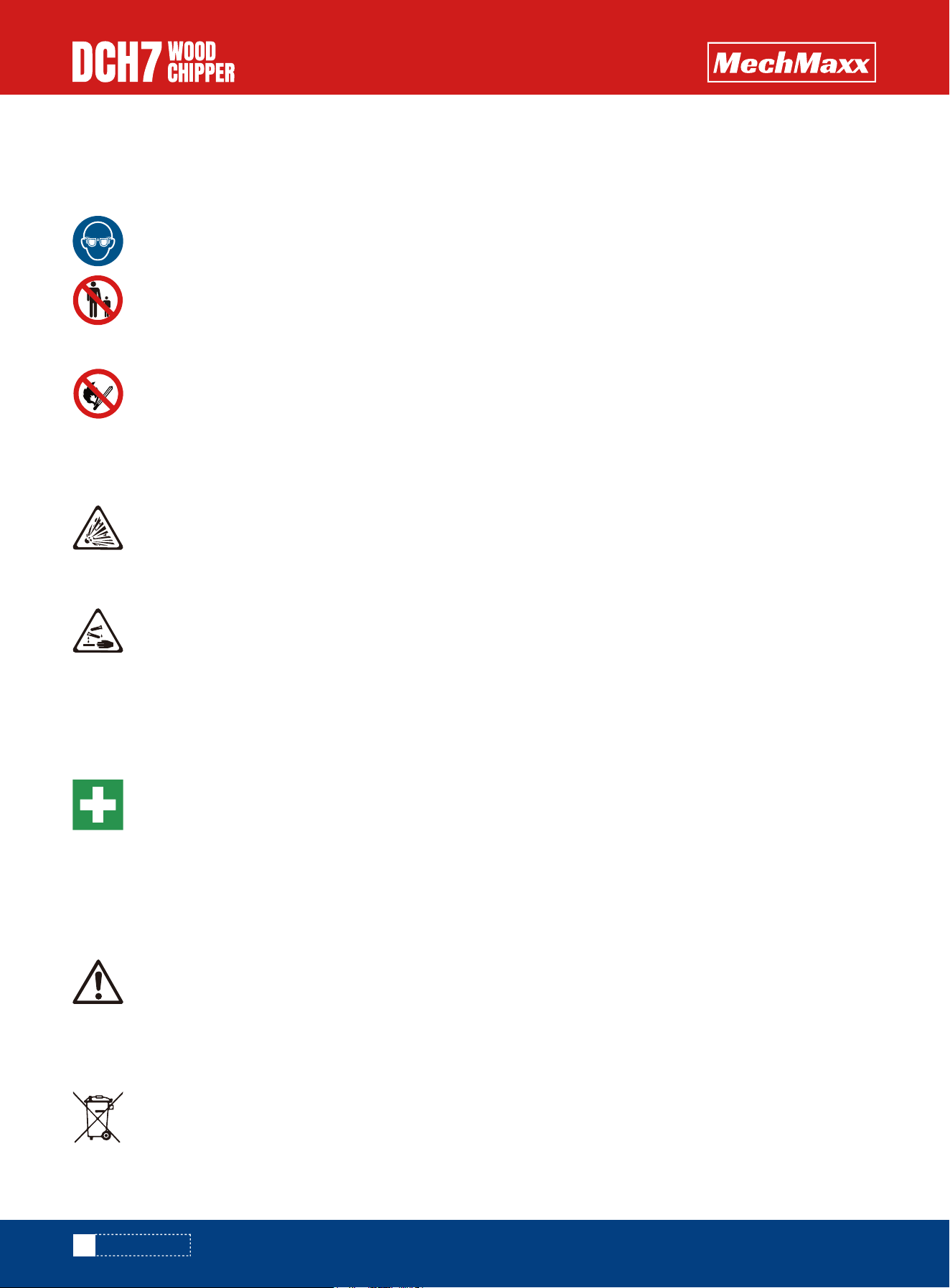
WARNING NOTES AND SAFETY REGULATIONS FOR FILLED
LEAD-ACID BATTERIES
EXPLOSION HAZARD
CORROSIVE HAZARD
FIRST AID
FIRST AID
For safety reasons, wear eye protection when
handling a battery.
• Fires, sparks, naked flames and smoking are
prohibited.
• Avoid causing sparks when dealing with cables
and electrical equipment, and beware of electro-
static discharges.
• Avoid short circuits.
A highly explosive oxyhydrogen gas mixture is
produced when batteries are charged.
Battery acid is highly corrosive, therefore:
• Wear protective gloves and eye protection.
• Do not tilt the battery, acid may escape from
the vent openings.
Rinse acid splashes in the eyes immediately for
several minutes with clear water. Remove
contact lenses if worn and continue rinsing.
Then, consult a doctor immediately.
Neutralize acid splashes on the skin or clothing
immediately with acid neutralizer (soda) or soap
suds, and rinse with plenty of water.
If acid is swallowed, consult a doctor immedi-
ately.
Keep out of reach of children.
BATTERY SAFETY INFORMATION STORAGE AND TRANSPORT
INITIAL OPERATION
CHARGING
INSTALLATION IN THE VEHICLE AND
REMOVAL FROM THE VEHICLE
• Remove the battery from the vehicle; disconnect the
lead of the negative terminal first.
• Ensure good ventilation.
• Use suitable direct current chargers only.
• Connect the positive terminal of the battery to the
positive output of the charger. Connect the negative
terminal accordingly.
MAINTENANCE
WEAR RIGGERS GLOVES FOR THE BLADE
CHANGING OPERATION.
MAINTENANCE
TAKING THE BATTERY OUT OF SERVICE
CHANGE BLADES
JUMP STARTING
25
www.mechmaxx.com
• Switch on the charger only after the battery has been
connected, and switch off the chargerfirst after
charging has been completed.
• Charging current-recommendation: 1/10 ampere of the
battery capacity Ah.
• Use a charger with a constant charging voltage of
14.4V for re-charging.
• If the acid temperature rises above 55° Celsius, stop
charging.
• The battery is fully charged when the charging voltage
has stopped rising for two hours.
• Charge the battery; store in a cool place or in the
vehicle with the negative terminal disconnected.
• Check the battery state of charge at regular intervals,
and correct by recharging when necessary
1. Turn the chipper off and remove the ignition keys.
2. Remove battery leads.
3. Remove the M10 bolt retaining the guard, allowing the
guard to be opened.
5. Turn rotor to blade change position.
6. Insert locking bar into rotor housing and rotor. Must
ensure that the opening time must longer than the time
when the moving parts stop. Before opening the housing
cover, pls see through the transparent cover to see if the
roller stopped.
7. Brush away all dirt and debris from the rotor and
blades.
8. With a 1inch spanner/socket undo the two nyloc nuts
and washers that are holding the blade in place. Remove
both blade bolts from the blade.
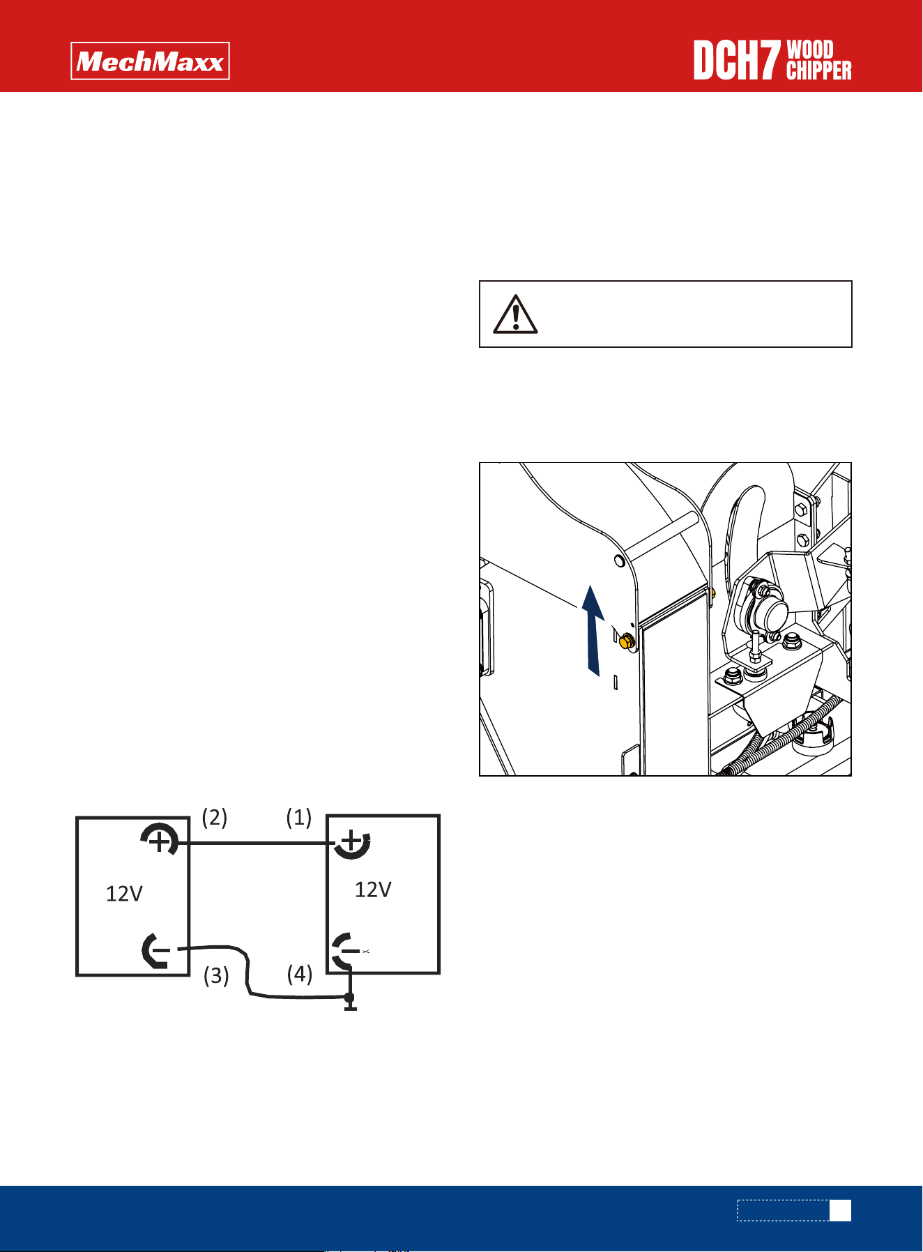
• Use the standardised jumper cable in compliance with
DIN 72553 only, and follow the operating instructions.
• Use batteries of the same nominal voltage only.
• Switch o� the engines of both vehicles.
• First connect the two positive terminals (1) and (2),
then connect the negative terminal of the charged
battery (3) to a metal part (4) of the vehicle requiring
assistance away from the battery.
• Start the engine of the vehicle providing assistance,
then start the engine of the vehicle requiring assis-
tance for a maximum of 15 seconds.
• Disconnect the cables in reverse sequence (4-3-2-1).
• Keep the battery clean and dry.
• Use a moist anti-static cloth only to wipe the battery,
otherwise there is a danger of explosion.
• Do not open the battery.
• Recharge in case of insufficient starting power
MAINTENANCE
TENSION BELTS
TENSION DRIVE BELTS
26
www.mechmaxx.com
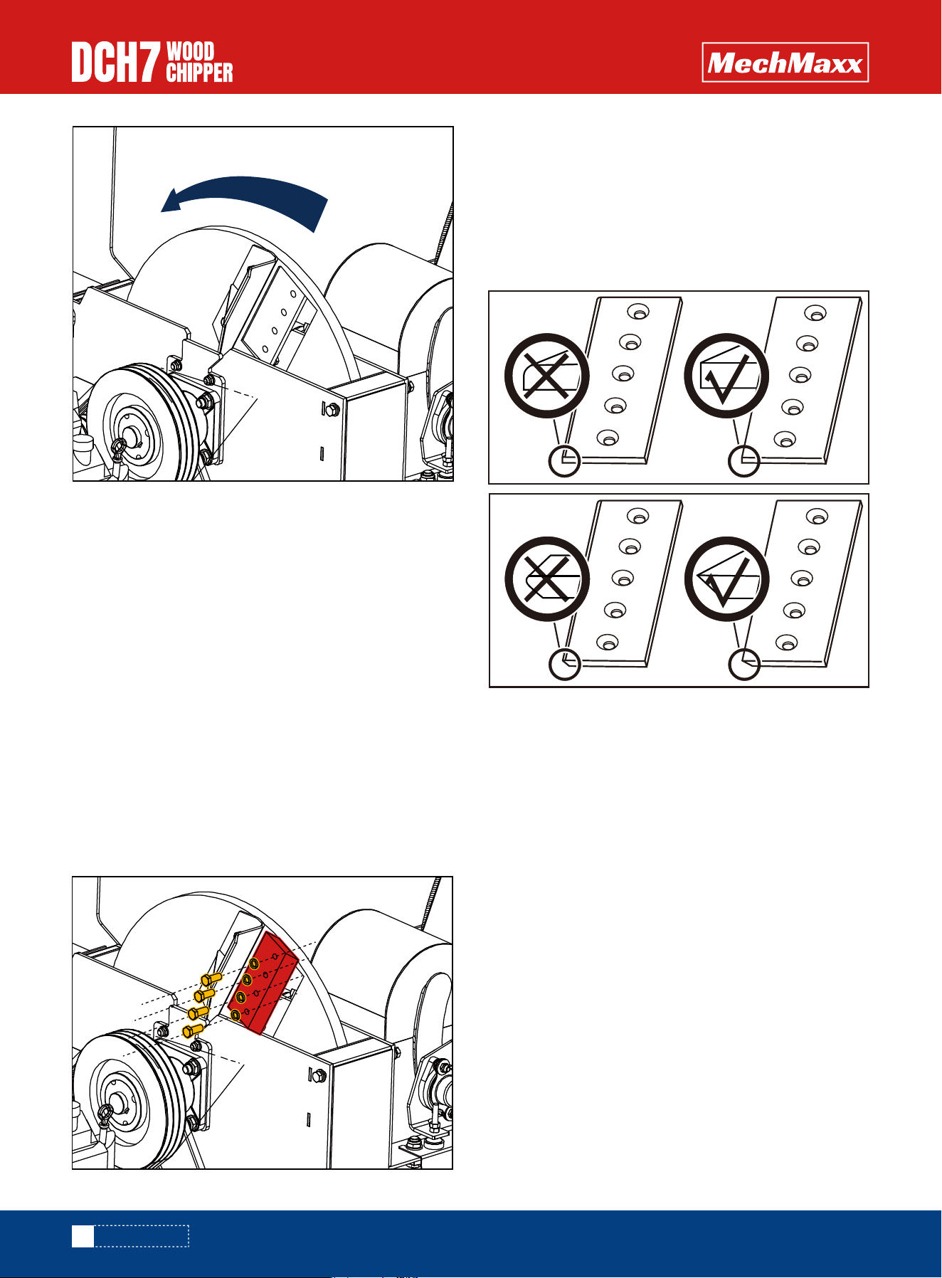
10. Withdraw the blade from the rotor.
11. Clean the back surface of the blade, blade bolts and
blade area of the rotor before reseating blades. The blades
must not have any material underneath them when tight-
ened. If they are not flat and tight they will become loose
very quickly.
12. Reassemble the blades, bolts, washers and nuts in
the order shown in the diagram above. Use only genuine
nuts and washers, as they are of a higher grade than
normally stocked at fastener factories. Failure to use the
appropriate grade nuts or washers may result in damage,
injury or death. The use of genuine blades and bolts is
recommended.
13. Apply a smear of anti seize compound (copper ease)
to the bolt threads and back face ofthe nuts. Do not apply
copper grease onto the counter bore faces ofthe blades
or bolts.
NOTE: There will normally be a rapid drop in tension during
run-in period for new belts. When new belts are fitted,
check the tension every 2 - 3 hours and adjust until the
tension remains constant.
1. Remove belt guard.
2. Loosen bolt in centre of tensioner pulley with a 0.74
inch spanner so that pulley is able to slide with minimal
wobble.
3. Turn nut in end of tensioner pulley slider until correct
belt tension is achieved. For instructions on checking
belt tension & correct belt tension values, please refer
to the V-Belt Tensioning Data Table.
4. Retighten bolt in centre of tensioner pulley.
5. Refit belt guard.
6. Run machine and test, recheck belt tension.
NOTE: Slack drive belts will cause poor performance and
excess belt and pulley wear.
ALWAYS SHARPEN BLADES ON A REGULAR BASIS. FAILURE
TO DO SO WILL CAUSE THE MACHINE TO UNDER PERFORM
AND WILL OVERLOAD ENGINE AND BEARINGS CAUSING
MACHINE BREAKDOWN. BLADES MUST NOT BE SHARP-
ENED BEYOND THE WEAR MARK (SEE DIAGRAM). FAILURE
TO COMPLY WITH THIS COULD RESULT IN MACHINE
DAMAGE, INJURY OR LOSS OF LIFE.
MAINTENANCE
27
www.mechmaxx.com
USE PLASTIC GLOVES TO KEEP OIL OFF
SKIN AND DISPOSE OF THE USED OIL AND
FILTERIN AN ECOLOGICALLY SOUND
WAY. THE OIL AND FILTER SHOULD BE
CHANGED ONCE AYEAR OR AT ANY TIME
IT BECOMES CONTAMINATED. BEFORE
STARTING CHECK THATTHE CHIPPER IS
STANDING LEVEL AND BRUSH AWAY
LOOSE CHIPS.
1. Remove belt guard.
2. Access the two nuts on the under side of the chassis
and slacken using a 0.74 inch socket spanner.
3. Adjust the M8 bolt on the outside plate until the desired
tension is achieved. For instructions on checking belt
tension & correct belt tension values, please refer to the
V-Belt Tensioning Data Table .
4. Retighten the two nuts to (88 Nm) 65 Ibs/ft.
5. Refit belt guard.
1. Remove the black screw cap from the top of the filter
housing.
2. Partially remove filter element from inner cup. Leave filter
to drain for 15 minutes.
3. Remove filter element from cup when clear of hydraulic oil.
4. Remove drain plug and drain oil into a suitable container.
5. Replace drain plug.
6. Refill with ISO VG 46 hydraulic oil until the level is between
the min and max lines on the tank (about 15 litres).
7. Refit the filter cup, install a new filter element and refit the
black screw cap, to the filter housing, ensuring o-ring
remains in place.
TENSION HYDRAULIC PUMP BELT
CHANGE HYDRAULIC OIL AND FILTER
MAINTENANCE
2
3
Hydraulic Oil
Filter
28
www.mechmaxx.com
All engine servicing must be performed in accordance with
the Engine Manufacturer's handbook provided with the
machine. FAILURE TO ADHERE TO THIS MAY INVALIDATE
WARRANTY AND/OR SHORTEN THE LIFE OF THE ENGINE.
This engine is certified to operate on unleaded gasoline with
a pump octane rating of 86 or higher (a research octane
rating of 91 or higher). Refuel in a well ventilated area with
the engine stopped. If the engine has been running, allow it
to cool first. Never refuel the engine inside a building where
gasoline fumes may reach flames or sparks. You may use
unleaded gasoline containing no more than 10% ethanol
(E10) or 5% methanol by volume. In addition, methanol must
contain cosolvents and corrosion inhibitors. Use of fuels
with content of ethanol or methanol greater than shown
above may cause starting and/or performance problems. It
may also damage metal, rubber, and plastic parts of the fuel
system. Engine damage or performance problems that
result from using a fuel with percentages of ethanol or meth-
anol greater than shown above are not covered under the
Warranty.
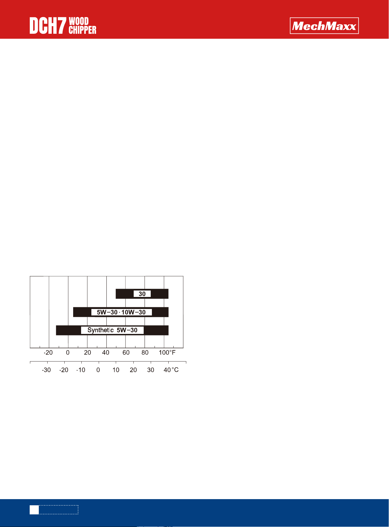
Use 4-stroke motor oil that meets or exceeds the require-
ments for APl service category SJ or later (or equivalent).
Always check the API service label on the oil container to be
sure it includes the letters SJ or later (or equivalent).
SAE 10W-30 or 5W-30 is recommended for general use. Use
a full synthetic 5W-30 for starting/operating temperatures
between 5°F (-15C) and-13°F (-25C). Other viscosities
shown in the chart may be used when the average tempera-
ture in your area is within the indicated range.
Recommended Fuel
All the hydraulic hoses should be regularly inspected for
chafing and leaks. The hydraulic system is pressurized to
150 Bar and thus the equipment containing it must be kept
in good condition.
Identify the hoses that run to the top motor. These have the
highest chance of damage as they are constantly moving. If
any hydraulic components are changed new seals should be
installed during reassembly. Fittings should then be retight-
ened.
ENGINE SERVICING
REFUELING
RECOMMENDED OIL
CHECK HOSES
MAINTENANCE
AMBIENT TEMPERATURE

29
www.mechmaxx.com
TROUBLESHOOTING
TROUBLESHOOTING
Remedy
Problem
Cause
Engine fails to start 1. Spark plug wire is disconnected.
2. Out of fuel or stale fuel.
3. Engine and/or Fuel valve is not in
ON position.
4. Choke lever is not in CLOSE position.
5. Blocked fuel line.
6. Fouled spark plug.
7. Engine flooding.
1. Attach spark plug wire securely to
spark plug.
2. Fill with clean, fresh gasoline.
3. Engine and Fuel valve must be in ON
position.
4. Choke lever must be in CLOSE position
for a cold start.
5. Clean fuel line.
6. Clean, adjust gap, or replace.
7. Wait a few minutes to restart, but do
not prime.
Engine runs erratically
1. Connect and tighten spark plug wire.
2. Move choke lever to OPEN position.
3. Clean fuel line. Fill tank with clean,
fresh gasoline.
4. Clear vent.
5. Drain fuel tank. Refill with fresh fuel.
6. Clean or replace air cleaner.
7. Refer to engine manual.
1. Spark plug wire is loose.
2. Unit running with Choke lever in
CLOSE position.
3. Blocked fuel line or stale fuel.
4. Vent plugged.
5. Water or dirt in fuel system.
6. Dirty air cleaner.
7. Improper carburetor adjustment.
Engine overheats 1. Fill crankcase with proper oil.
2. Clean air cleaner.
3. Remove housing and clean.
4. Refer to engine manual.
1. Engine oil level low.
2. Dirty air cleaner.
3. Air flow restricted.
4. Carburetor not adjusted properly.
Chipping action seems
too slow, cutting disk
stalls, or no material
is discharged when
engine is running
1. Run the engine at full throttle.
2. Tighten or replace drive belt.
3. Sharpen or replace knives.
4. Remove any built-up debris and turn
cutting disk with a wooden stick to be
sure it turns freely.
5. Clean out debris.
1. Engine speed is too slow causing
belt to slip.
2. Drive Belt is loose or damaged.
3. Knives are dull or damaged.
4. Cutting disk is jammed by
debris from the feed hopper and
discharge chute.
5. Discharge chute is clogged.

30
www.mechmaxx.com
TROUBLESHOOTING
Remedy
Problem
Cause
The belt frays or rolls
over the pulley
When chipping,
branch seems to
vibrate and move
about excessively with
unusual noise
Chipper Knives are
hitting the wear plate
The machine's wheels
track left or right
while being towed
Low tire pressure.
The gap between the knives and wear
plate is set incorrectly.
Add air to tires.
Adjust the gap.
1.Sharpen or replace knives.
2. Loosen the knife mounting screws, reset
the knives, and tighten the screws.
3. Adjust the gap.
4. Allow unit to clear itself before adding
more material to the hopper.
1. Check drive belts for wear and hard
spots. File off any nicks on the pulley.
2. Replace drive belts.
3. Adjust pulleys.
1. Rotor drive pulley groove may be
nicked.
2. Drive belts may be stretched.
3. Pulleys may be misaligned.
1. Knives are dull or damaged.
2. Knives are not properly seated on
the cutting disk.
3. The gap between the knives and
wear plate is too large.
4. Rotor is overloaded with material.