
INSTRUCTION MANUAL
MANUAL DE INSTRUCCIONES
Cordless Combination Hammer
Martillo Rotativo Combinado
Inalámbrico
GRH10
IMPORTANT: Read Before Using.
IMPORTANTE: Lea antes de usar.

2 ENGLISH
ENGLISH (Original instructions)
SPECIFICATIONS
Model: GRH10
Capacities Concrete 20 mm (13/16")
Core bit 35 mm (1-3/8")
Diamond core bit (dry type) 32 mm (1-1/4")
Steel 13 mm (1/2")
Wood 26 mm (1")
No load speed 0 - 1,350 /min
Blows per minute 0 - 5,000 /min
Overall length (with BL4025) 289 mm (11-3/8")
Rated voltage D.C. 36 V - 40 V max
Net weight 2.8 - 4.5 kg (6.2 - 9.9 lbs)
Optional accessory
Model: DX16
Suction performance 0.24 l/min
Operating stroke Up to 105 mm (4-1/8")
Suitable drill bit Up to 165 mm (6-1/2")
Net weight 0.77 kg (1.7 lbs)
• Duetoourcontinuingprogramofresearchanddevelopment,thespecicationshereinaresubjecttochange
without notice.
• Specicationsmaydierfromcountrytocountry.
• Theweightmaydierdependingontheattachment(s),includingthebatterycartridge.Thelightestandheavi-
est combinations, according to EPTA-Procedure 01/2014, are shown in the table.
Applicable battery cartridge and charger
Battery cartridge BL4020* / BL4025* / BL4040* / BL4050F / BL4080F
* : Recommended battery
Charger DC40RA / DC40RB / DC40RC
• Some of the battery cartridges and chargers listed above may not be available depending on your region of
residence.
WARNING: Only use the battery cartridges and chargers listed above. Use of any other battery cartridges
andchargersmaycauseinjuryand/orre.
Recommended cord connected power source
Portable power pack PDC01 / PDC1200
• The cord connected power source(s) listed above may not be available depending on your region of residence.
• Before using the cord connected power source, read instruction and cautionary markings on them.

3 ENGLISH
SAFETY WARNINGS
General power tool safety warnings
WARNING Read all safety warnings, instructions,
illustrations and specications provided with this
power tool. Failure to follow all instructions listed below
mayresultinelectricshock,reand/orseriousinjury.
Save all warnings and instruc-
tions for future reference.
The term "power tool" in the warnings refers to your
mains-operated (corded) power tool or battery-operated
(cordless) power tool.
Work area safety
1. Keep work area clean and well lit. Cluttered or
dark areas invite accidents.
2. Do not operate power tools in explosive atmo-
spheres, such as in the presence of ammable
liquids, gases or dust. Power tools create sparks
which may ignite the dust or fumes.
3. Keep children and bystanders away while
operating a power tool. Distractions can cause
you to lose control.
Electrical safety
1. Power tool plugs must match the outlet. Never
modify the plug in any way. Do not use any
adapter plugs with earthed (grounded) power
tools. Unmodiedplugsandmatchingoutletswill
reduce risk of electric shock.
2. Avoid body contact with earthed or grounded
surfaces, such as pipes, radiators, ranges and
refrigerators. There is an increased risk of elec-
tric shock if your body is earthed or grounded.
3. Do not expose power tools to rain or wet con-
ditions. Water entering a power tool will increase
the risk of electric shock.
4. Do not abuse the cord. Never use the cord for
carrying, pulling or unplugging the power tool.
Keep cord away from heat, oil, sharp edges
or moving parts. Damaged or entangled cords
increase the risk of electric shock.
5. When operating a power tool outdoors, use an
extension cord suitable for outdoor use. Use of
a cord suitable for outdoor use reduces the risk of
electric shock.
6. If operating a power tool in a damp location is
unavoidable, use a ground fault circuit inter-
rupter (GFCI) protected supply. Use of a GFCI
reduces the risk of electric shock.
7.
Power tools can produce electromagnetic elds
(EMF) that are not harmful to the user. However,
users of pacemakers and other similar medical
devices should contact the maker of their device and/
or doctor for advice before operating this power tool.
Personal safety
1. Stay alert, watch what you are doing and use
common sense when operating a power tool.
Do not use a power tool while you are tired or
under the inuence of drugs, alcohol or med-
ication. A moment of inattention while operating
powertoolsmayresultinseriouspersonalinjury.
2. Use personal protective equipment. Always
wear eye protection. Protective equipment such
as a dust mask, non-skid safety shoes, hard hat or
hearing protection used for appropriate conditions
willreducepersonalinjuries.
3. Prevent unintentional starting. Ensure the
switch is in the o-position before connecting
to power source and/or battery pack, picking
up or carrying the tool. Carrying power tools with
yourngerontheswitchorenergisingpowertools
that have the switch on invites accidents.
4. Remove any adjusting key or wrench before
turning the power tool on. A wrench or a key left
attached to a rotating part of the power tool may
resultinpersonalinjury.
5. Do not overreach. Keep proper footing and
balance at all times. This enables better control
of the power tool in unexpected situations.
6. Dress properly. Do not wear loose clothing or
jewellery. Keep your hair and clothing away
from moving parts.Looseclothes,jewelleryor
long hair can be caught in moving parts.
7. If devices are provided for the connection of
dust extraction and collection facilities, ensure
these are connected and properly used. Use of
dust collection can reduce dust-related hazards.
8.
Do not let familiarity gained from frequent use
of tools allow you to become complacent and
ignore tool safety principles. A careless action can
causesevereinjurywithinafractionofasecond.
9. Always wear protective goggles to protect
your eyes from injury when using power tools.
The goggles must comply with ANSI Z87.1 in
the USA.
It is an employer's responsibility to enforce the
use of appropriate safety protective equipment
by the tool operators and by other persons in
the immediate working area.
Power tool use and care
1. Do not force the power tool. Use the correct
power tool for your application. The correct
powertoolwilldothejobbetterandsaferatthe
rate for which it was designed.
2. Do not use the power tool if the switch does
not turn it on and o. Any power tool that cannot
be controlled with the switch is dangerous and
must be repaired.
3. Disconnect the plug from the power source
and/or remove the battery pack, if detachable,
from the power tool before making any adjust-
ments, changing accessories, or storing power
tools. Such preventive safety measures reduce
the risk of starting the power tool accidentally.
4. Store idle power tools out of the reach of chil-
dren and do not allow persons unfamiliar with
the power tool or these instructions to operate
the power tool. Power tools are dangerous in the
hands of untrained users.
5. Maintain power tools and accessories. Check
for misalignment or binding of moving parts,
breakage of parts and any other condition that
may aect the power tool’s operation. If dam-
aged, have the power tool repaired before use.
Many accidents are caused by poorly maintained
power tools.

4 ENGLISH
6. Keep cutting tools sharp and clean. Properly
maintained cutting tools with sharp cutting edges
are less likely to bind and are easier to control.
7. Use the power tool, accessories and tool bits
etc. in accordance with these instructions, tak-
ing into account the working conditions and
the work to be performed. Use of the power tool
foroperationsdierentfromthoseintendedcould
result in a hazardous situation.
8. Keep handles and grasping surfaces dry,
clean and free from oil and grease. Slippery
handles and grasping surfaces do not allow for
safe handling and control of the tool in unexpected
situations.
9. When using the tool, do not wear cloth work
gloves which may be entangled. The entangle-
ment of cloth work gloves in the moving parts may
resultinpersonalinjury.
Battery tool use and care
1. Recharge only with the charger specied by
the manufacturer. A charger that is suitable for
onetypeofbatterypackmaycreateariskofre
when used with another battery pack.
2. Use power tools only with specically desig-
nated battery packs. Use of any other battery
packsmaycreateariskofinjuryandre.
3. When battery pack is not in use, keep it away
from other metal objects, like paper clips,
coins, keys, nails, screws or other small metal
objects, that can make a connection from one
terminal to another. Shorting the battery termi-
nalstogethermaycauseburnsorare.
4. Under abusive conditions, liquid may be
ejected from the battery; avoid contact. If con-
tact accidentally occurs, ush with water. If
liquid contacts eyes, additionally seek medical
help.Liquidejectedfromthebatterymaycause
irritation or burns.
5. Do not use a battery pack or tool that is dam-
aged or modied.Damagedormodiedbatteries
may exhibit unpredictable behaviour resulting in
re,explosionorriskofinjury.
6. Do not expose a battery pack or tool to re or
excessive temperature.Exposuretoreortem-
perature above 130 °C may cause explosion.
7. Follow all charging instructions and do not
charge the battery pack or tool outside the
temperature range specied in the instruc-
tions. Charging improperly or at temperatures
outsidethespeciedrangemaydamagethe
batteryandincreasetheriskofre.
Service
1. Have your power tool serviced by a qualied
repair person using only identical replacement
parts. This will ensure that the safety of the power
tool is maintained.
2. Never service damaged battery packs. Service
of battery packs should only be performed by the
manufacturer or authorized service providers.
3. Follow instruction for lubricating and chang-
ing accessories.
4. Do not modify or attempt to repair the appli-
ance or the battery pack except as indicated in
the instructions for use and care.
CORDLESS ROTARY HAMMER
SAFETY WARNINGS
1. Wear ear protectors. Exposure to noise can
cause hearing loss.
2. Use auxiliary handle(s), if supplied with the
tool.Lossofcontrolcancausepersonalinjury.
3. Hold power tool by insulated gripping sur-
faces, when performing an operation where
the cutting accessory may contact hidden
wiring. Cutting accessory contacting a "live"
wire may make exposed metal parts of the power
tool "live" and could give the operator an electric
shock.
4. Wear a hard hat (safety helmet), safety glasses
and/or face shield. Ordinary eye or sun glasses
are NOT safety glasses. It is also highly recom-
mended that you wear a dust mask and thickly
padded gloves.
5. Be sure the bit is secured in place before
operation.
6. Under normal operation, the tool is designed
to produce vibration. The screws can come
loose easily, causing a breakdown or accident.
Check tightness of screws carefully before
operation.
7. In cold weather or when the tool has not been
used for a long time, let the tool warm up for
a while by operating it under no load. This
will loosen up the lubrication. Without proper
warm-up, hammering operation is dicult.
8. Always be sure you have a rm footing. Be
sure no one is below when using the tool in
high locations.
9. Hold the tool rmly with both hands.
10. Keep hands away from moving parts.
11. Do not leave the tool running. Operate the tool
only when hand-held.
12. Do not point the tool at any one in the area
when operating. The bit could y out and
injure someone seriously.
13. Do not touch the bit, parts close to the bit, or
workpiece immediately after operation; they
may be extremely hot and could burn your
skin.
14. Some material contains chemicals which may
be toxic. Take caution to prevent dust inhala-
tion and skin contact. Follow material supplier
safety data.
15. Always be sure that the tool is switched
o and the battery cartridge and the bit are
removed before handing the tool to other
person.
16. Before operation, make sure that there is no
buried object such as electric pipe, water pipe
or gas pipe in the working area. Otherwise, the
drill bit/chisel may touch them, resulting an electric
shock, electrical leakage or gas leak.
17. Do not operate the tool at no-load
unnecessarily.
SAVE THESE INSTRUCTIONS.
5 ENGLISH
WARNING: DO NOT let comfort or familiarity
with product (gained from repeated use) replace
strict adherence to safety rules for the subject
product. MISUSE or failure to follow the safety
rules stated in this instruction manual may cause
serious personal injury.
Symbols
The followings show the symbols used for tool.
volts
direct current
no load speed
revolutions or reciprocation per minute
number of blow
diameter
FCC statement
This device complies with part 15 of the FCC Rules.
Operationissubjecttothefollowingtwoconditions:(1)
This device may not cause harmful interference, and (2)
this device must accept any interference received, includ-
ing interference that may cause undesired operation.
NOTE: This equipment has been tested and found
to comply with the limits for a Class B digital device,
pursuant to part 15 of the FCC Rules. These limits are
designed to provide reasonable protection against
harmful interference in a residential installation. This
equipment generates, uses and can radiate radio
frequency energy and, if not installed and used in
accordance with the instructions, may cause harmful
interference to radio communications. However, there is
no guarantee that interference will not occur in a partic-
ular installation. If this equipment does cause harmful
interference to radio or television reception, which can
bedeterminedbyturningtheequipmentoandon,the
user is encouraged to try to correct the interference by
one or more of the following measures:
— Reorient or relocate the receiving antenna.
— Increase the separation between the equipment
and receiver.
—
Connect the equipment into an outlet on a circuit dif-
ferent from that to which the receiver is connected.
— Consult the dealer or an experienced radio/TV
technician for help.
FCC CAUTION
Changesormodicationsnotexpresslyapprovedby
the party responsible for compliance could void the
user’s authority to operate the equipment.
Makita U.S.A. Inc.
14930 Northam Street, La Mirada, CA 90638-5753, USA
+1-(714) 522-8088
Important safety instructions for
battery cartridge
1. Before using battery cartridge, read all instruc-
tions and cautionary markings on (1) battery
charger, (2) battery, and (3) product using
battery.
2. Do not disassemble or tamper with the battery
cartridge.Itmayresultinare,excessiveheat,
or explosion.
3. If operating time has become excessively
shorter, stop operating immediately. It may
result in a risk of overheating, possible burns
and even an explosion.
4. If electrolyte gets into your eyes, rinse them
out with clear water and seek medical atten-
tion right away. It may result in loss of your
eyesight.
5. Do not short the battery cartridge:
(1) Do not touch the terminals with any con-
ductive material.
(2) Avoid storing battery cartridge in a con-
tainer with other metal objects such as
nails, coins, etc.
(3) Do not expose battery cartridge to water
or rain.
A battery short can cause a large current
ow, overheating, possible burns and even a
breakdown.
6. Do not store and use the tool and battery car-
tridge in locations where the temperature may
reach or exceed 50 °C (122 °F).
7. Do not incinerate the battery cartridge even if
it is severely damaged or is completely worn
out. The battery cartridge can explode in a re.
8. Do not nail, cut, crush, throw, drop the battery
cartridge, or hit against a hard object to the
battery cartridge. Such conduct may result in a
re,excessiveheat,orexplosion.
9. Do not use a damaged battery.
10. The contained lithium-ion batteries are subject
to the Dangerous Goods Legislation require-
ments.
For commercial transports e.g. by third parties,
forwarding agents, special requirement on pack-
aging and labeling must be observed.
For preparation of the item being shipped, consult-
ing an expert for hazardous material is required.
Please also observe possibly more detailed
national regulations.
Tapeormaskoopencontactsandpackupthe
battery in such a manner that it cannot move
around in the packaging.
11. When disposing the battery cartridge, remove
it from the tool and dispose of it in a safe
place. Follow your local regulations relating to
disposal of battery.
12. Use the batteries only with the products
specied by Makita. Installing the batteries to
non-compliantproductsmayresultinare,exces-
sive heat, explosion, or leak of electrolyte.
13. If the tool is not used for a long period of time,
the battery must be removed from the tool.

6 ENGLISH
14. During and after use, the battery cartridge may
take on heat which can cause burns or low
temperature burns. Pay attention to the han-
dling of hot battery cartridges.
15. Do not touch the terminal of the tool imme-
diately after use as it may get hot enough to
cause burns.
16. Do not allow chips, dust, or soil stuck into the
terminals, holes, and grooves of the battery
cartridge.Itmaycauseheating,catchingre,
burst and malfunction of the tool or battery car-
tridge,resultinginburnsorpersonalinjury.
17. Unless the tool supports the use near
high-voltage electrical power lines, do not use
the battery cartridge near high-voltage electri-
cal power lines. It may result in a malfunction or
breakdown of the tool or battery cartridge.
18. Keep the battery away from children.
SAVE THESE INSTRUCTIONS.
CAUTION: Only use genuine Makita batteries.
Use of non-genuine Makita batteries, or batteries that
have been altered, may result in the battery bursting
causingres,personalinjuryanddamage.Itwill
also void the Makita warranty for the Makita tool and
charger.
Tips for maintaining maximum
battery life
1. Charge the battery cartridge before completely
discharged. Always stop tool operation and
charge the battery cartridge when you notice
less tool power.
2. Never recharge a fully charged battery car-
tridge. Overcharging shortens the battery
service life.
3. Charge the battery cartridge with room tem-
perature at 10 °C - 40 °C (50 °F - 104 °F). Let
a hot battery cartridge cool down before
charging it.
4. When not using the battery cartridge, remove
it from the tool or the charger.
5. Charge the battery cartridge if you do not use
it for a long period (more than six months).
Important safety instructions for
wireless unit
1. Do not disassemble or tamper with the wire-
less unit.
2. Keep the wireless unit away from young chil-
dren. If accidentally swallowed, seek medical
attention immediately.
3. Use the wireless unit only with Makita tools.
4. Do not expose the wireless unit to rain or wet
conditions.
5. Do not use the wireless unit in places where
the temperature exceeds 50 °C (122 °F).
6. Do not operate the wireless unit in places
where medical instruments, such as heart
pace makers are nearby.
7. Do not operate the wireless unit in places
where automated devices are nearby. If oper-
ated, automated devices may develop malfunction
or error.
8. Do not operate the wireless unit in places
under high temperature or places where
static electricity or electrical noise could be
generated.
9. The wireless unit can produce electromagnetic
elds (EMF) but they are not harmful to the
user.
10. The wireless unit is an accurate instrument. Be
careful not to drop or strike the wireless unit.
11. Avoid touching the terminal of the wireless
unit with bare hands or metallic materials.
12. Always remove the battery on the product
when installing the wireless unit into it.
13. When opening the lid of the slot, avoid the
place where dust and water may come into the
slot. Always keep the inlet of the slot clean.
14. Always insert the wireless unit in the correct
direction.
15. Do not press the wireless activation button
on the wireless unit too hard and/or press the
button with an object with a sharp edge.
16. Always close the lid of the slot when
operating.
17. Do not remove the wireless unit from the slot
while the power is being supplied to the tool.
Doing so may cause a malfunction of the wireless
unit.
18. Do not remove the sticker on the wireless unit.
19. Do not put any sticker on the wireless unit.
20. Do not leave the wireless unit in a place where
static electricity or electrical noise could be
generated.
21. Do not leave the wireless unit in a place sub-
ject to high heat, such as a car sitting in the
sun.
22. Do not leave the wireless unit in a dusty or
powdery place or in a place corrosive gas
could be generated.
23. Sudden change of the temperature may bedew
the wireless unit. Do not use the wireless unit
until the dew is completely dried.
24. When cleaning the wireless unit, gently wipe
with a dry soft cloth. Do not use benzine, thin-
ner, conductive grease or the like.
25. When storing the wireless unit, keep it in the
supplied case or a static-free container.
26. Do not insert any devices other than Makita
wireless unit into the slot on the tool.
27. Do not use the tool with the lid of the slot dam-
aged. Water, dust, and dirt come into the slot may
cause malfunction.
28. Do not pull and/or twist the lid of the slot more
than necessary.Restorethelidifitcomeso
from the tool.
29. Replace the lid of the slot if it is lost or
damaged.
SAVE THESE INSTRUCTIONS.
7 ENGLISH
FUNCTIONAL
DESCRIPTION
CAUTION: Always be sure that the tool is
switched o and the battery cartridge is removed
before adjusting or checking function on the tool.
Installing or removing battery
cartridge
CAUTION: Always switch o the tool before
installing or removing of the battery cartridge.
CAUTION: Hold the tool and the battery car-
tridge rmly when installing or removing battery
cartridge. Failure to hold the tool and the battery
cartridgermlymaycausethemtoslipoyourhands
and result in damage to the tool and battery cartridge
andapersonalinjury.
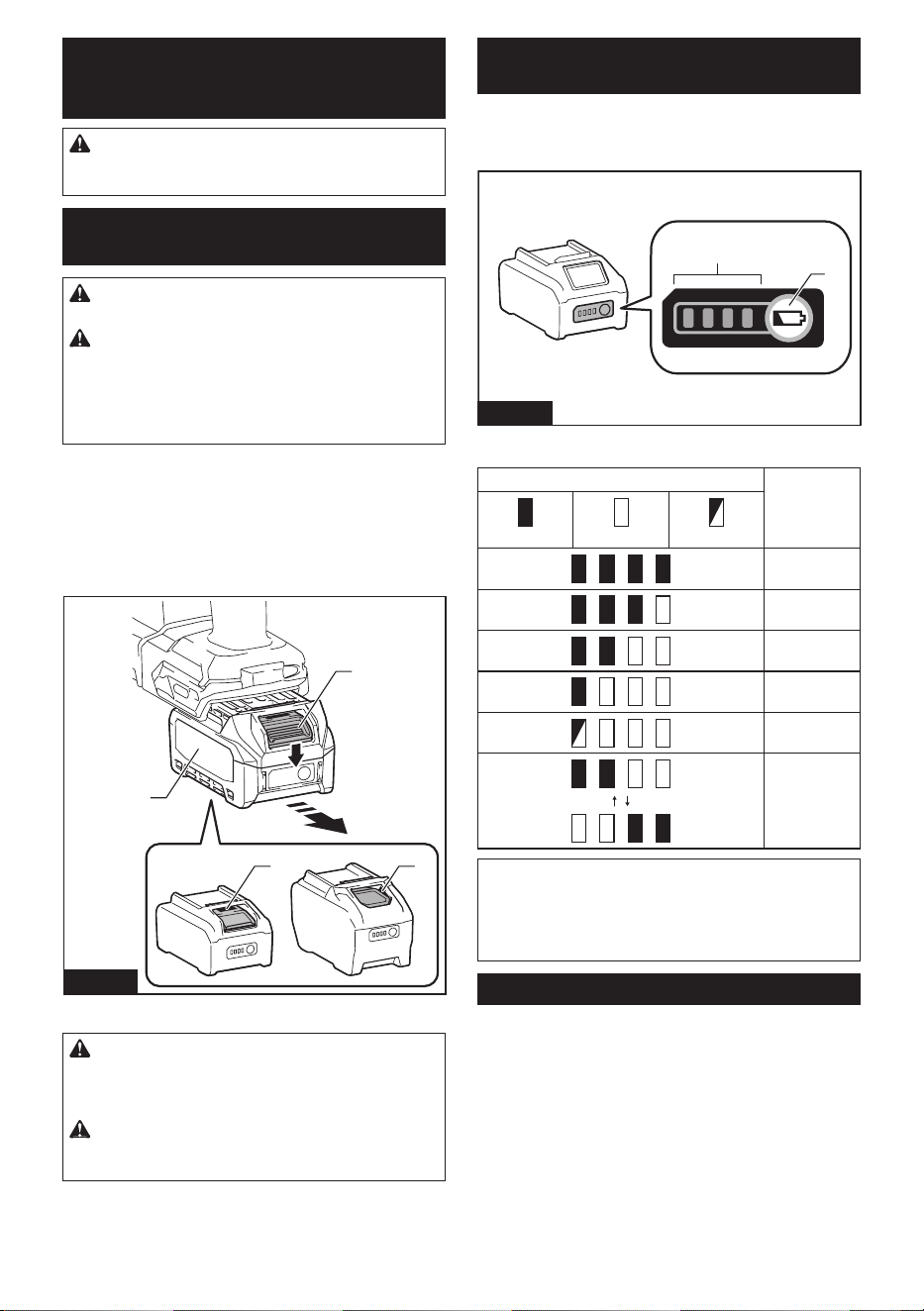
To install the battery cartridge, align the tongue on the
battery cartridge with the groove in the housing and slip
it into place. Insert it all the way until it locks in place
with a little click. If you can see the red indicator as
showninthegure,itisnotlockedcompletely.
To remove the battery cartridge, slide it from the tool
while sliding the button on the front of the cartridge.
11
2
3
Fig.1
►1. Red indicator 2. Button 3. Battery cartridge
CAUTION: Always install the battery cartridge
fully until the red indicator cannot be seen. If not,
itmayaccidentallyfalloutofthetool,causinginjuryto
you or someone around you.
CAUTION: Do not install the battery cartridge
forcibly. If the cartridge does not slide in easily, it is
not being inserted correctly.
Indicating the remaining battery
capacity
Press the check button on the battery cartridge to indi-
cate the remaining battery capacity. The indicator lamps
light up for a few seconds.
1
2
Fig.2
►1. Indicator lamps 2. Check button
Indicator lamps Remaining
capacity
Lighted O Blinking
75% to 100%
50% to 75%
25% to 50%
0% to 25%
Charge the
battery.
The battery
may have
malfunctioned.
NOTE: Depending on the conditions of use and the
ambienttemperature,theindicationmaydierslightly
from the actual capacity.
NOTE:Therst(farleft)indicatorlampwillblinkwhen
the battery protection system works.
Tool / battery protection system
The tool is equipped with a tool/battery protection sys-
tem.Thissystemautomaticallycutsopowertothe
motor to extend tool and battery life. The tool will auto-
matically stop during operation if the tool or battery is
placed under one of the following conditions:
Overload protection
When the battery is operated in a manner that causes
it to draw an abnormally high current, the tool automat-
ically stops without any indication. In this situation, turn
thetooloandstoptheapplicationthatcausedthetool
to become overloaded. Then turn the tool on to restart.
8 ENGLISH
Overheat protection
When the tool or battery is overheated, the tool stops
automatically. In this case, let the tool and battery cool
before turning the tool on again.
NOTE: When the tool is overheated, the lamp blinks.
Overdischarge protection
When the battery capacity is not enough, the tool stops
automatically. In this case, remove the battery from the
tool and charge the battery.
Protections against other causes
Protection system is also designed for other causes
that could damage the tool and allows the tool to stop
automatically. Take all the following steps to clear the
causes, when the tool has been brought to a temporary
halt or stop in operation.
1. Turnthetoolo,andthenturnitonagainto
restart.
2. Charge the battery(ies) or replace it/them with
recharged battery(ies).
3. Let the tool and battery(ies) cool down.
If no improvement can be found by restoring protection
system, then contact your local Makita Service Center.
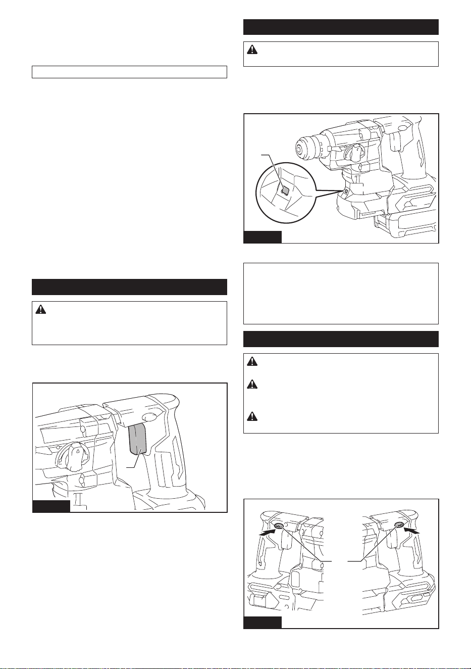
Switch action
WARNING: Before installing the battery car-
tridge into the tool, always check to see that the
switch trigger actuates properly and returns to
the "OFF" position when released.
To start the tool, simply pull the switch trigger. Tool
speed is increased by increasing pressure on the switch
trigger. Release the switch trigger to stop.
1
Fig.3
►1. Switch trigger
Lighting up the front lamp
CAUTION: Do not look in the light or see the
source of light directly.
Pull the switch trigger to light up the lamp. The lamp
keeps on lighting while the switch trigger is being pulled.
The lamp goes out approximately 10 seconds after
releasing the switch trigger.
1
Fig.4
►1. Lamp
NOTE:Useadryclothtowipethedirtothelensof
the lamp. Be careful not to scratch the lens of lamp, or
it may lower the illumination.
NOTE: The front lamp cannot be used while the dust
collection system (optional accessory) is installed in
the tool.
Reversing switch action
CAUTION: Always check the direction of
rotation before operation.
CAUTION:
Use the reversing switch only after
the tool comes to a complete stop. Changing the direc-
tion of rotation before the tool stops may damage the tool.
CAUTION:
When not operating the tool, always
set the reversing switch lever to the neutral position.
This tool has a reversing switch to change the direction
of rotation. Depress the reversing switch lever from the
A side for clockwise rotation or from the B side for coun-
terclockwise rotation.
When the reversing switch lever is in the neutral posi-
tion, the switch trigger cannot be pulled.
1
AB
Fig.5
►1. Reversing switch lever
9 ENGLISH
Selecting the action mode
NOTICE: Do not rotate the action mode chang-
ing knob when the tool is running. The tool will be
damaged.
NOTICE: To avoid rapid wear on the mode
change mechanism, be sure that the action mode
changing knob is always positively located in one
of the three action mode positions.
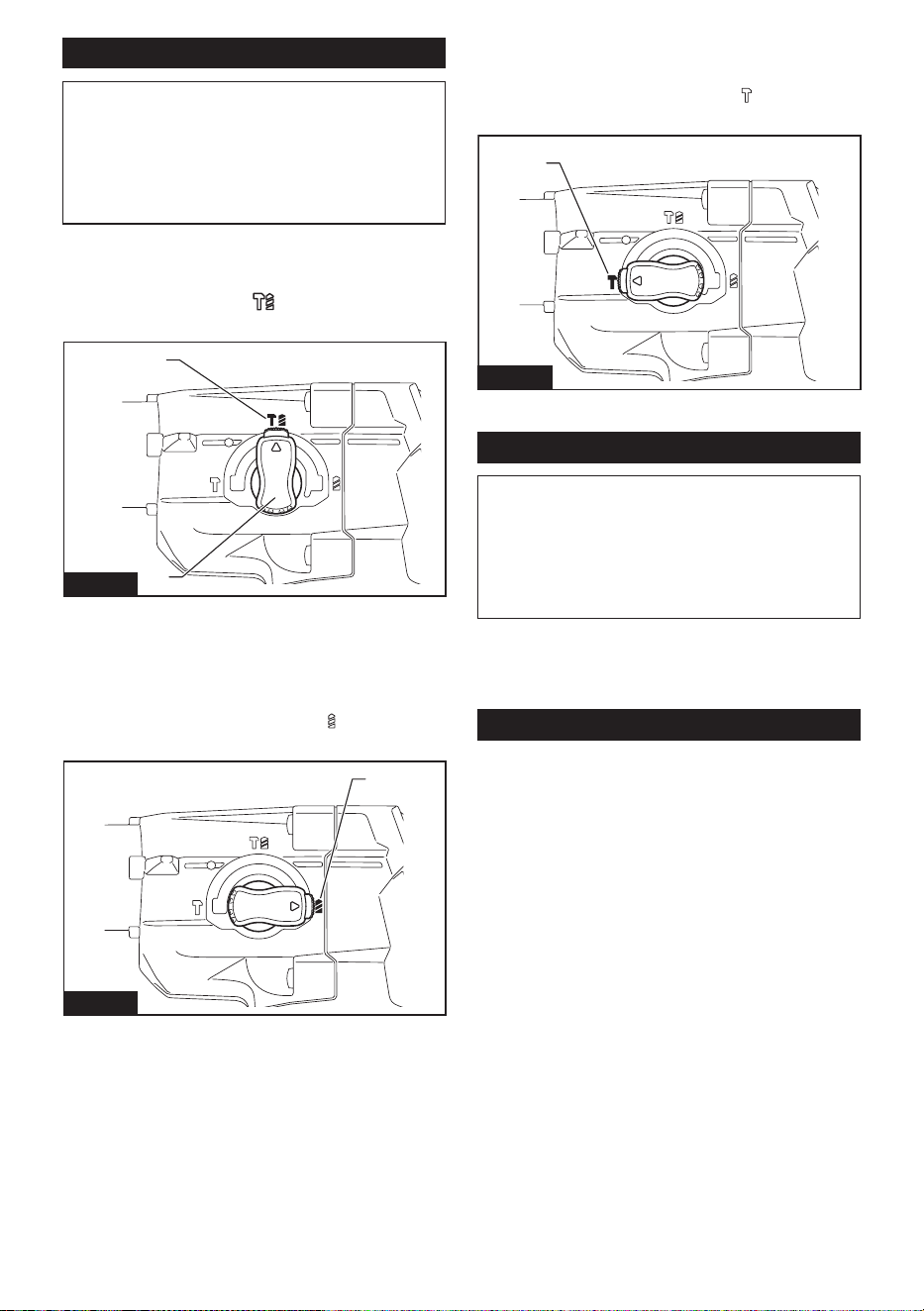
Rotation with hammering
For drilling in concrete, masonry, etc., rotate the action
mode changing knob to the symbol. Use a tungsten
carbide tipped bit.
1
2
Fig.6
►1. Rotation with hammering 2. Action mode chang-
ing knob
Rotation only
For drilling in wood, metal or plastic materials, rotate
the action mode changing knob to the symbol. Use a
twist drill bit or wood drill bit.
1
Fig.7
►1. Rotation only
Hammering only
For chipping, scaling or demolition operations, rotate
the action mode changing knob to the symbol. Use a
bull point, cold chisel, scaling chisel, etc.
1
Fig.8
►1. Hammering only
Torque limiter
NOTICE: As soon as the torque limiter actuates,
switch o the tool immediately. This will help pre-
vent premature wear of the tool.
NOTICE: Drill bits such as hole saw, which tend
to pinch or catch easily in the hole, are not appro-
priate for this tool. This is because they will cause
the torque limiter to actuate too frequently.
The torque limiter will actuate when a certain torque
level is reached. The motor will disengage from the
output shaft. When this happens, the drill bit will stop
turning.
Electronic function
The tool is equipped with the electronic functions for
easy operation.
• Electric brake
This tool is equipped with an electric brake. If the
tool consistently fails to quickly cease to function
after the switch trigger is released, have the tool
serviced at a Makita service center.
• Constant speed control
The speed control function provides the constant
rotation speed regardless of load conditions.
10 ENGLISH
ASSEMBLY
CAUTION: Always be sure that the tool is
switched o and the battery cartridge is removed
before carrying out any work on the tool.
Side grip (auxiliary handle)
CAUTION: Always use the side grip to ensure
safe operation.
CAUTION: After installing or adjusting the
side grip, make sure that the side grip is rmly
secured with the protrusions on the tool are fully
engaged by the grooves on the side grip.
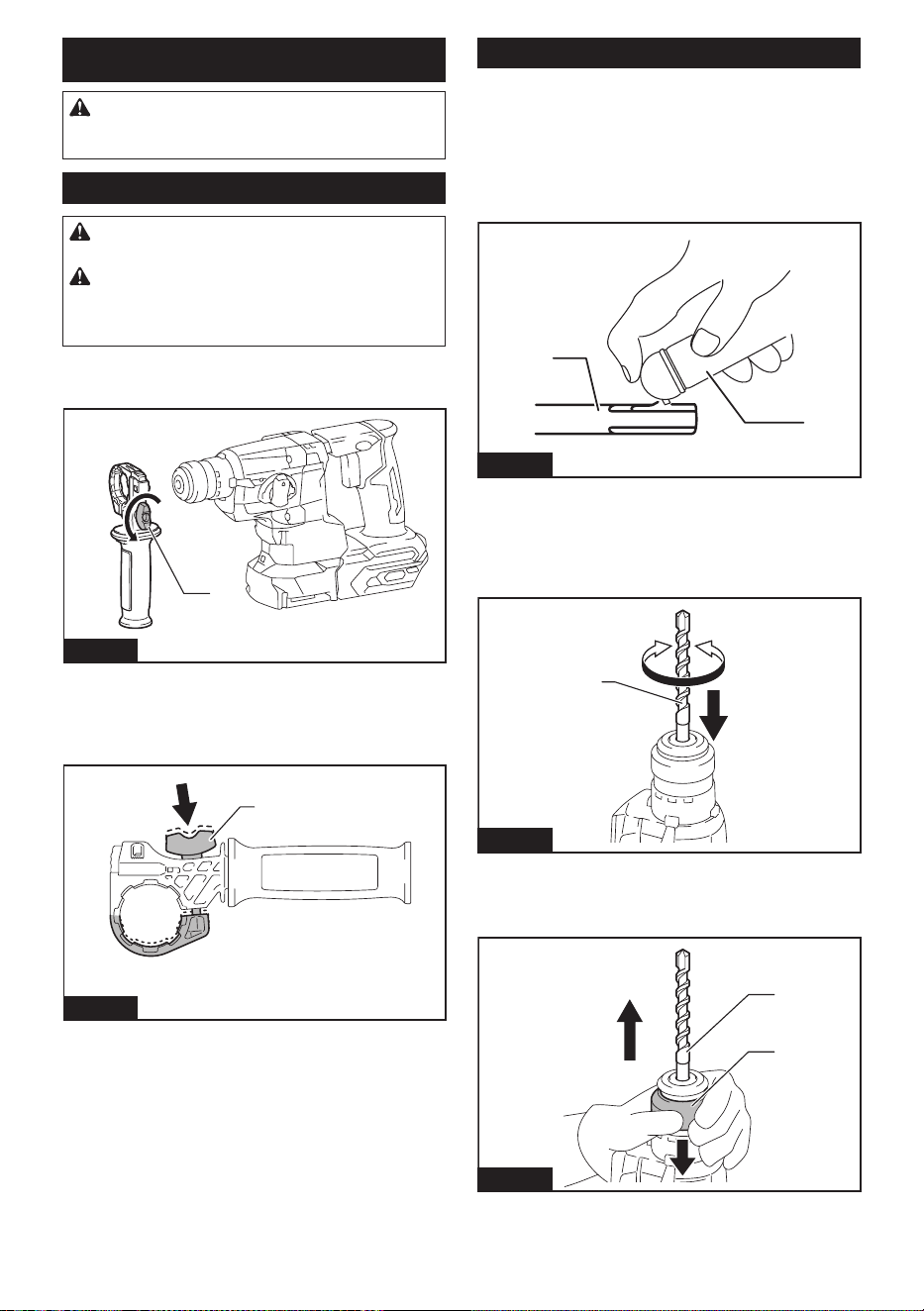
To install the side grip, follow the steps below.
1. Loosen the thumb screw on the side grip.
1
Fig.9
►1. Thumb screw
2. Install the side grip so that the grooves on the
griptintheprotrusionsonthetoolwhilepressingthe
thumb screw.
1
Fig.10
►1. Thumb screw
3. Tighten the thumb screw to secure the grip. The
gripcanbexedatdesiredangle.
To remove the side grip, loosen the thumb screw on the
side grip. Remove the side grip from the tool.
Installing or removing drill bit
Grease
Clean the shank end of the bit and apply grease before
installing the bit.
Coat the shank end of the bit beforehand with a small
amount of grease (about 0.5 - 1 g). This chuck lubrica-
tion assures smooth action and longer service life.
1
2
Fig.11
►1. Shank end 2. Grease
Insert the drill bit into the tool. Turn the drill bit and push
it in until it engages.
After installing the drill bit, always make sure that the
drill bit is securely held in place by trying to pull it out.
1
Fig.12
►1. Drill bit
To remove the drill bit, push the chuck cover down all
the way and pull the drill bit out.
1
2
1
2
Fig.13
►1. Drill bit 2. Chuck cover
11 ENGLISH
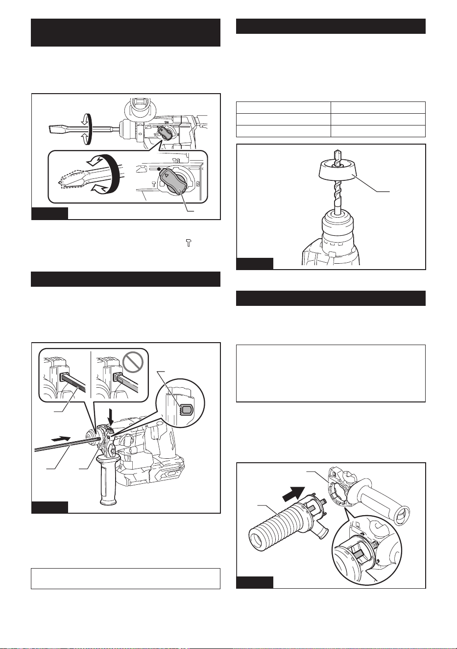
Chisel angle (when chipping,
scaling or demolishing)
The chisel can be secured at the desired angle. To
change the chisel angle, rotate the action mode chang-
ing knob to the O symbol. Turn the chisel to the desired
angle.
1
Fig.14
►1. Action mode changing knob
Rotate the action mode changing knob to the
sym-
bol. Then make sure that the chisel is securely held in
place by turning it slightly.
Depth gauge
The depth gauge is convenient for drilling holes of
uniform depth.
Press and hold the lock button, and then insert the
depth gauge into the hole. Make sure that the toothed
side of the depth gauge faces the marking.
3
1 2
4
Fig.15
►1. Depth gauge 2. Lock button 3. Marking
4. Toothed side
Adjustthedepthgaugebymovingitbackandforth
whilepressingthelockbutton.Aftertheadjustment,
release the lock button to lock the depth gauge.
NOTE: Make sure that the depth gauge does not
touch the main body of the tool when attaching it.
Dust cup
Optional accessory
Use the dust cup to prevent dust from falling over the
tool and on yourself when performing overhead drilling
operations. Attach the dust cup to the bit as shown in
thegure.Thesizeofbitswhichthedustcupcanbe
attached to is as follows.
Model Bit diameter
Dust cup 5 6 mm (1/4") - 14.5 mm (9/16")
Dust cup 9 12 mm (15/32") - 16 mm (5/8")
1
Fig.16
►1. Dust cup
Dust cup set
Optional accessory
Installing the dust cup set
NOTICE: Do not use the dust cup set when drill-
ing in metal or similar. It may damage the dust cup
set due to the heat produced by small metal dust or
similar. Do not install or remove the dust cup set with
the drill bit installed in the tool. It may damage the
dust cup set and cause dust leak.
Before installing the dust cup set, remove the drill bit
from the tool if installed.
1. Loosen the thumb screw on the side grip.
2. Install the dust cup set so that the claws of the
dustcuptintheslitsonthesidegrip.
2
1
Fig.17
►1. Dust cup set 2. Side grip
12 ENGLISH
3. Install the side grip so that the groove on the grip
tintheprotrusiononthetool.Tightenthethumbscrew
to secure the side grip.
1
2
3
Fig.18
►1. Side grip 2. Groove 3. Protrusion
NOTE: If you connect a vacuum cleaner to the dust
cup set, remove the dust cap before connecting the
vacuum cleaner.
1
Fig.19
►1. Dust cap
Removing the drill bit
To remove the drill bit, pull the chuck cover down all the
way and pull the drill bit out.
1
2
Fig.20
►1. Drill bit 2. Chuck cover
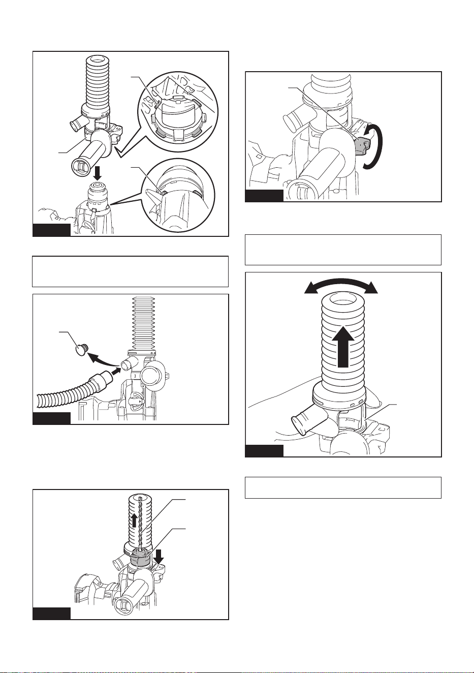
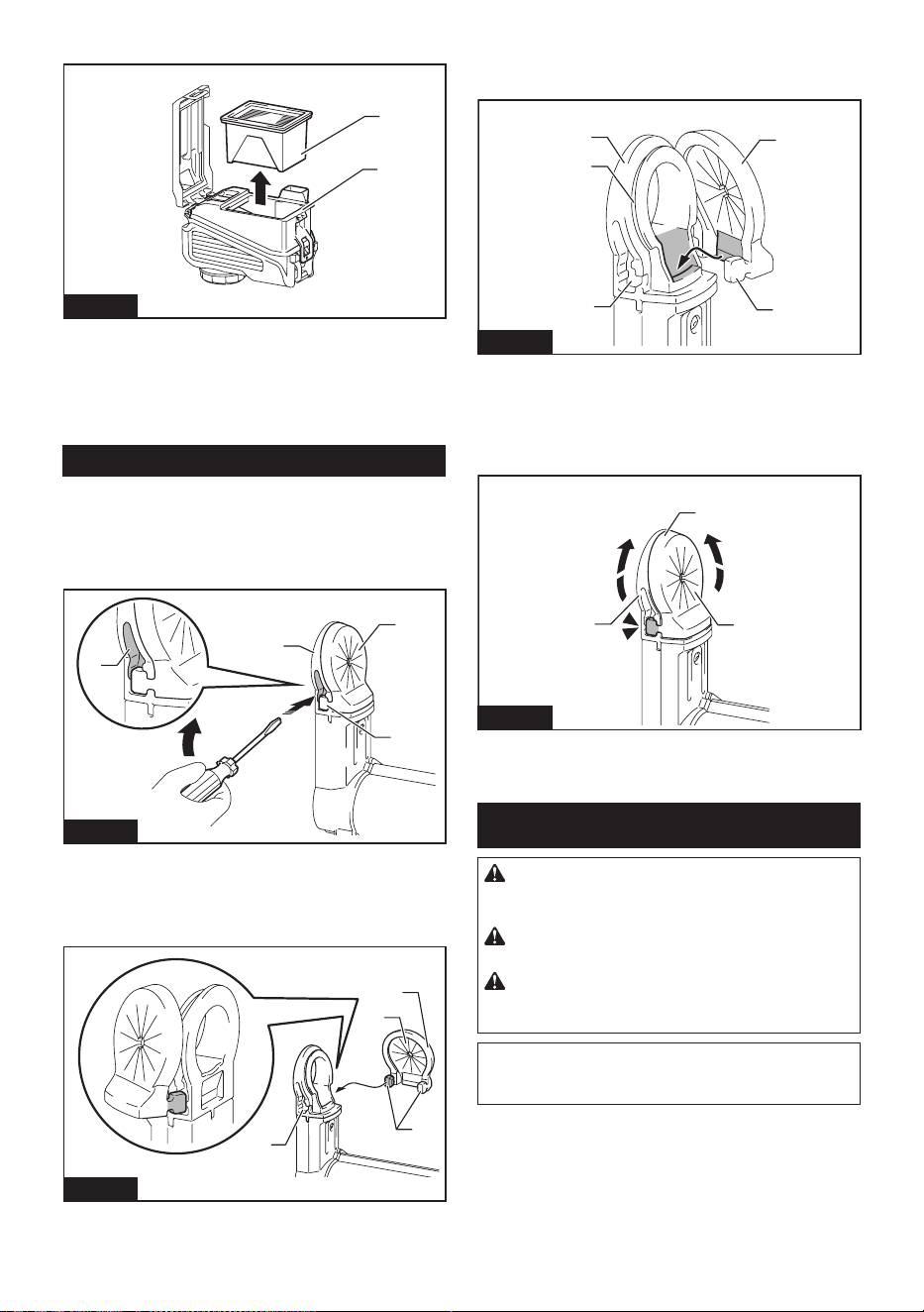
Removing the dust cup set
To remove the dust cup set, follow the steps below.
1. Loosen the thumb screw on the side grip. Remove
the side grip from the tool.
1
Fig.21
►1. Thumb screw
2. Hold the root of dust cup and pull it out.
NOTE:Ifitisdiculttoremovethedustcupset,
remove the claws of the dust cup one by one by
swinging and pulling the root of the dust cup.
1
Fig.22
►1. Dust cup
NOTE:Ifthecapcomesofromthedustcupset,
place it back to the original position.
13 ENGLISH
To place the cap back to the original position, follow the
steps below.
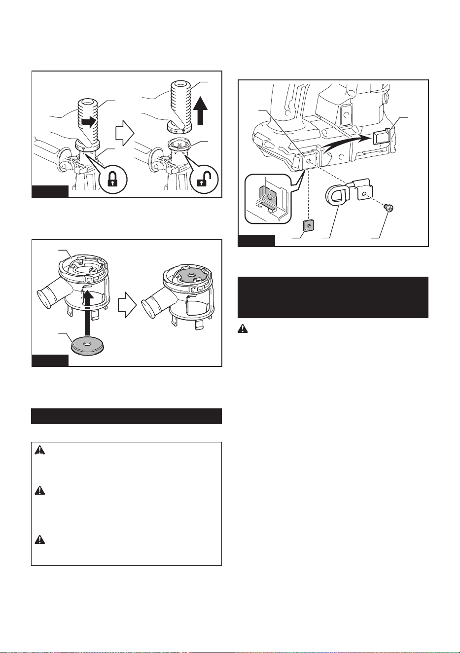
1. Turn the bellows counterclockwise and remove it
from the dust cup set attachment unit while the bellows
is unlocked.
1
2
1
2
Fig.23
►1. Bellows 2. Attachment unit
2. Set the cap back in place with its lettered side
facing upwards.
1
2
Fig.24
►1. Cap 2. Attachment unit
3. Besurethatthegroovesaroundthecapwelltin
the lips of the upper opening of the attachment unit.
Tool hanger
Optional accessory
CAUTION: Do not use damaged tool hanger
and screw. Before use, always check for dam-
ages, cracks or deformations, and make sure that
the screw is tightened.
CAUTION: Install or remove the tool hanger
on a stable table or surface. Be sure to use the
screw provided with the tool hanger only. After
installing the tool hanger, make sure that the tool
hanger is securely installed with the screw.
CAUTION: Do not remove the battery car-
tridge while hanging the tool. The tool may fall if the
screw is not tightened.
The tool hanger is intended for connecting the lanyard
(tether strap).
Before installing the tool hanger, remove the rubber cap
from the screw hole in the mounting bracket. Insert the
square nut under the bracket. Tighten the tool hanger
with screw in place.
1
2
3
5
4
Fig.25
►1. Rubber cap 2. Mounting bracket 3. Square nut
4. Tool hanger 5. Screw
Safety warnings about connecting
lanyard (tether strap) to the tool
hanger
Safety warnings specic for use at height
Read all safety warnings and instructions. Failure
to follow the warnings and instructions may result in
seriousinjury.
1. Always keep the tool tethered when working
"at height". Maximum lanyard length is 2 m
(6.5 ft).
The maximum permissible fall height for lan-
yard (tether strap) must not exceed 2 m (6.5 ft).
2. Do not anchor the tool lanyard to anything on
your body or on movable components. Anchor
the tool lanyard to a rigid structure that can
withstand the forces of a dropped tool.
3. Make sure the lanyard is properly secured at
each end prior to use.
4. Inspect the tool and lanyard before each use
for damage and proper function (including
fabric and stitching). Do not use if damaged or
not functioning properly.
5. Do not wrap lanyards around or allow them to
come in contact with sharp or rough edges.
6. Fasten the other end of the lanyard outside
the working area so that a falling tool is held
securely.
7. Attach the lanyard so that the tool will move
away from the operator if it falls. Dropped tools
willswingonthelanyard,whichcouldcauseinjury
or loss of balance.
8. Do not use near moving parts or running
machinery. Failure to do so may result in a crush
or entanglement hazard.
14 ENGLISH
9. Do not carry the tool by the attachment device
or the lanyard.
10. Only transfer the tool between your hands
while you are properly balanced.
11. Do not attach lanyards to the tool in a way that
keeps switches or trigger-lock (if supplied)
from operating properly.
12. Avoid getting tangled in the lanyard.
13. Keep lanyard away from the drilling area of the
tool.
14. Use a locking carabiner (multi-action and
screw gate type). Do not use single action
spring clip carabiners.
15. In the event the tool is dropped, it must be
tagged and removed from service, and should
be inspected by a Makita Factory or Authorized
Service Center.
16. Do not hang the tool on your waist. Heated tool
and its accessory may touch your skin and burn
injuryresult.
2
1
Fig.26
►1. Tool hanger 2. Lanyard (tether strap)
DUST COLLECTION
SYSTEM
Optional accessory
The dust collection system is designed to collect dusts
eectivelywhentheconcretedrillingoperation.
1
Fig.27
►1. Dust collection system
CAUTION: The dust collection system is
intended for drilling in concrete only. Do not use
the dust collection system for drilling in metal or
wood.
CAUTION: When using the tool with the dust
collection system, be sure to attach the lter
to the dust collection system to prevent dust
inhalation.
CAUTION: Before using the dust collection
system, check that the lter is not damaged and
the inner pipe is free of dust and foreign matter.
Failure to do so may cause dust inhalation.
CAUTION: The dust collection system col-
lects the generated dust at a considerable rate,
but not all dust can be collected.
NOTICE: Do not use the dust collection system
for core drilling or chiseling.
NOTICE: Do not use the dust collection system
for metal or wood. The dust collection system is
intended for concrete only.
NOTICE: Do not use the dust collection system
for drilling in wet concrete or use this system
in wet environment. Failure to do so may cause
malfunction.
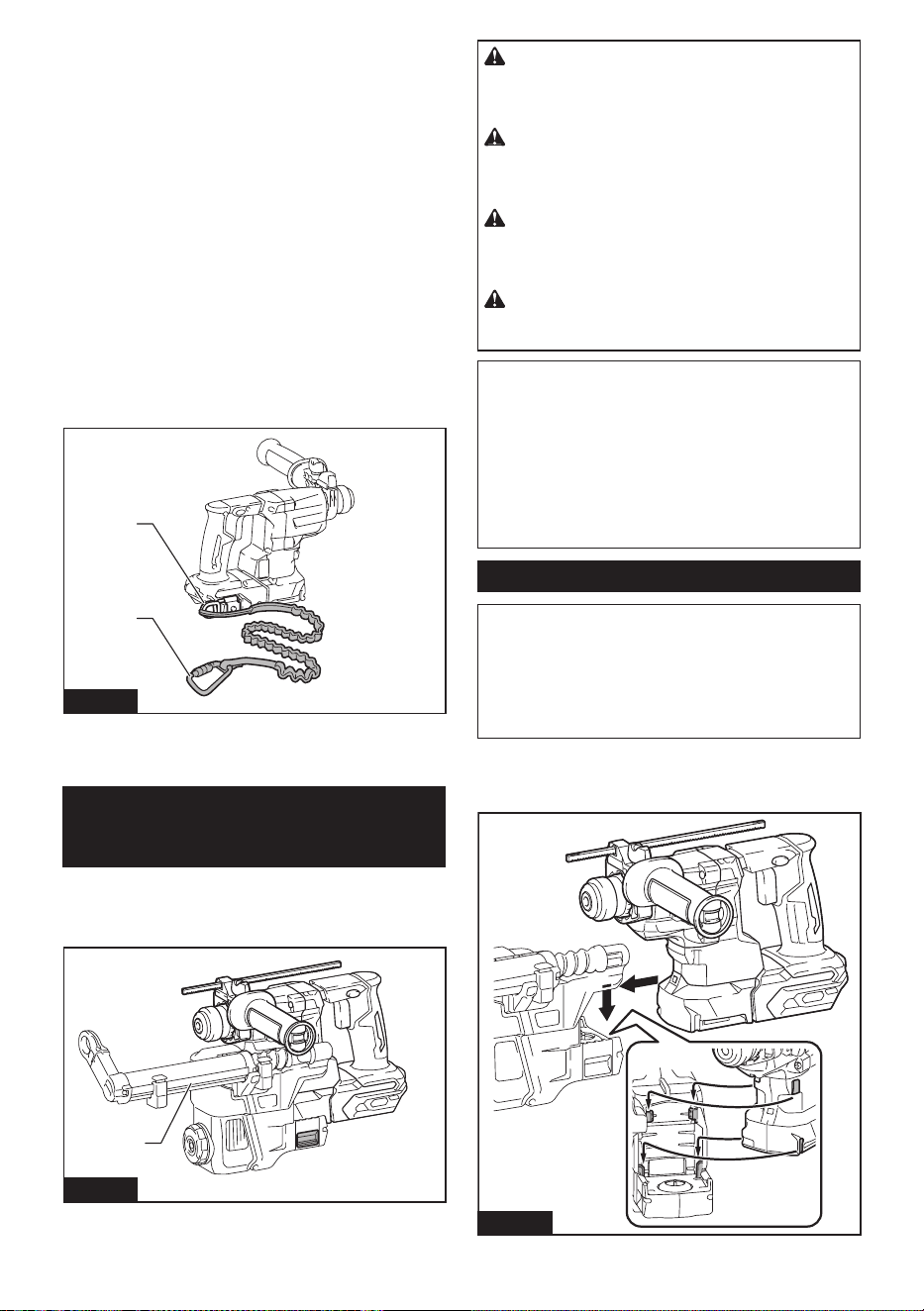
Installing or removing
NOTICE: Before installing the dust collection
system, clean the joint parts of the tool and the
dust collection system. Foreignmattersonthejoint
partsmaycauseitdiculttoinstallthedustcollection
system. If any dust remains on the air duct, the dust
comesintothetoolandcausesjamintheairowor
breakage of the tool.
To install the dust collection system, insert the tool
completely into the dust collection system until the tool
is locked in place with a little click.
Fig.28
15 ENGLISH
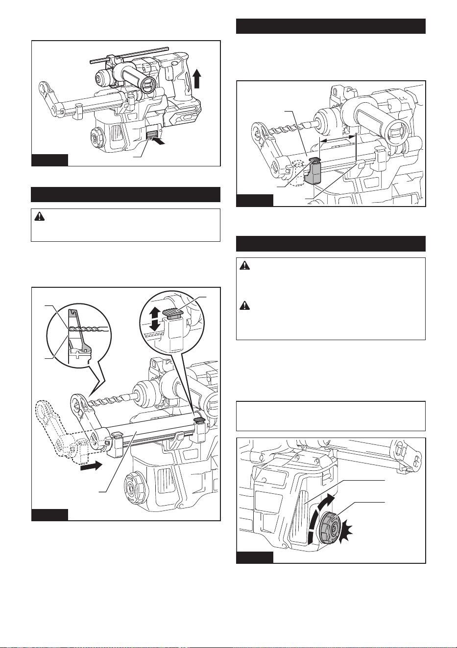
To remove the dust collection system, pull up the tool
whilepressingthelock-obutton.
1
Fig.29
►1.Lock-obutton
Adjusting nozzle position
CAUTION: Do not point the nozzle at yourself
or others when releasing the nozzle by pushing
the guide adjustment button.
Slide in and out the nozzle guide while pressing the
guideadjustmentbutton,andthenreleasethebutton
atanexactpositionwherethetipofthedrillbitsitsjust
behind the front surface of the nozzle.
1
2
3
4
Fig.30
►1. Nozzle guide 2.Guideadjustmentbutton3. Tip of
drill bit 4. Front surface of nozzle
Adjusting drilling depths
Drillingdepthscanbeadjustedbychangingthelengths
betweenthedepthadjustmentbuttonandthesupport
armfornozzleguide.Pressandholdthedepthadjust-
ment button and slide it to your desired position.
4
3
1
2
Fig.31
►1.Depthadjustmentbutton2. Nozzle guide
3. Support arm for nozzle guide 4. Drilling depths
Beating dust on the lter
CAUTION: Do not turn the dial on the dust
case while the dust case is removed from the
dust collection system. Doing so may cause dust
inhalation.
CAUTION: Always switch o the tool when
turning the dial on the dust case. Turning the dial
while the tool is running may result in the loss of
control of the tool.
Bybeatingthedustonthelterinsidethedustcase,
youcankeepthevacuumeciencyandalsoreduce
the number of times to dispose of the dust.
Turn the dial on the dust case three times after col-
lecting every 50,000 mm
3
of dust or when you feel the
vacuum performance declined.
NOTE: 50,000 mm
3
of dust equivalents to drilling 10
holesofø10mmand65mmdepth(14holesofø3/8″
and2″depth).
1
2
Fig.32
►1. Dust case 2. Dial
16 ENGLISH
Disposing of dust
CAUTION: Always be sure that the tool is
switched o and the battery cartridge is removed
before carrying out any work on the tool.
CAUTION: Be sure to wear dust mask when
disposing of dust.
CAUTION: Be sure that the tool is completely
stopped when disposing of dust.
CAUTION: Empty the dust case regularly
before the dust case becomes full. Failure to do so
may decrease the dust collection performance and
cause dust inhalation.
CAUTION: The performance of dust collection
decreases if the lter in the dust case become
clogged. Replace the lter with new one after
approximately 200 times of dust fulllment as a
guide. Failure to do so may cause dust inhalation.
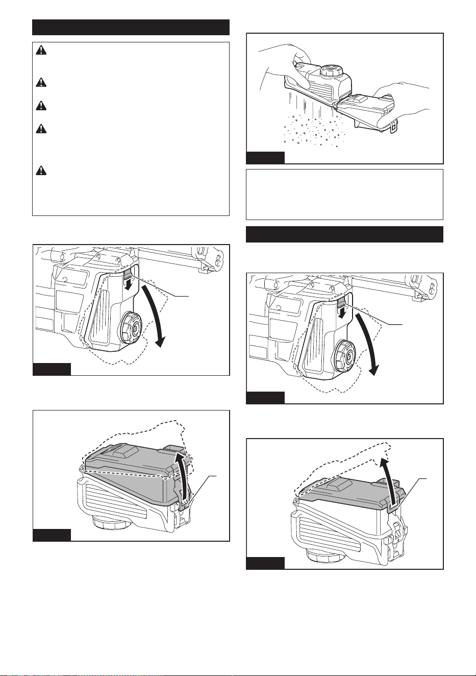
1. Remove the dust case while pressing down the
lever of the dust case.
1
Fig.33
►1. Lever
2. Open the cover of the dust case.
1
Fig.34
►1. Cover
3. Disposeofthedust,andthencleanthelter.
Fig.35
NOTICE: When cleaning the lter, tap the case
of the lter gently by hand to remove dust. Do not
tap the lter directly; touch the lter with brush
or similar; or blow compressed air on the lter.
Doing so may damage the lter.
Replacing lter of dust case
1. Remove the dust case while pressing down the
lever of the dust case.
1
Fig.36
►1. Lever
2. Opentheltercoverofthedustcase.
1
Fig.37
►1. Filter cover
17 ENGLISH
3. Removethelterfromtheltercase.
1
2
Fig.38
►1. Filter 2. Filter case
4. Attachanewltertotheltercase,andthen
attachtheltercover.
5. Close the cover of the dust case, and then attach
the dust case to the dust collection system.
Replacing sealing cap
1.
Insertaat-bladescrewdriverintooneofthegrooves
placedonthesidesofthenozzlehead.Tilttheat-blade
screwdriver at an angle to squeeze and pop the cube hook
of the sealing cap out. Then peel the rubber edge of the
sealing cap away from the rim of the nozzle head opening.
1
2
3
4
Fig.39
►
1. Sealing cap 2. Cube hook 3. Groove 4. Nozzle head
2. Set one of cube hooks of a new sealing cap into
the lower part of the groove in the nozzle head with a
recessed surface of the sealing cap facing forward.
1
2
4
3
Fig.40
►1. Cube hooks 2. Lower part of the groove
3. Sealing cap 4. Recessed surface
3. Place the other hook into the opposite side, while
repositioningthesealingcaptotnelytothenozzle
head.
2
1
3
4
5
Fig.41
►1. Sealing cap 2. Cube hook 3. Lower part of the
groove 4. Nozzle head 5. Rims
4. Gently lay the rubber edge of the sealing cap
down over the rim of the nozzle head opening from
bottom to top.
1
2
3
Fig.42
►1. Rubber edge 2. Sealing cap 3. Nozzle head
OPERATION
CAUTION: Always use the side grip (auxiliary
handle) and rmly hold the tool by both side grip
and switch handle during operations.
CAUTION: Always make sure that the work-
piece is secured before operation.
CAUTION: Do not pull the tool out forcibly
even the bit gets stuck. Loss of control may
cause injury.
NOTICE: Before using the dust collection sys-
tem with the tool, read the section about the dust
collection system.
18 ENGLISH
NOTE: If the battery cartridge is in low temperature,
the tool’s capability may not be fully obtained. In this
case, warm up the battery cartridge by using the
tool with no load for a while to fully obtain the tool’s
capability.
Fig.43
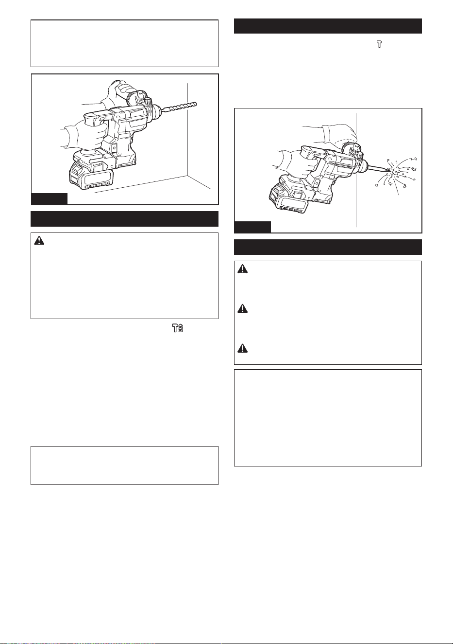
Hammer drilling operation
CAUTION: There is tremendous and sudden
twisting force exerted on the tool/drill bit at the time of
hole break-through, when the hole becomes clogged
with chips and particles, or when striking reinforcing
rods embedded in the concrete. Always use the side
grip (auxiliary handle) and rmly hold the tool by
both side grip and switch handle during opera-
tions. Failure to do so may result in the loss of control
ofthetoolandpotentiallysevereinjury.
Set the action mode changing knob to the symbol.
Position the drill bit at the desired location for the hole,
then pull the switch trigger.
Apply feed force to the switch handle (main handle) for
workingaccuracyandeciency,andholdthesidegrip
(auxiliary handle) to keep balance of the tool.
Keep the tool in position and prevent it from slipping
away from the hole.
Do not apply more pressure when the hole becomes
clogged with chips or particles. Instead, run the tool at
an idle, then remove the drill bit partially from the hole.
By repeating this several times, the hole will be cleaned
out and normal drilling may be resumed.
NOTE: Eccentricity in the drill bit rotation may occur
while operating the tool with no load. The tool auto-
matically centers itself during operation. This does not
aectthedrillingprecision.
Chipping/Scaling/Demolition
Set the action mode changing knob to the symbol.
Holdthetoolrmlywithbothhands.Turnthetoolon.
Apply feed force to the switch handle (main handle) for
workingaccuracyandeciency,andholdthesidegrip
(auxiliary handle) to keep balance of the tool.
Pressing very hard on the tool will not increase the
eciency.
Fig.44
Drilling in wood or metal
CAUTION: Hold the tool rmly and exert care
when the drill bit begins to break through the
workpiece. There is a tremendous force exerted on
the tool/drill bit at the time of hole break through.
CAUTION: A stuck drill bit can be removed
simply by setting the reversing switch to reverse
rotation in order to back out. However, the tool
may back out abruptly if you do not hold it rmly.
CAUTION: Always secure workpieces in a
vise or similar hold-down device.
NOTICE: Never use “rotation with hammering”
when the drill chuck is installed on the tool. The
drill chuck may be damaged.
Also,thedrillchuckwillcomeowhenreversingthe
tool.
NOTICE: Pressing excessively on the tool will
not speed up the drilling. In fact, this excessive
pressure will only serve to damage the tip of your drill
bit, decrease the tool performance and shorten the
service life of the tool.
19 ENGLISH
Set the action mode changing knob to the
symbol.
Attach the chuck adapter to a keyless drill chuck to
which 1/2"-20 size screw can be installed, and then
install them to the tool. When installing it, refer to the
section “Installing or removing drill bit”.
1
2
Fig.45
►1. Drill chuck assembly 2. Chuck adapter
Diamond core drilling
NOTICE: If performing diamond core drilling
operations using “rotation with hammering”
action, the diamond core bit may be damaged.
When performing diamond core drilling opera-
tions, always set the action mode changing knob to
the position to use "rotation only" action.
Blow-out bulb
Optional accessory
After drilling the hole, use the blow-out bulb to clean the
dust out of the hole.
Fig.46
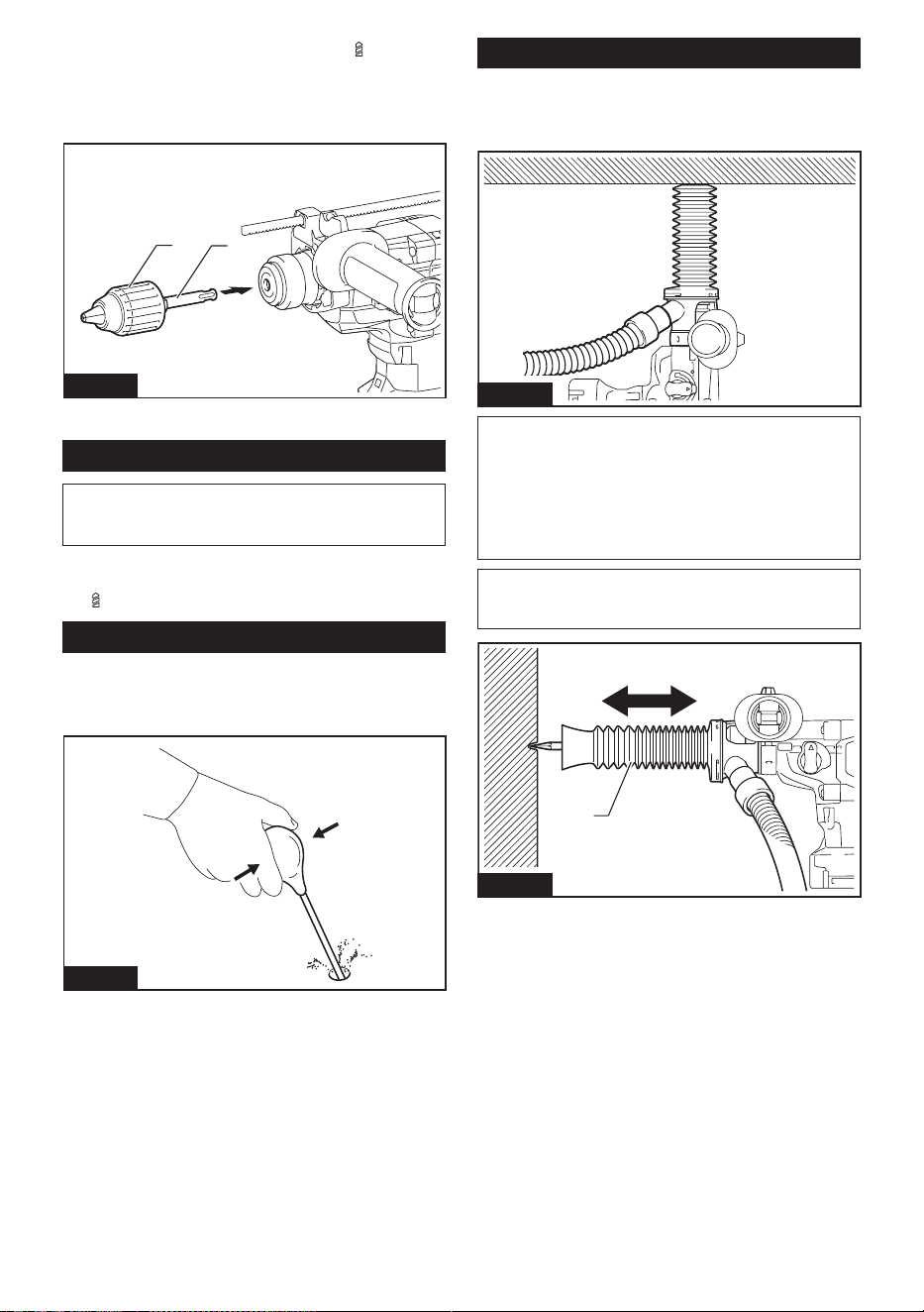
Using dust cup set
Optional accessory
Fit the dust cup set against the ceiling when operating
the tool.
Fig.47
NOTICE: Do not use the dust cup set when drill-
ing in metal or similar. It may damage the dust
cup set due to the heat produced by small metal
dust or similar.
NOTICE: Do not install or remove the dust cup
set with the drill bit installed in the tool. It may
damage the dust cup set and cause dust leak.
NOTE:Whenusingthebellowsforchiselling,adjust
the length by expanding and contracting the bellows
according to the length of the bit.
1
Fig.48
►1. Bellows for chiselling
20 ENGLISH
WIRELESS ACTIVATION
FUNCTION
Optional accessory
What you can do with the wireless
activation function
The wireless activation function enables clean and com-
fortable operation. By connecting a supported vacuum
cleaner to the tool, you can run the vacuum cleaner
automatically along with the switch operation of the tool.
Fig.49
To use the wireless activation function, prepare follow-
ing items:
• A wireless unit (optional accessory)
• A vacuum cleaner which supports the wireless
activation function
The overview of the wireless activation function
setting is as follows. Refer to each section for detail
procedures.
1. Installing the wireless unit
2. Tool registration for the vacuum cleaner
3. Starting the wireless activation function
Installing the wireless unit
Optional accessory
CAUTION: Place the tool on a at and stable
surface when installing the wireless unit.
NOTICE: Clean the dust and dirt on the tool
before installing the wireless unit. Dust or dirt
may cause malfunction if it comes into the slot of the
wireless unit.
NOTICE: To prevent the malfunction caused by
static, touch a static discharging material, such
as a metal part of the tool, before picking up the
wireless unit.
NOTICE: When installing the wireless unit,
always be sure that the wireless unit is inserted
in the correct direction and the lid is completely
closed.
1. Openthelidonthetoolasshowninthegure.
1
Fig.50
►1. Lid
2. Insert the wireless unit to the slot and then close
the lid.
Wheninsertingthewirelessunit,aligntheprojections
with the recessed portions on the slot.
1
2
3
4
Fig.51
►1. Wireless unit 2.Projection3. Lid 4. Recessed
portion
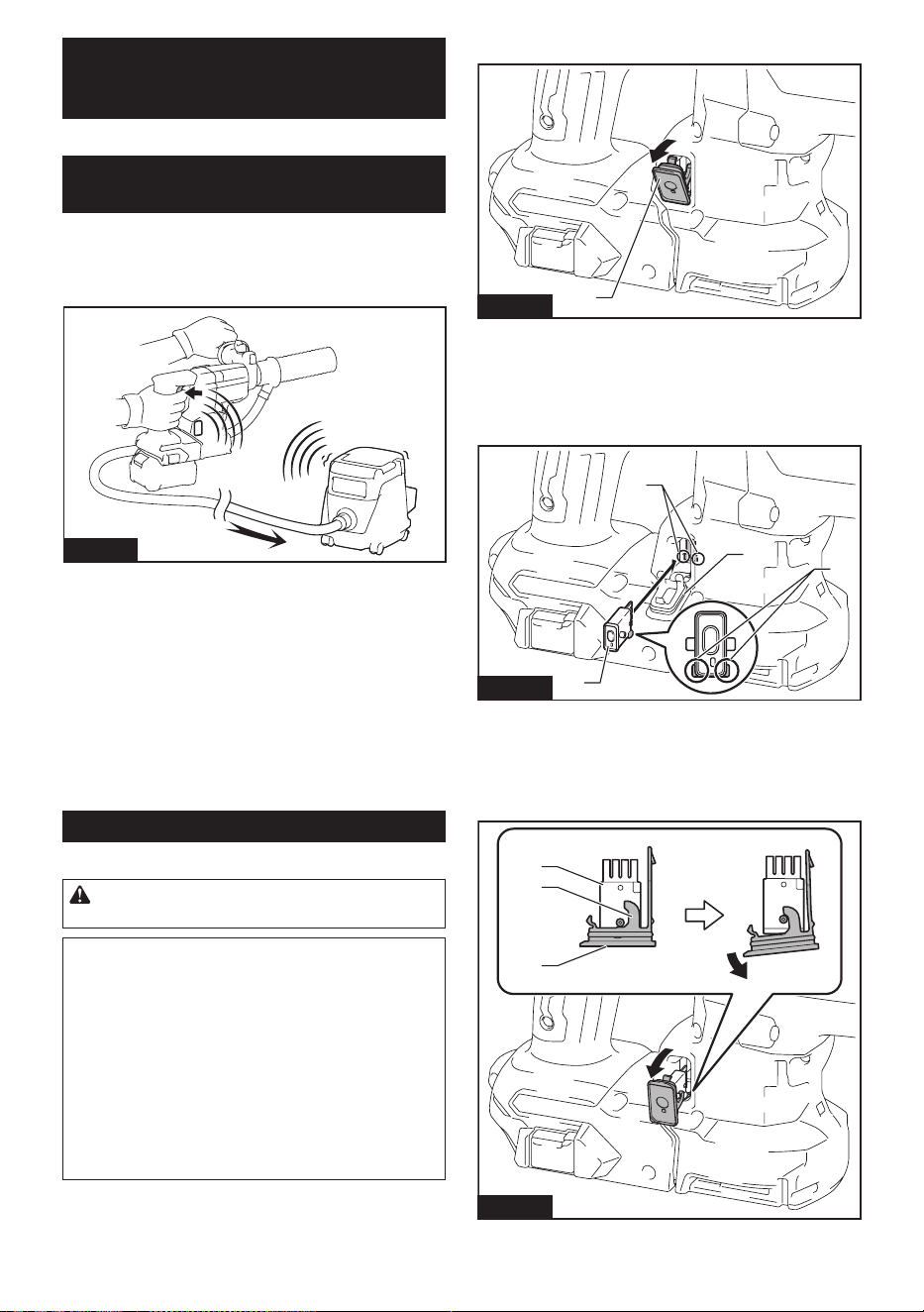
When removing the wireless unit, open the lid slowly.
The hooks on the back of the lid will lift the wireless unit
as you pull up the lid.
1
2
3
Fig.52
►1. Wireless unit 2. Hook 3. Lid
21 ENGLISH
After removing the wireless unit, keep it in the supplied
case or a static-free container.
NOTICE: Always use the hooks on the back of
the lid when removing the wireless unit. If the
hooks do not catch the wireless unit, close the lid
completely and open it slowly again.
Tool registration for the vacuum
cleaner
NOTE: A Makita vacuum cleaner supporting the
wireless activation function is required for the tool
registration.
NOTE: Finish installing the wireless unit to the tool
before starting the tool registration.
NOTE: During the tool registration, do not pull the
switch trigger or turn on the power switch on the
vacuum cleaner.
NOTE: Refer to the instruction manual of the vacuum
cleaner, too.
If you wish to activate the vacuum cleaner along with
theswitchoperationofthetool,nishthetoolregistra-
tion beforehand.
1. Install the batteries to the vacuum cleaner and the
tool.
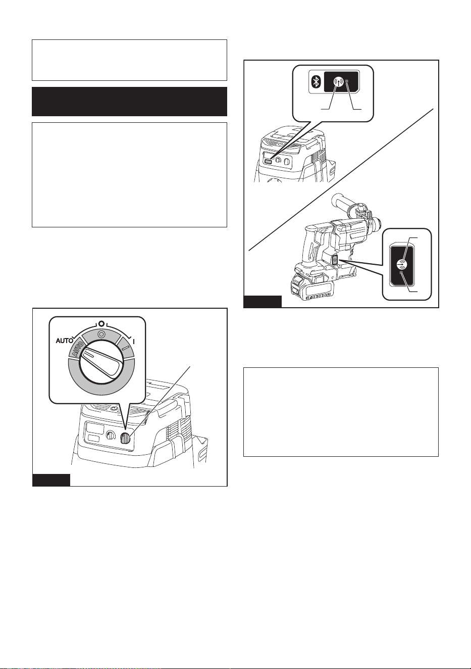
2. Set the stand-by switch on the vacuum cleaner to
"AUTO".
1
Fig.53
►1. Stand-by switch
3. Press the wireless activation button on the vac-
uum cleaner for 3 seconds until the wireless activation
lamp blinks in green. And then press the wireless acti-
vation button on the tool in the same way.
1
2
2
1
Fig.54
►1. Wireless activation button 2. Wireless activation
lamp
If the vacuum cleaner and the tool are linked success-
fully, the wireless activation lamps will light up in green
for 2 seconds and start blinking in blue.
NOTE:Thewirelessactivationlampsnishblinking
in green after 20 seconds elapsed. Press the wireless
activation button on the tool while the wireless acti-
vation lamp on the cleaner is blinking. If the wireless
activation lamp does not blink in green, push the wire-
lessactivationbuttonbrieyandholditdownagain.
NOTE: When performing two or more tool registra-
tionsforonevacuumcleaner,nishthetoolregistra-
tion one by one.
22 ENGLISH
Starting the wireless activation
function
NOTE: Finish the tool registration for the vacuum
cleaner prior to the wireless activation.
NOTE: Refer to the instruction manual of the vacuum
cleaner, too.
After registering a tool to the vacuum cleaner, the
vacuum cleaner will automatically runs along with the
switch operation of the tool.
1. Install the wireless unit to the tool.
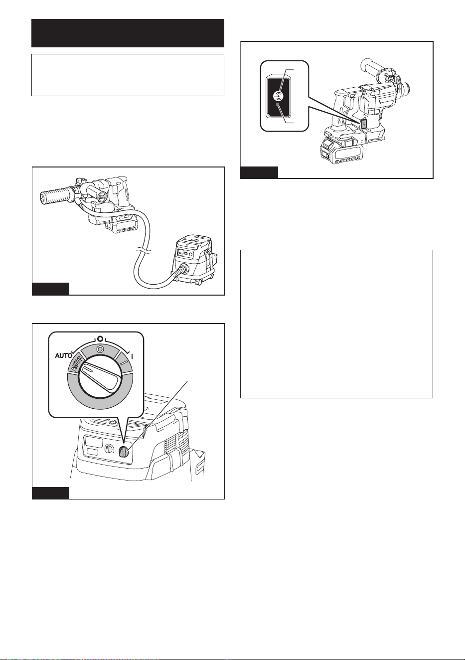
2. Connect the hose of the vacuum cleaner with the
tool.
Fig.55
3. Set the stand-by switch on the vacuum cleaner to
"AUTO".
1
Fig.56
►1. Stand-by switch
4. Push the wireless activation button on the tool
briey.Thewirelessactivationlampwillblinkinblue.
2
1
Fig.57
►1. Wireless activation button 2. Wireless activation
lamp
5. Turn on the tool. Check if the vacuum cleaner runs
while the tool is operating.
To stop the wireless activation of the vacuum cleaner,
push the wireless activation button on the tool.
NOTE: The wireless activation lamp on the tool will
stop blinking in blue when there is no operation for
2 hours. In this case, set the stand-by switch on the
vacuum cleaner to "AUTO" and push the wireless
activation button on the tool again.
NOTE: The vacuum cleaner starts/stops with a delay.
There is a time lag when the vacuum cleaner detects
a switch operation of the tool.
NOTE: The transmission distance of the wireless unit
may vary depending on the location and surrounding
circumstances.
NOTE: When two or more tools are registered to
one vacuum cleaner, the vacuum cleaner may start
running even if you do not turn on your tool because
another user is using the wireless activation function.
23 ENGLISH
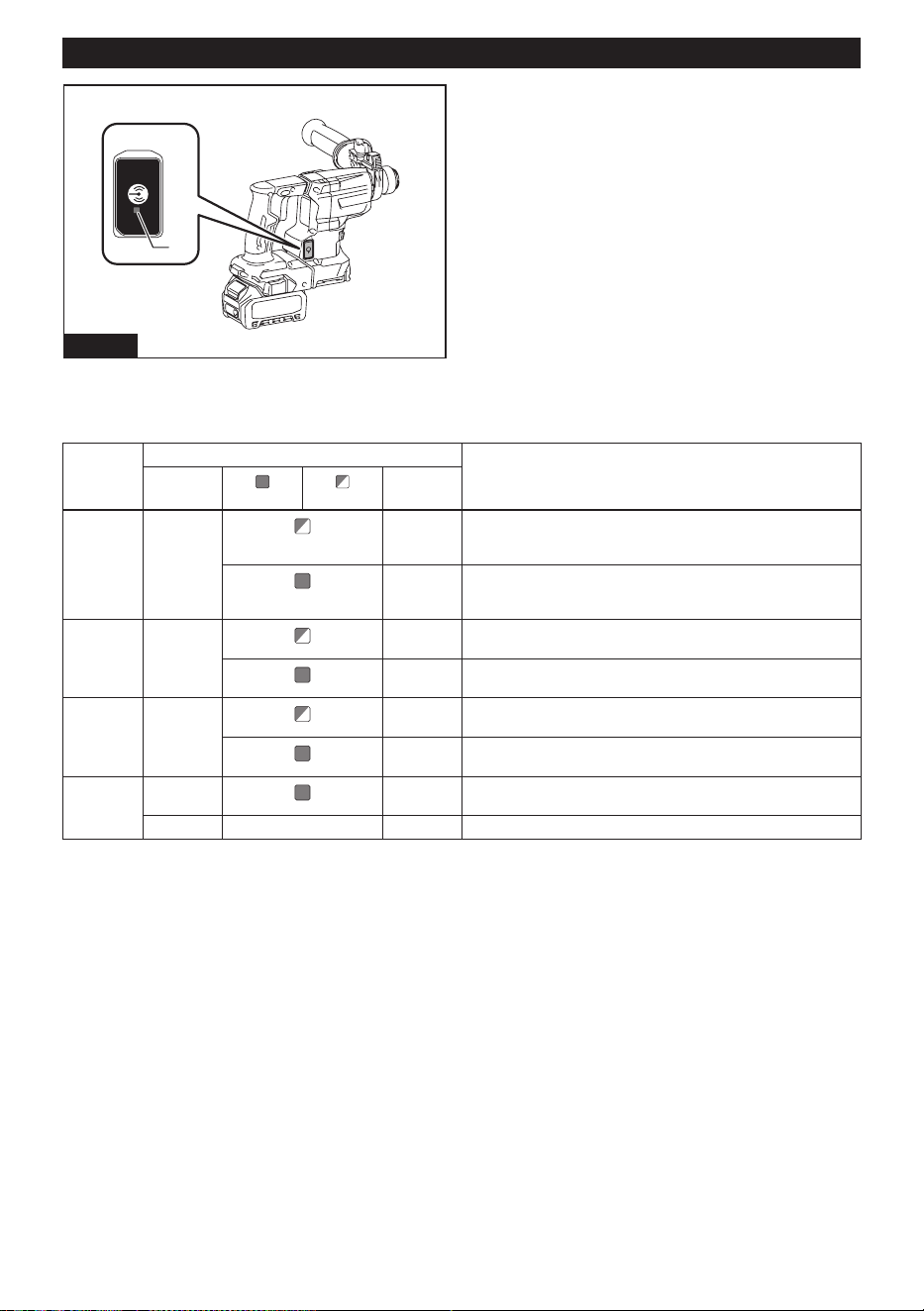
Description of the wireless activation lamp status
1
Fig.58
►1. Wireless activation lamp
The wireless activation lamp shows the status of the wireless activation function. Refer to the table below for the
meaning of the lamp status.
Status Wireless activation lamp Description
Color
On
Blinking
Duration
Standby Blue
2 hours The wireless activation of the vacuum cleaner is available. The
lampwillautomaticallyturnowhennooperationisperformed
for 2 hours.
When
the tool is
running.
The wireless activation of the vacuum cleaner is available and the
tool is running.
Tool
registration
Green
20 seconds Ready for the tool registration. Waiting for the registration by the
vacuum cleaner.
2 seconds Thetoolregistrationhasbeennished.Thewirelessactivation
lamp will start blinking in blue.
Cancelling
tool
registration
Red
20 seconds Ready for the cancellation of the tool registration. Waiting for the
cancellation by the vacuum cleaner.
2 seconds Thecancellationofthetoolregistrationhasbeennished.The
wireless activation lamp will start blinking in blue.
Others Red
3 seconds The power is supplied to the wireless unit and the wireless activa-
tion function is starting up.
O - - The wireless activation of the vacuum cleaner is stopped.
24 ENGLISH
Cancelling tool registration for the
vacuum cleaner
Perform the following procedure when cancelling the
tool registration for the vacuum cleaner.
1. Install the batteries to the vacuum cleaner and the
tool.
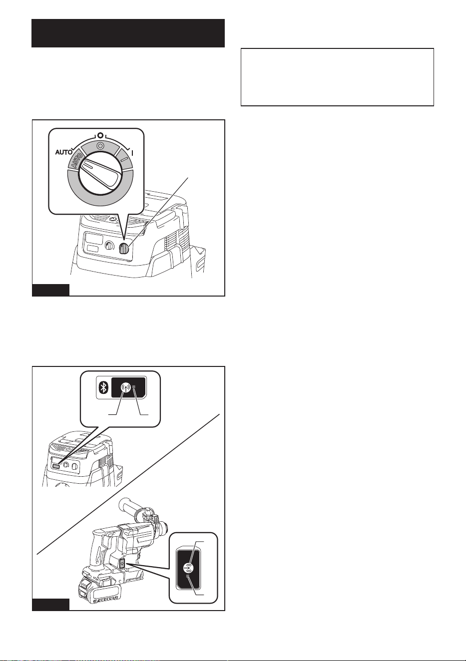
2. Set the stand-by switch on the vacuum cleaner to
"AUTO".
1
Fig.59
►1. Stand-by switch
3. Press the wireless activation button on the vac-
uum cleaner for 6 seconds. The wireless activation
lamp blinks in green and then become red. After that,
press the wireless activation button on the tool in the
same way.
1
2
2
1
Fig.60
►1. Wireless activation button 2. Wireless activation
lamp
If the cancellation is performed successfully, the wire-
less activation lamps will light up in red for 2 seconds
and start blinking in blue.
NOTE:Thewirelessactivationlampsnishblinkingin
red after 20 seconds elapsed. Press the wireless acti-
vation button on the tool while the wireless activation
lamp on the cleaner is blinking. If the wireless acti-
vation lamp does not blink in red, push the wireless
activationbuttonbrieyandholditdownagain.

25 ENGLISH
Troubleshooting for wireless activation function
Beforeaskingforrepairs,conductyourowninspectionrst.Ifyoundaproblemthatisnotexplainedinthemanual,
do not attempt to dismantle the tool. Instead, ask Makita Authorized Service Centers, always using Makita replace-
ment parts for repairs.
State of abnormality Probable cause (malfunction) Remedy
The wireless activation lamp does
not light/blink.
The wireless unit is not installed into the tool.
The wireless unit is improperly installed
into the tool.
Install the wireless unit correctly.
The terminal of the wireless unit and/or
the slot is dirty.
Gentlywipeodustanddirtontheterminalofthe
wireless unit and clean the slot.
The wireless activation button on the
tool has not been pushed.
Push the wireless activation button on the tool
briey.
The stand-by switch on the vacuum
cleaner is not set to "AUTO".
Set the stand-by switch on the vacuum cleaner to
"AUTO".
No power supply
Supply the power to the tool and the vacuum cleaner.
Cannotnishtoolregistration/can-
celling tool registration successfully.
The wireless unit is not installed into the tool.
The wireless unit is improperly installed
into the tool.
Install the wireless unit correctly.
The terminal of the wireless unit and/or
the slot is dirty.
Gentlywipeodustanddirtontheterminalofthe
wireless unit and clean the slot.
The stand-by switch on the vacuum
cleaner is not set to "AUTO".
Set the stand-by switch on the vacuum cleaner to
"AUTO".
No power supply
Supply the power to the tool and the vacuum cleaner.
Incorrect operation
Pushthewirelessactivationbuttonbrieyandperform
the tool registration/cancellation procedures again.
The tool and vacuum cleaner are away
from each other (out of the transmission
range).
Get the tool and vacuum cleaner closer to each other. The
maximum transmission distance is approximately 10 m
however it may vary according to the circumstances.
Beforenishingthetoolregistration/cancellation;
-theswitchofthetoolisturnedonor;
- the power button on the vacuum
cleaner is turned on.
Pushthewirelessactivationbuttonbrieyand
perform the tool registration/cancellation procedures
again.
The tool registration procedures for the
toolorvacuumcleanerhavenotnished.
Perform the tool registration procedures for both the
tool and the vacuum cleaner at the same timing.
Radio disturbance by other appliances
which generate high-intensity radio
waves.
Keep the tool and vacuum cleaner away from the
appliances such as Wi-Fi devices and microwave
ovens.
The vacuum cleaner does not run
along with the switch operation of
the tool.
The wireless unit is not installed into the tool.
The wireless unit is improperly installed
into the tool.
Install the wireless unit correctly.
The terminal of the wireless unit and/or
the slot is dirty.
Gentlywipeodustanddirtontheterminalofthe
wireless unit and clean the slot.
The wireless activation button on the
tool has not been pushed.
Pushthewirelessactivationbuttonbrieyandmake
sure that the wireless activation lamp is blinking in blue.
The stand-by switch on the vacuum
cleaner is not set to "AUTO".
Set the stand-by switch on the vacuum cleaner to
"AUTO".
More than 10 tools are registered to the
vacuum cleaner.
Perform the tool registration again.
If more than 10 tools are registered to the vacuum
cleaner, the tool registered earliest will be cancelled
automatically.
The vacuum cleaner erased all tool
registrations.
Perform the tool registration again.
No power supply
Supply the power to the tool and the vacuum cleaner.
The tool and vacuum cleaner are away
from each other (out of the transmission
range).
Get the tool and vacuum cleaner closer each other. The
maximum transmission distance is approximately 10 m
however it may vary according to the circumstances.
Radio disturbance by other appliances
which generate high-intensity radio
waves.
Keep the tool and vacuum cleaner away from the
appliances such as Wi-Fi devices and microwave
ovens.
The vacuum cleaner runs while the
tool is not operating.
Other users are using the wireless
activation of the vacuum cleaner with
their tools.
Turnothewirelessactivationbuttonoftheother
tools or cancel the tool registration of the other
tools.

26 ENGLISH
MAINTENANCE
CAUTION: Always be sure that the tool is
switched o and the battery cartridge is removed
before attempting to perform inspection or
maintenance.
NOTICE: Never use gasoline, benzine, thinner,
alcohol or the like. Discoloration, deformation or
cracks may result.
To maintain product SAFETY and RELIABILITY,
repairs,anyothermaintenanceoradjustmentshould
be performed by Makita Authorized or Factory Service
Centers, always using Makita replacement parts.
OPTIONAL
ACCESSORIES
CAUTION: These accessories or attachments
are recommended for use with your Makita tool
specied in this manual. The use of any other
accessories or attachments might present a risk of
injurytopersons.Onlyuseaccessoryorattachment
for its stated purpose.
If you need any assistance for more details regard-
ing these accessories, ask your local Makita Service
Center.
• Carbide-tipped drill bits (SDS-Plus carbide-tipped
bits)
• Core bit
• Bull point
• Diamond core bit
• Cold chisel
• Scaling chisel
• Grooving chisel
• Chuck adapter
• Keyless drill chuck
• Bit grease
• Depth gauge
• Blow-out bulb
• Dust cup
• Dust cup set
• Bellows (for chiselling)
• Dust collection system
• Filter set
• Wireless unit
• Tool hanger
• Makita genuine battery and charger
NOTE: Some items in the list may be included in the
tool package as standard accessories. They may
dierfromcountrytocountry.
MAKITA LIMITED WARRANTY
Please refer to the annexed warranty sheet for the
most current warranty terms applicable to this product.
If annexed warranty sheet is not available, refer to the
warranty details set forth at below website for your
respective country.
United States of America: www.makitatools.com
Canada: www.makita.ca
Other countries: www.makita.com

27 ESPAÑOL
ESPAÑOL (Instrucciones originales)
ESPECIFICACIONES
Modelo: GRH10
Capacidades Concreto 20mm(13/16″)
Punta de corona 35mm(1-3/8″)
Punta de corona de diamante
(tipo seco)
32mm(1-1/4″)
Acero 13mm(1/2″)
Madera 26mm(1″)
Velocidad sin carga 0 r/min - 1 350 r/min
Golpes por minuto 0 gpm - 5 000 gpm
Longitud total (con BL4025) 289mm(11-3/8″)
Tensión nominal 36 V - 40 V c.c. máx.
Peso neto 2,8 kg - 4,5 kg (6,2 lbs - 9,9 lbs)
Accesorio opcional
Modelo: DX16
Desempeño de succión 0,24 l/min
Carrera de operación Hasta105mm(4-1/8″)
Broca apropiada Hasta165mm(6-1/2″)
Peso neto 0,77 kg (1,7 lbs)
• Debidoanuestrocontinuoprogramadeinvestigaciónydesarrollo,lasespecicacionesaquíincluidasestán
sujetasacambiosinprevioaviso.
• Lasespecicacionespuedenvariardepaísapaís.
• Elpesopuedevariarenfuncióndelosaccesorios,incluidoelcartuchodebatería.Enlatablasemuestrala
combinación de peso más ligero y más pesado conforme al procedimiento 01/2014 de EPTA.
Cartucho de batería y cargador aplicables
Cartuchodebatería BL4020* / BL4025* / BL4040* / BL4050F / BL4080F
*:Bateríarecomendada
Cargador DC40RA / DC40RB / DC40RC
• Algunosdeloscartuchosdebateríaycargadoresenumeradosarribapodríannoestardisponiblesdepen-
diendo de su área de residencia.
ADVERTENCIA: Use únicamente los cartuchos de batería y los cargadores indicados arriba. El uso de
cualquierotrocartuchodebateríaycargadorpodríaocasionarunalesióny/ounincendio.
Fuente de alimentación conectada por cable recomendada
Unidad portátil de alimentación eléctrica PDC01 / PDC1200
• Laolasfuentesdealimentaciónconectadasporcableenumeradasarribapodríannoestardisponiblesdepen-
diendo de su área de residencia.
• Antes de utilizar la fuente de alimentación conectada por cable, lea las instrucciones e indicaciones de precau-
ción sobre ellas.

28 ESPAÑOL
ADVERTENCIAS DE
SEGURIDAD
Advertencias generales de
seguridad para herramientas
eléctricas
ADVERTENCIA Lea todas las advertencias de
seguridad, instrucciones, ilustraciones y espe-
cicaciones suministradas con esta herramienta
eléctrica. El no seguir todas las instrucciones indicadas
a continuación podrá ocasionar una descarga eléctrica,
incendio o lesiones graves.
Conserve todas las advertencias
e instrucciones como referencia
en el futuro.
En las advertencias, el término “herramienta eléctrica”
sereereasuherramientaeléctricadefuncionamiento
con conexión a la red eléctrica (con cableado eléctrico)
oherramientaeléctricadefuncionamientoabatería
(inalámbrica).
Seguridad en el área de trabajo
1. Mantenga el área de trabajo limpia y bien ilu-
minada. Las áreas oscuras o desordenadas son
propensas a accidentes.
2. No utilice las herramientas eléctricas en
atmósferas explosivas, tal como en la presen-
cia de líquidos, gases o polvo inamables. Las
herramientas eléctricas crean chispas que pueden
prender fuego al polvo o los humos.
3. Mantenga a los niños y curiosos alejados
mientras utiliza una herramienta eléctrica. Las
distracciones le pueden hacer perder el control.
Seguridad eléctrica
1. Las clavijas de conexión de las herramientas
eléctricas deberán encajar perfectamente en la
toma de corriente. No modique nunca la cla-
vija de conexión de ninguna forma. No utilice
ninguna clavija adaptadora con herramientas
eléctricas que tengan conexión a tierra (puesta
a tierra). Lautilizacióndeclavijasnomodica-
dasyqueencajenperfectamenteenlatomade
corriente reducirá el riesgo de que se produzca
una descarga eléctrica.
2. Evite tocar con el cuerpo supercies conec-
tadas a tierra o puestas a tierra tales como
tubos, radiadores, cocinas y refrigeradores. Si
su cuerpo es puesto a tierra o conectado a tierra
existirá un mayor riesgo de que sufra una des-
carga eléctrica.
3. No exponga las herramientas eléctricas a la
lluvia ni a condiciones húmedas. La entrada de
agua en una herramienta eléctrica aumentará el
riesgo de que se produzca una descarga eléctrica.
4. No maltrate el cable. Nunca utilice el cable
para transportar, jalar o desconectar la herra-
mienta eléctrica. Mantenga el cable alejado del
calor, aceite, objetos cortantes o piezas móvi-
les. Los cables dañados o enredados aumentan
el riesgo de sufrir una descarga eléctrica.
5. Cuando utilice una herramienta eléctrica en
exteriores, utilice un cable de extensión apro-
piado para uso en exteriores. La utilización de
un cable apropiado para uso en exteriores redu-
cirá el riesgo de que se produzca una descarga
eléctrica.
6. Si no es posible evitar usar una herramienta
eléctrica en condiciones húmedas, utilice un
alimentador protegido con interruptor de cir-
cuito de falla a tierra (ICFT). El uso de un ICFT
reduce el riesgo de descarga eléctrica.
7. Las herramientas eléctricas pueden producir
campos electromagnéticos (CEM) que no son
dañinos para el usuario. Sin embargo, si los
usuarios tienen marcapasos y otros dispositivos
médicos similares, deberán consultar al fabricante
de su dispositivo y/o a su médico antes de operar
esta herramienta eléctrica.
Seguridad personal
1. Manténgase alerta, preste atención a lo que
está haciendo y utilice su sentido común
cuando opere una herramienta eléctrica. No
utilice una herramienta eléctrica cuando esté
cansado o bajo la inuencia de drogas, alco-
hol o medicamentos. Un momento de distracción
mientras opera las herramientas eléctricas puede
terminar en una lesión grave.
2. Use equipo de protección personal. Póngase
siempre protección para los ojos. El equipo
protector tal como máscara contra el polvo, zapa-
tosdeseguridadantiderrapantes,cascorígidoy
protecciónparaoídosutilizadoenlascondiciones
apropiadas reducirá el riesgo de lesiones.
3. Impida el encendido accidental. Asegúrese
de que el interruptor esté en la posición de
apagado antes de conectar a la alimentación
eléctrica y/o de colocar el cartucho de batería,
así como al levantar o cargar la herramienta.
Cargar las herramientas eléctricas con su dedo
en el interruptor o enchufarlas con el interrup-
tor encendido hace que los accidentes sean
comunes.
4. Retire cualquier llave de ajuste o llave de
apriete antes de encender la herramienta. Una
llavedeajusteollavedeaprietequehayasido
dejadapuestaenunapartegiratoriadelaherra-
mienta eléctrica puede ocasionar alguna lesión.
5. No utilice la herramienta donde no alcance.
Mantenga los pies sobre suelo rme y el equi-
librio en todo momento.Estopermiteunmejor
control de la herramienta eléctrica en situaciones
inesperadas.
6. Use una vestimenta apropiada. No use ropa
suelta ni alhajas. Mantenga el cabello y la ropa
alejados de las piezas móviles. Las prendas
devestirholgadas,lasalhajasyelcabellolargo
sueltopodríanengancharseenestaspiezas
móviles.
7. Si dispone de dispositivos para la conexión
de equipos de extracción y recolección de
polvo, asegúrese de conectarlos y utilizarlos
debidamente. Hacer uso de la recolección de
polvo puede reducir los riesgos relacionados con
el polvo.

29 ESPAÑOL
8. No permita que la familiaridad adquirida
debido al uso frecuente de las herramientas
haga que se sienta conado e ignore los prin-
cipios de seguridad de las herramientas. Un
descuidopodríaocasionarunalesióngraveen
una fracción de segundo.
9. Utilice siempre gafas protectoras para prote-
ger sus ojos de lesiones al usar herramientas
eléctricas. Las gafas deben cumplir con la
Norma ANSI Z87.1 en EUA.
Es responsabilidad del empleador imponer
el uso de equipos protectores de seguridad
apropiados a los operadores de la herramienta
y demás personas cerca del área de trabajo.
Mantenimiento y uso de la herramienta eléctrica
1. No fuerce la herramienta eléctrica. Utilice la
herramienta eléctrica correcta para su aplica-
ción. La herramienta eléctrica adecuada hará un
mejortrabajoydeformamásseguraalaveloci-
dad para la que ha sido fabricada.
2. No utilice la herramienta eléctrica si el inte-
rruptor no la enciende y apaga. Cualquier
herramienta eléctrica que no pueda ser contro-
lada con el interruptor es peligrosa y debe ser
reemplazada.
3. Desconecte la clavija de la fuente de alimen-
tación y/o retire la batería de la herramienta
eléctrica, en caso de ser removible, antes de
realizar ajustes, cambiar accesorios o almace-
nar las herramientas eléctricas. Tales medidas
de seguridad preventivas reducirán el riesgo
de poner en marcha la herramienta eléctrica de
forma accidental.
4. Guarde la herramienta eléctrica que no use
fuera del alcance de los niños y no permita
que las personas que no están familiarizadas
con ella o con las instrucciones la operen. Las
herramientas eléctricas son peligrosas en manos
de personas que no saben operarlas.
5. Dé mantenimiento a las herramientas eléctri-
cas y los accesorios. Compruebe que no haya
piezas móviles desalineadas o estancadas,
piezas rotas y cualquier otra condición que
pueda afectar al funcionamiento de la herra-
mienta eléctrica. Si la herramienta eléctrica
está dañada, haga que la reparen antes de
utilizarla. Muchos de los accidentes son ocasio-
nados por no dar un mantenimiento adecuado a
las herramientas eléctricas.
6.
Mantenga las herramientas de corte limpias y
losas. Si recibe un mantenimiento adecuado y tiene
losbordesalados,esprobablequelaherramienta
se atasque menos y sea más fácil controlarla.
7.
Utilice la herramienta eléctrica, los accesorios y
las brocas de acuerdo con estas instrucciones,
considerando las condiciones laborales y el
trabajo a realizar. Si utiliza la herramienta eléctrica
para realizar operaciones distintas de las indicadas,
podrá presentarse una situación peligrosa.
8. Mantenga los mangos y supercies de asi-
miento secos, limpios y libres de aceite o
grasa.Losmangosysuperciesdeasimiento
resbalosos no permiten una manipulación segura
ni el control de la herramienta en situaciones
inesperadas.
9. Cuando vaya a utilizar esta herramienta, evite
usar guantes de trabajo de tela ya que éstos
podrían atorarse.Silosguantesdetrabajode
tela llegaran a atorarse en las piezas móviles,
estopodríaocasionarlesionespersonales.
Uso y cuidado de la herramienta a batería
1. Recargue sólo con el cargador especicado
por el fabricante. Un cargador que es adecuado
paraunsolotipodebateríapuedegenerarriesgo
deincendioalserutilizadoconotrabatería.
2. Utilice las herramientas eléctricas solamente
con las baterías designadas especícamente
para ellas.Lautilizacióndecualquierotrabatería
puede crear un riesgo de lesiones o incendio.
3. Cuando no se esté usando la batería, mantén-
gala alejada de otros objetos metálicos, como
sujetapapeles (clips), monedas, llaves, clavos,
tornillos u otros objetos pequeños de metal
los cuales pueden actuar creando una cone-
xión entre las terminales de la batería. Originar
un cortocircuito en las terminales puede causar
quemaduras o incendios.
4. En condiciones abusivas, podrá escapar
líquido de la batería; evite tocarlo. Si lo toca
accidentalmente, enjuague con agua. Si hay
contacto del líquido con los ojos, busque asis-
tencia médica.Puedequeellíquidoexpulsado
delabateríacauseirritaciónoquemaduras.
5. No utilice una herramienta ni una batería que
estén dañadas o hayan sido modicadas. Las
bateríasdañadasomodicadaspodríanoca-
sionar una situación inesperada provocando un
incendio, explosión o riesgo de lesiones.
6. No exponga la herramienta ni la batería al
fuego ni a una temperatura excesiva. La expo-
sición al fuego o a una temperatura superior a los
130°Cpodríacausarunaexplosión.
7. Siga todas las instrucciones para la carga y
evite cargar la herramienta o la batería fuera
del rango de temperatura especicado en
las instrucciones. Una carga inadecuada o a
unatemperaturafueradelrangoespecicado
podríadañarlabateríaeincrementarelriesgode
incendio.
Servicio
1. Haga que una persona calicada repare la
herramienta eléctrica utilizando sólo piezas de
repuesto idénticas. Esto asegura que se man-
tenga la seguridad de la herramienta eléctrica.
2. Nunca dé servicio a baterías que estén daña-
das.Elservicioalasbateríassolamentedeberá
ser efectuado por el fabricante o un agente de
servicio autorizado.
3. Siga las instrucciones para la lubricación y
cambio de accesorios.
4. No modique ni intente reparar el aparato ni el
paquete de baterías salvo como se indique en
las instrucciones para el uso y cuidado.
30 ESPAÑOL
ADVERTENCIAS DE SEGURIDAD
PARA EL MARTILLO ROTATIVO
INALÁMBRICO
1. Utilice protectores de oídos. La exposición al
ruido puede provocar pérdida auditiva.
2. Utilice los mango(s) auxiliare(s) que se sumi-
nistren con la herramienta. La pérdida de con-
trol puede ocasionar lesiones.
3. Sujete la herramienta eléctrica por las super-
cies de asimiento aisladas al realizar una ope-
ración en la que el accesorio de corte pueda
entrar en contacto con cableado oculto. Si el
accesorio de corte entra en contacto con un cable
con corriente, las piezas metálicas expuestas de
la herramienta eléctrica se cargarán también de
corrienteyeloperadorpodríarecibirunades-
carga eléctrica.
4. Utilice un casco protector (casco de seguri-
dad), gafas de seguridad y/o careta de protec-
ción. Los anteojos comunes o de sol NO son
gafas de seguridad. También es muy recomen-
dable que utilice una máscara contra polvo y
guantes bien acolchados.
5. Asegúrese de que la punta se encuentre ase-
gurada en su lugar antes de la operación.
6. En condiciones normales de operación, la
herramienta está diseñada para producir vibra-
ción. Los tornillos pueden aojarse fácilmente
y causar una falla o accidente. Verique cuida-
dosamente que los tornillos estén apretados
antes de la operación.
7.
En clima frío o cuando la herramienta no se
haya utilizado durante un tiempo prolongado,
permita que la herramienta se caliente un rato
haciéndola funcionar sin carga. Esto facilitará
la lubricación. Sin un calentamiento apropiado,
la operación de percusión resultará difícil.
8. Asegúrese siempre de que pisa sobre suelo
rme. Asegúrese de que no haya nadie debajo
cuando utilice la herramienta en lugares altos.
9.
Sujete la herramienta rmemente con ambas manos.
10. Mantenga las manos alejadas de las piezas
móviles.
11. No deje la herramienta funcionando. Tenga en
marcha la herramienta solamente cuando la
esté sosteniendo con la mano.
12. Durante la operación, no apunte con la herra-
mienta a ninguna persona en el área. La punta
podría salir volando y causarle una lesión
grave a alguien.
13.
No toque la punta, las partes cerca de la punta o
la pieza de trabajo inmediatamente después de la
operación; éstas podrían estar extremadamente
calientes y provocarle quemaduras en la piel.
14. Algunos materiales contienen sustancias
químicas que pueden ser tóxicas. Evite inhalar
polvo y que éste entre en contacto con la piel.
Consulte la hoja de seguridad de materiales
del proveedor.
15. Asegúrese siempre de que la herramienta esté
apagada y de que el cartucho de batería y la
punta hayan sido extraídos antes de pasarle la
herramienta a otra persona.
16.
Antes de iniciar la operación, asegúrese de que
no hay objetos enterrados tales como tuberías
eléctricas, de gas o de agua en el área de tra-
bajo.Delocontrario,labroca/cincelpodríanentrar
en contacto con estas y resultar en una descarga
eléctrica, fuga eléctrica o fuga de gas.
17. No opere la herramienta al vacío
innecesariamente.
GUARDE ESTAS
INSTRUCCIONES.
ADVERTENCIA: NO DEJE que la comodidad
o familiaridad con el producto (a base de utilizarlo
repetidamente) evite que siga estrictamente las
normas de seguridad para dicho producto. El
USO INCORRECTO o el no seguir las normas de
seguridad indicadas en este manual de instruc-
ciones puede ocasionar lesiones graves.
Símbolos
Acontinuaciónsemuestranlossímbolosutilizados
para la herramienta.
volts o voltios
corriente directa o continua
velocidad sin carga
revoluciones o alternaciones por minuto,
frecuencia de rotación
número de percusiones
diámetro
Declaración de la FCC
Este dispositivo cumple con lo dispuesto en la Parte 15
delasNormasdelaFCC.Laoperaciónestásujetaalas
siguientes dos condiciones: (1) Este dispositivo no debe
causar una interferencia dañina, y (2) este dispositivo debe
aceptar cualquier interferencia recibida, incluida la interfe
-
rencia que pueda ocasionar una operación no deseada.
NOTA: Este equipo fue sometido a pruebas y se ha com-
probadoquecumpleconloslímitesparaundispositivo
digital Clase B, conforme a lo dispuesto en la Parte 15
delasNormasdelaFCC.Estoslímitesestándiseñados
para proporcionar una protección razonable contra una
interferencia dañina en una instalación residencial. Este
equipogenera,usaypuedeirradiarenergíaderadiofre-
cuencia y, si no se instala y se usa de acuerdo con las
instrucciones, puede causar una interferencia dañina a
las radiocomunicaciones. Sin embargo, no hay ninguna
garantíadequelainterferencianoocurriráenunains-
talación en particular. Si este equipo llega a causar una
interferencia dañina a la recepción de radio o televisión,
lo cual puede determinarse encendiendo y apagando el
equipo, el usuario deberá intentar corregir la interferencia
tomando una o varias de las siguientes medidas:

31 ESPAÑOL
— Reorientar o reubicar la antena receptora.
— Aumentar la separación entre el equipo y el
receptor.
— Conectar el equipo a una toma de corriente en un
circuito distinto al cual esté conectado el receptor.
— Consultar al distribuidor o a un técnico experto en
radio/TV para solicitar asistencia.
PRECAUCIÓN DE LA FCC
Cualquiercambioomodicaciónquenohayasido
expresamente aprobada por la parte responsable del
cumplimientopodríaanularlaautoridaddelusuario
para operar el equipo.
Makita U.S.A. Inc.
14930 Northam Street, La Mirada, CA 90638-5753,
EUA
+1-(714) 522-8088
Instrucciones importantes de
seguridad para el cartucho de
batería
1. Antes de utilizar el cartucho de batería, lea
todas las instrucciones e indicaciones de
precaución en el (1) el cargador de batería, (2)
la batería, y (3) el producto con el que se utiliza
la batería.
2. No desarme ni modique el cartucho de bate-
ría.Podríaocurrirunincendio,calorexcesivoo
una explosión.
3. Si el tiempo de operación se ha acortado en
exceso, deje de operar de inmediato. Podría
correrse el riesgo de sobrecalentamiento,
posibles quemaduras e incluso explosión.
4. En caso de que ingresen electrolitos en sus
ojos, enjuáguelos bien con agua limpia y con-
sulte de inmediato a un médico. Esto podría
ocasionar pérdida de visión.
5. Evite cortocircuitar el cartucho de batería:
(1) No toque las terminales con ningún mate-
rial conductor.
(2) Evite guardar el cartucho de batería en un
cajón junto con otros objetos metálicos,
tales como clavos, monedas, etc.
(3) No exponga el cartucho de batería al
agua o la lluvia.
Un cortocircuito en la batería puede causar
un ujo grande de corriente, sobrecalenta-
miento, posibles quemaduras e incluso una
descompostura.
6. No guarde ni utilice la herramienta y el cartu-
cho de batería en lugares donde la tempera-
tura pueda alcanzar o exceder los 50 °C (122
°F).
7. Nunca incinere el cartucho de batería incluso
en el caso de que esté dañado seriamente o
ya no sirva en absoluto. El cartucho de batería
puede explotar si se tira al fuego.
8. No clave, corte, aplaste, lance o deje caer el
cartucho de batería, ni golpee un objeto sólido
contra el cartucho de batería. Dicha acción
podríaresultarenunincendio,calorexcesivooen
una explosión.
9. No use una batería dañada.
10. Las baterías de ión de litio están sujetas a los
requisitos reglamentarios en materia de bie-
nes peligrosos.
Paraeltrasportecomercial,porej.,mediante
terceros o agentes de transporte, se deben tomar
en cuenta los requisitos especiales relativos al
empaque y el etiquetado.
Paraefectuarlospreparativosdelartículoquese
va a enviar, se requiere consultar a un experto
en materiales peligrosos. Si es posible, consulte
además otras regulaciones nacionales más deta-
lladas.
Pegue o cubra con cinta adhesiva los contactos
abiertosyempaquelabateríademaneraqueésta
no pueda moverse dentro del paquete.
11. Para deshacerse del cartucho de batería,
sáquelo de la herramienta y deséchelo en un
lugar seguro. Siga las regulaciones locales
relacionadas al desecho de las baterías.
12. Utilice las baterías únicamente con los pro-
ductos especicados por Makita. Instalar las
bateríasenproductosquenocumplanconlos
requisitospodríaocasionarunincendio,uncalen-
tamiento excesivo, una explosión o una fuga de
electrolito.
13. Si no se utiliza la herramienta por un
período largo, debe extraerse la batería de la
herramienta.
14. El cartucho de batería podría absorber calor
durante y después de su uso, lo que ocasiona-
ría quemaduras o quemaduras a baja tempe-
ratura. Tenga cuidado con la manipulación de
los cartuchos de batería que estén calientes.
15. No toque el terminal de la herramienta inme-
diatamente después de su uso, ya que el
mismo podría estar lo sucientemente caliente
como para provocarle quemaduras.
16. No permita que las rebabas, el polvo o la tierra
queden atrapados en los terminales, oricios
y ranuras del cartucho de batería.Podríapro-
vocar calentamiento, incendio, explosión y mal
funcionamiento de la herramienta o del cartucho
debatería,loqueresultaríaenquemaduraso
lesiones personales.
17. No utilice el cartucho de batería cerca de
cables eléctricos de alto voltaje, a menos que
la herramienta sea compatible con el uso cer-
cano a estos cables eléctricos de alto voltaje.
Estopodríaocasionarunaaveríaodescompos-
turadelaherramientaodelcartuchodebatería.
18. Mantenga la batería alejada de los niños.
GUARDE ESTAS
INSTRUCCIONES.
PRECAUCIÓN: Utilice únicamente baterías
originales de Makita.Elusodebateríasnoorigina-
lesdeMakita,odebateríasalteradas,puedeocasio-
narquelasbateríasexplotencausandounincendio,
lesiones personales y daños. Asimismo, esto inva-
lidarálagarantíadeMakitaparalaherramientayel
cargador Makita.

32 ESPAÑOL
Consejos para alargar al máximo
la vida útil de la batería
1. Cargue el cartucho de batería antes de que
se descargue completamente. Pare siem-
pre la operación y cargue el cartucho de
batería cuando note menos potencia en la
herramienta.
2. No cargue nunca un cartucho de batería que
esté completamente cargado. La sobrecarga
acortará la vida de servicio de la batería.
3. Cargue el cartucho de batería a una tempera-
tura ambiente de 10 °C - 40 °C (50 °F - 104 °F).
Si un cartucho de batería está caliente, déjelo
enfriar antes de cargarlo.
4. Cuando no utilice el cartucho de batería,
sáquelo de la herramienta o del cargador.
5. Cargue el cartucho de batería si no va a utili-
zarlo durante un período prolongado (más de
seis meses).
Instrucciones importantes
de seguridad para la unidad
inalámbrica
1. No desarme ni modique la unidad
inalámbrica.
2. Mantenga la unidad inalámbrica alejada de
los niños pequeños. En caso de ingerirla
accidentalmente, solicite atención médica de
inmediato.
3. Utilice la unidad inalámbrica solamente con
herramientas de Makita.
4. No exponga la unidad inalámbrica a la lluvia ni
a condiciones de humedad.
5. No utilice la unidad inalámbrica en lugares
donde la temperatura exceda los 50 °C (122
°F).
6. No utilice la unidad inalámbrica en lugares
donde haya instrumentos médicos tales como
marcapasos cerca.
7. No utilice la unidad inalámbrica en lugares
donde haya dispositivos automáticos cerca.
Siseutiliza,losdispositivosautomáticospodrían
causaralgunaaveríaoerror.
8. No opere la unidad inalámbrica en lugares con
alta temperatura o donde pueda generarse
electricidad estática o ruido eléctrico.
9. La unidad inalámbrica puede producir campos
electromagnéticos (CEM), sin embargo éstos
no son dañinos para el usuario.
10. La unidad inalámbrica es un instrumento de
precisión. Tenga cuidado de no dejar caer ni
golpear la unidad inalámbrica.
11. Evite tocar la terminal de la unidad inalámbrica
con las manos descubiertas o con materiales
metálicos.
12. Retire siempre la batería del producto al insta-
lar en él la unidad inalámbrica.
13. Cuando abra la tapa de la ranura, evite el lugar
donde el polvo y el agua puedan introducirse
en la ranura. Mantenga siempre la entrada de
la ranura limpia.
14. Inserte siempre la unidad inalámbrica en la
dirección correcta.
15. No oprima el botón de activación inalámbrica
en la unidad inalámbrica demasiado fuerte, ni
lo haga con ningún objeto que tenga un borde
loso.
16. Cierre siempre la tapa de la ranura durante la
operación.
17. No retire la unidad inalámbrica de la ranura
mientras se esté suministrando energía a la
herramienta.Elhacerlopodríacausarunaavería
de la unidad inalámbrica.
18. No retire la etiqueta en la unidad inalámbrica.
19. No coloque ninguna etiqueta en la unidad
inalámbrica.
20. No deje la unidad inalámbrica en un lugar
donde pueda generarse electricidad estática o
ruido eléctrico.
21. No deje la unidad inalámbrica en un lugar
sujeto a temperaturas altas, tal como un vehí-
culo estacionado bajo el sol.
22. No deje la unidad inalámbrica en un lugar
donde haya polvo o suciedad ni en un lugar
donde pueda generarse gas corrosivo.
23. Los cambios repentinos de temperatura
podrían humedecer la unidad inalámbrica. No
utilice la unidad inalámbrica hasta que la con-
densación se haya secado por completo.
24. Cuando vaya a limpiar la unidad inalámbrica,
hágalo cuidadosamente usando un paño
suave seco. No utilice bencina, disolvente,
grasa conductora o sustancias similares.
25. Cuando vaya a almacenar la unidad inalám-
brica, guárdela en el estuche suministrado o
en un contenedor libre de electricidad estática.
26. No inserte ningún otro dispositivo que no sea
la unidad inalámbrica de Makita en la ranura de
la herramienta.
27. No utilice la herramienta si la tapa de la ranura
está dañada. La entrada de agua, polvo o sucie-
dadenlaranurapodríacausarunaavería.
28. No jale ni tuerza la tapa de la ranura más de
lo necesario. Vuelva a colocar la tapa si ésta se
sale de la herramienta.
29. Reemplace la tapa de la ranura si llega a per-
derse o dañarse.
GUARDE ESTAS
INSTRUCCIONES.
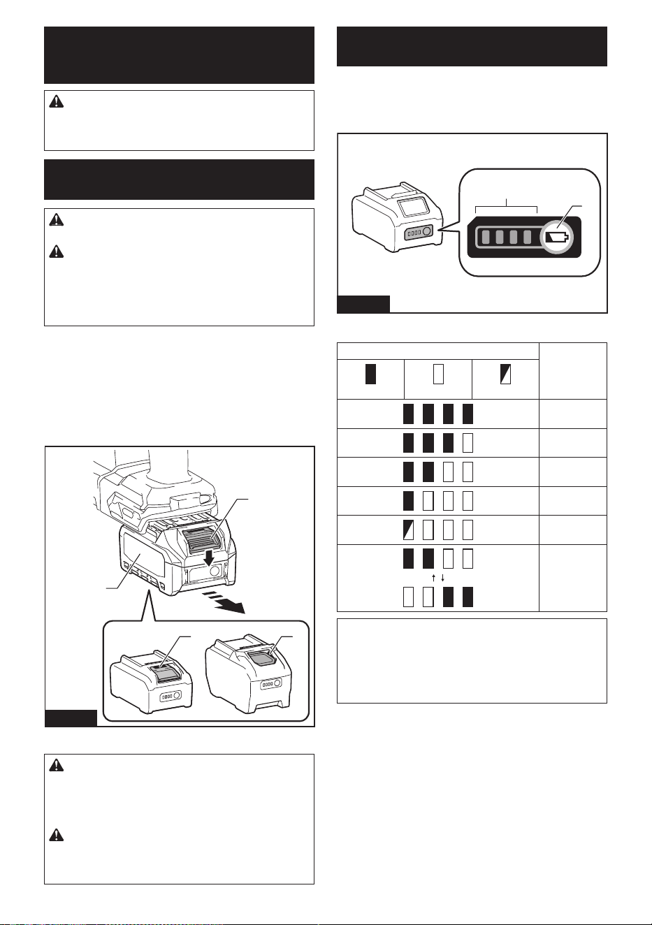
33 ESPAÑOL
DESCRIPCIÓN DEL
FUNCIONAMIENTO
PRECAUCIÓN: Asegúrese siempre de que la
herramienta esté apagada y el cartucho de batería
haya sido extraído antes de realizar cualquier
ajuste o comprobación en la herramienta.
Instalación o extracción del
cartucho de batería
PRECAUCIÓN:
Apague siempre la herramienta
antes de colocar o quitar el cartucho de batería.
PRECAUCIÓN:
Sujete la herramienta y el car-
tucho de la batería con rmeza al colocar o quitar el
cartucho de batería.Sinosesujetaconrmezalaherra-
mientayelcartuchodebatería,puedeocasionarquese
resbalen de sus manos causando daños a la herramienta
yalcartuchodebatería,asícomolesionesalapersona.
Parainstalarelcartuchodebatería,alineelalengüeta
sobreelcartuchodebateríaconlaranuraenlacarcasa
ydeslícelahastasulugar.Insérteloporcompletohasta
quesejeensulugarconunpequeñoclic.Sipuede
verelindicadorrojocomosemuestraenlailustración,
este no ha quedado asegurado por completo.
Paraquitarelcartuchodebatería,deslícelodelaherramienta
mientras desliza el botón sobre la parte delantera del cartucho.
11
2
3
Fig.1
►1.Indicadorrojo2. Botón 3.Cartuchodebatería
PRECAUCIÓN:
Introduzca siempre com-
pletamente el cartucho de batería hasta que el
indicador rojo no pueda verse.Sino,podríaacci-
dentalmente salirse de la herramienta y caer al suelo
causando una lesión a usted o alguien a su alrededor.
PRECAUCIÓN: No instale el cartucho de
batería a la fuerza. Si el cartucho no se desliza al
interior fácilmente, se debe a que no está siendo
insertado correctamente.
Indicación de la capacidad restante
de la batería
Oprimaelbotóndevericaciónenelcartuchodela
bateríaparaqueindiquelacapacidadrestantedela
batería.Laslucesindicadorasseiluminaránporalgu-
nos segundos.
1
2
Fig.2
►1. Luces indicadoras 2.Botóndevericación
Luces indicadoras Capacidad
restante
Iluminadas Apagadas Parpadeando
75% a 100%
50% a 75%
25% a 50%
0% a 25%
Cargar la
batería.
Labatería
pudo haber
funcionado
mal.
NOTA: Dependiendo de las condiciones de uso y
la temperatura ambiente, la indicación podrá diferir
ligeramente de la capacidad real.
NOTA: La primera luz indicadora (extrema izquierda)
parpadeará cuando el sistema de protección de
bateríaestéenfuncionamiento.
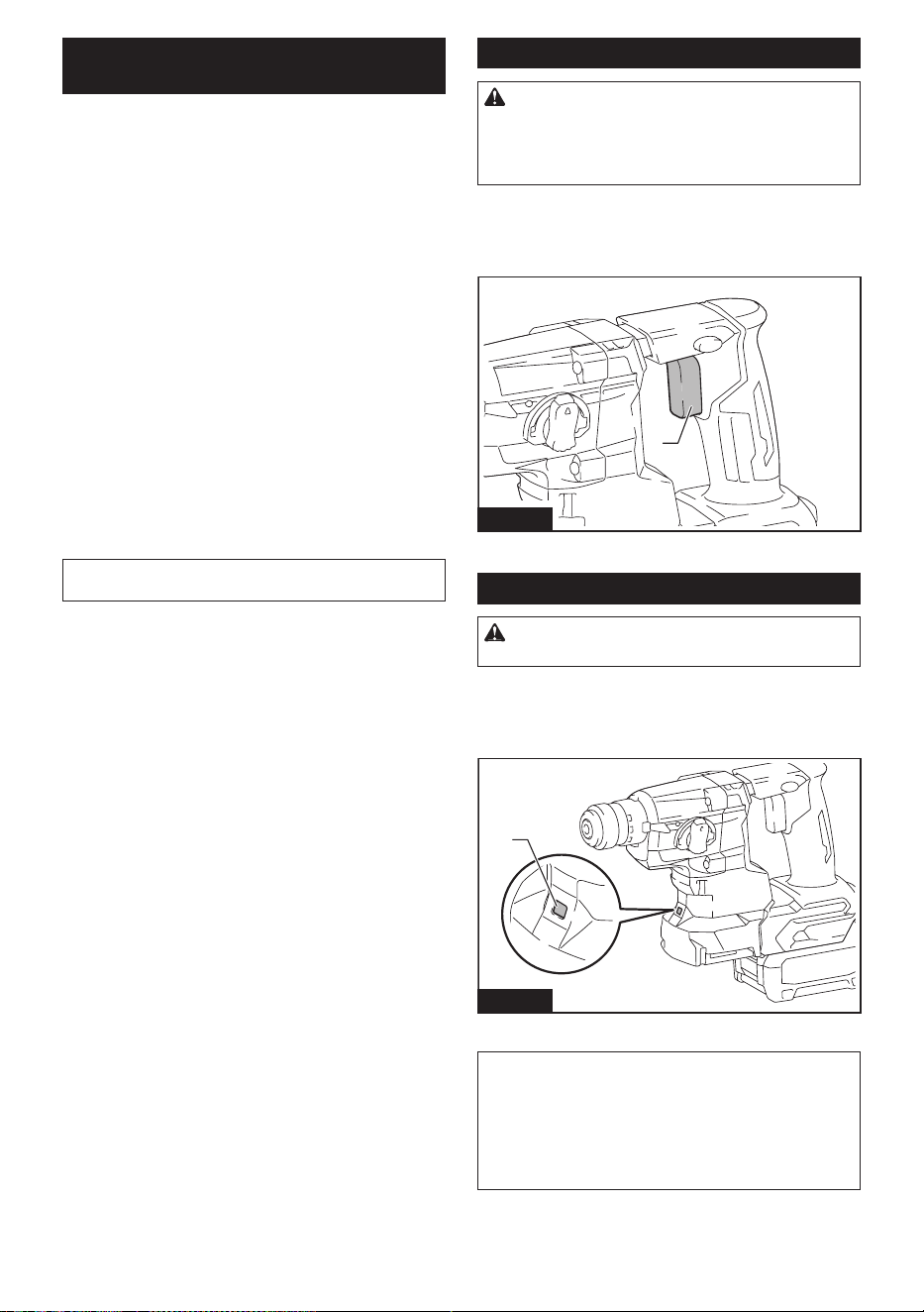
34 ESPAÑOL
Sistema de protección para la
herramienta/batería
La herramienta está equipada con un sistema de pro-
teccióndelaherramienta/batería.Estesistemacorta
enformaautomáticaelsuministrodeenergíaalmotor
paraprolongarlavidaútildelaherramientaylabatería.
La herramienta se detendrá automáticamente durante
laoperaciónsilaherramientaolabateríasesometena
una de las siguientes condiciones:
Protección contra sobrecarga
Cuandolabateríaseestéutilizandodeunamanera
que cause que consuma una cantidad de corriente
anormalmente alta, la herramienta se detendrá automá-
ticamente sin indicación alguna. En este caso, apague
la herramienta y detenga la aplicación que causó que la
herramienta se sobrecargara. Luego encienda la herra-
mienta para reiniciarla.
Protección contra
sobrecalentamiento
Cuandolaherramientaolabateríasesobrecalienten,
la herramienta se detendrá automáticamente. En este
caso,permitaquelaherramientaylabateríaseenfríen
antes de volver a encender la herramienta.
NOTA: Cuando la herramienta se sobrecaliente, la
lámpara parpadeará.
Protección en caso de
sobredescarga
Cuandolacapacidaddelabateríanoessuciente,la
herramienta se detiene automáticamente. En este caso,
retirelabateríadelaherramientaycárguela.
Protección contra otras causas
El sistema de protección también está diseñado para
otrascausasquepodríandañarlaherramienta,yper-
mite que la herramienta se detenga automáticamente.
Siga todos los pasos a continuación para eliminar las
causas cuando la herramienta se haya detenido tempo-
ralmente o se haya detenido durante el funcionamiento.
1. Apague la herramienta, y luego enciéndala nueva-
mente para reiniciarla.
2. Carguela(s)batería(s)oreemplácela(s)con
batería(s)recargada(s).
3. Dejequelaherramientayla(s)batería(s)se
enfríen.
Sinohayningunamejoraalrestaurarelsistemade
protección,comuníqueseconsucentrolocaldeservi-
cio Makita.
Accionamiento del interruptor
ADVERTENCIA: Antes de insertar el car-
tucho de batería en la herramienta, compruebe
siempre y cerciórese de que el gatillo interruptor
se acciona debidamente y que vuelve a la posi-
ción “OFF” (apagado) cuando lo suelta.
Paraarrancarlaherramienta,simplementejaleelgatillo
interruptor. La velocidad de la herramienta aumenta
al incrementar la presión en el gatillo interruptor. Para
detenerla, suelte el gatillo interruptor.
1
Fig.3
►1. Gatillo interruptor
Iluminación de la luz delantera
PRECAUCIÓN: No mire a la luz ni vea a la
fuente de luz directamente.
Jale el gatillo interruptor para encender la luz. La luz
continúailuminándosemientrasseestájalandoel
gatillo interruptor. La luz se apaga aproximadamente 10
segundos tras haber liberado el gatillo interruptor.
1
Fig.4
►1. Luz
NOTA: Utilice un paño seco para quitar la suciedad
de la lente de la lámpara. Tenga cuidado de no rayar
lalentedelalámparayaquelailuminaciónpodría
disminuir.
NOTA: La lámpara delantera no se puede usar mien-
tras el sistema de recolección de polvo (accesorio
opcional) está instalado en la herramienta.
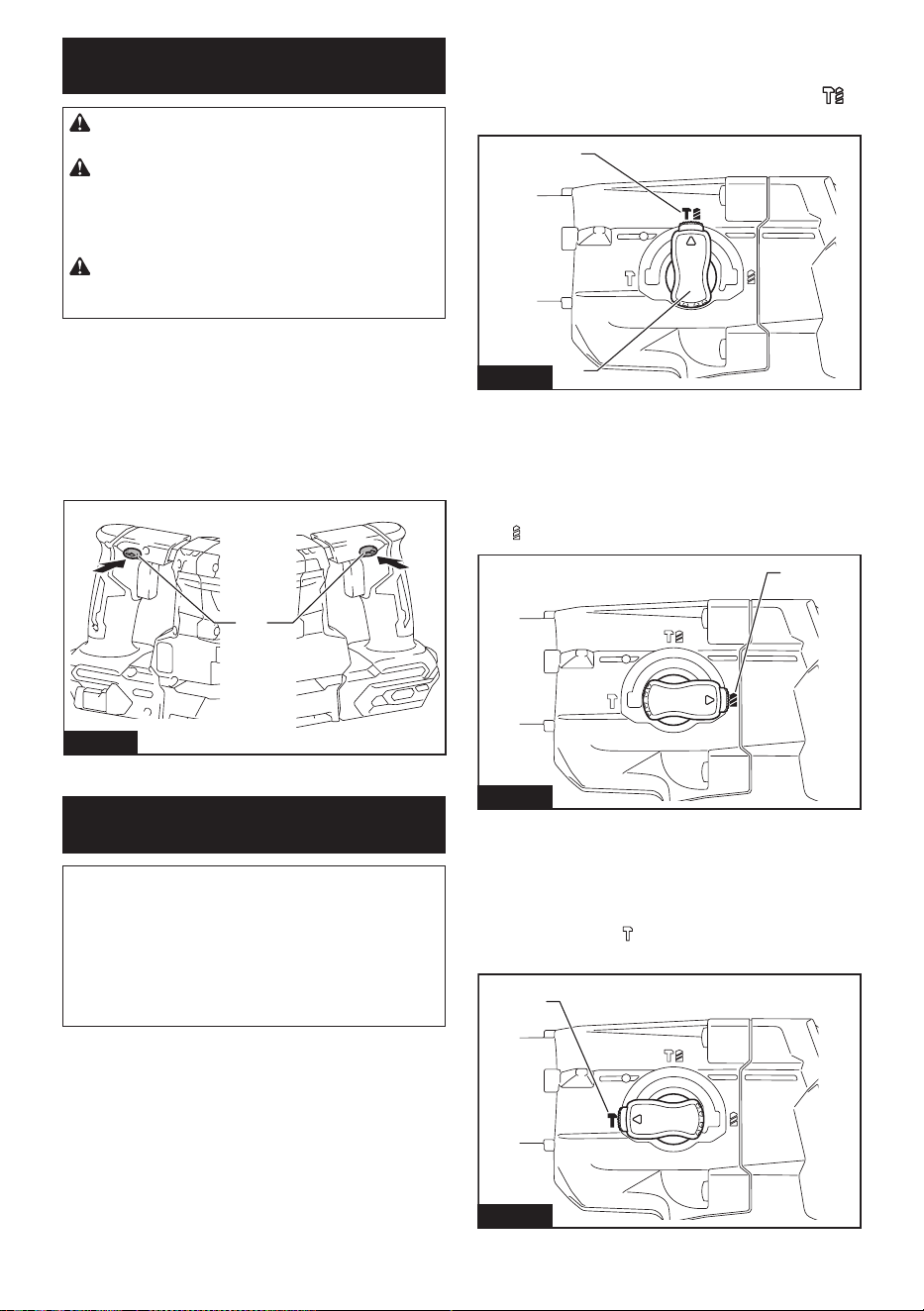
35 ESPAÑOL
Accionamiento del conmutador de
inversión de giro
PRECAUCIÓN: Conrme siempre la direc-
ción de rotación antes de la operación.
PRECAUCIÓN: Utilice el conmutador de
inversión solamente después de que la herra-
mienta haya parado completamente. Si cambia
la dirección de rotación antes de que la herramienta
hayaparadopodríadañarla.
PRECAUCIÓN: Cuando no esté utilizando la
herramienta, ponga siempre la palanca del con-
mutador de inversión en la posición neutral.
Esta herramienta tiene un conmutador de inversión
para cambiar la dirección de rotación. Presione la
palanca del conmutador de inversión desde el lado A
paraunarotaciónensentidodelasmanecillasdelreloj
o desde el lado B, para una rotación en sentido inverso
aldelasmanecillasdelreloj.
Cuando la palanca del conmutador de inversión esté
enlaposiciónneutral,nosepodrájalarelgatillo
conmutador.
1
AB
Fig.5
►1. Palanca del interruptor de inversión
Selección del modo de
accionamiento
AVISO: No gire la perilla de cambio de modo de
accionamiento cuando la herramienta esté en
marcha.Estopodríacausardañosalaherramienta.
AVISO: Para evitar un desgaste rápido del meca-
nismo de cambio de modo, asegúrese siempre
de que la perilla de cambio de modo de acciona-
miento se encuentre realmente ubicada en una de
las tres posiciones del modo de accionamiento.
Rotación con percusión
Parataladrarenconcreto,mampostería,etc.,girelaperi-
lladecambiodemododeaccionamientoalsímbolo .
Utilice una broca de punta de carburo de tungsteno.
1
2
Fig.6
►1. Rotación con percusión 2. Perilla de cambio de
modo de accionamiento
Sólo rotación
Para taladrar en materiales de madera, metal o plástico,
girelaperilladecambiodemododeaccionamientoalsím-
bolo . Utilice una broca helicoidal o broca para madera.
1
Fig.7
►1. Sólo rotación
Sólo percusión
Para operaciones de cincelado, desincrustación o
demolición, gire la perilla de cambio de modo de accio-
namientoalsímbolo . Utilice un cincel de punta,
cincel plano, cincel de desincrustación, etc.
1
Fig.8
►1. Sólo percusión
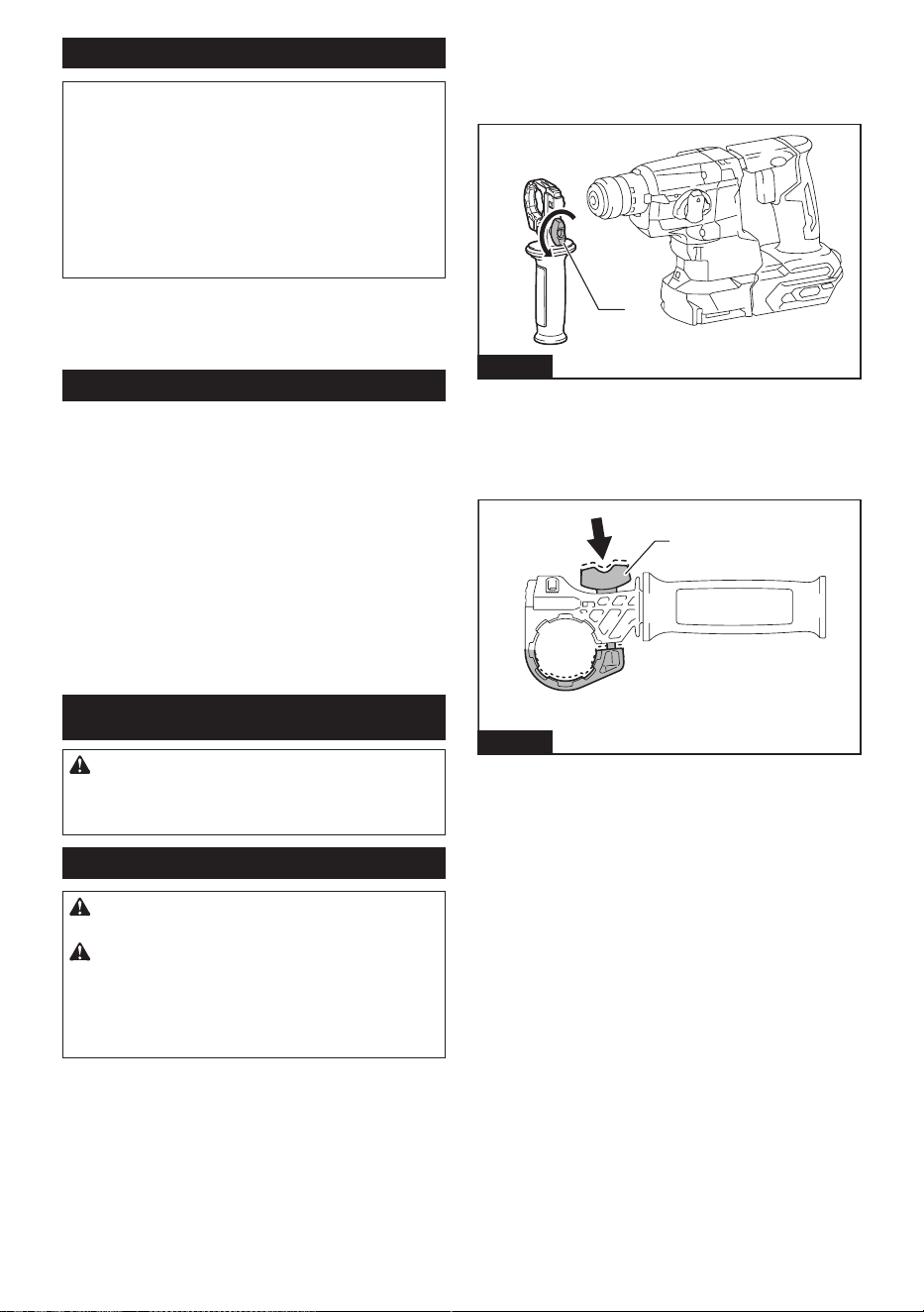
36 ESPAÑOL
Limitador de torsión
AVISO: En cuanto el limitador de torsión se
accione, apague de inmediato la herramienta.
Esto ayudará a evitar el desgaste prematuro de la
herramienta.
AVISO: Las brocas tales como las de sierra
perforadora, las cuales tienden a atorarse o
engancharse fácilmente en el agujero, no son
adecuadas para esta herramienta. Esto es debido
a que pueden provocar que el limitador de torsión se
accione con demasiada frecuencia.
El limitador de torsión se accionará una vez que se
alcance un cierto nivel de torsión. El motor se desen-
gancharádelejedesalida.Cuandoestosuceda,la
brocadejarádegirar.
Funcionamiento electrónico
La herramienta está equipada con funciones electróni-
cas para facilitar la operación.
• Freno eléctrico
Esta herramienta está equipada con un freno
eléctrico. Si de manera consistente la herramienta
no cesa de funcionar rápidamente después de
soltar el gatillo interruptor, lleve la herramienta
a un centro de servicio Makita para que le den
mantenimiento.
• Control de velocidad constante
La función de control de velocidad permite una
rotación constante independientemente de las
condiciones de carga.
MONTAJE
PRECAUCIÓN: Asegúrese siempre de que la
herramienta esté apagada y el cartucho de batería
haya sido extraído antes de realizar cualquier
trabajo en la misma.
Empuñadura lateral (mango auxiliar)
PRECAUCIÓN: Utilice siempre la empuña-
dura lateral para garantizar una operación segura.
PRECAUCIÓN: Después de instalar o ajustar
la empuñadura lateral, asegúrese de que la empu-
ñadura lateral esté asegurada rmemente con las
protuberancias de la herramienta completamente
acopladas por las ranuras de la empuñadura
lateral.
Para instalar la empuñadura lateral, siga los pasos a
continuación.
1. Aojeeltornillodemariposaenlaempuñadura
lateral.
1
Fig.9
►1. Tornillo de mariposa
2. Instale la empuñadura lateral de modo que las
ranurasenlaempuñaduraencajenenlasprotuberan-
cias de la herramienta mientras se oprime el tornillo de
mariposa.
1
Fig.10
►1. Tornillo de mariposa
3. Apriete el tornillo de mariposa para asegurar
laempuñadura.Laempuñadurapuedejarseenel
ángulo deseado.
Paraquitarlaempuñaduralateral,aojeeltornillode
mariposa de la empuñadura lateral. Retire la empuña-
dura lateral de la herramienta.
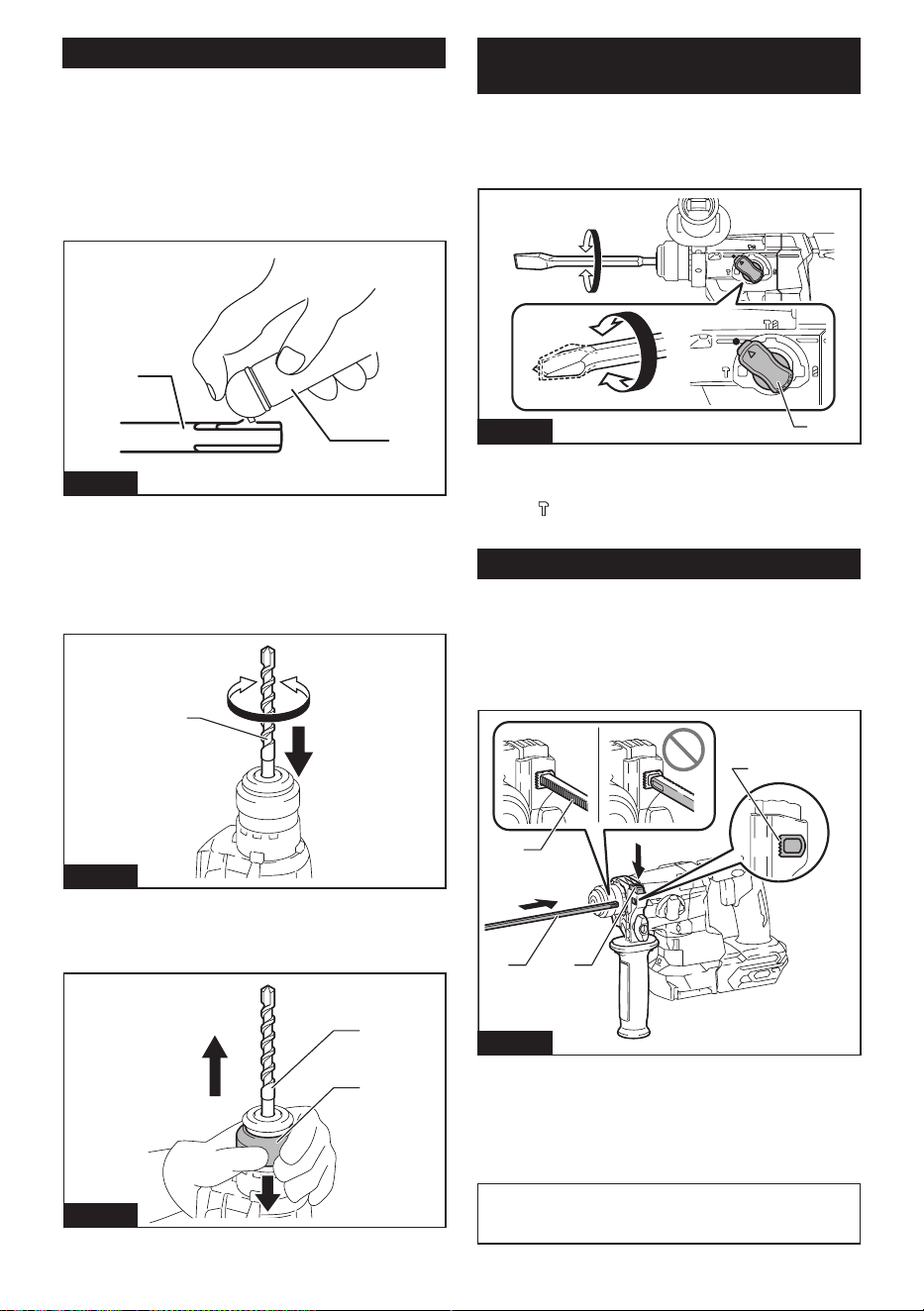
37 ESPAÑOL
Instalación o extracción de la broca
Grasa
Limpie el extremo de la espiga de la punta y aplique
grasa antes de instalar la punta.
Aplique previamente una pequeña cantidad de grasa
(alrededor de 0,5 g - 1 g) en el extremo de la espiga
de la punta. La lubricación del portabrocas asegura un
accionamiento suave y una vida útil más larga.
1
2
Fig.11
►1. Extremo de la espiga 2. Grasa
Inserte la broca en la herramienta. Gire la broca y
empújelahaciaadentrohastaquequedeenganchada.
Después de instalar la broca, asegúrese siempre de
que la broca quede asegurada en su lugar intentando
jalarlahaciaafuera.
1
Fig.12
►1. Broca
Paraextraerlabroca,empujehastaabajolacubierta
delportabrocasyjalelabrocahaciaafuera.
1
2
1
2
Fig.13
►1. Broca 2. Cubierta del portabrocas
Ángulo del cincel (durante el cincelado,
desincrustación o demolición)
Elcincelpuedejarseenelángulodeseado.Para
cambiar el ángulo del cincel, gire la perilla de cambio de
mododeaccionamientoalsímboloO.Gireelcincelal
ángulo deseado.
1
Fig.14
►1. Perilla de cambio de modo de accionamiento
Gire la perilla de cambio de modo de accionamiento al
símbolo
. Luego asegúrese de que el cincel quede
asegurado en su lugar girándolo ligeramente.
Calibrador de profundidad
Elcalibradordeprofundidadsirveparaperforaroricios
de profundidad uniforme.
Oprima y mantenga oprimido el botón de bloqueo y
luegoinserteelcalibradordeprofundidadeneloricio.
Asegúrese de que el lado dentado del calibrador de
profundidad quede de frente a la marca.
3
1 2
4
Fig.15
►1. Calibrador de profundidad 2. Botón de bloqueo
3. Marca 4. Lado dentado
Ajusteelcalibradordeprofundidadmoviéndolohacia
atrás y hacia adelante mientras oprime el botón de blo-
queo.Despuésdeajustarlo,suelteelbotóndebloqueo
para bloquear el calibrador de profundidad.
NOTA: Asegúrese de que el calibrador de profundi-
dad no toque el cuerpo principal de la herramienta al
momentodejarlo.
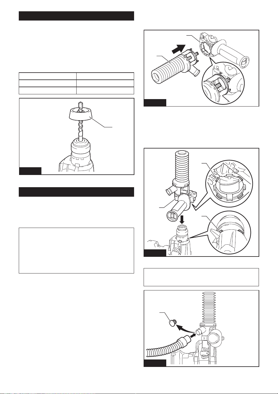
38 ESPAÑOL
Contenedor de polvo
Accesorio opcional
Utilice el contenedor de polvo para evitar que el polvo
caiga sobre la herramienta y sobre usted al realizar
operaciones de perforación por encima de su cabeza.
Fijeelcontenedordepolvoenlapuntatalcomose
muestra en la ilustración. El tamaño de las puntas en
lasqueelcontenedordepolvopuedejarseeselque
se indica a continuación.
Modelo Diámetro de la punta
Contenedor de polvo 5 6mm(1/4″)-14,5mm(9/16″)
Contenedor de polvo 9 12mm(15/32″)-16mm(5/8″)
1
Fig.16
►1. Contenedor de polvo
Juego contenedor de polvo
Accesorio opcional
Instalación del juego contenedor de
polvo
AVISO: No utilice el juego contenedor de polvo
cuando perfore en metal o un material similar.
Estopodríadañareljuegocontenedordepolvo
debidoalcalorproducidoporlaspequeñaspartículas
de metal o material similar. No instale ni extraiga el
juegocontenedordepolvoconlabrocainstaladaen
laherramienta.Estopodríadañareljuegocontene-
dordepolvoycausarlaltracióndepolvo.
Antesdeinstalareljuegocontenedordepolvo,extraiga
la broca de la herramienta en caso de estar instalada.
1. Aojeeltornillodemariposaenlaempuñadura
lateral.
2. Instaleeljuegocontenedordepolvodemodoque
laspartessalientesdelcontenedordepolvoencajenen
las hendiduras de la empuñadura lateral.
2
1
Fig.17
►1. Juego contenedor de polvo 2. Empuñadura
lateral
3. Instale la empuñadura lateral de modo que la
ranuraenlaempuñaduraencajeenlaprotuberancia
de la herramienta. Apriete el tornillo de mariposa para
asegurar la empuñadura lateral.
1
2
3
Fig.18
►1. Empuñadura lateral 2. Ranura 3. Protuberancia
NOTA:Siconectaunaaspiradoraaljuegocontene-
dor de polvo, retire la tapa guardapolvos antes de
conectar la aspiradora.
1
Fig.19
►1. Tapa guardapolvos
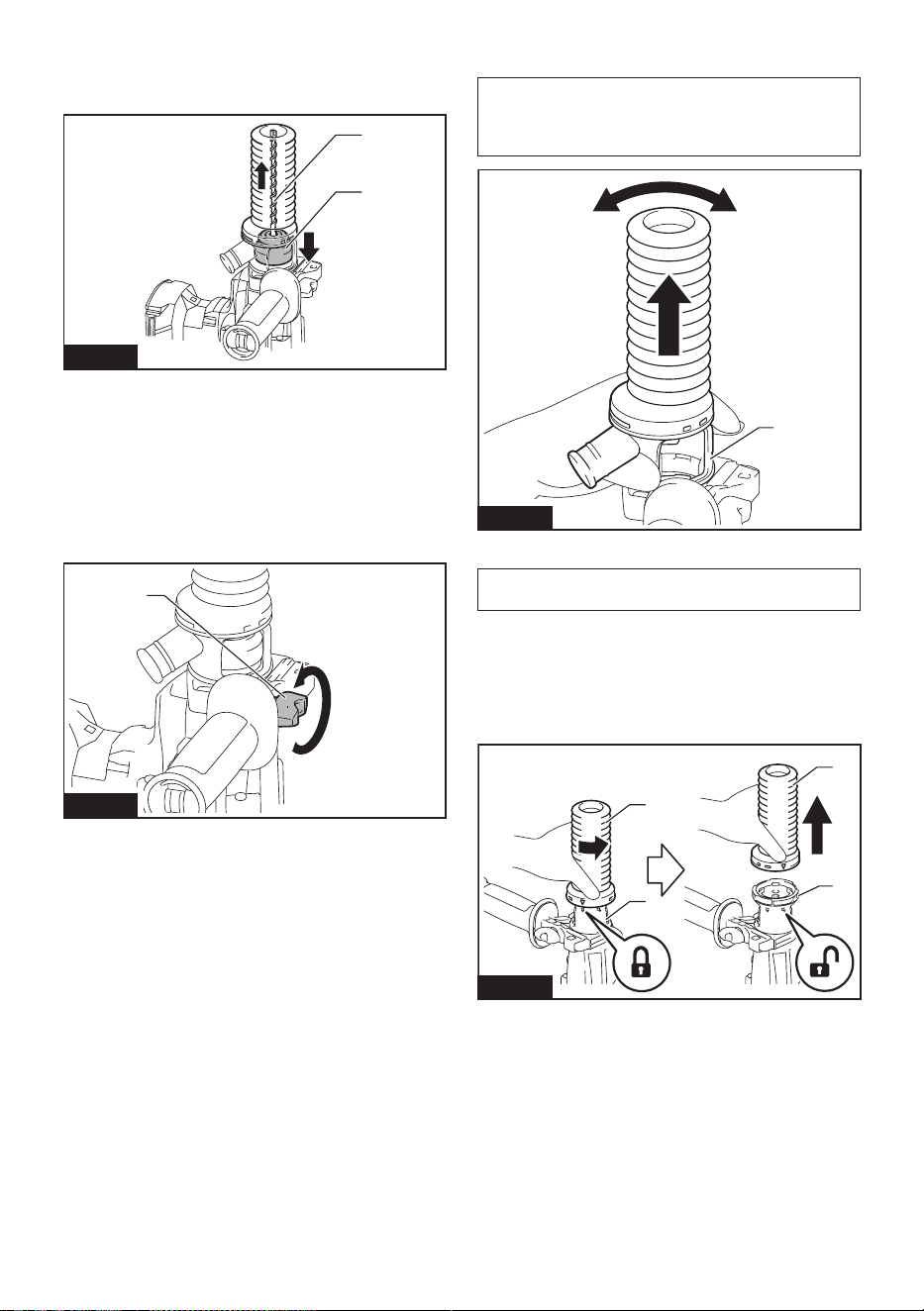
39 ESPAÑOL
Extracción de la broca
Paraextraerlabroca,jalehastaabajolacubiertadel
portabrocasyjalelabrocahaciaafuera.
1
2
Fig.20
►1. Broca 2. Cubierta del portabrocas
Extracción del juego contenedor de
polvo
Paraextraereljuegocontenedordepolvo,sigalos
pasos a continuación.
1. Aojeeltornillodemariposadelaempuñadura
lateral. Retire la empuñadura lateral de la herramienta.
1
Fig.21
►1. Tornillo de mariposa
2. Sostengalaraízdelcontenedordepolvoy
sáquelo hacia afuera.
NOTA:Sileresultadifícilextraereljuegocontenedor
de polvo, retire las partes salientes del contenedor
depolvounaporunamoviendoyjalandolaraízdel
contenedor de polvo.
1
Fig.22
►1. Contenedor de polvo
NOTA:Sisesalelatapadeljuegocontenedorde
polvo, colóquela nuevamente en la posición original.
Para volver a colocar la tapa en su posición original,
siga los pasos a continuación.
1. Gire el fuelle en sentido inverso al de las mane-
cillasdelreloj,yretírelodelaunidaddejacióndel
juegocontenedordepolvomientraselfuelleestá
desbloqueado.
1
2
1
2
Fig.23
►1. Fuelles 2.Unidaddejación
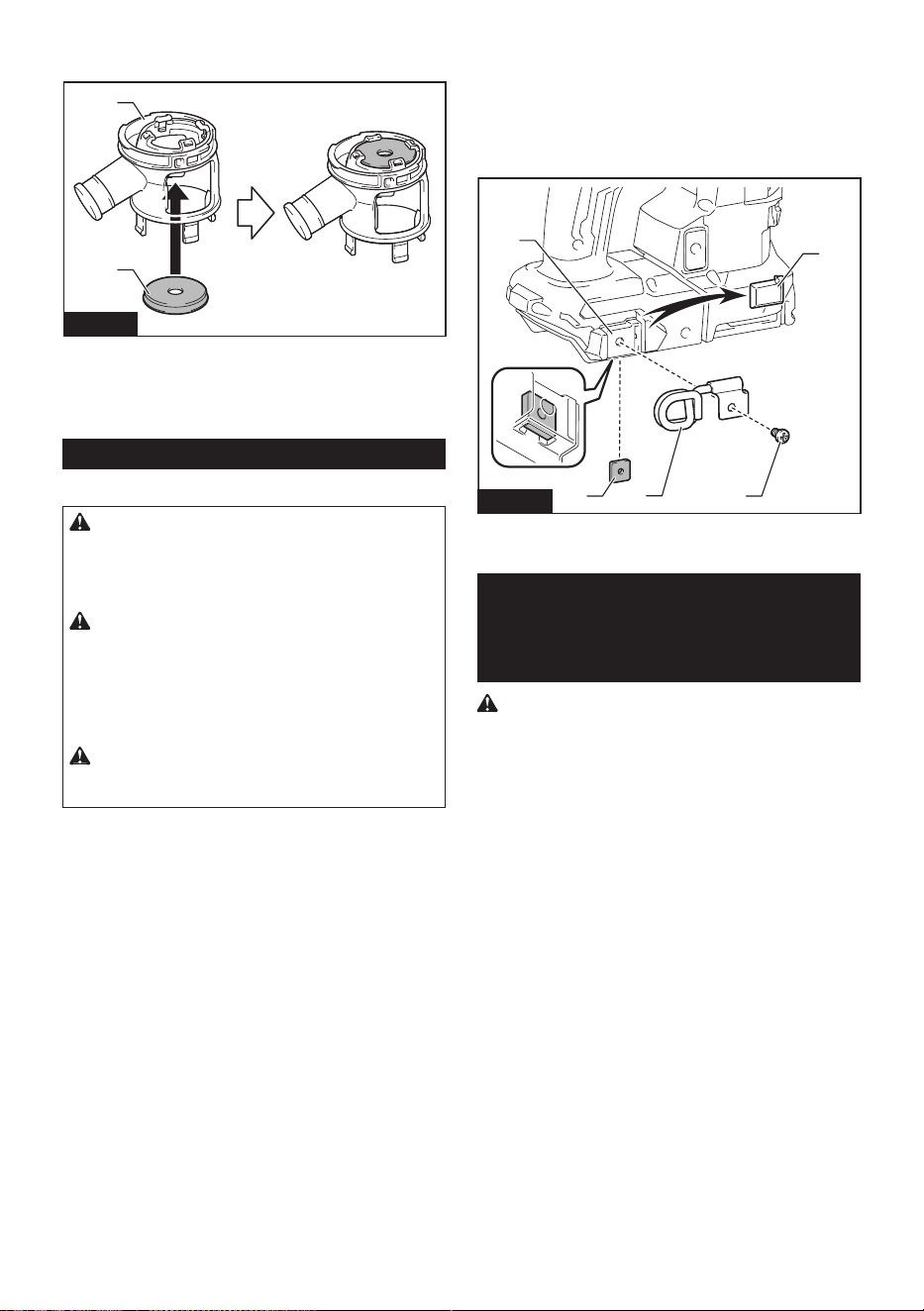
40 ESPAÑOL
2. Ponga la tapa nuevamente en su sitio, con el lado
con letras orientado hacia arriba.
1
2
Fig.24
►1. Tapa 2.Unidaddejación
3. Asegúrese de que las ranuras alrededor de la
tapaajustenbienenlosrebordesdelaaberturasupe-
riordelaunidaddejación.
Colgador de la herramienta
Accesorio opcional
PRECAUCIÓN: No utilice el colgador de
la herramienta y el tornillo cuando estos estén
dañados. Antes de usarlos, verique la existencia
de daños, roturas o deformaciones y asegúrese
de que el tornillo esté apretado.
PRECAUCIÓN: Instale o extraiga el colgador
de la herramienta sobre una mesa o supercie
estables. Asegúrese de usar el tornillo pro-
porcionado con el colgador de la herramienta
solamente. Después de instalar el colgador de la
herramienta, asegúrese de que este quede bien
asegurado con el tornillo.
PRECAUCIÓN: No extraiga el cartucho de la
batería mientras cuelga la herramienta. La herra-
mientapodríacaersieltornillonoestáapretado.
El colgador de la herramienta está diseñado para
conectar el cordel de seguridad (correa de amarre).
Antes de instalar el colgador de la herramienta, retire la
tapadegomadeloricioparatornilloenelsoportede
montaje.Insertelatuercacuadradadebajodelsoporte.
Apriete el colgador de la herramienta con el tornillo en
su lugar.
1
2
3
5
4
Fig.25
►1. Tapa de goma 2.Soportedemontaje3. Tuerca
cuadrada 4. Colgador de la herramienta 5. Tornillo
Advertencias de seguridad sobre la
conexión del cordel de seguridad
(correa de amarre) al colgador de la
herramienta
Advertencias de seguridad especícas para uso
en alturas
Lea todas las advertencias de seguridad e instruc-
ciones. El no seguir las advertencias e instrucciones
podríaocasionarlesionesgraves.
1. Mantenga siempre la herramienta atada
cuando trabaje “en alturas”. La longitud
máxima del cordel es de 2 m (6,5 ft).
La altura de caída máxima permisible para
el cordel de seguridad (correa de amarre) no
deberá superar los 2 m (6,5 ft).
2. No ancle el cordel de la herramienta a nada
en su cuerpo o a componentes móviles. Ancle
el cordel de la herramienta a una estructura
rígida que pueda soportar las fuerzas de una
herramienta en caída.
3. Asegúrese de que el cordel esté debidamente
asegurado de cada extremo previo al uso.
4. Inspeccione la herramienta y el cordel antes
de cada uso para ver que no tengan daños y
que funcionen correctamente (incluyendo la
tela y las puntadas). No los utilice si presentan
daños o no funcionan correctamente.
5. No envuelva cordeles alrededor de bordes
losos o ásperos ni permita que estos entren
en contacto con ellos.
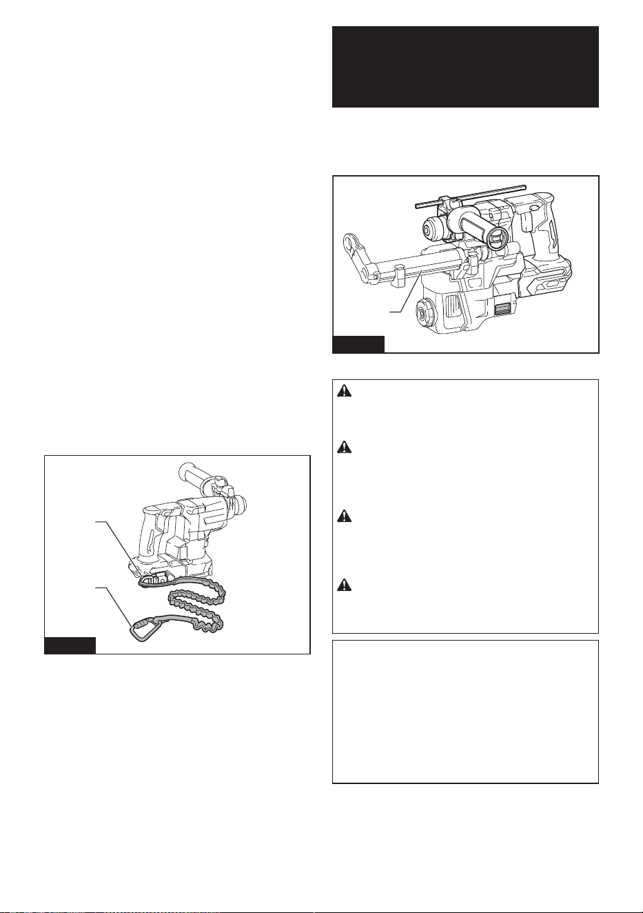
41 ESPAÑOL
6. Asegure el otro extremo del cordel fuera del
área de trabajo de manera que la herramienta
en caída esté rmemente sujetada.
7. Fije el cordel de forma que la herramienta se
mueva lejos del operador en caso de que esta
se caiga.Lasherramientasencaídasebalan-
cean en el cordel, lo que puede ocasionar lesio-
nes o la pérdida del equilibrio.
8. No la utilice cerca de piezas móviles o maqui-
naria funcionando.Elhacerlopodríaocasionar
riesgo de choque o enredo.
9. No transporte la herramienta sujetándola del
dispositivo de atadura o el cordel.
10. Cargue la herramienta únicamente entre sus
manos mientras mantenga bien el equilibrio.
11. No sujete cordeles de seguridad a la herra-
mienta de manera que evite que los interrupto-
res o el bloqueo para el gatillo (de ser suminis-
trado) funcionen correctamente.
12. Evite enredarse en el cordel.
13. Mantenga el cordel de seguridad alejado del
área de perforación de la herramienta.
14. Use una carabina de bloqueo (de tipo multiac-
ción y de seguro de rosca). No use carabinas
de tipo acción única con gancho de resorte.
15. En caso de que la herramienta llegue a caerse,
esta debe etiquetarse, sacarse de servicio y
ser inspeccionada por una fábrica o centro de
servicio autorizado Makita.
16. No cuelgue la herramienta en su cintura. La
herramientacalienteysuaccesoriopodríantocar
su piel y causar quemaduras.
2
1
Fig.26
►1. Colgador de la herramienta 2. Cordel de seguri-
dad (correa de amarre)
SISTEMA DE
RECOLECCIÓN DE
POLVO
Accesorio opcional
El sistema de recolección de polvo está diseñado para
recolectarpolvoconecaciacuandorealizalaopera-
ción de perforación en concreto.
1
Fig.27
►1. Sistema de recolección de polvo
PRECAUCIÓN: El sistema de recolección de
polvo está diseñado para perforar en concreto
únicamente. No utilice el sistema de recolección
de polvo para perforar en metal ni en madera.
PRECAUCIÓN: Cuando vaya a utilizar la
herramienta con el sistema de recolección de
polvo, asegúrese de colocar el ltro en el sistema
de recolección de polvo para evitar la inhalación
de polvo.
PRECAUCIÓN: Antes de utilizar el sistema
de recolección de polvo, compruebe que el ltro
no esté dañado y que el tubo interior no tenga
polvo ni materias extrañas.Elnohacerlopodría
causar la inhalación de polvo.
PRECAUCIÓN: El sistema de recolección
de polvo recolecta el polvo que se genera en un
volumen considerable, sin embargo, es imposible
recolectarlo todo.
AVISO: No utilice el sistema de recolección de
polvo para taladrado con corona ni cincelado.
AVISO: No utilice el sistema de recolección
de polvo para metal o madera. El sistema de
recolección de polvo está diseñado para concreto
únicamente.
AVISO: No utilice el sistema de recolección de
polvo para perforar en concreto húmedo ni lo
utilice en entornos mojados. El hacerlo podría
causar averías.
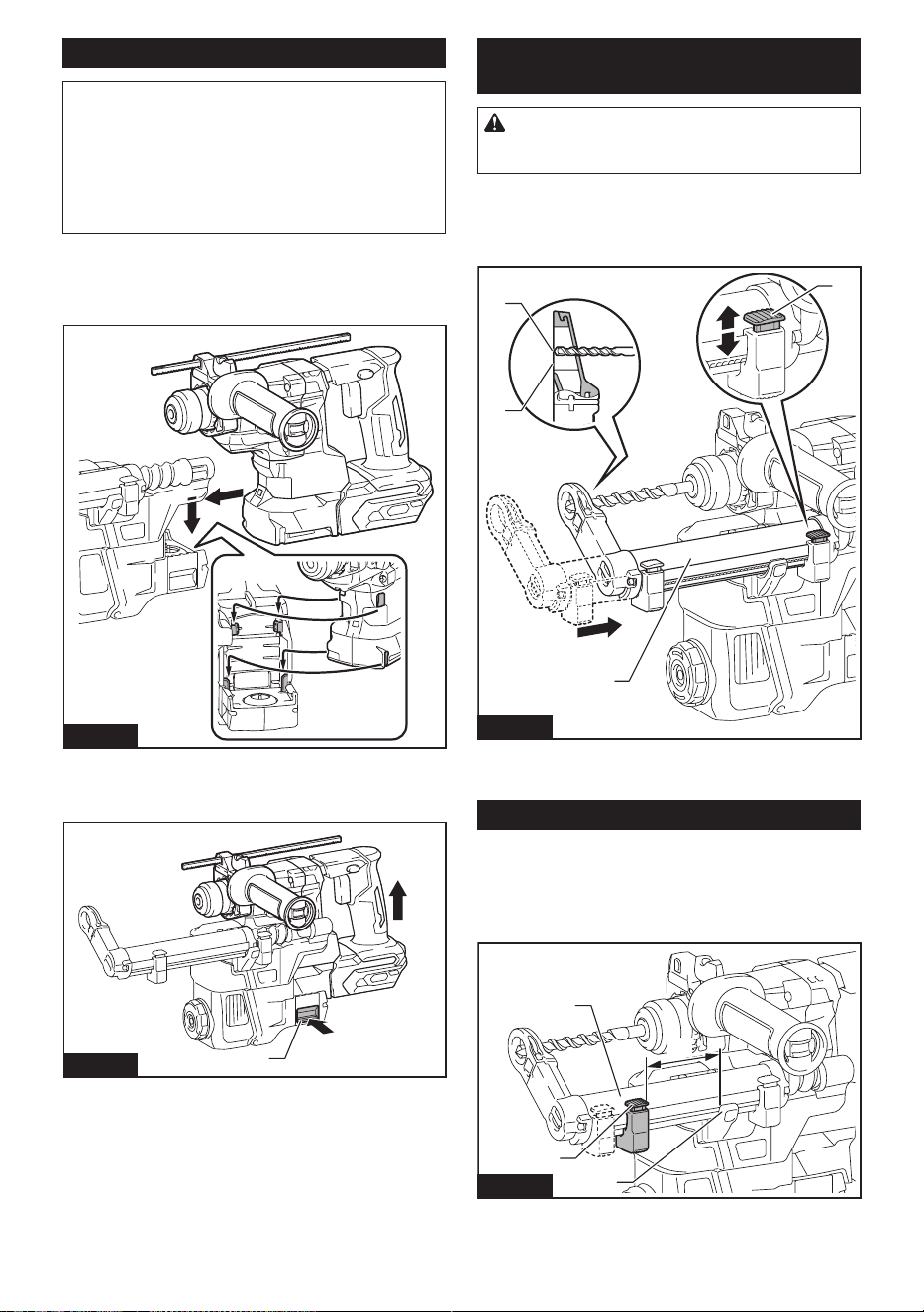
42 ESPAÑOL
Instalación o extracción
AVISO: Antes de instalar el sistema de recolec-
ción de polvo, limpie las partes de unión de la
herramienta y el sistema de recolección de polvo.
Las materias extrañas en las partes de unión pueden
dicultarlainstalacióndelsistemaderecolecciónde
polvo. Si queda polvo en el conducto de aire, el polvo
entraenlaherramientaycausaunatascoenelujo
deaireolaaveríadelaherramienta.
Para instalar el sistema de recolección de polvo, inserte
la herramienta completamente dentro del sistema de
recolección de polvo hasta que la herramienta quede
asegurada en su lugar con un clic pequeño.
Fig.28
Paraextraerelsistemaderecoleccióndepolvo,jale
hacia arriba la herramienta mientras oprime el botón de
desbloqueo.
1
Fig.29
►1. Botón de desbloqueo
Ajuste de la posición de la boquilla
del sistema de recolección de polvo
PRECAUCIÓN: No apunte la boquilla hacia
usted o a otros cuando libere la boquilla opri-
miendo el botón de ajuste de la guía.
Deslicehaciaadentroyhaciaafueralaguíaparalaboquilla
mientraspresionaelbotóndeajustedelaguía,yluegosuelte
el botón en una posición exacta donde la punta de la broca se
encuentrejustodetrásdelasuperciefrontaldelaboquilla.
1
2
3
4
Fig.30
►1.Guía2.Botóndeajustedelaguía3. Punta de la
broca 4.Superciefrontaldelaboquilla
Ajuste de las profundidades de perforación
Laprofundidaddeperforaciónsepuedeajustar
cambiandolaslongitudesentreelbotóndeajustede
profundidadyelbrazodesoportedelaguíaparala
boquilla.Mantengapresionadoelbotóndeajustede
profundidad,ydeslíceloalaposicióndeseada.
4
3
1
2
Fig.31
►1.Botóndeajustedeprofundidad2.Guíapara
la boquilla 3.Brazodesoportedelaguíaparala
boquilla 4. Profundidades de perforación
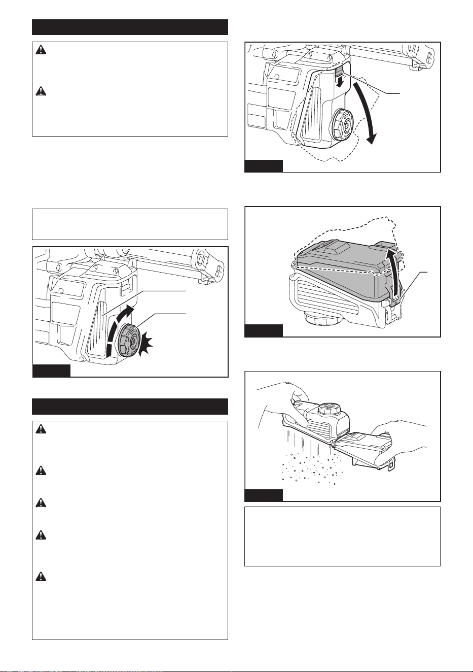
43 ESPAÑOL
Sacudir el polvo del ltro
PRECAUCIÓN: No gire el selector de la caja
para polvo mientras la caja para polvo se extrae
del sistema de recolección de polvo. De lo contra-
rio puede ocasionarse la inhalación de polvo.
PRECAUCIÓN: Apague siempre la herra-
mienta antes de girar el selector de la caja para
polvo. Si se gira el selector mientras la herramienta
está en funcionamiento, se puede ocasionar la pér-
dida del control de la herramienta.
Sisesacudeelpolvodelltroenelinteriordelacaja
parapolvo,sepuedemantenerlaecienciadeaspira-
ción y reducir además el número de veces que hay que
desechar el polvo.
Giretresveceselselectordelacajaparapolvocada
vez que se acumulen 50 000 mm
3
de polvo o cuando
crea que el rendimiento de aspiración se ha reducido.
NOTA: 50 000 mm
3
de polvo equivalen a perforar
10oriciosdeø10mmy65mmdeprofundidad(14
oriciosdeø3/8″y2″deprofundidad).
1
2
Fig.32
►1.Cajaparapolvo2. Selector
Eliminación del polvo
PRECAUCIÓN: Asegúrese siempre de que la
herramienta esté apagada y el cartucho de batería
haya sido extraído antes de realizar cualquier
trabajo en la misma.
PRECAUCIÓN: Cuando vaya a proceder a
eliminar el polvo, asegúrese de usar una máscara
contra polvo.
PRECAUCIÓN: Asegúrese de que la herra-
mienta esté completamente detenida al desechar
el polvo.
PRECAUCIÓN: Vacíe la caja para polvo regu-
larmente antes de que ésta se llene. El no hacerlo
podríareducireldesempeñodelarecolecciónde
polvo y causar la inhalación de polvo.
PRECAUCIÓN: El desempeño de la recolec-
ción de polvo se verá reducido si el ltro en la
caja para polvo llega a obstruirse. Como referen-
cia, reemplace el ltro con uno nuevo después de
aproximadamente 200 veces que la caja se haya
llenado de polvo.Elnohacerlopodríacausarla
inhalación de polvo.
1. Extraigalacajaparapolvomientraspresiona
haciaabajolapalancadelacajaparapolvo.
1
Fig.33
►1. Palanca
2. Abralacubiertadelacajaparapolvo.
1
Fig.34
►1. Cubierta
3. Elimineelpolvoyluegolimpieelltro.
Fig.35
AVISO: Cuando limpie el ltro, golpee suave-
mente la caja del ltro con la mano para eliminar
el polvo. No golpee el ltro directamente; evite
tocarlo con un cepillo u objeto similar, ni sople
aire comprimido al ltro. El hacerlo podría dañar
el ltro.
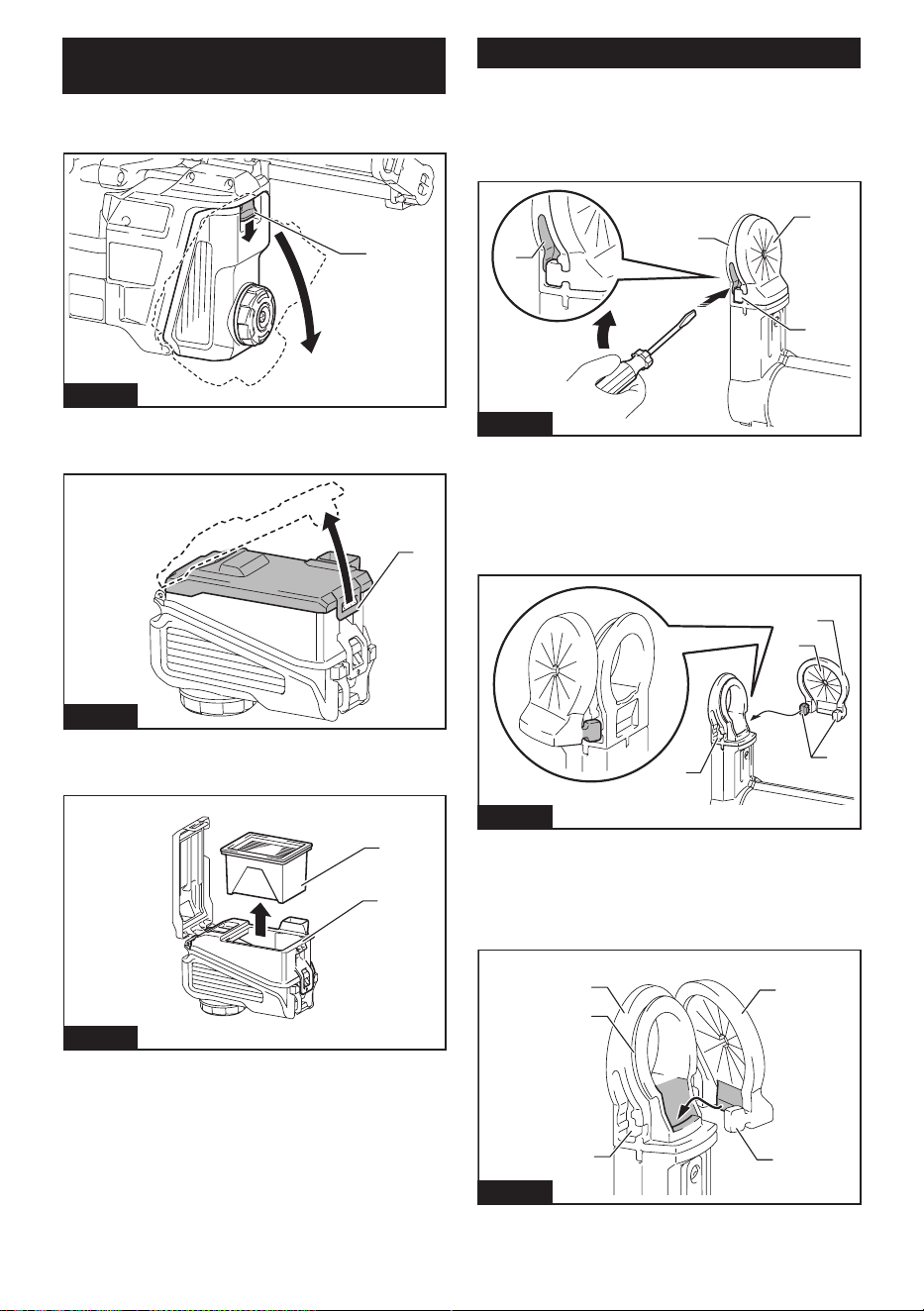
44 ESPAÑOL
Reemplazo del ltro de la caja para
polvo
1. Extraigalacajaparapolvomientraspresiona
haciaabajolapalancadelacajaparapolvo.
1
Fig.36
►1. Palanca
2. Abralacubiertadelltrodelacajaparapolvo.
1
Fig.37
►1.Cubiertadelltro
3. Extraigaelltrodelacajadelltro.
1
2
Fig.38
►1. Filtro 2.Cajadelltro
4. Coloqueunltronuevoenlacajadelltroyluego
jelacubiertadelltro.
5. Cierrelacubiertadelacajaparapolvoyluego
fíjelaenelsistemaderecoleccióndepolvo.
Reemplazo del tapón sellador
1.
Inserte un destornillador de punta plana en una de las ranuras
colocadas a los lados del cabezal de la boquilla. Incline el destorni-
llador de punta plana en un ángulo para apretar y sacar el gancho
cúbico del tapón sellador. Posteriormente, pele el borde de goma del
tapónselladordelacejadelaaberturadelcabezaldelaboquilla.
1
2
3
4
Fig.39
►1. Tapón sellador 2. Gancho cúbico 3. Ranura
4. Cabezal de la boquilla
2. Coloque uno de los ganchos cúbicos de un tapón
sellador nuevo en la parte inferior de la ranura en el
cabezaldelaboquillaconunasuperciecóncavadel
tapón sellador orientada hacia adelante.
1
2
4
3
Fig.40
►1. Ganchos cúbicos 2. Parte inferior de la ranura
3. Tapón sellador 4.Superciecóncava
3. Coloque el otro gancho dentro del lado opuesto,
mientras vuelve a colocar el tapón sellador para que
ajusteexactoconlacabezadelaboquilla.
2
1
3
4
5
Fig.41
►1. Tapón sellador 2. Gancho cúbico 3. Parte inferior
de la ranura 4. Cabezal de la boquilla 5.Cejas
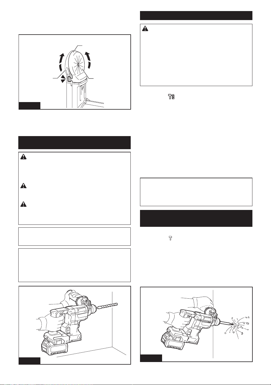
45 ESPAÑOL
4. Ponga con cuidado el borde de goma del tapón
selladorreposandosobrelacejadelaaberturadel
cabezal de la boquilla, de la parte inferior a la parte
superior.
1
2
3
Fig.42
►1. Borde de goma 2. Tapón sellador 3. Cabezal de
la boquilla
OPERACIÓN
PRECAUCIÓN: Utilice siempre la empuña-
dura lateral (mango auxiliar) y sujete rmemente
la herramienta tanto de la empuñadura lateral
como del mango del interruptor durante las
operaciones.
PRECAUCIÓN: Asegúrese siempre de que
la pieza de trabajo quede asegurada antes de la
operación.
PRECAUCIÓN: No jale hacia afuera la herra-
mienta con demasiada fuerza aun si la punta
se atora. La pérdida de control podría causar
lesiones.
AVISO: Antes de utilizar el sistema de recolec-
ción de polvo con la herramienta, lea la sección
sobre el sistema de recolección de polvo.
NOTA:Sielcartuchodebateríaseencuentraabaja
temperatura,laherramientapodríanoalcanzarsu
máxima capacidad. En este caso, caliente el cartucho
debateríausandolaherramientasincargadurante
unratoandelograrquelaherramientaalcancesu
máxima capacidad.
Fig.43
Operación de taladrado con percusión
PRECAUCIÓN:
En el momento de comenzar a
penetrar,cuandoseobstruyeeloricioconvirutasy
partículas,ocuandosetopacontravarillasderefuerzo
deconcreto,seejerceunatremendayrepentina
fuerza de torsión sobre la herramienta/broca. Utilice
siempre la empuñadura lateral (mango auxiliar) y
sujete rmemente la herramienta tanto de la empu-
ñadura lateral como del mango del interruptor
durante las operaciones. El no hacerlo puede provo-
car la pérdida de control de la herramienta y potencial-
mente ocasionar lesiones graves.
Ajustelaperilladecambiodemododeaccionamiento
enelsímbolo .
Coloquelabrocadondedeseehacerelagujeroyluego
jaleelgatillointerruptor.
Aplique fuerza de alimentación al mango del interruptor
(mangoprincipal)paratrabajarconprecisiónyecien-
cia,ysujetelaempuñaduralateral(mangoauxiliar)
para mantener el equilibrio de la herramienta.
Mantenga la herramienta en posición y evite que se
desliceysesalgadelagujero.
Noapliquemáspresióncuandoelagujeroseobstruya
conastillasopartículas.Envezdeesto,hagafuncionar
la herramienta sin presión y luego retire parcialmente
labrocadelagujero.Repitiendoestovariasveces,el
agujeroselimpiaráysepodráreanudareltaladradode
manera normal.
NOTA: Es posible que se produzca excentricidad en
la rotación de la broca al operar la herramienta sin
carga. La herramienta se centrará automáticamente
durante la operación. Esto no afectará la precisión en
el taladrado.
Cincelado/desincrustación/
demolición
Ajustelaperilladecambiodemododeaccionamiento
enelsímbolo .
Sujetelaherramientarmementeconambasmanos.
Encienda la herramienta.
Aplique fuerza de alimentación al mango del interruptor
(mangoprincipal)paratrabajarconprecisiónyecien-
cia,ysujetelaempuñaduralateral(mangoauxiliar)
para mantener el equilibrio de la herramienta.
Aplicar mucha presión sobre la herramienta no incre-
mentarálaeciencia.
Fig.44
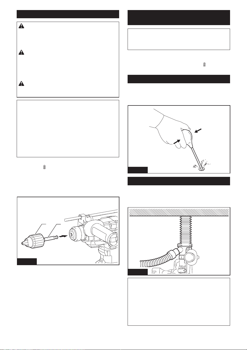
46 ESPAÑOL
Taladrado en madera o metal
PRECAUCIÓN: Sujete rmemente la herra-
mienta y tenga cuidado cuando la broca de tala-
dro comience a penetrar en la pieza de trabajo. La
fuerzaejercidaenlaherramienta/brocadetaladroal
momento de la penetración es enorme.
PRECAUCIÓN: Para extraer una broca de
taladro atorada, basta simplemente con ajustar el
interruptor de inversión en rotación inversa para
hacerla retroceder. Sin embargo, la herramienta
puede retroceder bruscamente si no la sujeta con
rmeza.
PRECAUCIÓN: Asegure siempre las piezas
de trabajo con un tornillo de banco o dispositivo
de sujeción similar.
AVISO: Nunca use la “rotación con percusión”
cuando el portabrocas adaptador esté instalado
en la herramienta.Estopodríacausardañosal
portabrocas adaptador.
Asimismo,elportabrocasadaptadorpodríasalirseal
invertir la rotación de la herramienta.
AVISO: Ejercer una presión excesiva sobre la
herramienta no hará que consiga taladrar más
rápido. De hecho, una presión excesiva sólo logrará
dañar la punta de la broca de taladro, reducir el des-
empeño y acortar la vida útil de la herramienta.
Ajustelaperilladecambiodemododeaccionamiento
enelsímbolo .
Fijeeladaptadordemandrilenunportabrocasadapta-
dor sin llave en el que pueda instalarse un tornillo que
mida1/2″-20,ydespuésinstálelosenlaherramienta.
Cuando lo instale, consulte la sección “Instalación o
extracción de la broca”.
1
2
Fig.45
►1.Conjuntodeportabrocasadaptador2. Adaptador
de mandril
Taladrado con punta de corona de
diamante
AVISO: Si realiza operaciones de taladrado con
punta de corona de diamante usando la acción de
“rotación con percusión”, la punta de corona de
diamante podría dañarse.
Cuando realice operaciones de taladrado con punta de
coronadediamante,ajustesiemprelaperilladecambio
de modo de accionamiento a la posición para utilizar
la acción “sólo rotación”.
Soplador
Accesorio opcional
Despuésdeperforarelagujero,utiliceelsopladorpara
limpiarelpolvodelagujero.
Fig.46
Uso del juego contenedor de polvo
Accesorio opcional
Fijeeljuegocontenedordepolvocontraeltecho
cuando opere la herramienta.
Fig.47
AVISO: No utilice el juego contenedor de polvo
cuando perfore en metal o un material similar.
Esto podría dañar el juego contenedor de polvo
debido al calor producido por las pequeñas partí-
culas de polvo de metal o material similar.
AVISO: No instale ni extraiga el juego contene-
dor de polvo con la broca instalada en la herra-
mienta. Esto podría dañar el juego contenedor de
polvo y causar la ltración de polvo.
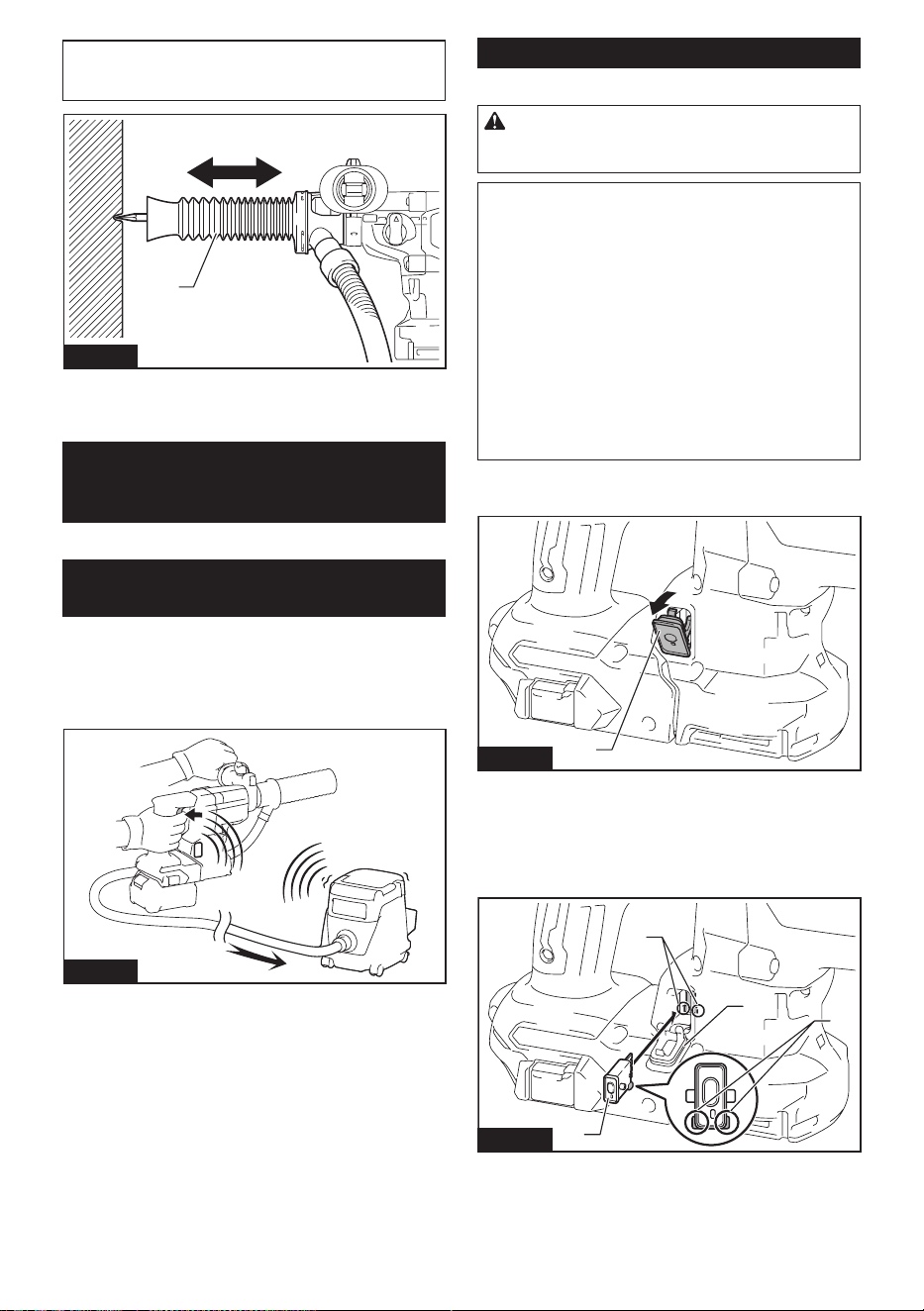
47 ESPAÑOL
NOTA:Cuandouseelfuelleparacincelado,ajuste
la longitud expandiendo y contrayendo el fuelle de
acuerdo con la longitud de la punta.
1
Fig.48
►1. Fuelle para cincelado
FUNCIÓN DE ACTIVACIÓN
INALÁMBRICA
Accesorio opcional
Lo que puede hacer con la función
de activación inalámbrica
La función de activación inalámbrica permite una ope-
ración limpia y cómoda. Si conecta a la herramienta
una aspiradora compatible, podrá hacer que ésta
funcione automáticamente al activar el interruptor de la
herramienta.
Fig.49
Para hacer uso de la función de activación inalámbrica,
tenga preparado lo siguiente:
• Una unidad inalámbrica (accesorios opcionales)
• Una aspiradora compatible con la función de
activación inalámbrica
A continuación se presenta la descripción general del
ajustedelafuncióndeactivacióninalámbrica.Consulte
cada sección para ver los procedimientos a detalle.
1. Instalación de la unidad inalámbrica
2. Registro de la herramienta para la aspiradora
3. Inicio de la función de activación inalámbrica
Instalación de la unidad inalámbrica
Accesorio opcional
PRECAUCIÓN: Coloque la herramienta sobre
una supercie plana y estable cuando vaya a
instalar la unidad inalámbrica.
AVISO: Limpie el polvo y la suciedad en la herra-
mienta antes de instalar la unidad inalámbrica.
Elpolvoolasuciedadpodríancausarunaavería
si llegan a introducirse en la ranura de la unidad
inalámbrica.
AVISO: Para evitar una avería a causa de la elec-
tricidad estática, toque un material de descarga
de electricidad estática, tal como una pieza metá-
lica de la herramienta antes de levantar la unidad
inalámbrica.
AVISO: Cuando vaya a instalar la unidad inalám-
brica, asegúrese siempre de que ésta sea inser-
tada en la dirección correcta y que la tapa esté
completamente cerrada.
1. Abra la tapa en la herramienta tal como se mues-
tra en la ilustración.
1
Fig.50
►1. Tapa
2. Inserte la unidad inalámbrica en la ranura y luego
cierre la tapa.
Cuando inserte la unidad inalámbrica, alinee las partes
salientes con las partes cóncavas en la ranura.
1
2
3
4
Fig.51
►1. Unidad inalámbrica 2. Parte saliente 3. Tapa
4. Parte cóncava
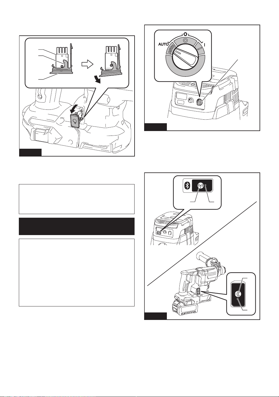
48 ESPAÑOL
Cuando extraiga la unidad inalámbrica, abra la tapa
lentamente. Los ganchos en la parte posterior de la
tapa levantarán la unidad inalámbrica mientras usted
jalahaciaarribalatapa.
1
2
3
Fig.52
►1. Unidad inalámbrica 2. Gancho 3. Tapa
Unavezextraídalaunidadinalámbrica,guárdelaenel
estuche suministrado o en un contenedor libre de elec-
tricidad estática.
AVISO: Use siempre los ganchos en la parte
posterior de la tapa cuando extraiga la unidad
inalámbrica.Silosganchosnosujetanlaunidad
inalámbrica, cierre la tapa por completo y vuelva a
abrirla lentamente.
Registro de la herramienta para la
aspiradora
NOTA: Para el registro de la herramienta, se requiere
una aspiradora Makita compatible con la función de
activación inalámbrica.
NOTA: Termine de instalar la unidad inalámbrica en
la herramienta antes de comenzar con el registro de
la herramienta.
NOTA:Duranteelregistrodelaherramienta,nojale
el gatillo interruptor ni active el interruptor de encen-
dido en la aspiradora.
NOTA: Consulte también el manual de instrucciones
de la aspiradora.
Sideseaactivarlaaspiradorajuntoconelinterruptor
de la herramienta, termine antes con el registro de la
herramienta.
1. Instalelasbateríasenlaaspiradorayenla
herramienta.
2. Ajusteelinterruptordemodoenesperaenlaaspi-
radora en “AUTO”.
1
Fig.53
►1. Interruptor de modo en espera
3. Oprima el botón de activación inalámbrica en la
aspiradora durante 3 segundos hasta que la luz indica-
dora de activación inalámbrica parpadee en verde. Y
luego oprima el botón de activación inalámbrica en la
herramienta de la misma manera.
1
2
2
1
Fig.54
►1. Botón de activación inalámbrica 2. Luz indica-
dora de activación inalámbrica
Si la aspiradora y la herramienta han sido conectadas
exitosamente, las luces indicadoras de activación ina-
lámbrica se encenderán en verde durante 2 segundos y
comenzarán a parpadear en azul.
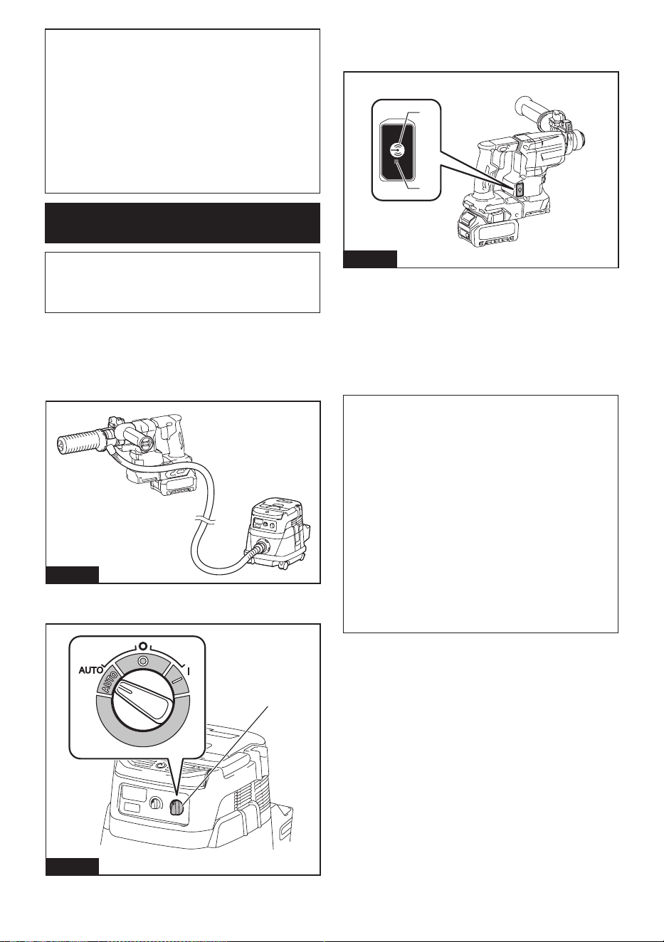
49 ESPAÑOL
NOTA: Las luces indicadoras de activación inalám-
brica terminarán parpadeando en verde después de
un lapso de 20 segundos. Oprima el botón de acti-
vación inalámbrica en la herramienta mientras la luz
indicadora de activación inalámbrica en la aspiradora
esté parpadeando. Si la luz indicadora de activación
inalámbrica no parpadea en verde, oprima el botón
de activación inalámbrica durante un lapso breve y
vuelva a mantenerlo oprimido.
NOTA: Cuando realice dos o más registros de la
herramienta para una aspiradora, termine el registro
de la herramienta de uno en uno.
Inicio de la función de activación
inalámbrica
NOTA: Termine con el registro de la herramienta para
la aspiradora antes de la activación inalámbrica.
NOTA: Consulte también el manual de instrucciones
de la aspiradora.
Después de registrar una herramienta en la aspiradora,
estaúltimaseactivaráautomáticamentejuntoconel
interruptor de la herramienta.
1. Instale la unidad inalámbrica en la herramienta.
2.
Conecte la manguera de la aspiradora a la herramienta.
Fig.55
3. Ajusteelinterruptordemodoenesperaenlaaspi-
radora en “AUTO”.
1
Fig.56
►1. Interruptor de modo en espera
4. Oprima el botón de activación inalámbrica en la
herramienta durante un lapso breve. La luz indicadora
de activación inalámbrica parpadeará en azul.
2
1
Fig.57
►1. Botón de activación inalámbrica 2. Luz indica-
dora de activación inalámbrica
5. Encienda la herramienta. Compruebe si la
aspiradora funciona mientras la herramienta está en
funcionamiento.
Para detener la activación inalámbrica de la aspira-
dora, oprima el botón de activación inalámbrica en la
herramienta.
NOTA: La luz indicadora de activación inalámbrica en
laherramientadejarádeparpadearenazulcuando
no haya operación durante 2 horas. En este caso,
ajusteelinterruptordemodoenesperaenlaaspi-
radora en “AUTO” y oprima el botón de activación
inalámbrica en la herramienta nuevamente.
NOTA: La aspiradora funcionará/detendrá con un
retraso. Existirá un desfase cuando la aspiradora
detecte la activación del interruptor de la herramienta.
NOTA: La distancia de transmisión de la unidad
inalámbrica podrá variar en función del lugar y las
circunstancias de los alrededores.
NOTA: Cuando dos o más herramientas estén regis-
tradas en una aspiradora, esta última podrá comen-
zar a funcionar incluso si usted no enciende su herra-
mienta, debido a que otro usuario está utilizando la
función de activación inalámbrica.
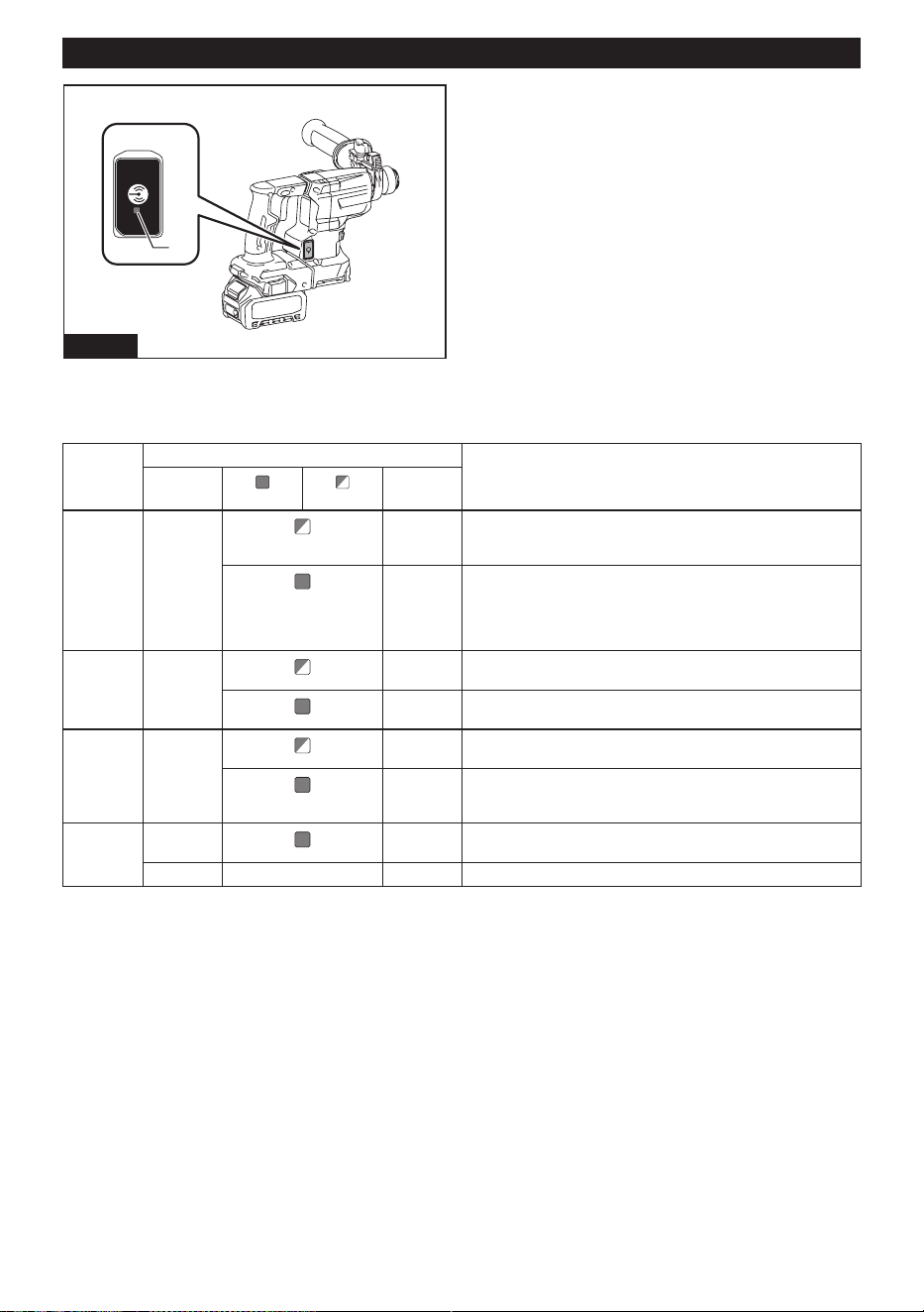
50 ESPAÑOL
Descripción del estado de la luz indicadora de activación inalámbrica
1
Fig.58
►1. Luz indicadora de activación inalámbrica
La luz indicadora de activación inalámbrica muestra el estado de la función de activación inalámbrica. Consulte la
tablaacontinuaciónparaverquésignicaelestadodelaluzindicadora.
Estado Luz indicadora de activación inalámbrica Descripción
Color
Encendida
Parpadeando
Duración
En espera Azul
2 horas La activación inalámbrica de la aspiradora está disponible. La
luz se apagará automáticamente cuando no se realice ninguna
operación durante 2 horas.
Cuando
la herra-
mienta
está fun-
cionando.
La activación inalámbrica de la aspiradora está disponible y la
herramienta está funcionando.
Registro
de la
herramienta
Verde
20
segundos
Ya se puede realizar el registro de la herramienta. Esperando el
registro por parte de la aspiradora.
2
segundos
El registro de la herramienta ha terminado. La luz indicadora de
activación inalámbrica comenzará a parpadear en azul.
Cancelación
del regis
-
tro de la
herramienta
Rojo 20
segundos
Ya se puede cancelar el registro de la herramienta. Esperando la
cancelación por parte de la aspiradora.
2
segundos
La cancelación del registro de la herramienta ha terminado. La
luz indicadora de activación inalámbrica comenzará a parpadear
en azul.
Otros Rojo
3
segundos
Laenergíaessuministradaalaunidadinalámbricaylafunción
de activación inalámbrica está arrancando.
Apagada - - La activación inalámbrica de la aspiradora se ha detenido.

51 ESPAÑOL
Cancelación del registro de la
herramienta para la aspiradora
Realice el siguiente procedimiento para cancelar el
registro de la herramienta para la aspiradora.
1.
Instalelasbateríasenlaaspiradorayenlaherramienta.
2. Ajusteelinterruptordemodoenesperaenlaaspi-
radora en “AUTO”.
1
Fig.59
►1. Interruptor de modo en espera
3. Oprima el botón de activación inalámbrica en la
aspiradora durante 6 segundos. La luz indicadora de
activación inalámbrica parpadeará en verde y luego se
pondráenrojo.Despuésdeeso,oprimaelbotónde
activación inalámbrica en la herramienta de la misma
manera.
1
2
2
1
Fig.60
►1. Botón de activación inalámbrica 2. Luz indica-
dora de activación inalámbrica
Si la cancelación se realiza exitosamente, las luces
indicadoras de activación inalámbrica se encenderán
enrojodurante2segundosycomenzaránaparpadear
en azul.
NOTA: Las luces indicadoras de activación inalám-
bricaterminaránparpadeandoenrojodespuésdeun
lapso de 20 segundos. Oprima el botón de activación
inalámbrica en la herramienta mientras la luz indi-
cadora de activación inalámbrica en la aspiradora
esté parpadeando. Si la luz indicadora de activación
inalámbricanoparpadeaenrojo,oprimaelbotón
de activación inalámbrica durante un lapso breve y
vuelva a mantenerlo oprimido.

52 ESPAÑOL
Detección y solución de problemas para la función de activación inalámbrica
Antes de solicitar alguna reparación, primero realice una inspección por su cuenta. Si detecta algún problema que
no esté explicado en el manual, no intente desensamblar la herramienta. En vez de esto, solicite la reparación a un
centro de servicio autorizado de Makita, usando siempre piezas de repuesto Makita.
Estado de la anomalía Causa probable (avería) Remedio
La luz indicadora de activación ina-
lámbrica no enciende/parpadea.
La unidad inalámbrica no está instalada
en la herramienta.
La unidad inalámbrica está instalada
incorrectamente en la herramienta.
Instale la unidad inalámbrica correctamente.
La terminal de la unidad inalámbrica y/o
la ranura está sucia.
Retire con cuidado el polvo y la suciedad en la
terminal de la unidad inalámbrica y limpie la ranura.
El botón de activación inalámbrica en la
herramienta no se ha oprimido.
Oprima el botón de activación inalámbrica en la
herramienta durante un lapso breve.
El interruptor de modo en espera en la
aspiradoranoestáajustadoen“AUTO”.
Ajusteelinterruptordemodoenesperaenla
aspiradora en “AUTO”.
Nohaysuministrodeenergía. Suministreenergíaalaherramientayala
aspiradora.
No se puede terminar/cancelar
el registro de la herramienta
exitosamente.
La unidad inalámbrica no está instalada
en la herramienta.
La unidad inalámbrica está instalada
incorrectamente en la herramienta.
Instale la unidad inalámbrica correctamente.
La terminal de la unidad inalámbrica y/o
la ranura está sucia.
Retire con cuidado el polvo y la suciedad en la
terminal de la unidad inalámbrica y limpie la ranura.
El interruptor de modo en espera en la
aspiradoranoestáajustadoen“AUTO”.
Ajusteelinterruptordemodoenesperaenla
aspiradora en “AUTO”.
Nohaysuministrodeenergía. Suministreenergíaalaherramientayala
aspiradora.
Operación incorrecta Oprima el botón de activación inalámbrica durante
un lapso breve y realice los procedimientos de
registro/cancelación de la herramienta nuevamente.
La herramienta y la aspiradora están
lejosunadelaotra(fueradelrangode
transmisión).
Acerque más la herramienta a la aspiradora. La
distancia máxima de transmisión es de aproxima-
damente 10 m, pero puede variar en función de las
circunstancias.
Antes de terminar el registro o cancela-
ción de la herramienta:
- que el interruptor de la herramienta se
encienda;o
- que el botón de la aspiradora se
encienda.
Oprima el botón de activación inalámbrica durante
un lapso breve y realice los procedimientos de
registro/cancelación de la herramienta nuevamente.
Los procedimientos de registro para
la herramienta o aspiradora no se han
terminado.
Realice los procedimientos de registro tanto para
la herramienta como para la aspiradora al mismo
tiempo.
La perturbación radioeléctrica generada
por otros aparatos que emiten ondas de
radio de alta intensidad.
Mantengalaherramientaylaaspiradoralejosde
aparatos tales como dispositivos Wi-Fi y hornos de
microondas.

53 ESPAÑOL
Estado de la anomalía Causa probable (avería) Remedio
Laaspiradoranofuncionajuntocon
el interruptor de la herramienta.
La unidad inalámbrica no está instalada
en la herramienta.
La unidad inalámbrica está instalada
incorrectamente en la herramienta.
Instale la unidad inalámbrica correctamente.
La terminal de la unidad inalámbrica y/o
la ranura está sucia.
Retire con cuidado el polvo y la suciedad en la
terminal de la unidad inalámbrica y limpie la ranura.
El botón de activación inalámbrica en la
herramienta no se ha oprimido.
Oprima el botón de activación inalámbrica durante
un lapso breve y asegúrese de que la luz indicadora
de activación inalámbrica esté parpadeando en
azul.
El interruptor de modo en espera en la
aspiradoranoestáajustadoen“AUTO”.
Ajusteelinterruptordemodoenesperaenla
aspiradora en “AUTO”.
Más de 10 herramientas están registra-
das en la aspiradora.
Vuelva a realizar el registro de la herramienta.
Si más de 10 herramientas están registradas en la
aspiradora, la herramienta registrada al principio se
cancelará automáticamente.
La aspiradora borró todos los registros
de la herramienta.
Vuelva a realizar el registro de la herramienta.
Nohaysuministrodeenergía. Suministreenergíaalaherramientayala
aspiradora.
La herramienta y la aspiradora están
lejosunadelaotra(fueradelrangode
transmisión).
Acerque más la herramienta a la aspiradora. La
distancia máxima de transmisión es de aproxima-
damente 10 m, pero puede variar en función de las
circunstancias.
La perturbación radioeléctrica generada
por otros aparatos que emiten ondas de
radio de alta intensidad.
Mantengalaherramientaylaaspiradoralejosde
aparatos tales como dispositivos Wi-Fi y hornos de
microondas.
La aspiradora funciona mien-
tras la herramienta no está en
funcionamiento.
Otros usuarios están usando la activa-
ción inalámbrica de la aspiradora con
sus herramientas.
Apague el botón de activación inalámbrica de las
demás herramientas o cancele el registro de dichas
herramientas.
MANTENIMIENTO
PRECAUCIÓN: Asegúrese siempre de que la
herramienta esté apagada y el cartucho de batería
extraído antes de intentar realizar una inspección
o mantenimiento.
AVISO: Nunca use gasolina, bencina, diluyente
(tíner), alcohol o sustancias similares. Puede que
esto ocasione grietas o descoloramiento.
Para mantener la SEGURIDAD y FIABILIDAD del pro-
ducto, las reparaciones, y cualquier otra tarea de man-
tenimientooajustedeberánserrealizadasencentros
de servicio autorizados o de fábrica Makita, empleando
siempre repuestos Makita.
ACCESORIOS
OPCIONALES
PRECAUCIÓN: Estos accesorios o aditamen-
tos están recomendados para utilizarse con su
herramienta Makita especicada en este manual.
El empleo de cualquier otro accesorio o aditamento
puede conllevar el riesgo de lesiones personales.
Utilice los accesorios o aditamentos solamente para
sunestablecido.
Si necesita cualquier ayuda para más detalles en
relación con estos accesorios, pregunte a su centro de
servicio local Makita.
• Brocas con puntas de carburo (puntas de carburo
SDS-Plus)
• Punta de corona
• Cincel de punta
• Punta de corona de diamante
• Cincel plano
• Cincel de desincrustación
• Cincel de ranurado
• Adaptador de mandril
• Portabrocas adaptador sin llave
• Grasa para puntas
• Calibrador de profundidad
• Soplador
• Contenedor de polvo
• Juego contenedor de polvo
• Fuelle (para cincelado)
• Sistema de recolección de polvo
• Conjuntodelltro
• Unidad inalámbrica
• Colgador de la herramienta
• BateríaycargadororiginalesdeMakita
NOTA:Algunosdelosartículosenlalistapueden
incluirse en el paquete de la herramienta como acce-
soriosestándar.Éstospuedenvariardepaísapaís.

54 ESPAÑOL
GARANTÍA LIMITADA DE MAKITA
Ésta Garantía no aplica para México
Consultelahojadelagarantíaanexaparaverlos
términosmásvigentesdelagarantíaaplicableaeste
producto.Encasodenodisponerdeestahojade
garantíaanexa,consultelosdetallessobrelagarantía
descritosenelsitiowebdesupaísrespectivoindicado
a continuación.
Estados Unidos de América: www.makitatools.com
Canadá: www.makita.ca
Otrospaíses:www.makita.com

55

Some dust created by power sanding, sawing, grinding, drilling, and other
construction activities contains chemicals known to the State of California
to cause cancer, birth defects or other reproductive harm. Some examples
of these chemicals are:
• lead from lead-based paints,
• crystalline silica from bricks and cement and other masonry products, and
• arsenic and chromium from chemically-treated lumber.
Your risk from these exposures varies, depending on how often you do this
type of work. To reduce your exposure to these chemicals: work in a well
ventilated area, and work with approved safety equipment, such as those
dust masks that are specially designed to filter out microscopic particles.
WARNING
< USA only >
ADVERTENCIA
Algunos polvos creados por el lijado, aserrado, esmerilado, taladrado y
otras actividades de la construcción contienen sustancias químicas
reconocidas por el Estado de California como causantes de cáncer, defectos
de nacimiento y otros peligros de reproducción. Algunos ejemplos de estos
productos químicos son:
• plomo de pinturas a base de plomo,
• sílice cristalino de ladrillos y cemento y otros productos de albañilería, y
• arsénico y cromo de maderas tratadas químicamente.
El riesgo al que se expone varía, dependiendo de la frecuencia con la que
realice este tipo de trabajo. Para reducir la exposición a estos productos
químicos: trabaje en un área bien ventilada y póngase el equipo de seguridad
indicado, tal como las máscaras contra polvo que están especialmente
diseñadas para filtrar partículas microscópicas.
< Sólo en los Estados Unidos >
Makita Corporation
3-11-8, Sumiyoshi-cho,
Anjo, Aichi 446-8502 Japan
www.makita.com
885A30-943
GRH10-1
EN, ESMX
20221220
