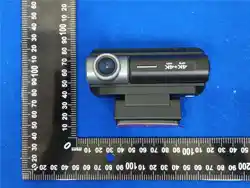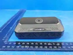
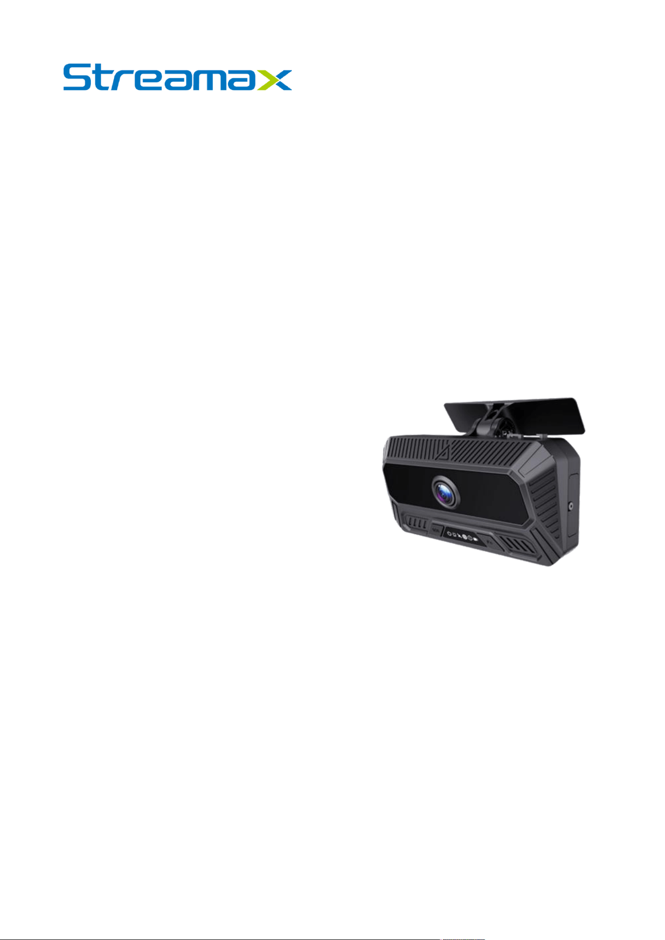
2 Channels AI Dashcam
DS100
User Manual

1
Catalog
Preface ............................................................................................................................................................. 3
About This Product Manual ......................................................................................................................... 3
Trademark Statement .................................................................................................................................. 3
Disclaimer ..................................................................................................................................................... 3
Abbreviation Explanation ............................................................................................................................... 3
Product Overview ............................................................................................................................................ 5
Product Name Description ......................................................................................................................... 5
Product Introduction .................................................................................................................................... 5
Product Features .......................................................................................................................................... 5
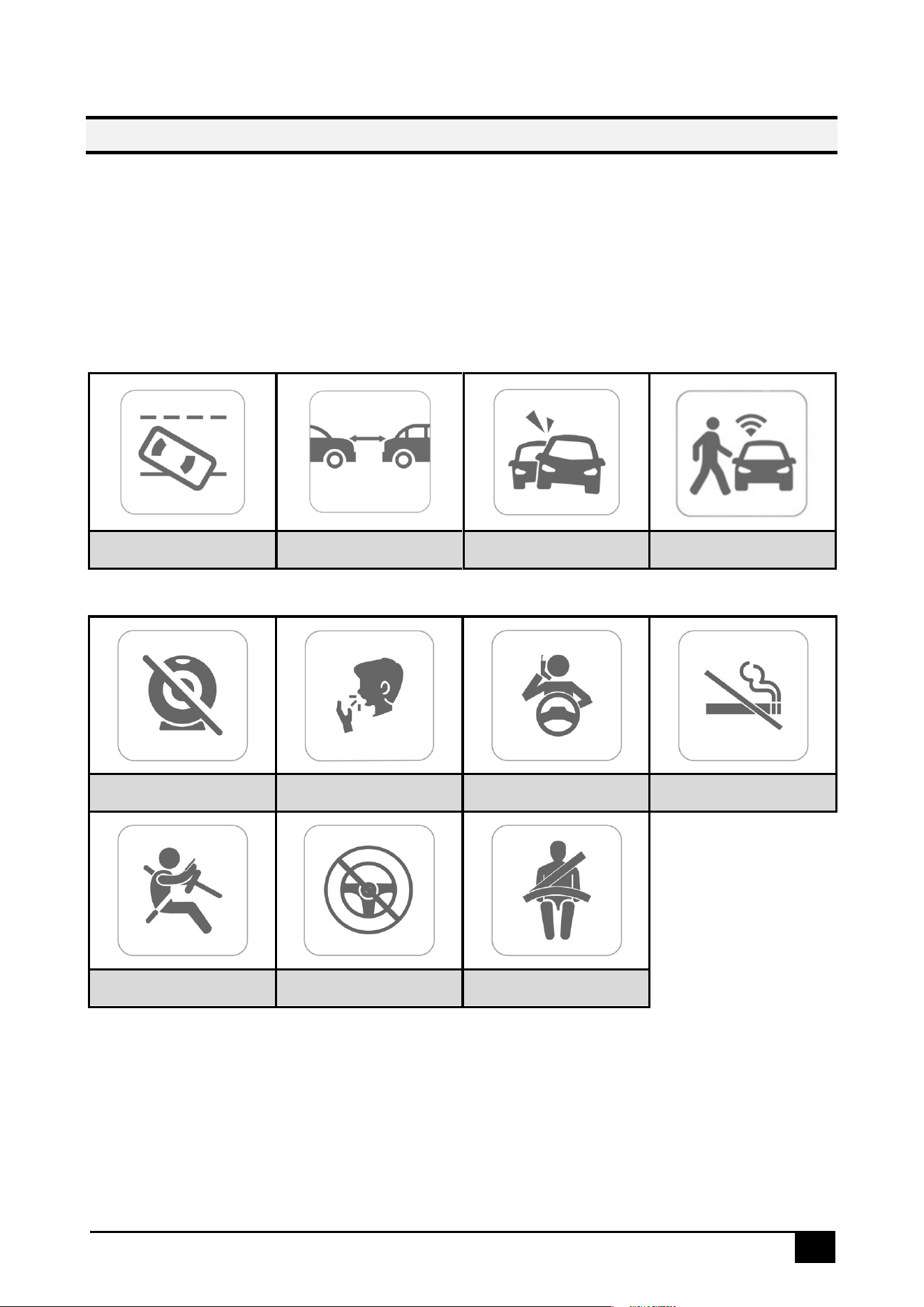
AI Features .................................................................................................................................................... 6
Product Appearance and Component Names ....................................................................................... 7
System Connection Diagram ..................................................................................................................... 9
Cables ......................................................................................................................................................... 10
Device Login .................................................................................................................................................. 12
General Information Viewing ....................................................................................................................... 13
Video Preview ................................................................................................................................................ 15
AI Calibration ................................................................................................................................................. 15
Video Playback ............................................................................................................................................. 18
Video Export ................................................................................................................................................... 20
Basic Configurations ..................................................................................................................................... 21
Registration Information ............................................................................................................................ 22
Time Setup .................................................................................................................................................. 22
Startup Setup .............................................................................................................................................. 24
User Setup ................................................................................................................................................... 27
Network Setup ............................................................................................................................................ 28
Application Setup ...................................................................................................................................... 32
Sound Setup ............................................................................................................................................... 32
Telephone Setup ........................................................................................................................................ 32

2
Video Surveillance ........................................................................................................................................ 33
Recording Setup ........................................................................................................................................ 33
Camera Setup ............................................................................................................................................ 36
Data Collection .............................................................................................................................................. 38
General Setup ............................................................................................................................................ 38
Snap Setup ................................................................................................................................................. 41
Alarm Setup .................................................................................................................................................... 43
Explanation of General Items for Alarms ............................................................................................ 43
Basic Alarms ............................................................................................................................................... 46
IO Alarm .................................................................................................................................................. 46
Speeding Alarm ..................................................................................................................................... 47
Panel Button Alarm................................................................................................................................. 47
GPS Alarm ............................................................................................................................................... 48
Idling Alarm ............................................................................................................................................ 48
Button Configuration .............................................................................................................................. 49
Sensor Alarm .......................................................................................................................................... 50
Intrusion Alarm ....................................................................................................................................... 50
Video Alarms .............................................................................................................................................. 50
Video Loss Alarm ................................................................................................................................... 50
Camera Cover Alarm ............................................................................................................................ 51
Privacy Mode ......................................................................................................................................... 52
Advanced Alarms ..................................................................................................................................... 53
Harsh Driving Alarm ............................................................................................................................... 53
Geo-Fence Alarm .................................................................................................................................. 54
Temperature and Humidity Alarm ....................................................................................................... 54
AI Alarms .................................................................................................................................................... 55
ADAS Alarms .......................................................................................................................................... 55
DMS/DSC Alarms .................................................................................................................................... 58
Calibration Parameter ........................................................................................................................... 60
Alarm Notification .................................................................................................................................. 62
Algorithm Calibration ............................................................................................................................ 62

3
Preface
About This Product Manual
This product user manual provides detailed information about the components and
functions of the DS100 product. All content, including text, images, and graphics, is the
property of Shenzhen Streamax Technology Co., Ltd. No part of this document may be
reproduced, extracted, or modified without prior written consent from the company.
Unless otherwise stated, this manual does not offer any form of warranty.
This document is intended solely for authorized users and technical support personnel.
Product images and screen content are for reference only. The actual product (including
appearance, color, and size) may differ. Please refer to the physical product for
accuracy.
Streamax Technology may update or modify the specifications from time to time to reflect
changes in product performance, functionality, or components without prior notice.
Trademark Statement
is a registered trademark of Shenzhen Streamax Technology Co., Ltd.
All other trademarks are the property of their respective owners.
Disclaimer
The product described in this document is provided “as is” without any express or
implied warranties, including but not limited to warranties of merchantability or fitness for
a particular purpose. Streamax Technology shall not be liable for any damages resulting
from the use of the product or the specifications, including but not limited to loss of
profits, data, or documentation.
When the product is connected to the Internet, Streamax Technology is not responsible
for network security risks such as cyberattacks, hacking, or virus infections. However, we
will provide technical support as necessary.
By using this product, you agree to comply with all applicable laws. Streamax
Technology is not responsible for any misuse of the product or any infringement of third-
party rights.
If there is any conflict between this specification and applicable laws, the laws shall
prevail.
Copyright © 2025 Shenzhen Streamax Technology Co., Ltd. All rights reserved.
Abbreviation Explanation
Acronym
Full Name
ADAS
Advanced Driver Assistance System
DSC
Driver Safety Cockpit
LDW
Lane Departure Warning
HMW
Headway Monitoring Warning
FCW
Forward Collision Warning
PCW
Pedestrian Collision Warning

5
Product Overview
Product Name Description
DS100 is the dual-lens model with one built-in road-facing camera and one built-in cabin-
facing camera.
Product Introduction
The DS100 is an AI-powered dashcam designed to enhance driver safety and improve
fleet management efficiency. Leveraging advanced AI technology, it actively detects
risky driving events and unsafe behaviors, providing real-time alerts to drivers to help avoid
potential hazards. The system also uploads event data to the fleet management platform
for driver training purposes. Additionally, it transmits real-time vehicle location and
operational data to the platform, offering high-quality remote communication and video
playback to streamline fleet management and boost overall efficiency.
Product Features
⚫ Built-in forward high-definition road camera supporting 1080P video recording.
⚫ Built-in in-cabin ultra-wide-angle lens supporting up to 1080P video recording.
⚫ Supports H.264/H.265 encoding.
⚫ Supports up to 1*1TB external Micro SD card storage, and Built-in 1*eMMC storage(Up
to 256GB)allowing simultaneous storage of both main and sub-streams.
⚫ Built-in 4G communication module (eSIM supported), and GNSS positioning module.
⚫ Audio and video data supports AES-256 encryption, data transmission uses encrypted
TLS 1.3 protocol.
⚫ Supports 2-channel input,1-channel output, 1-channel CAN and 1-channel RS232.
⚫ Compact design, does not obstruct the driver's view on both large and small vehicles.
⚫ Supports OBD power supply, convenient and quick installation.
⚫ Built-in ADAS features (3.85 mm road-facing lens), support lane departure warning,
forward collision warning, pedestrian collision warning and headway monitoring
warning.
⚫ Built-in DSC function, supports detection of poor driving behavior.
⚫ Supports echo suppression algorithm to improve two-way intercom quality
⚫ Supports sleep mode and remote wake-up.
⚫ Built-in 6-axis gravity sensor, supports detection of rapid acceleration, rapid
deceleration, sharp turns, and collisions.
⚫ Built-in WIFI/Bluetooth, supports Bluetooth IoT peripherals such as fuel level sensor, tire
pressure sensor, speed sensor, etc.
⚫ Supports 2 sets of button functions: one set of emergency alarm buttons and one set
of function buttons.
6
AI Features
The DS100 uses advanced video analysis technology and machine vision to automatically
detect road hazards and unsafe driver behaviors. The system continuously monitors and
triggers both visual and auditory alerts to remind the driver to pay attention to safety.
Additionally, relevant alarm footage is automatically uploaded to the cloud for real-time
monitoring and review.
➢ ADAS Features
LDW
HMW
FCW
PCW
➢ DSC Features
Lens Covering
Yawning
Phone
Smoking
Distraction
No Driver
Seat belt
7
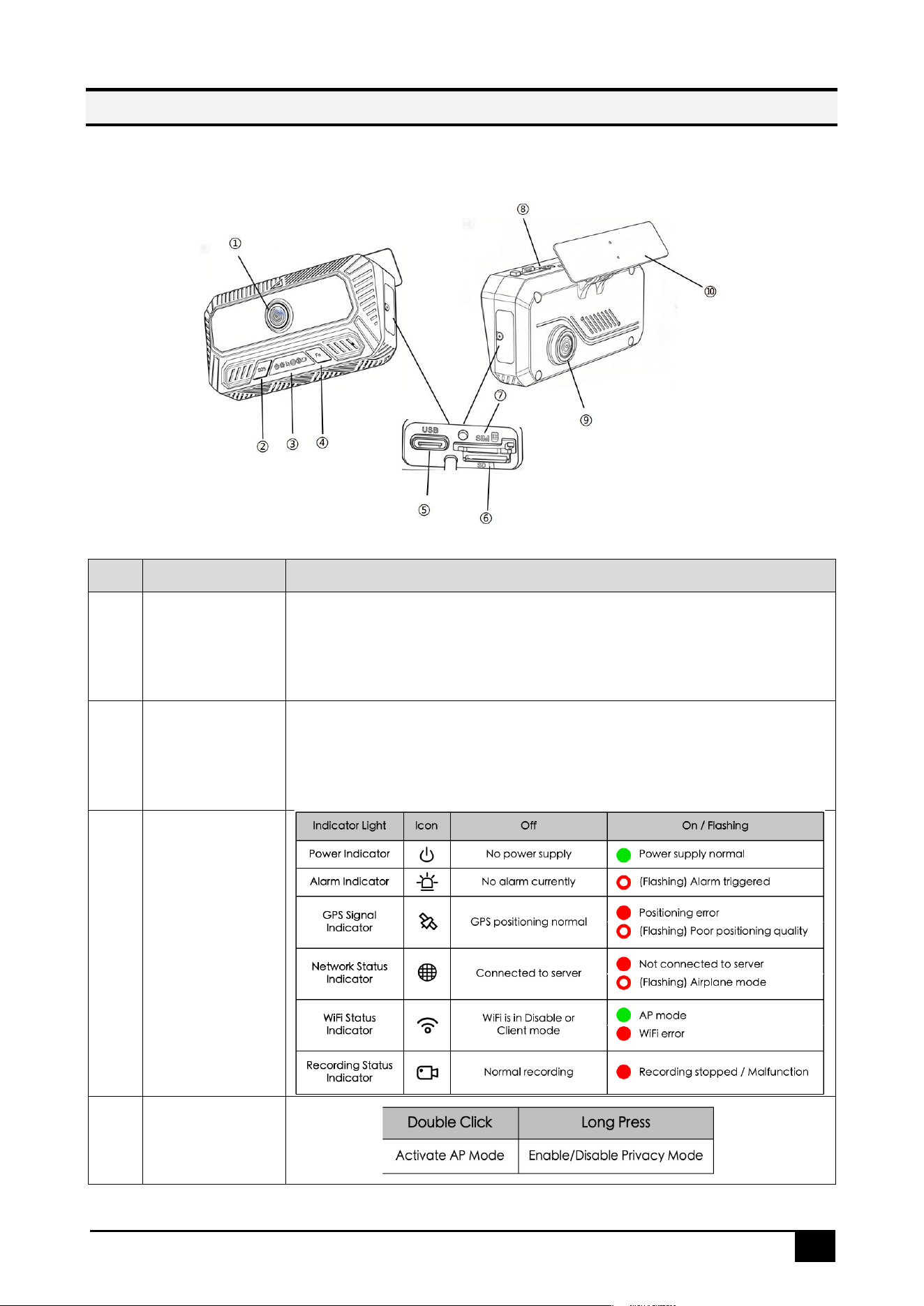
Product Appearance and Component Names
➢ DS100 Front & Side View
No.
Name
Description
1
Cabin-facing
Camera
A rear-mounted, ultra-wide-angle cockpit camera that supports
up to 1080P HD recording. The main unit integrates a DSC
algorithm capable of detecting various driver behaviors.
2
Emergency
Alarm Button
Click to trigger an emergency alarm.
3
Status Indicator
Light
4
Function Button

8
5
USB Type C
Port
Primarily used for maintenance purposes such as firmware
updates, device configuration, export video or troubleshooting.
6
Micro SD Card
Slot
Supports single Micro SD card storage (up to 1TB), allowing
simultaneous recording of both the primary and secondary
video streams, thereby offering flexible storage options for data
recording.
7
SIM Card Slot
Features an integrated 4G communication module, enabling
real-time data upload and remote access via the 4G network.
8
Cable fixing
clip
Insert the included power cable into this port to connect to the
vehicle's power supply.
9
Road-facing
Camera
Equipped with a wide-angle front lens that supports up to 1080P
HD recording. The main unit includes an ADAS algorithm
capable of detecting road conditions.
10
Installation
Bracket
A mounting bracket designed to secure the camera installation.
It is equipped with 3M adhesive for firm attachment to glass, is
compatible with various vehicle cockpit interiors, and is easy to
install. The bracket’s adjustable angle ensures an optimal field of
view.
9
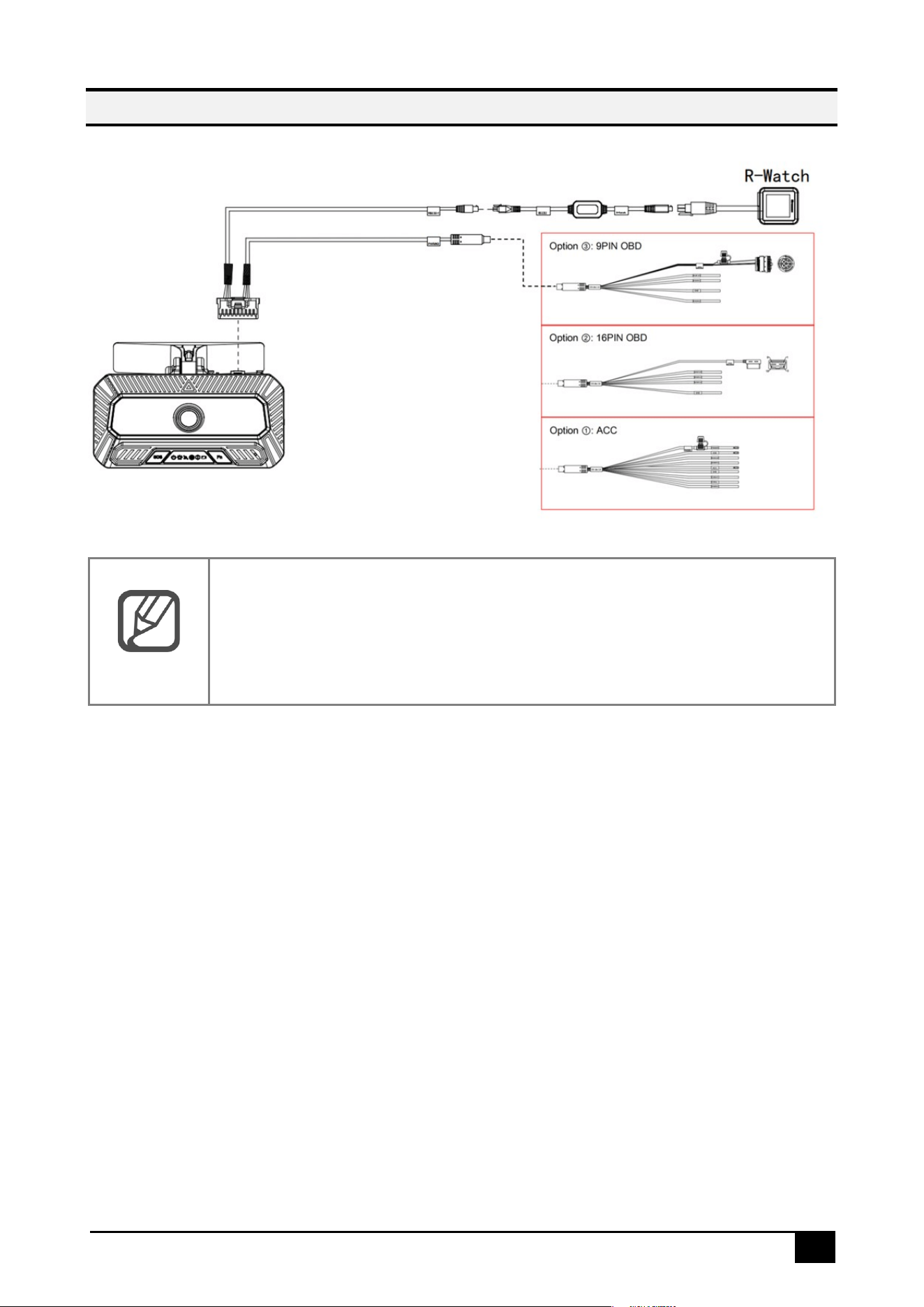
System Connection Diagram
Note
⚫ R-Watch: A peripheral device used for driver safety alerts through visual
and audible warnings.
10
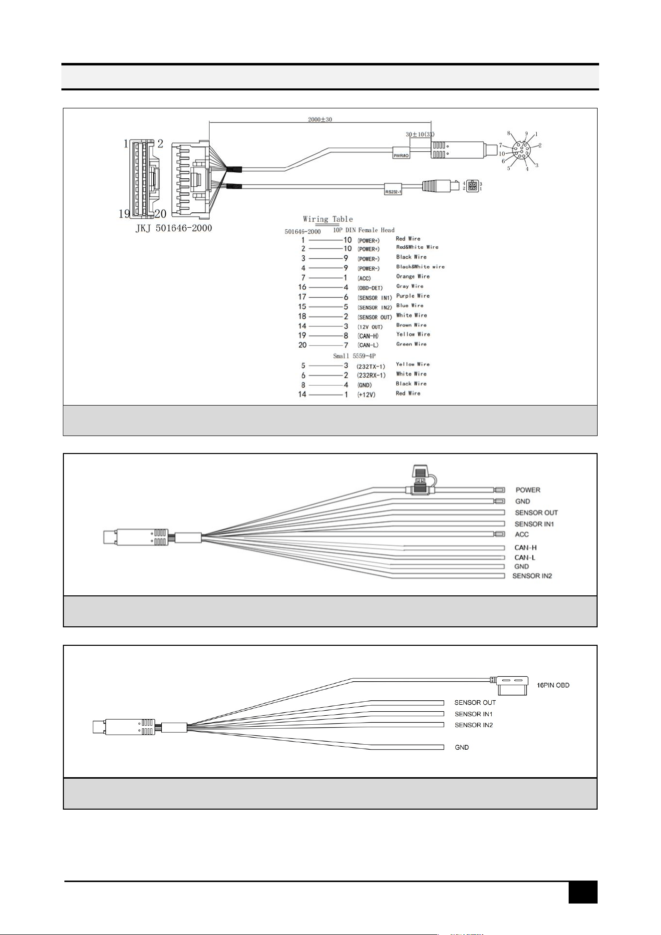
Cables
Power Cable
ACC Power Cable
16PIN OBD Power Cable — Optional
11
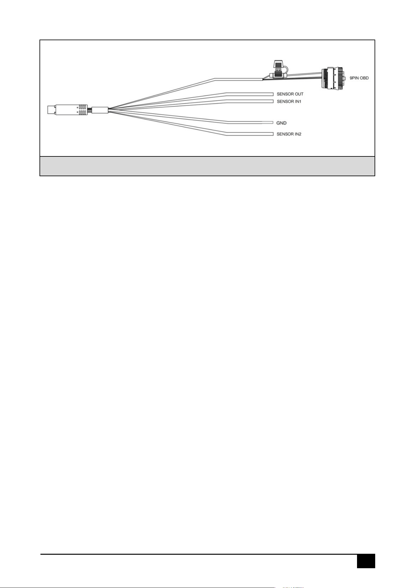
9PIN OBD Power Cable
12
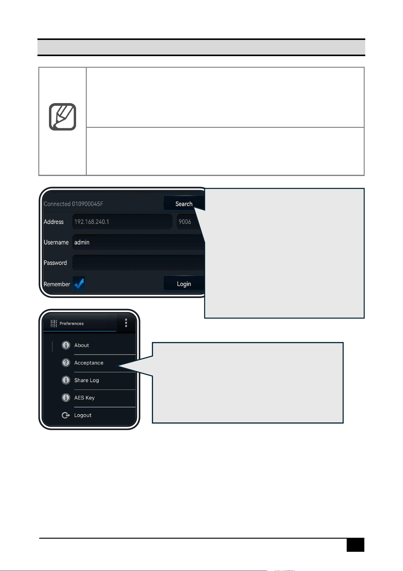
Device Login
Note
AP Mode: To connect to the device's Wi-Fi hotspot, the device must be in
AP mode. The device will be in AP mode for the first 3 minutes after startup.
You can also manually switch to AP mode at any time by double-clicking the
function button on the device.
Mobile App Installation:
⚫ For Android users, search for Veyes in Google Play to download
⚫ For iPhone users, search for Veyes in the App Store to download
1. Click [Search] to enter the Wi-Fi
settings. Select the corresponding
device hotspot and connect. The initial
hotspot name will be the device’s
Serial Number, which can be found on
the label on the device
2. Enter the username and password,
The default credentials are:
admin/admin
3. Click [Log in]
to access the operation
interface
1. Click the top-right corner
to view information
such as the APP version and other details
2. [Acceptance]: Acceptance Mode. This mode is
used for testing or accepting the device in a
static environment. It triggers AI alerts based on
a preset vehicle speed
13
General Information Viewing
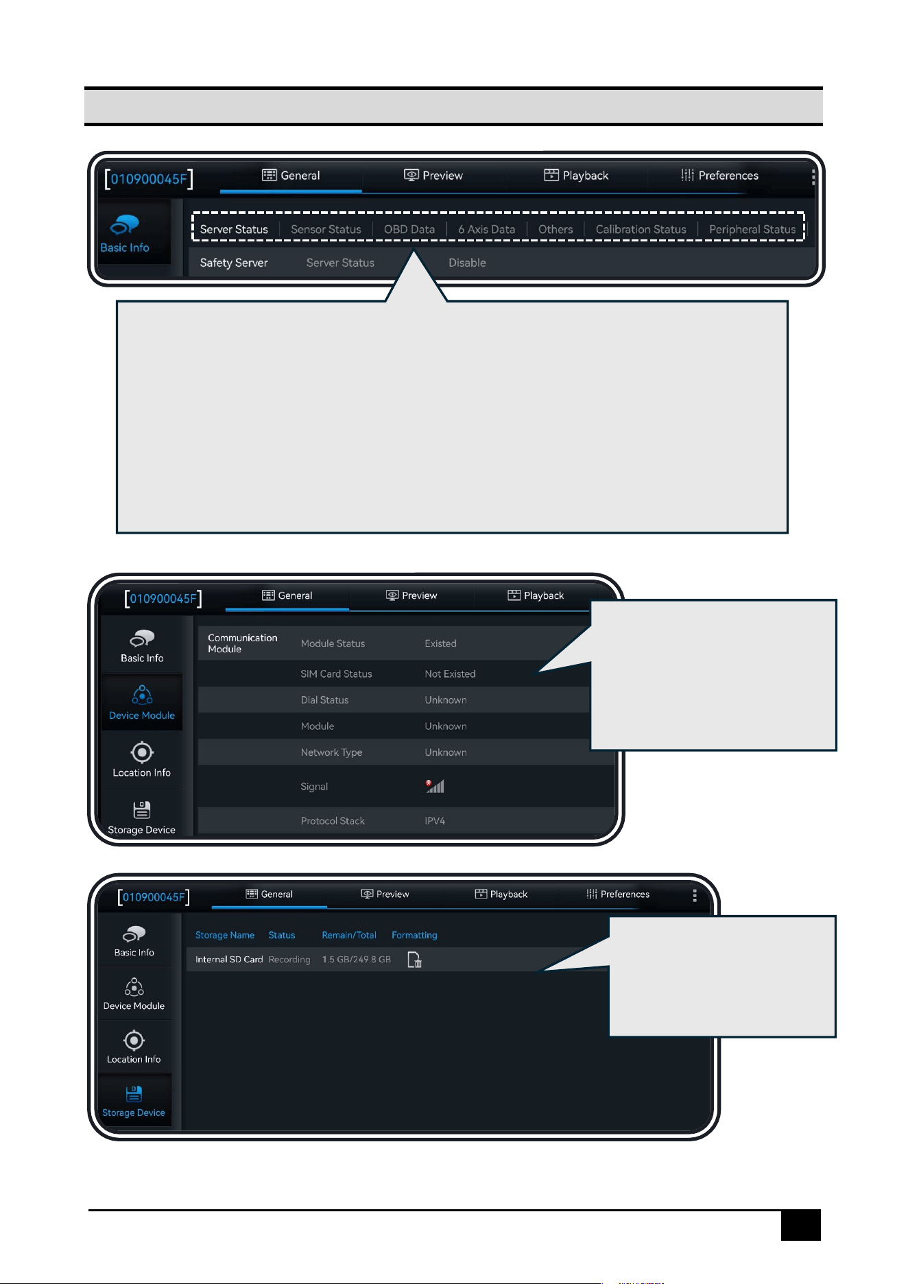
Click [General] → [Basic Info] to view the device’s basic information:
1. [Server Status]:View the server connection status
2. [Sensor Status]:View the high/low voltage status and usage of the I/O
3. [OBD Data]:View the vehicle data read by the device from the OBD port
4. [6 Axis Data]:View the G-Sensor's six-axis data
5. [Others]:View the ACC status, pulse status, and device status
6. [Calibration Status]:View the AI algorithm calibration status
7. [Peripheral Status]:View all peripheral device status
Click [General] → [Device
Module]: View information
about the device's Wi-Fi, 3/4G,
eSIM, Positioning, and
Bluetooth modules
Click [General] → [Storage
Device]: View the storage
status and perform
formatting operations
14
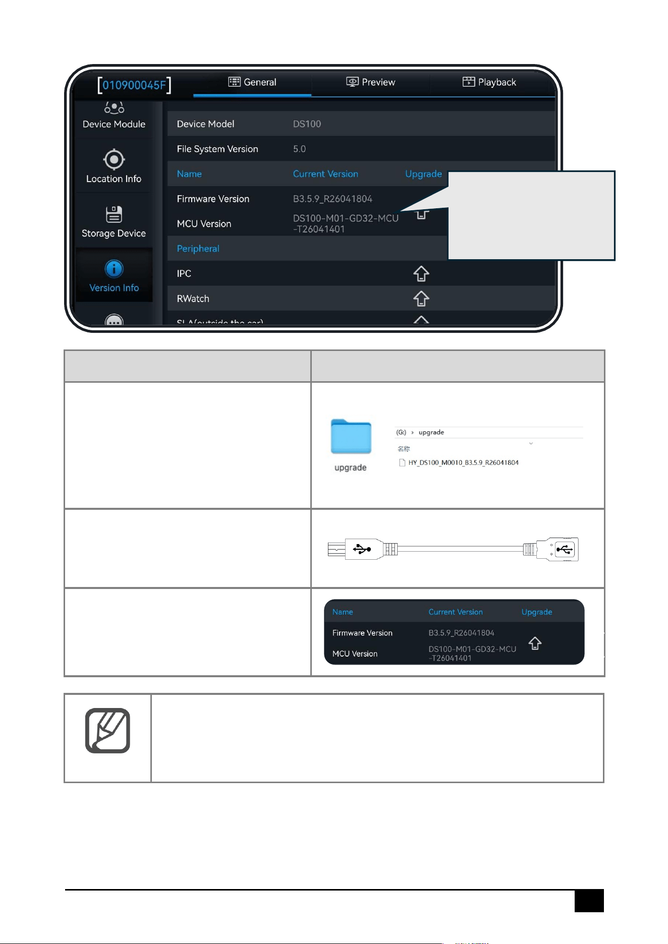
Upgrade Steps
Image Explanation
1. Prepare a USB flash drive and create
a folder named upgrade in the root
directory. Then place the upgrade
package into the folder
2. Connect the USB flash drive to the
device via the maintenance cable
(The USB flash drive with a Type-C
interface does not require this
cable)
3. Click Upgrade
Note
The above steps outline the local upgrade process via Veyes. The device
also supports online upgrades through the FT platform. For details, please
refer to the platform documentation or consult relevant personnel.
Click [General] → [Version
Info]: View or upgrade the
software version
15
Video Preview
AI Calibration
Click [Preferences] – [Alarm] – [AI APP] – [Calibration Parameters]: DS100 supports ADAS
and DMS auto-calibration. Enter parameter information as instructed.
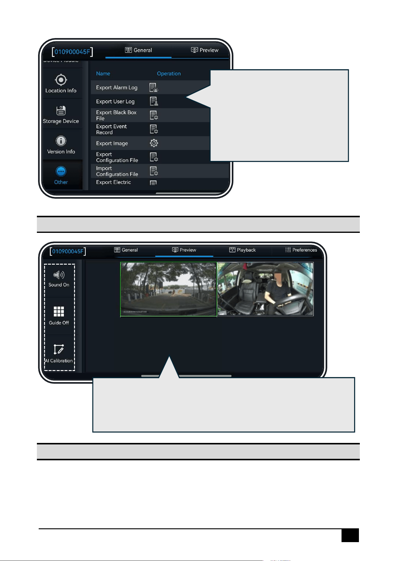
Click [General] → [Other]: Supports
operations such as importing/exporting
data and configuration parameters,
restoring factory settings, and restarting
the device
*Import/Export operations require an
external USB drive
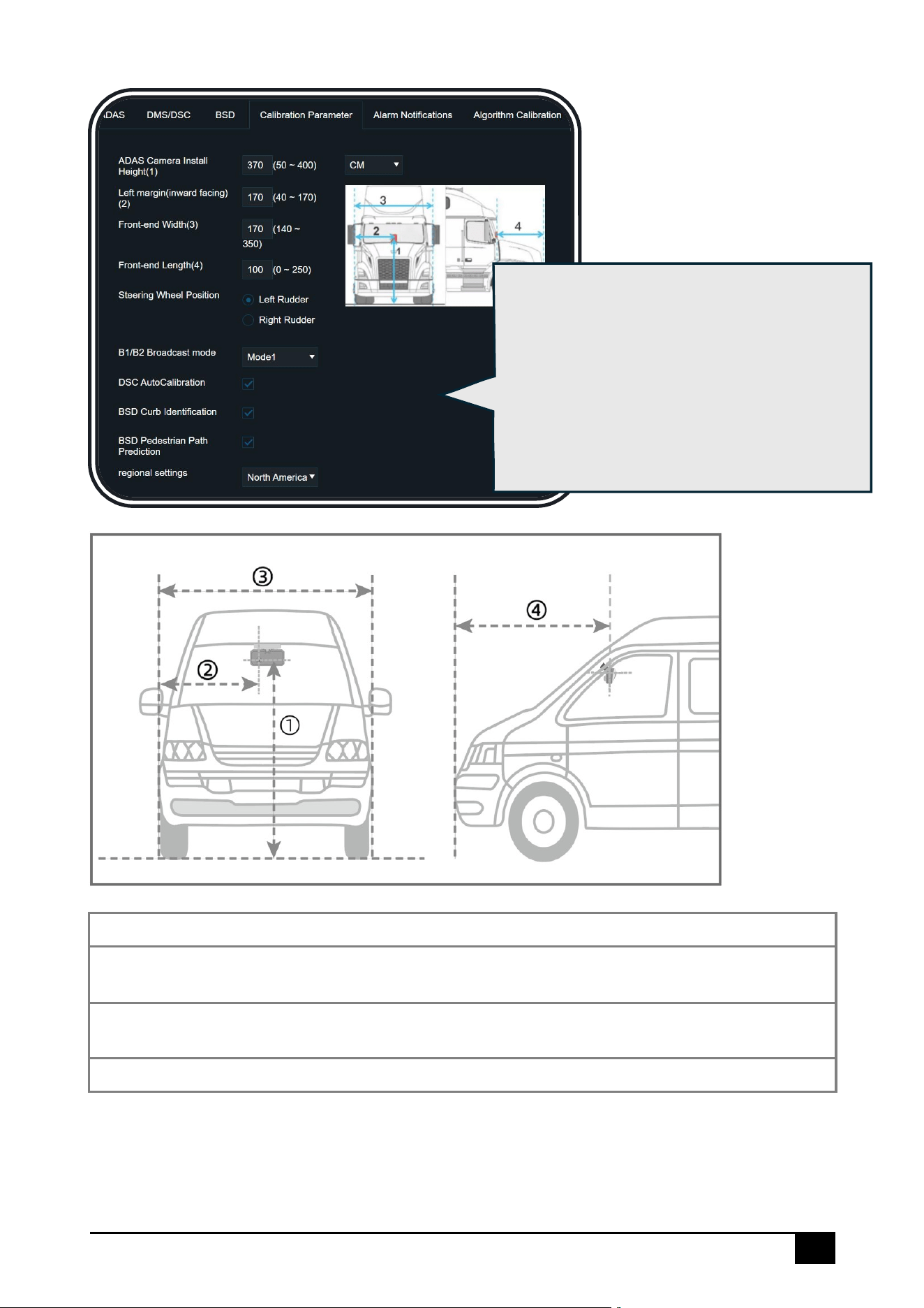
Click [Preview]: View the real-time feed of each channel. Double-click to
enlarge the preview. If no camera is connected or the camera channel is
damaged, "Video Loss" and “No Device” will be displayed. It supports the
operation of turning sound on/off, turning grid on/off, and AI calibration
16
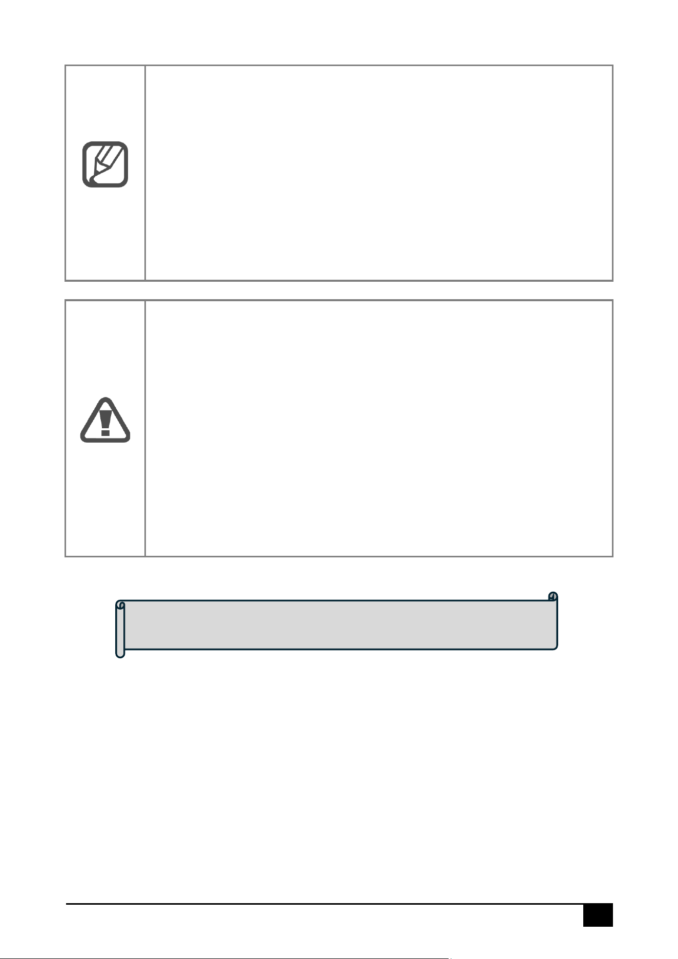
① Vertical distance from the camera to the ground
② Horizontal distance from the camera to the outer side of the vehicle’s left front wheel
③ Horizontal distance between the outer sides of the vehicle’s front wheels
④ Distance from the camera to the front of the vehicle
In this interface, you can configure the
installation position of the dashcam. Accurate
position information improves the accuracy of
the ADAS algorithm. Additionally, you can
configure the steering wheel position (left-
hand or right-hand drive), region (to enhance
the recognition accuracy of stop signs and
speed limit signs), and whether to enable DSC
automatic calibration
17
Note
Auto-Calibration Instructions
After initial installation, angle adjustment, and parameter input, DS100 will
Auto-Calibrate if these conditions are met:
1. Speed >15 km/h, following a vehicle 10–40 m ahead in the same lane
for >5 sec.
2. Speed >50 km/h on a road with clear, long lane markings, staying
centered in the lane (both lane lines clearly visible) for >5 sec.
Auto-Calibration runs in real time once speed, distance, and road
conditions are satisfied.
Warning
Auto-Calibration Failure Causes:
⚫ Installation issue: Excessive vertical angle or misalignment of the
device installation.
⚫ Incorrect calibration parameters: Improper parameter input may
trigger false alarms.
⚫ Unmet conditions for auto-calibration: Required speed, distance to
preceding vehicle, or road conditions were not satisfied.
⚫ No speed signal: No speed input source (GPS, pulse, etc.) was
detected during operation.
Please troubleshoot based on the above causes. If unresolved, please
contact Streamax technical support for evaluation.
At this point, ADAS/DMS calibration is complete
18
Video Playback
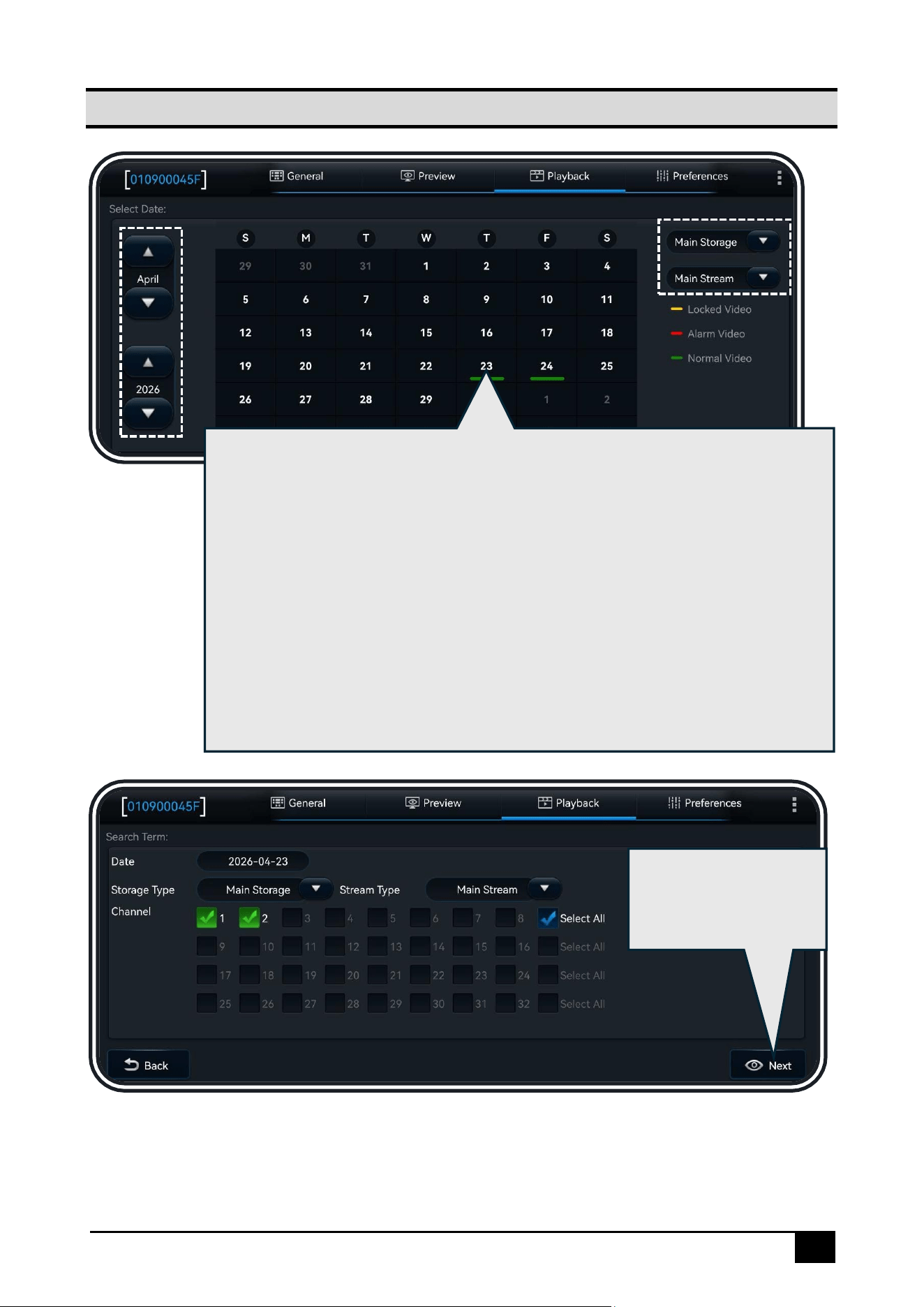
1. Click [Playback], and you can select the year and date
on the left side of
the screen. In the calendar, the color bar under each date indicates that
there is video recorded on that day, with different colors representing
different types of videos
2. On the right side of the screen, you can select the Main/Sub Storage (The
DS100 supports one Micro SD card and built-in one eMMC card). In the
storage, you can choose between Main/Sub stream:
⚫ Main Stream: HD quality, primarily used for video recording storage,
providing video evidence
⚫ Sub Stream: SD quality, mainly used for remote preview and can also
be used for long-duration video storage
Select the channel you
want to playback, then
click [Next]
19
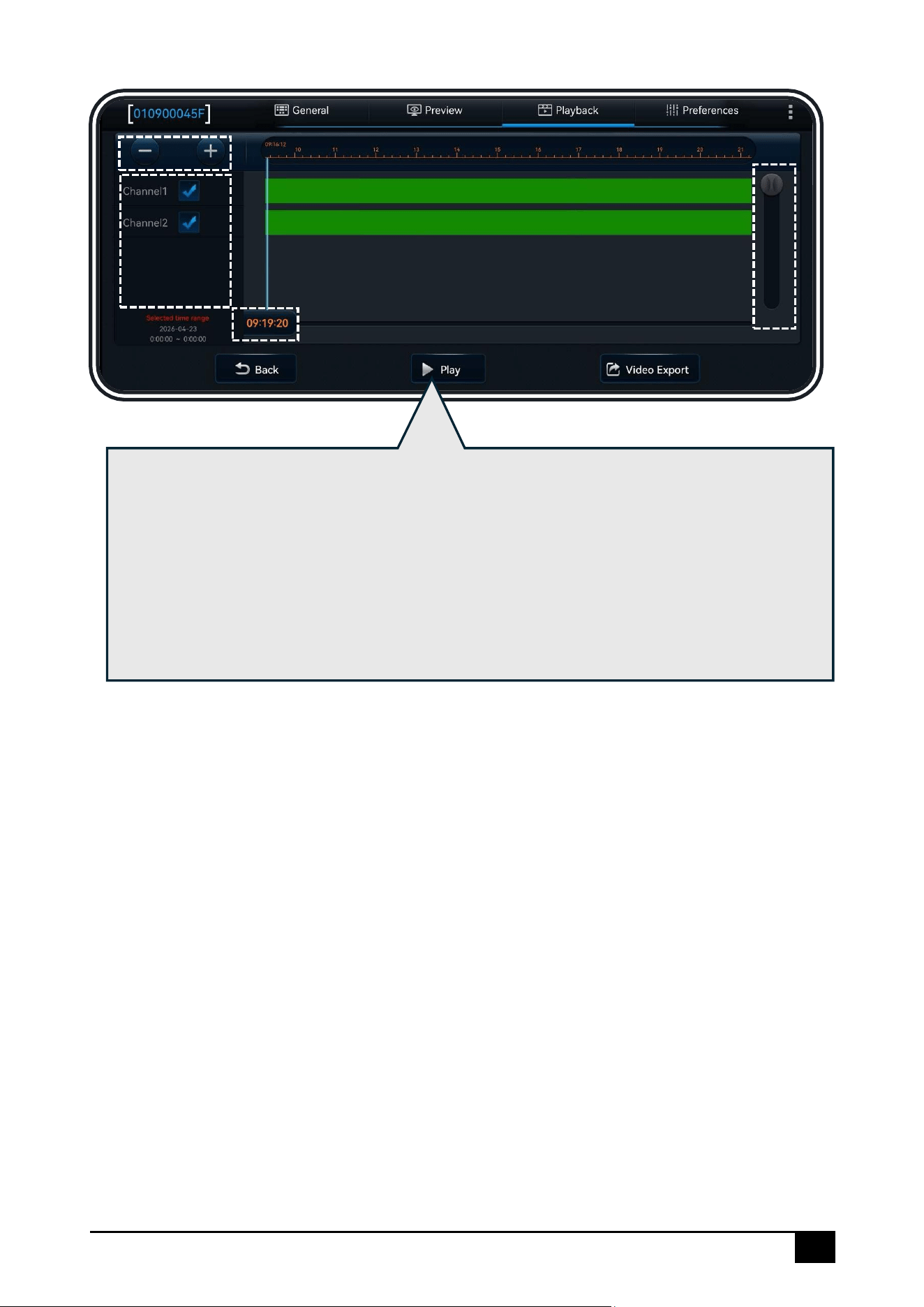
1. The top section shows the timeline. You can zoom in/out the timeline by clicking the
button in the top-left corner
2. Check the box for the channel you want to playback
3. The color bar on each channel represents the type of video recorded during a specific
period
4. Drag the timeline to start the playback from a specific time point
5. Drag the channel axis on the far right to view the corresponding channels for CH1 to
CH2
6. Click [Play] to start the playback
20
Video Export
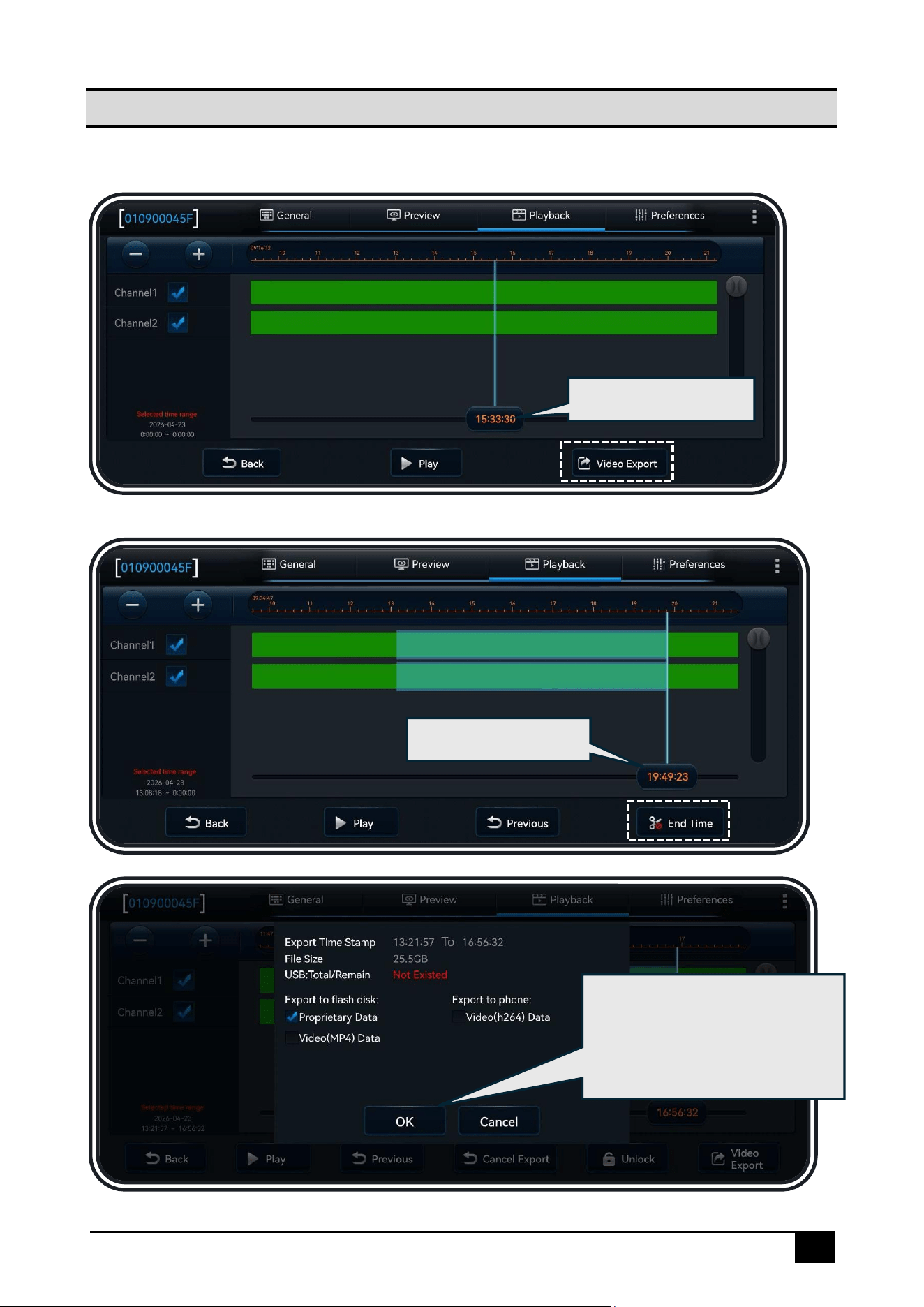
Refer to the last page of the previous section's diagram, then click [Video Export]:
Select the start time
Select the end time
Choose the export data format,
then click [OK] to export the
video (the device must be
connected to a USB flash drive)
21
Warning
Exporting in MP4 format allows playback on regular media players.
Exporting in H264 format requires a dedicated player (CEIBA2 client). The
H264 format contains more raw data, which is helpful for troubleshooting. If
you require after-sales support, please choose to export in H264 format
Basic Configurations
Note
In all configuration parameter interfaces, after modifying the parameters,
click the [Save] button at the bottom of the screen to save the changes.
Click [Default] to restore all the default parameters on that interface
Warning
Due to the wide range of features of this product, this user manual only
covers the most used settings. If you have any other questions, please feel
free to contact us
22
Registration Information
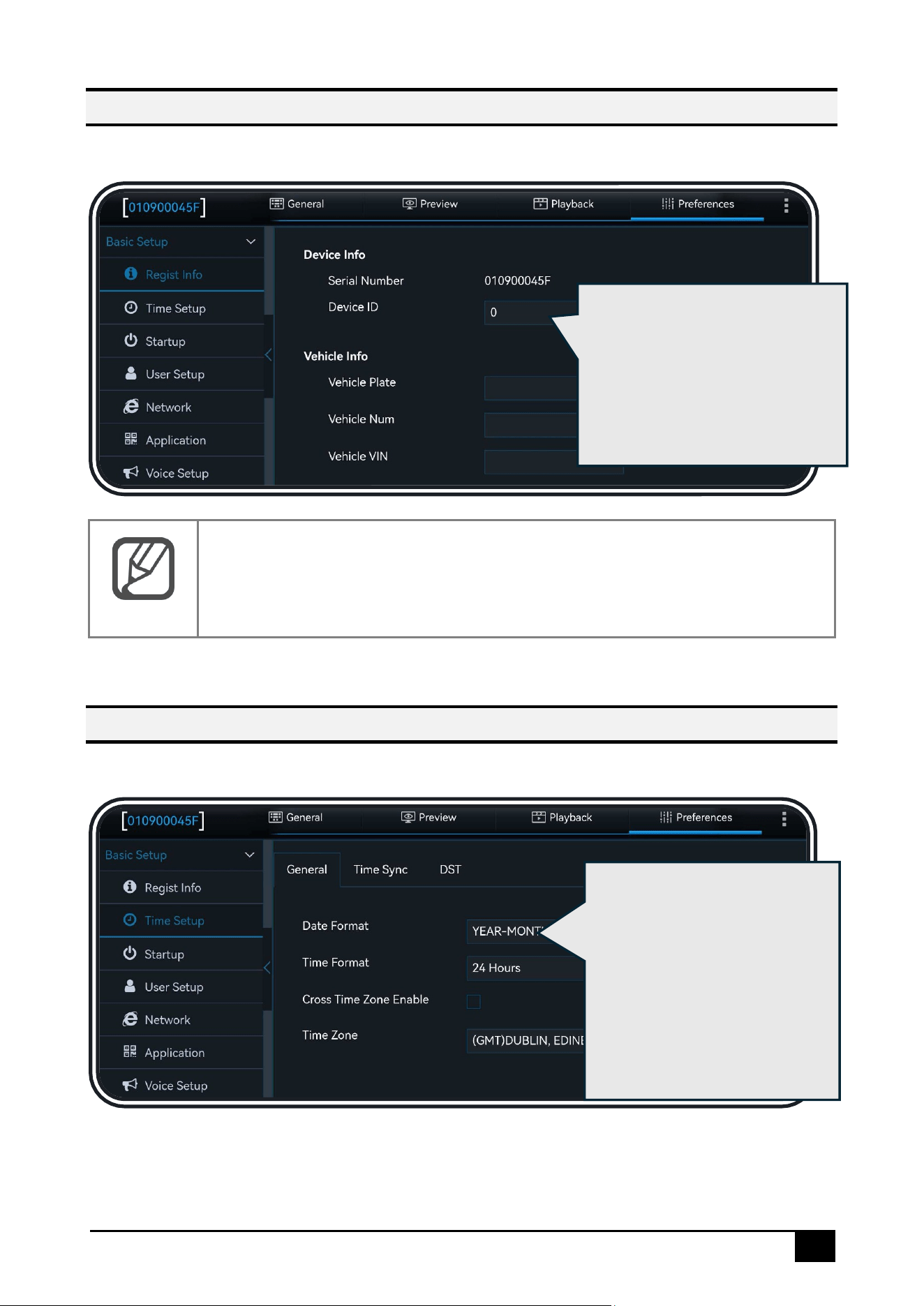
Click [Preferences] – [Basic Setup] – [Regist Info]:
Note
Once you enter the license plate number, the Wi-Fi hotspot name will be
renamed to the license plate number. You will then need to reconnect to
the Wi-Fi and log in to Veyes again
Time Setup
Click [Preferences] – [Basic Setup] – [Time Setup]:
In this interface, you can fill in the
basic information: Device ID,
License Plate Number, Vehicle
Number, Vehicle VIN, Driver's
Employee ID, and Name
Click [General] to set the time
display format and the
device's time zone. Enabling
[Cross Time Zone Enable] will
make the time zone
parameter unmodifiable, and
an option to set the local time
zone will be added
23
Note
Cross Time Zone Enable: When the vehicle and platform are in different
time zones, enable this option to maintain proper communication between
the device and the platform. Once enabled, the [Time Zone] setting
becomes unmodifiable, and both the platform and the device will use the
UTC (Zero) time zone for data exchange. A [Local Time Zone] setting is
added to be used for overlaying time zones on the video recordings
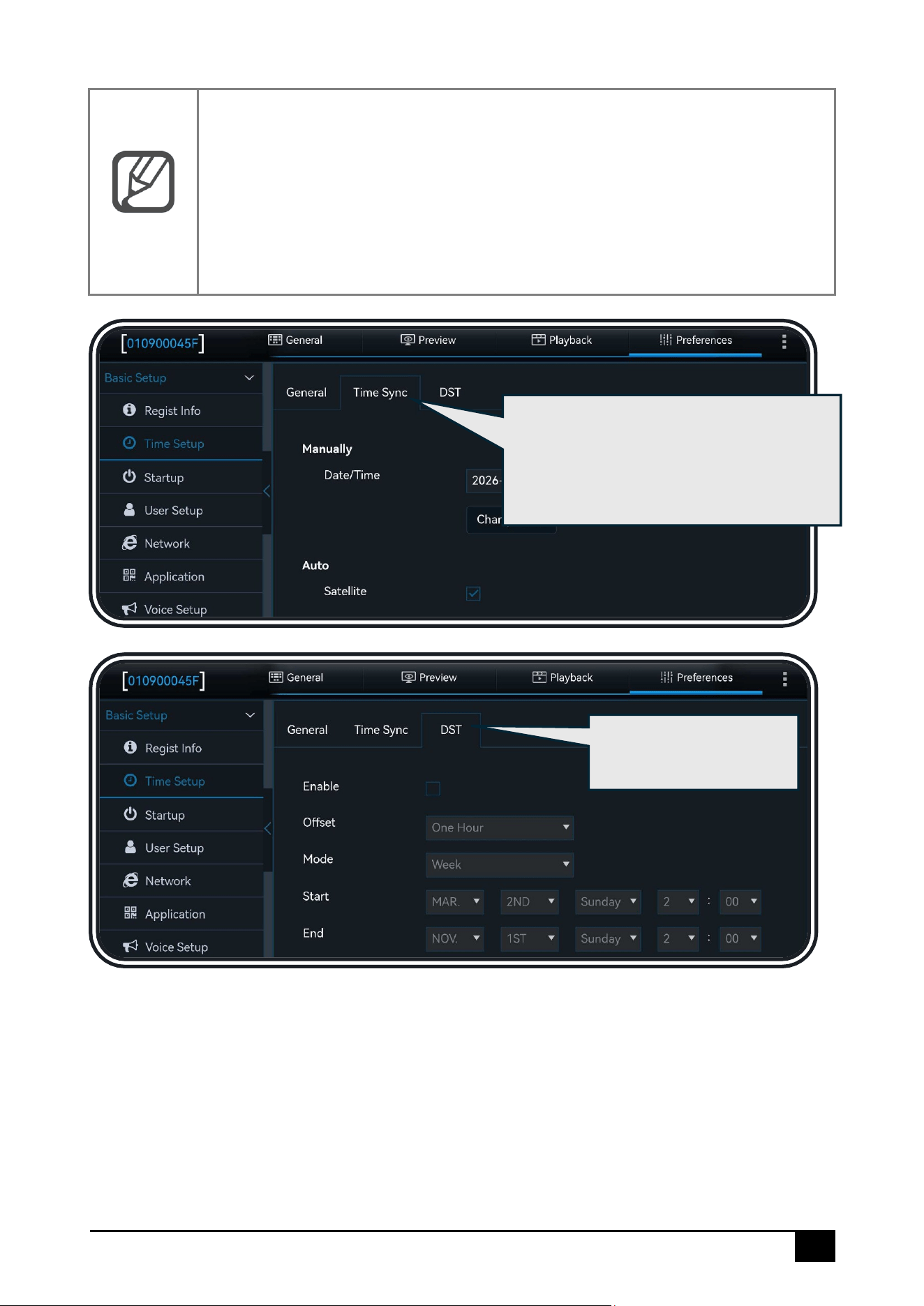
Click [Time Sync] to manually or
automatically set the date and time.
The automatic setting option allows you
to choose the time synchronization
method
Click [DST] to set Daylight
Saving Time
24
Startup Setup
Click [Preferences] – [Basic Setup] – [Startup]:
Note
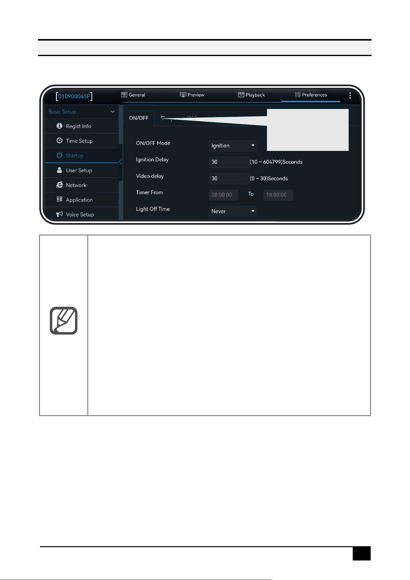
1. [ON/OFF Mode]: Select the [Ignition] for power on/off (that is, start the
device by turning on the car key).
2. [Ignition Delay]: Set the time for delayed shutdown after the car key is
turned off. It can be set from 0 to 86399 seconds, with the default being
300 seconds.
3. [Video Delay]: Set the time for delayed video recording after ignition
shutdown. The video recording delay time ≤ the ignition shutdown delay
time.
4. [Timer From]: Select the period for timed power-on.
5. [Light Off Time]: When an external display screen is connected, you can
configure the time for the screen backlight to turn off.
6. [Reboot Delay]: When enabled, the device will automatically restart
once after the set time, and then start the shutdown countdown again.
Click [ON/OFF] to set
the device status
after ACC OFF
25
Note
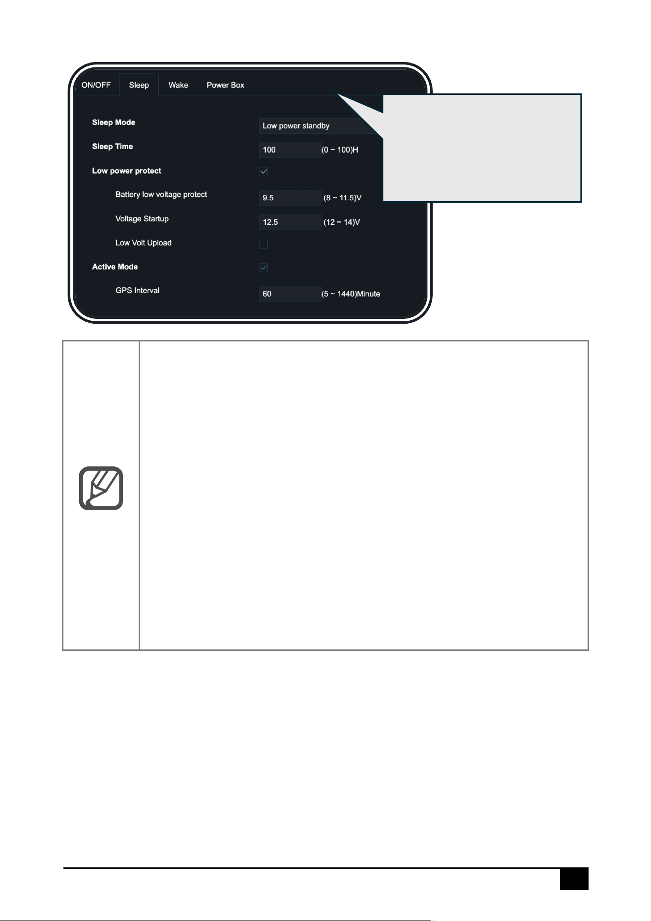
1. No consumption standby: Zero power standby (i.e., off). The device will
not be awakened, and it cannot interact with the platform
2. Low power standby: The device is in low power standby mode, where it
can be awakened and interact with the platform
3. [Sleep Time]: This parameter indicates the duration the device stays in
low power standby mode without being awakened or started. After this
time, the device will enter zero power standby
4. [Battery low voltage protect]: When the battery voltage falls below the
set value, the device will enter low power standby mode when ACC ON
and zero power standby mode when ACC OFF
5. [Voltage Startup]: In low power standby mode, when the battery voltage
exceeds the set value, the device will return to normal startup mode
6. [Low Volt Upload]: When enabled, the device will report to the platform
when the low voltage protection is triggered
Click [Sleep] to select the device's
sleep mode. You can modify the
sleep time, low voltage protection
parameters, and the GPS reporting
interval during sleep
26
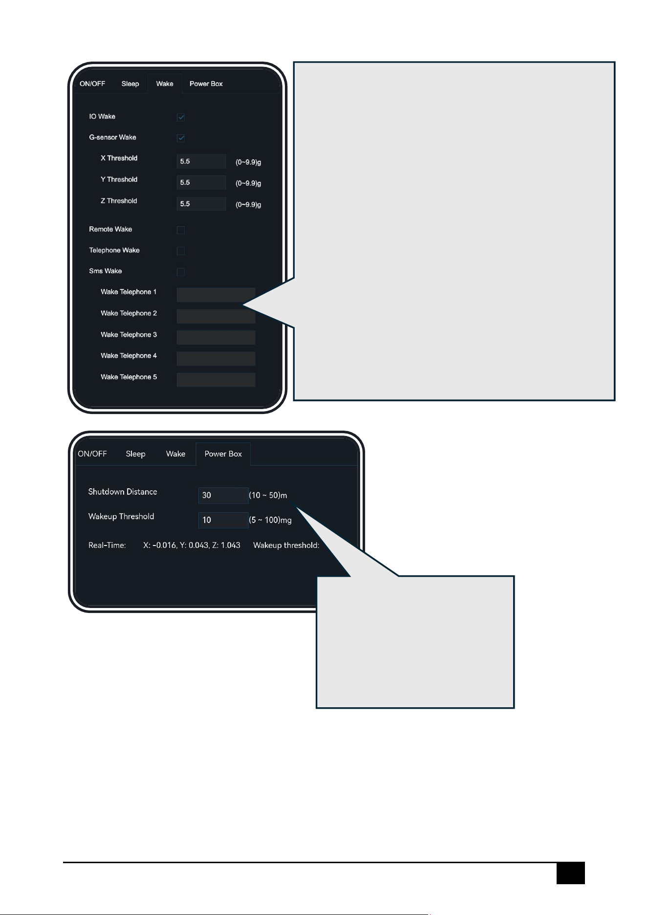
Click [Wake] to select the device's wake-up method:
⚫ IO Wake: The device will be awakened after an IO
alarm is triggered
⚫ G-Sensor Wake: The device will be awakened when
its motion exceeds the threshold
⚫ Remote Wake: The device will be remotely awakened
by issuing a command from the platform
⚫ Call Wake: The device will be awakened by a phone
call, requiring a pre-configured phone number that
supports wake-up
⚫ SMS Wake: The device will be awakened by sending
a text message to the device, with the message
content as "WAKEUP". The phone number that
supports wake-up must be pre-configured
* The Call Wake and SMS Wake functions require the SIM
card in the device to support SMS and voice call services
Click [Power Box] to select waking
up via the power box. You can also
modify the threshold for triggering
wake-up of the power box. This
feature requires connection to a
power box
27
User Setup
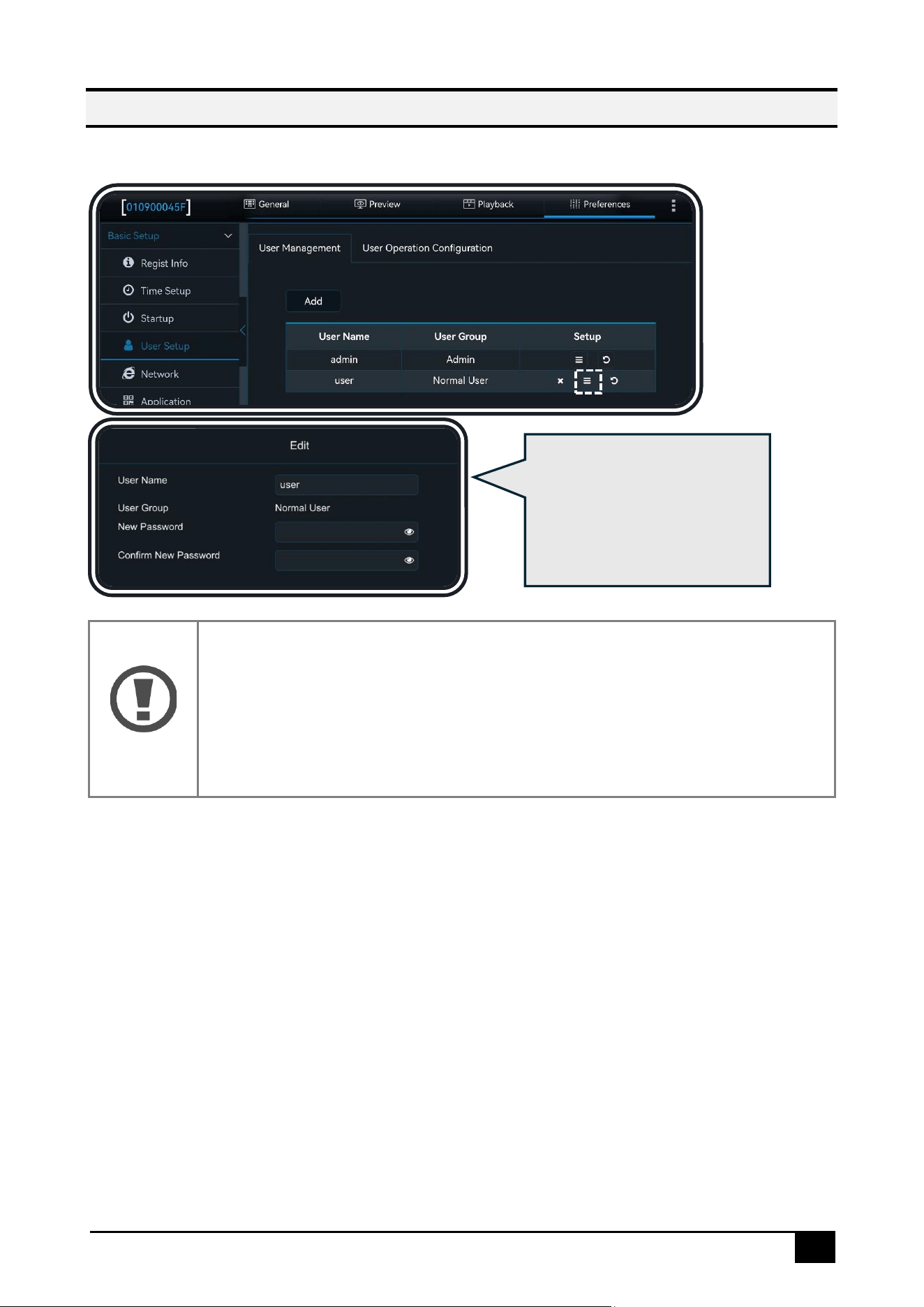
Click [Preferences] – [Basic Setup] – [User Setup]:
Warning
1. Admin: There is only one admin account, which has the permission to
add/delete normal users and set parameters. A maximum of two normal
users can be added
2. Normal User: A default normal user account is created, which only has
permission to view settings
In this interface, you can
configure the login user
information, including
modifying the username and
password.
28
Network Setup
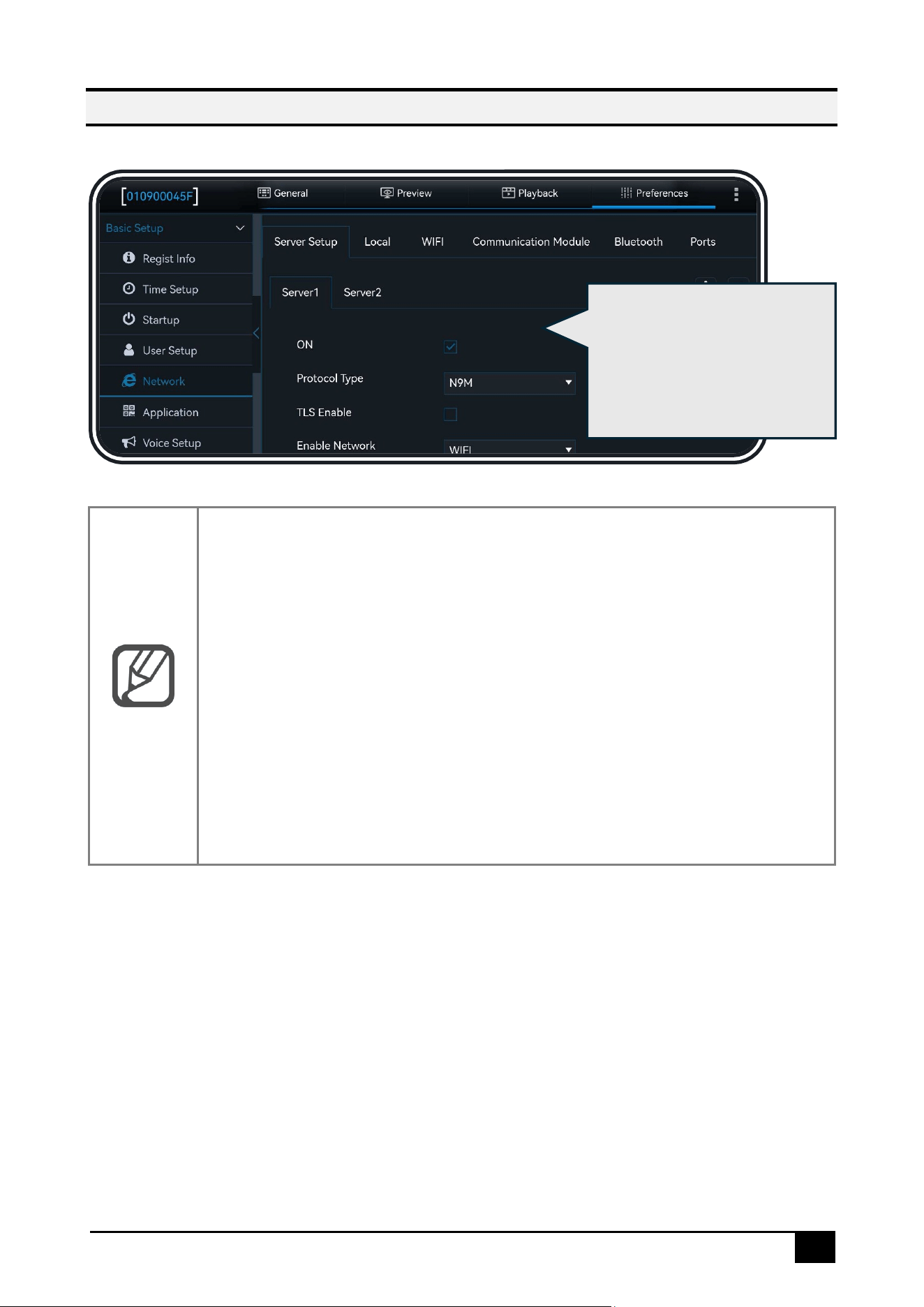
Click [Preferences] – [Basic Setup] – [Network]:
Note
1. [Enable Network]: You can choose between wired network, Wi-Fi,
communication module, or adaptive. Adaptive means the system will
automatically select the available network for platform connection, with
priority given to Wi-Fi > Wired Network > Communication Module
2. During normal device operation, data between the device and the
platform can be transmitted via TLS encryption to ensure the security of
the interaction. (TLS encryption is unavailable in sleep mode.)
3. The registration server and media server addresses and ports must be the
same
4. SMS commands can be used to modify the server parameters. For
specific usage, please consult the relevant personnel
Click [Server Setup] to
add/remove servers and
configure their parameters. A
maximum of 4 servers can be
enabled simultaneously
29
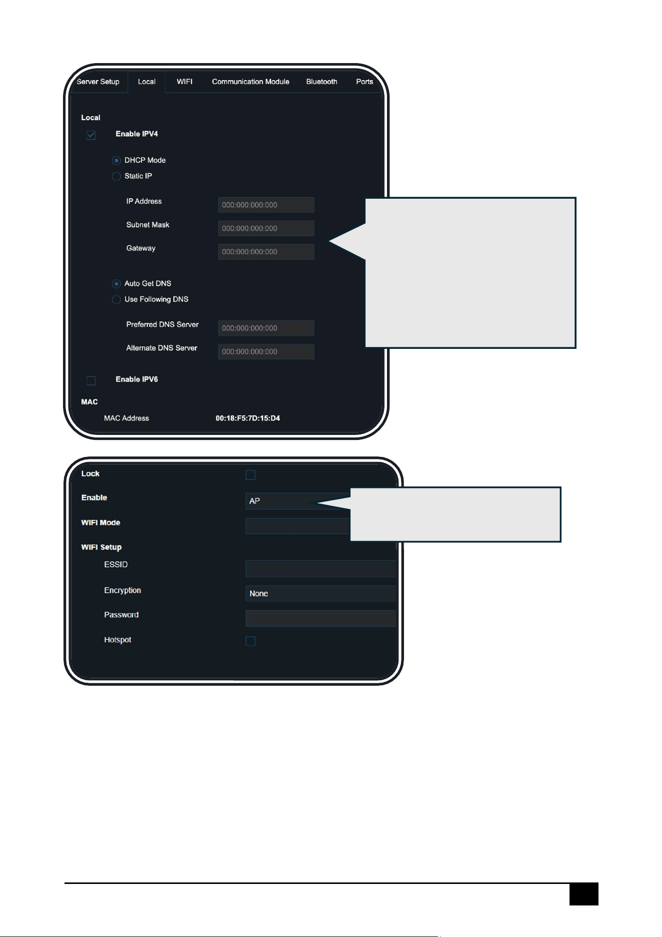
Select and enable AP mode, and
configure the related settings
Click [Local] to configure both IPv4
and IPv6 network protocols. Users
can select automatic IP (DHCP
mode) and DNS retrieval or manually
set the IP address, gateway, and
DNS.
The MAC address info is also
displayed here
30
Note
⚫ [Lock]: When enabled, the Wi-Fi parameters cannot be imported or
modified, and will not be affected by factory reset
⚫ [Enable]:
Disable
Wi-Fi is disabled. The device defaults to AP mode within 3
minutes (configurable) after power on. If no Veyes
connection is made within 3 minutes, the device will exit
AP mode, and the module will enter sleep mode
AP
[WIFI Mode]:2.4G default;
[ESSID]: The name of the device's hotspot (defaults to the
serial number)
[Hotspot]: After enabling the hotspot, mobile devices can
connect to the device's hotspot for internet access. You
can configure the encryption method
[Whitelist]: Only mobile devices with IP addresses in the list
are allowed to connect. You can add up to 5 IP addresses
Client
[ESSID]: The ID and password of an available external Wi-Fi
network. The device will automatically search for nearby
valid Wi-Fi networks and report to the platform through that
network. You can configure the encryption method
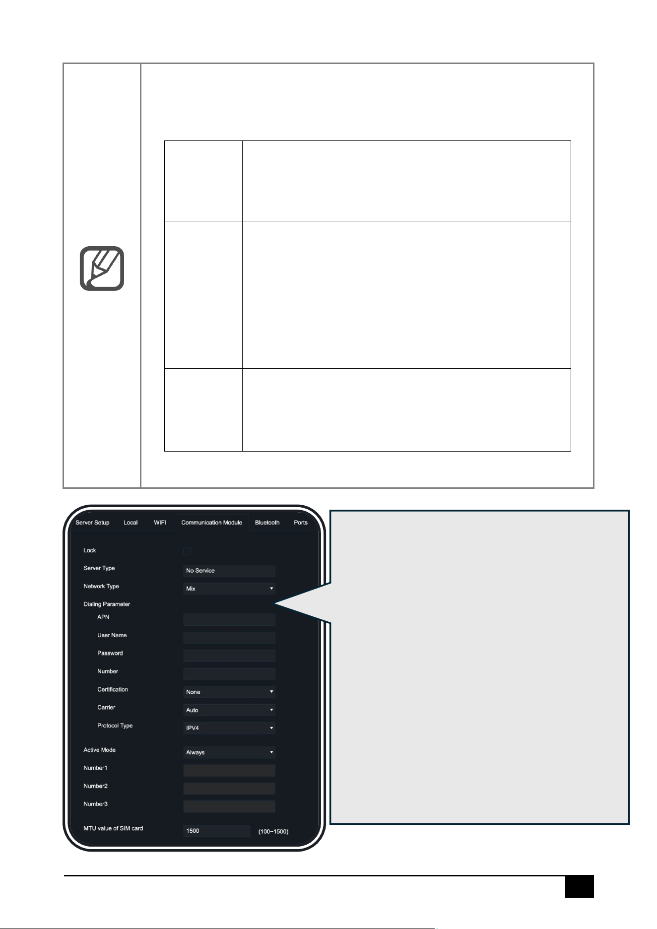
Click [Communication Module] to configure the
communication module settings:
⚫ [Lock]: Same as above, see [WIFI] – [Lock]
⚫ [Dialing Parameter]: Enter the parameters
provided by the SIM card manufacturer. By
default, this field is empty, and if left empty, the
device will use the default dialing parameters
⚫ [Active Mode]: Select [Always] for constant
connection mode; select activation via phone
call/SMS, with a maximum of 3 available
phone numbers; also select [Sensor] switch
activation, where the network module will only
be activated to dial after triggering the IO
sensor
⚫ [MTU value of SIM card]: Default is 1500; the
data is configurable
31
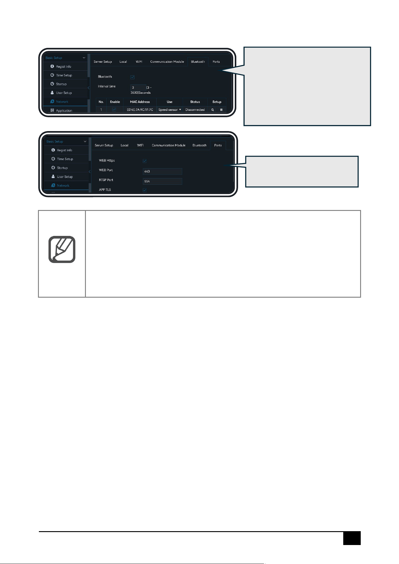
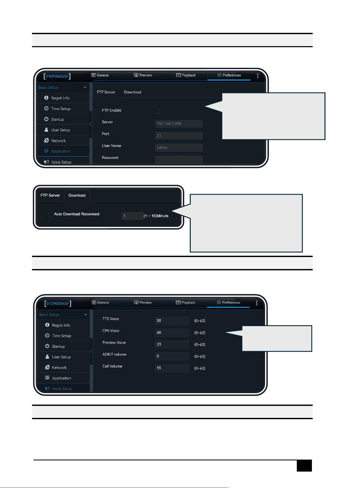
Note
WEB Port: The default is 80, which is used for access via IE.
RTSP Port: The default is 554, supporting real-time preview and playback
through RTSP with a fixed IP.
⚫ RTSP Streaming Format: rtsp://user:pwd@IP:554/mainstreamX (X is the
channel number, starting from 0, such as mainstream0)
⚫ Example: rtsp://admin:admi[email protected]12.17:554/mainstream0
Click [Bluetooth] to search for and
connect to Bluetooth sensors.
Click [Ports]:This interface can
change the port number.
32
Application Setup
Click [Preferences] – [Basic Setup] – [Application]:
Sound Setup
Click [Preferences] – [Basic Setup] – [Voice Setup]:
Telephone Setup
Click [Preferences] – [Basic Setup] – [Telephone Setup]:
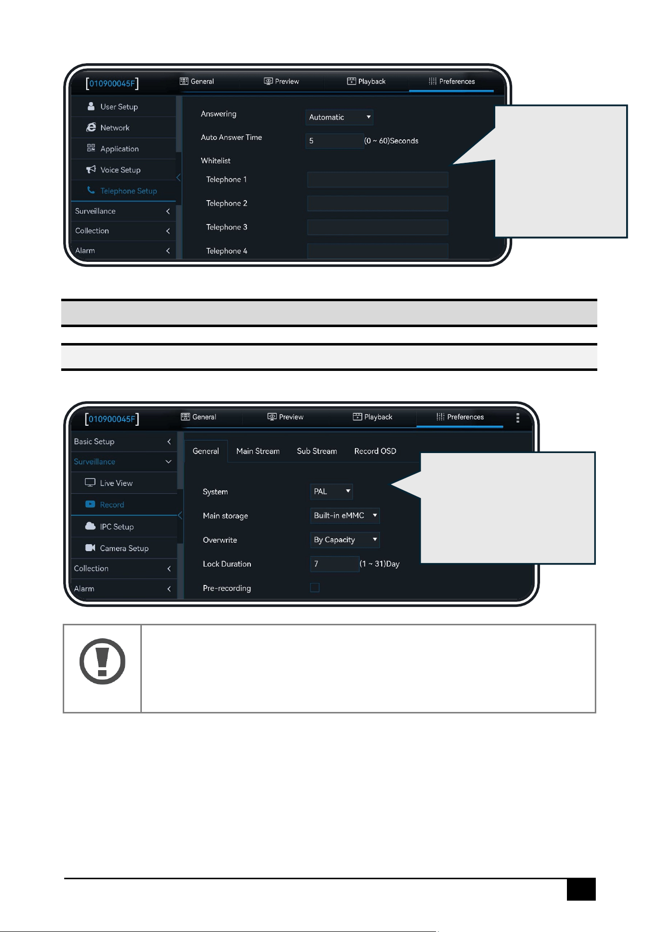
Click [FTP Server], which supports
configuring the FTP server for
uploading or downloading files
and images
Supports volume-
related configurations
Click [Download]: to set the
automatic download reconnection
time, which can be selected
between 1 and 10 minutes, with the
default being 5 minutes.
33
Video Surveillance
Recording Setup
Click [Preferences] – [Surveillance] – [Record]:
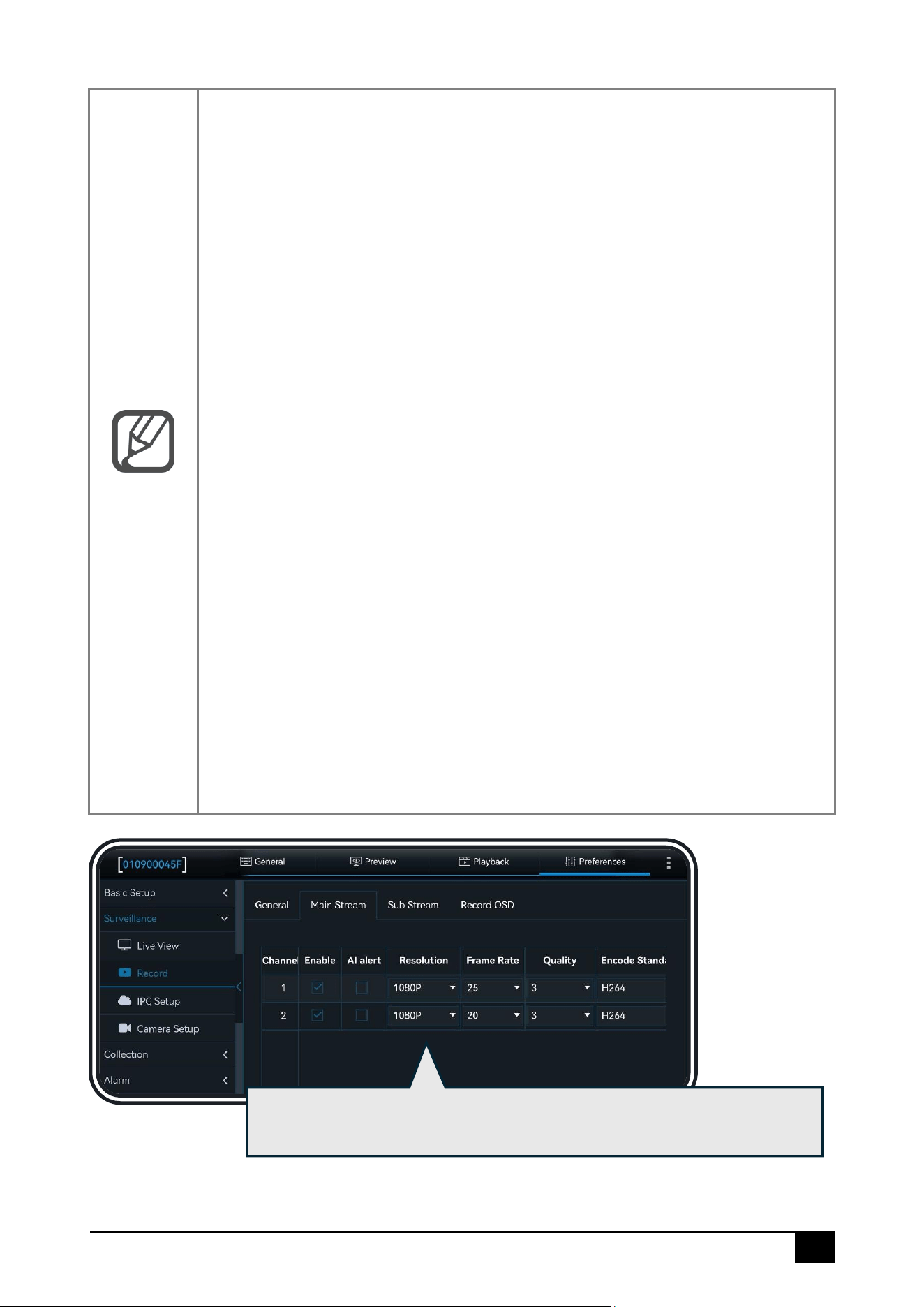
Warning
[System]: The system format includes PAL and NTSC. The system format must
match the external camera format, otherwise, the device will not recognize
it
Supports configuring
the call function.
Allows configuring
auto-answer for calls
from whitelisted
numbers.
Click [General], which
supports configuring system
standards, coverage
strategy, pre-recording logic,
and recording mode
34
Note
[Main Storage]:
Used to select the main card recording type. Since DS100 supports two
storage methods for video recording: built-in eMMC and external Micro SD,
the specific options are as follows:
1. 【Built-in eMMC】: Set the eMMC as the main storage card
2. 【External Micro SD】: Set the Micro SD card as the main storage card .
[Overwrite]:
1. [By Days]: Overwrite by days, storing recordings for n days. If the SD card
is full before n days, overwriting will occur in advance
2. [By Capacity]: Overwrite by capacity, automatically overwriting old
recordings when the remaining capacity is less than 1%
3. [Never]: No overwriting, recording will stop when the storage is full
4. [By Minutes]: The logic is the same as [By Days]
[Pre-recording]:
When in alarm recording, it will link the recordings from a specified time
before the alarm trigger (configurable) for event analysis
[SDRecord Mode]:
Set the recording mode for the secondary card. The definition of the
secondary card is determined by the 【Main storage 】configuration. If
External Micro SD is selected as the Main storage, the built-in eMMC will be
the secondary card. The following description takes the built-in eMMC as the
secondary card as an example:
⚫ [Sub-Record]: The secondary card (built-in eMMC) stores sub-stream
video recordings.
⚫ [Mirror Record]: The secondary card (built-in eMMC) stores main-stream
video recordings, following the settings of the main card (Micro SD).
⚫ [Alarm Backup]: When an alarm is triggered, the secondary card (built-
in eMMC) stores main-stream video recordings.
⚫ [Loop-Record]: The secondary card (built-in eMMC) is in the same state
as the main card (Micro SD) and can be regarded as a single storage
device. Both cards perform cyclic recording, with old files
automatically overwritten, and both store main-stream video
recordings
Click [Main Stream], which supports configuring the following parameters
for each channel in main stream recording
35
Note
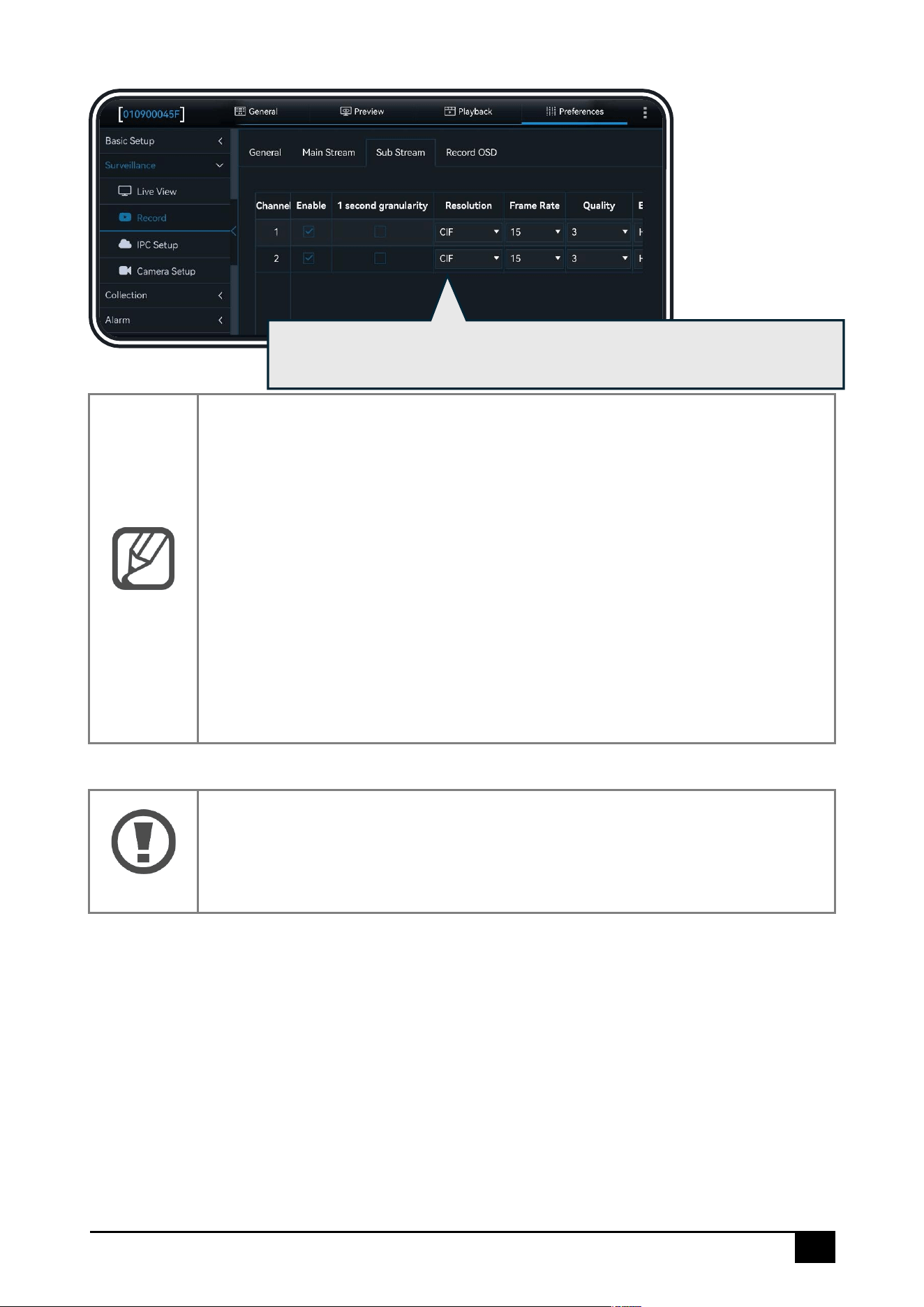
1. [Resolution]: Selectable video resolution
2. [Frame Rate]: Selectable video frame rate
3. [Quality]: Selectable video quality, 1-8
4. [Encode Standard]: Selectable video compression standard, H264/H265
5. [Channel Name]: Modifiable channel name
6. [Record Mode]: Selectable recording mode, startup recording/timed
recording/alarm recording
7. [Audio]: Select whether to enable audio recording
8. [Alarm Quality]: Selectable alarm video quality, 1-8
9. [Encode Mode]: Selectable video encoding mode, CBR/VBR
10. [Audio Coding Format]: Selectable audio compression method
Warning
When the main stream is disabled, the whole video input will be shut down. At
this time, even if the sub-stream is enabled, it won't record the sub-stream.
Click [Sub Stream], which supports configuring the following parameters
for each channel in sub stream recording
36
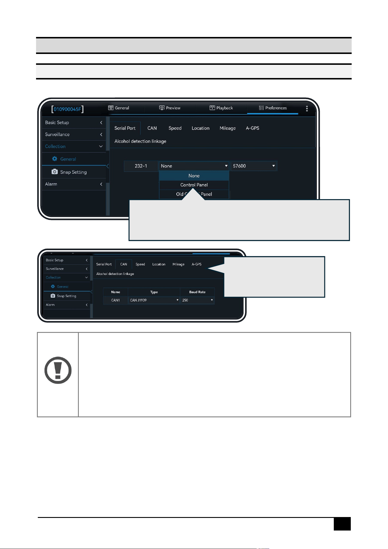
Camera Setup
Click [Preferences] – [Surveillance] – [Camera Setup]:
Warning
The device's default ADAS and DSC screen angles have been set to the
optimal angles at the factory and currently do not support modification.
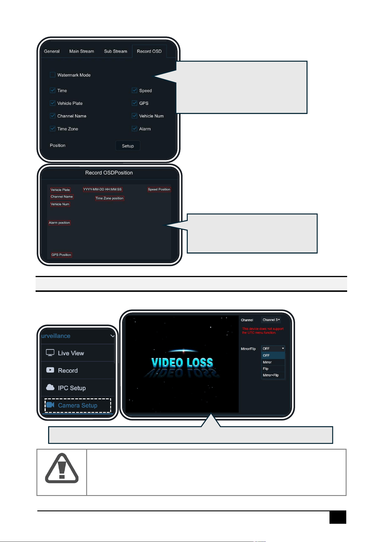
Click [Record OSD], which supports
overlaying the selected information
onto the recording screen, and it can
be displayed in the platform preview
Click [Setup], which supports dragging
to set the overlay position of each
piece of information
You can set the rotation angle, mirroring, and (vertical) flipping for IPC channel's screen
38
Data Collection
General Setup
Click [Preferences] – [Collection] – [General]:
Note
The device supports the standard J1939 protocol. As vehicle manufacturers
may customize certain data fields, the actual obtainable data depends on
real tests. If the needed data isn't supported, you can provide the protocol
for integrated development. For multi-vehicle model adaptation or diverse
data requirements, an OBD power box plus can be optionally configured to
analyze relevant CAN data.
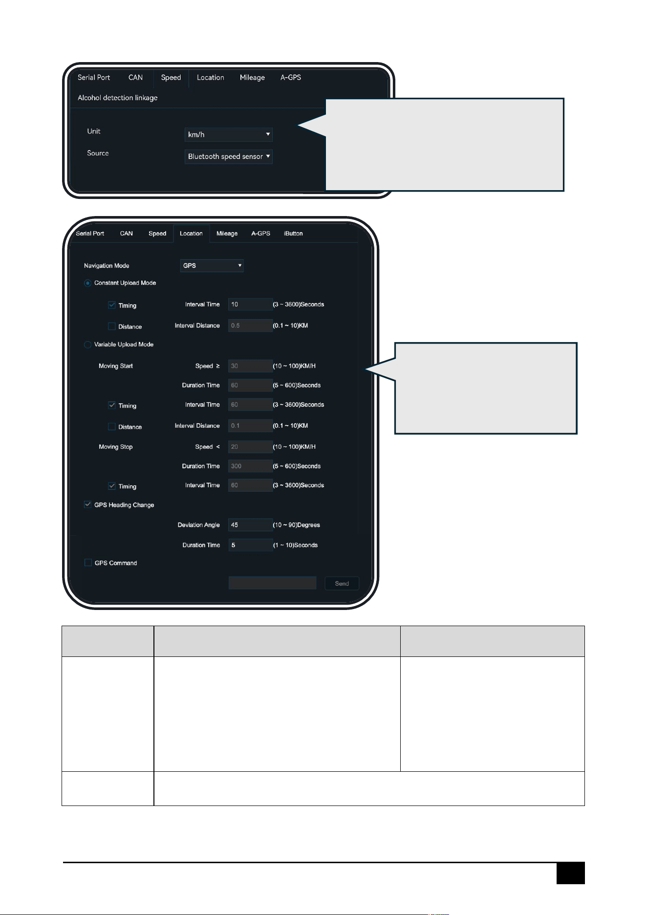
Click [Serial Port], it supports configuring RS232 serial port's purpose
and baud rate (the baud rate will be automatically set, but if there
is an error, you can also adjust it manually)
Click [CAN], it supports
configuring the protocol
type and baud rate for CAN
39
ACC Status
Fixed Reporting
Conditional Reporting
ACC ON
⚫ Timed Reporting: The reporting interval
can be configured
⚫ Distance-Based Reporting: The
reporting distance can be configured.
Both of the above options can be
selected at the same time
Configure [Moving Start]
and [Moving Stop], as
described below
ACC OFF
Sleep Reporting: For more details, please refer to the [Startup Setup]
Click [Speed], which supports configuring
the speed unit and speed source. When
the speed source is set to Mix, it supports
configuring the priority of speed sources
Click [Location], which supports
configuring GPS positioning
mode, reporting mode, and
related parameters
40
Note
⚫ [Moving Start]: When the vehicle speed exceeds a certain value and
stays above it for a specific period, the vehicle is considered to have
started, and reporting will follow the configured time or distance logic
under this option.
⚫ [Moving Stop]: When the vehicle speed drops below a certain value
and stays below it for a specific period, the vehicle is considered to
have stopped, and reporting will follow the configured time logic
under this option.
⚫ [GPS Heading Change]: Reporting will occur when a significant change
in vehicle heading is detected. The angle and reporting interval can
be configured.
⚫ The vehicle's ACC status will be reported along with the GPS
information.
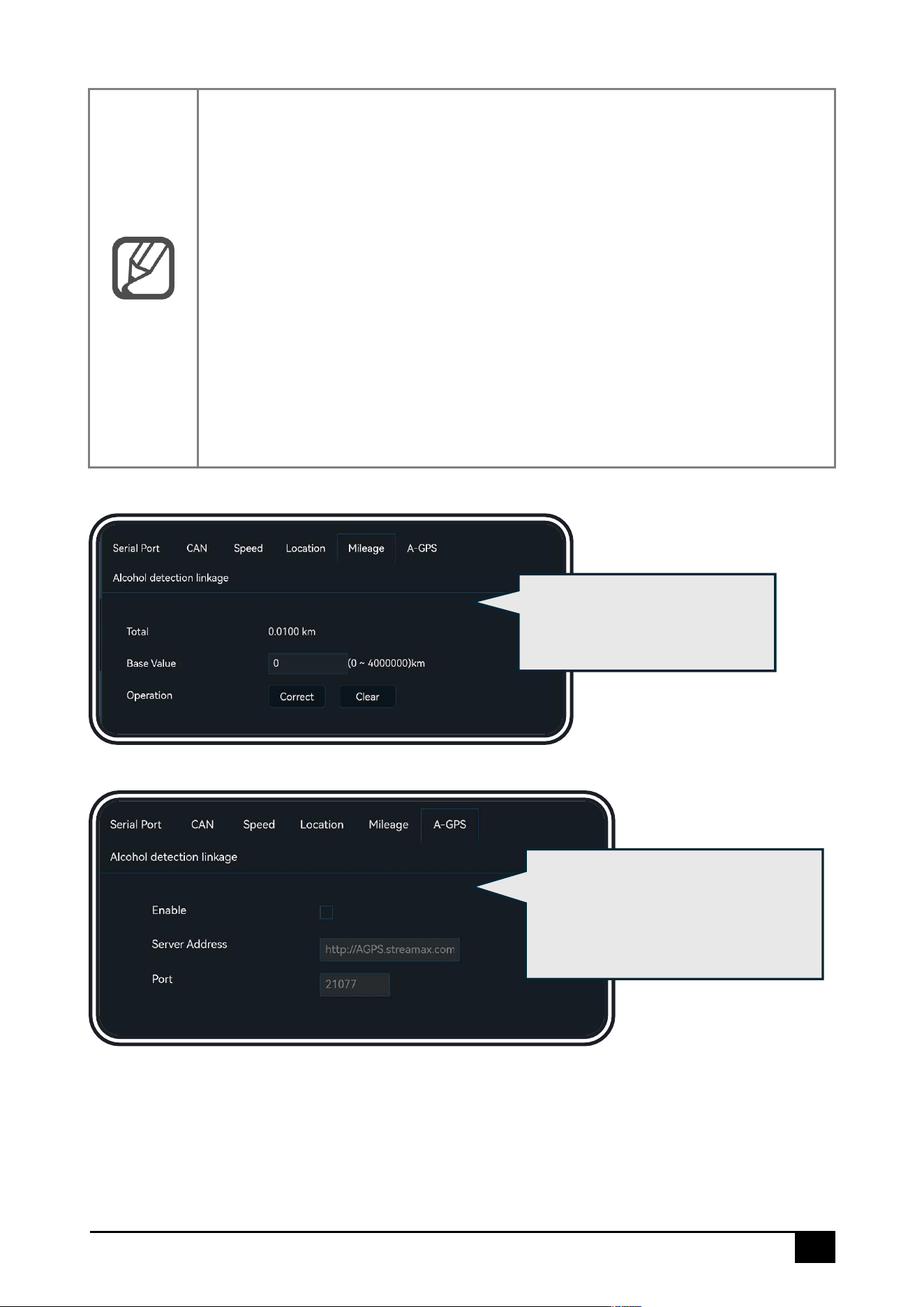
Click [Mileage], which supports
calibrating and resetting the
mileage value
Click [A-GPS] to configure the
server, enabling the device to
obtain real-time location information
from the server in weak signal areas
41
Snap Setup
Click [Preferences] – [Collection] – [Snap Setting]:
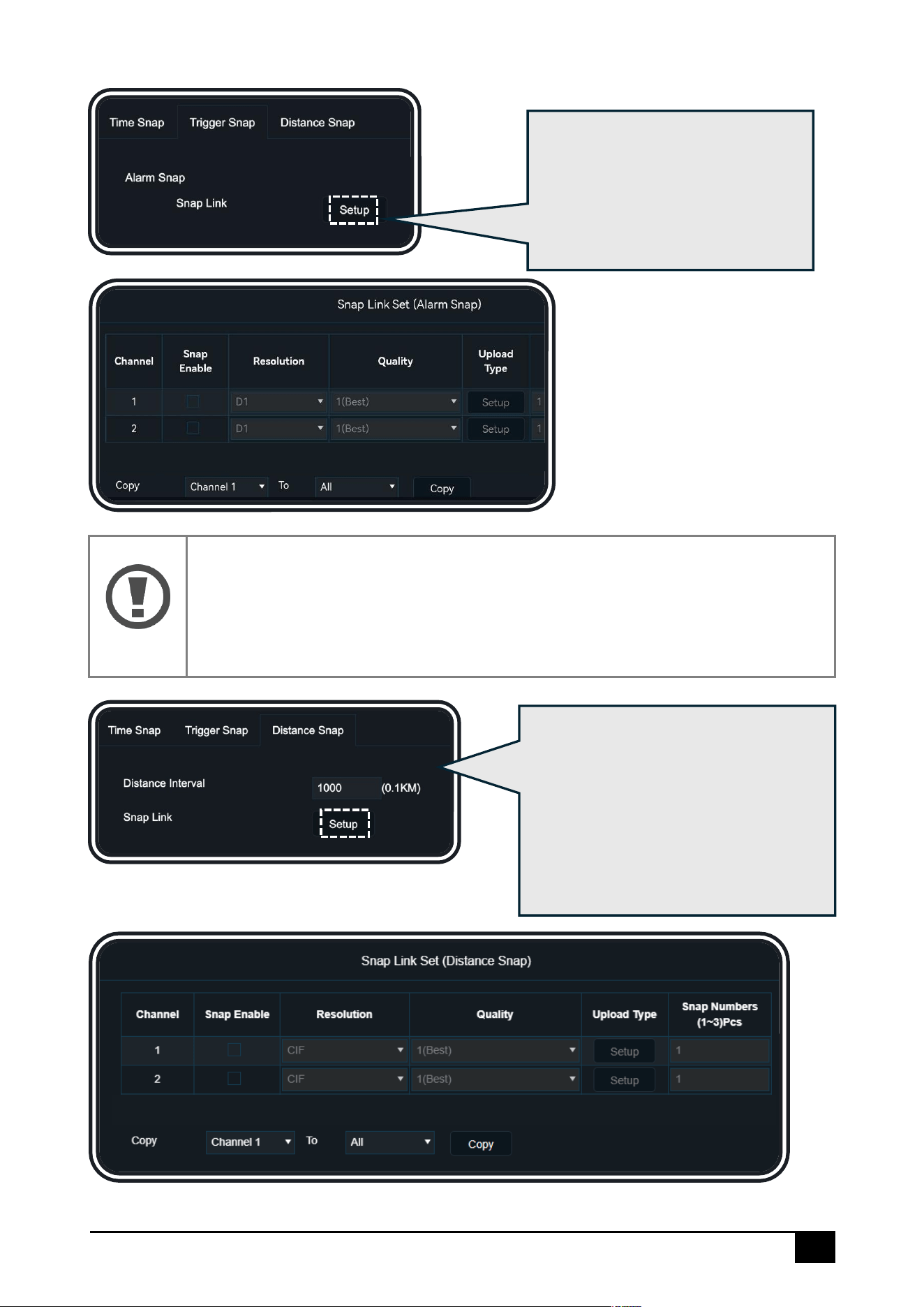
Click [Time Snap], which supports configuring a timed switch strategy.
Each time period can be configured with its own snap parameters:
channel, resolution, image quality, upload method, number of snapshots,
and snapshot interval. A maximum of 8 time periods is supported
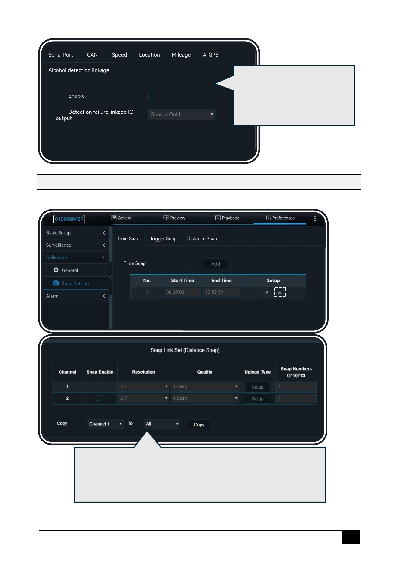
Click [Alcohol detection linkage]
to configure the breathalyzer
peripheral device for driver
alcohol detection.
42
Note
This interface is only related to general(non-AI) alarms, such as IO alarms,
GPS loss alarms, etc. Snapshots will be taken after the alarm is triggered. AI
alarms have a separate snapshot logic and interface, which is unrelated to
this configuration interface.
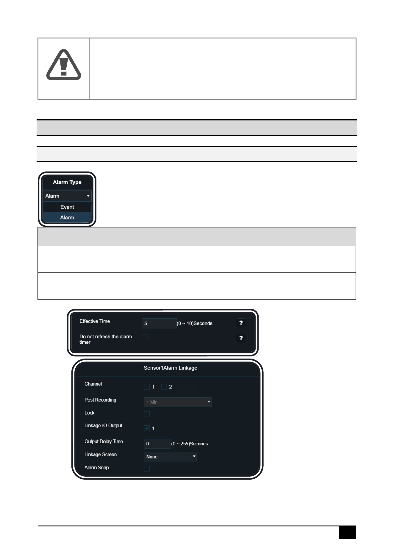
Click [Trigger Snap], which
supports configuring ordinary
alarm snapshots. The configuration
parameters are the same as those
in [Time Snap]
Click [Distance Snap], which supports
configuring distance-based snapshots.
The configuration parameters are
basically the same as those in [Time
Snap], with the only difference being
that distance-based snapshots do not
have a time interval setting
43
Warning
The snapshot function consumes system resources. The average snapshot
frequency of all channels is limited to a maximum of 3 snapshots within 5
seconds. Streamax will not be held responsible for any system resource
issues caused by frequent snapshotting that exceeds this limit.
Alarm Setup
Explanation of General Items for Alarms
All alarms can be configured with two [Alarm Type] options. To avoid
repetitive information, the explanation is provided here:
Alarm Type
Explanation
Alarm
When the type is set to Alarm, the device will record the alarm data
and report it to the platform.
Event
When the type is set to Event, the device will record the alarm data but
will not report it to the platform.
Trigger:
Linkage:
All alarms (including both non-AI alarms and AI alarms) can be configured with [Trigger] and
[Linkage]. Some options are common configurations. To avoid repetitive information, the
explanation is provided here:

44
Configuration
Common Options
Explanation
Trigger
Effective Time
Select a time range. Multiple alarms of the same type
triggered within this time range will be considered as a
single alarm
Trigger
Do not refresh the
alarm timer
By default, this option is unchecked, meaning that
multiple alarms of the same type occurring within a
certain time range (Effective Time) will be considered
as a single alarm, and the Effective Time will reset
accordingly
When checked, multiple alarms of the same type
occurring within the same time range will still be
considered as a single alarm. However, the Effective
Time will not reset. This means that if the total duration
of the alarm exceeds the Effective Time, the alarm will
end, and the total duration will be recorded as the
Effective Time. After the Effective Time has passed, a
new alarm entry will be recorded, starting from the
end of the previous alarm
Linkage
Channel
After an alarm ends, one or more channels can be
selected, and these channels will be marked as alarm
recordings
Linkage
Post Recording
After an alarm ends, the selected channel’s video will
be delayed for a certain period and marked as an
alarm recording
Linkage
Lock
Locked alarm recordings cannot be overwritten until
the recording protection period ends or until manually
unlocked. Even if the storage space is full, they will not
be overwritten
Linkage
Linkage Screen
Configures which camera channel an external monitor
will automatically display when alarms occur
Linkage
Alarm Snap
This option is only available for non-AI alarms. When
checked, it will trigger image capture based on the
previously configured [Snap] settings. For details, refer
to the [Snap] section
45
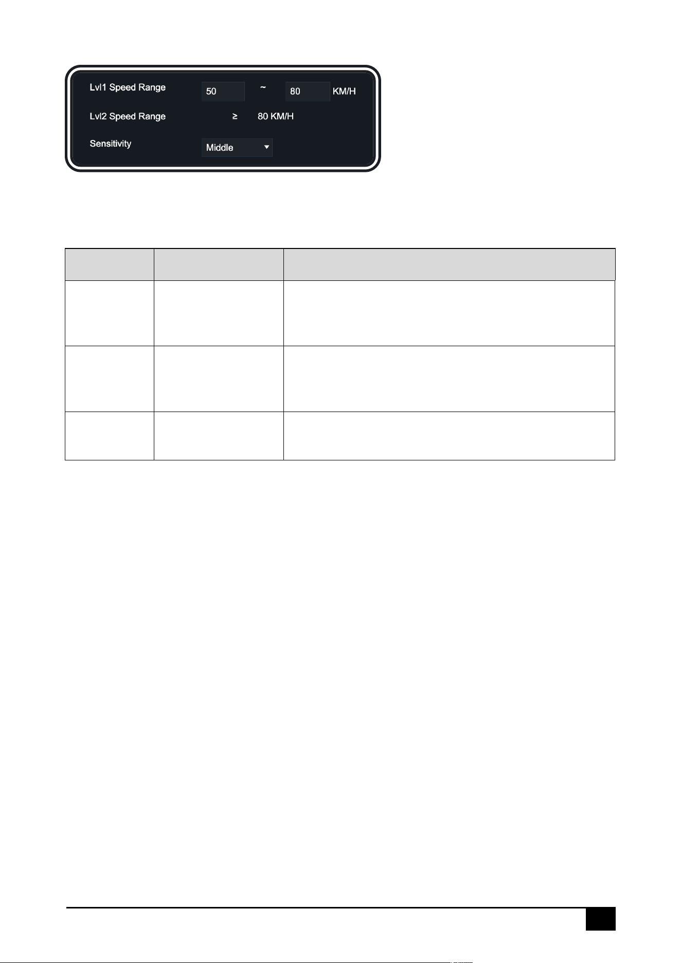
For AI alarms, in addition to some general options already mentioned above, there are also
options that are specific to AI alarms only. To avoid redundant information, the explanation is
provided here:
Configuration
Common Options
Explanation
Trigger
Lvl1 Speed Range
Some AI alarms assess the danger level based on
speed values, categorizing them into Level 1 and
Level 2, which will be differentiated in the audio alerts
Trigger
Lvl2 Speed Range
Some AI alarms assess the danger level based on
speed values, categorizing them into Level 1 and
Level 2, which will be differentiated in the audio alerts
Trigger
Sensitivity
Determine the trigger sensitivity of the alarm
46
Basic Alarms
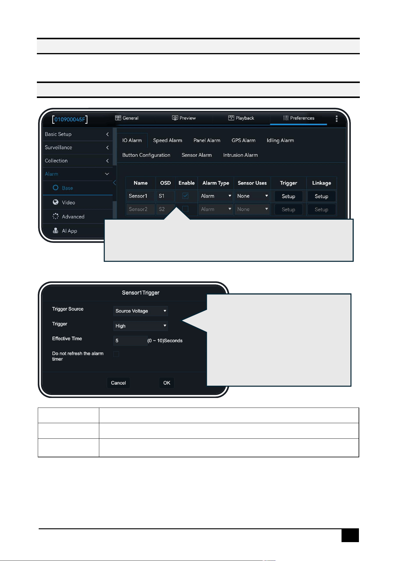
Click [Preferences] – [Alarm] – [Base]:
IO Alarm
High Voltage
Normally low level, triggered by high level
Low Voltage
Normally high level, triggered by low level
Pulse
Normally low level, triggered by a high-to-low or low-to-high level change
The DS100 tail wire has two sensor wires (labeled). Please select the
appropriate [Sensor Uses] based on the specific wiring method, such as
left/right turn signals, reverse signal, etc.
Click [Trigger], which supports configuring
the input source of the IO signal. You can
choose between Voltage or Pulse, as
described in the table below. The options
for Effective Time and Do Not Refresh
Alarm Timer are explained in the general
configuration section
47
Speeding Alarm
Note
This alarm is different from the [Overspeed Alarm] (also known as Speed
Limit Sign Alarm)
Panel Button Alarm
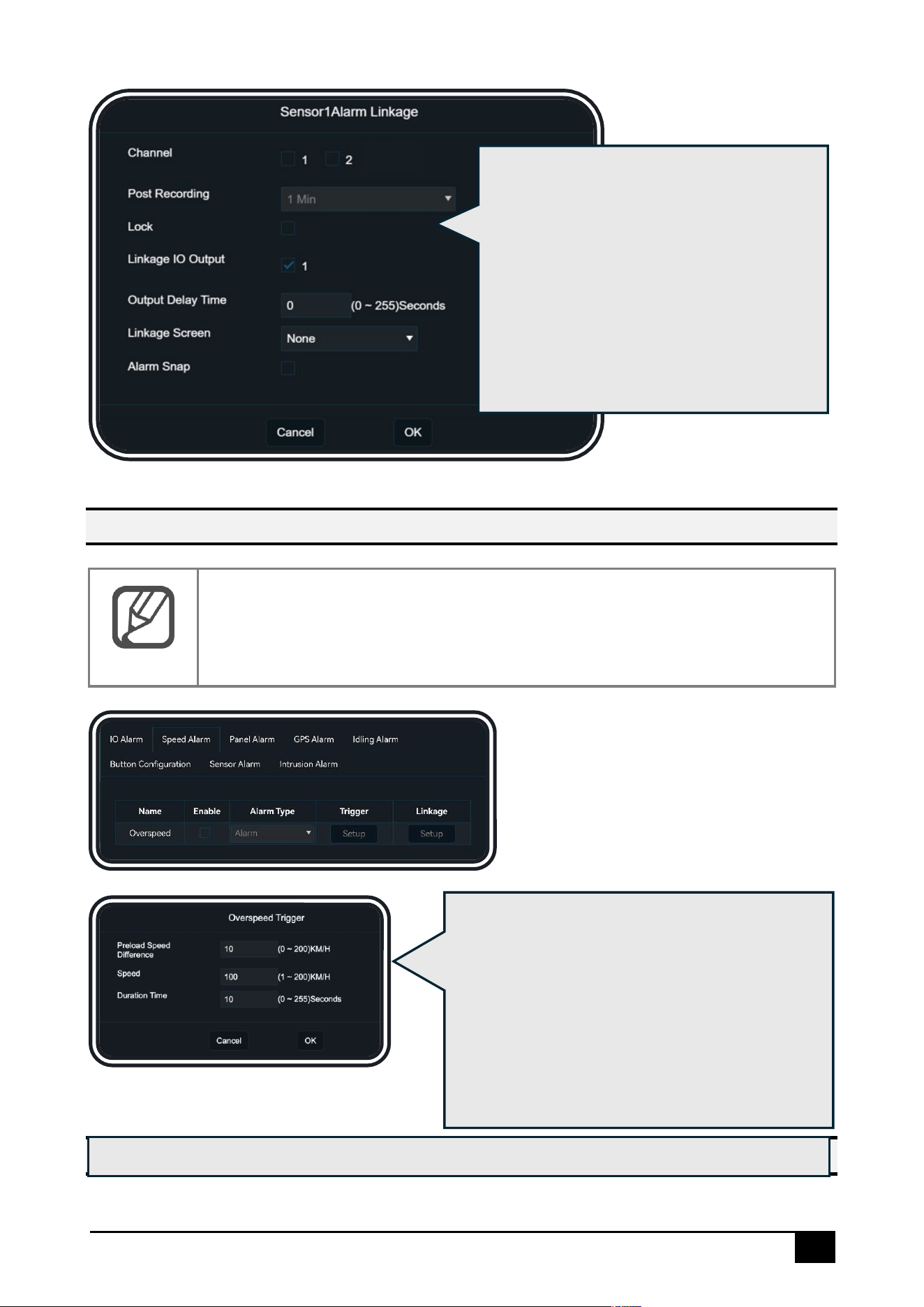
Click [Linkage] to configure the linkage
function of IO signals. The DS100 tail wire is
equipped with a Sensor Out wire (labeled
12V out, which can drive the seat shaker).
Configuring [Linkage IO Output] and
[Output Delay Time] allows setting the IO
output and its duration after an IO alarm is
triggered. For details on other options,
please refer to the description of general
items.
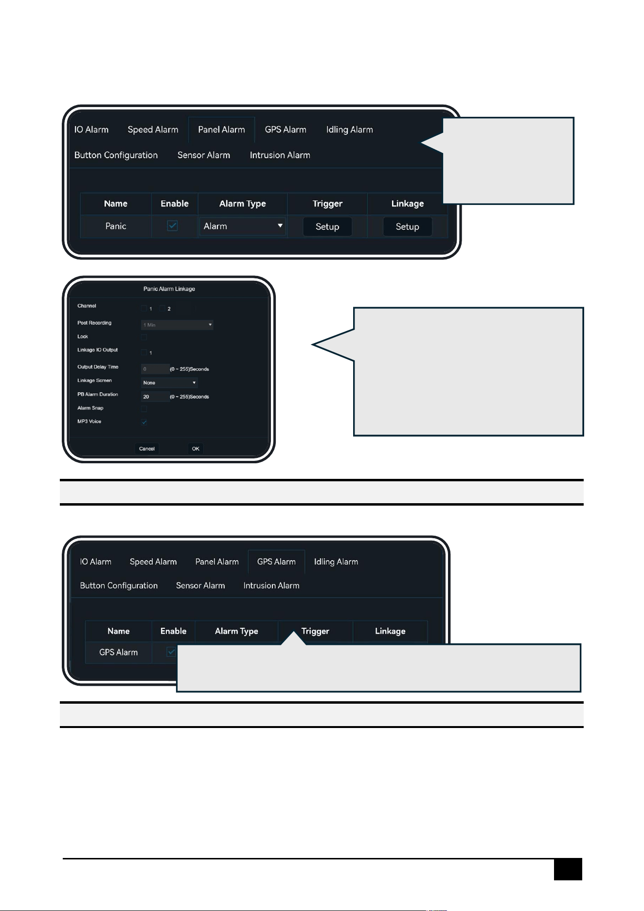
Click [Trigger], when the vehicle speed exceeds
the configured [Speed] - [Preload Speed
Difference], a pre-warning and voice alert will be
triggered. If the vehicle speed exceeds the
configured [Speed], a voice alert will be
triggered. If the driver does not slow down within
the configured [Duration Time], the alarm will be
reported to the platform
Click [Linkage], for option details, please refer to the general configuration description
48
The DS100 panel has an Emergency Alarm Button, which can trigger a panel button alarm with
a single press.
GPS Alarm
A GPS alarm will be triggered when the GPS signal is lost
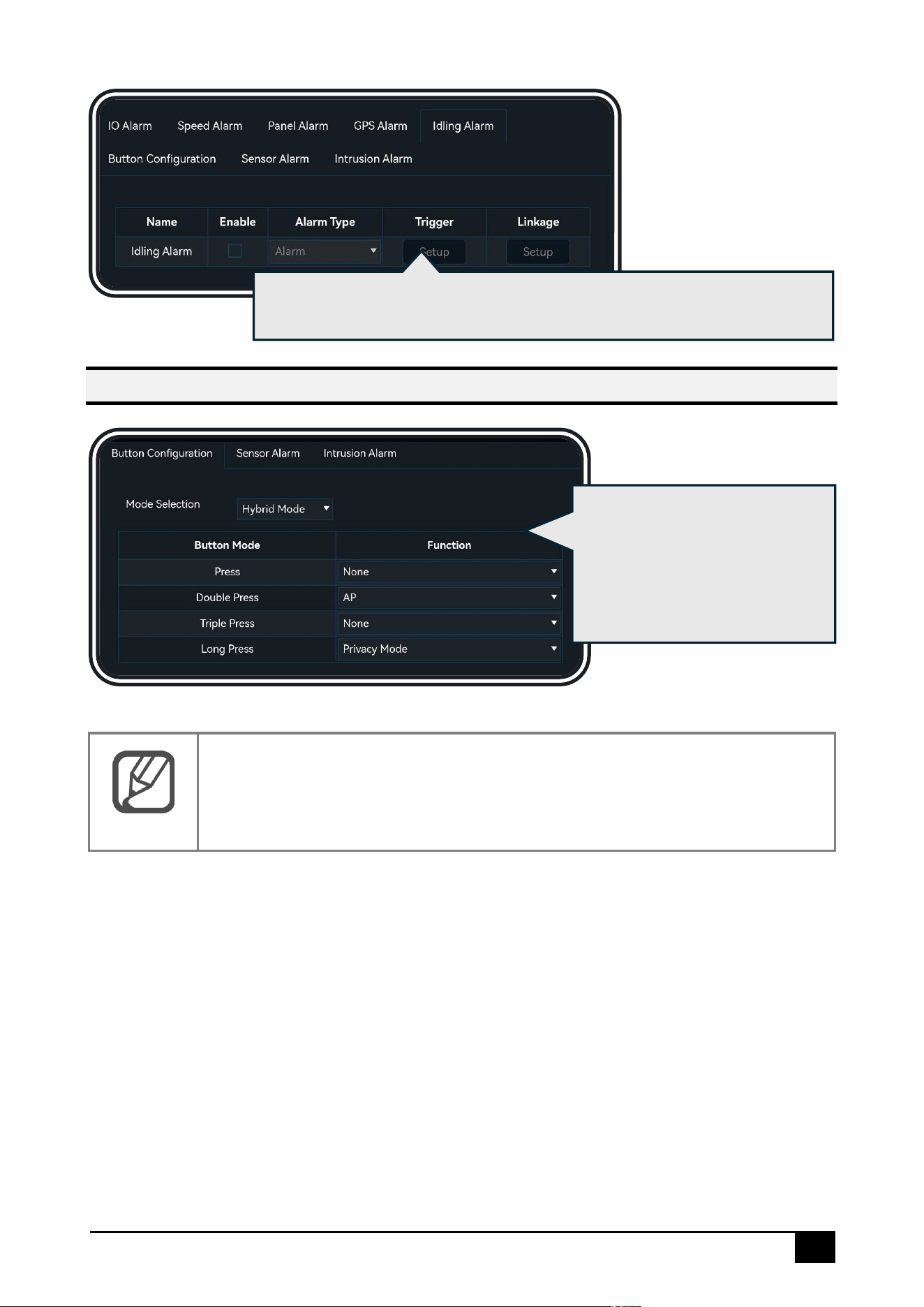
Idling Alarm
An Idling alarm will be triggered when the vehicle is idling
Click [Linkage], you can set the panel
button alarm duration using [PB Alarm
Duration]. Checking [MP3 Voice] will
enable a voice prompt when the alarm
is triggered. For other options, please
refer to the general configuration
description
Click [Trigger], for
option details, please
refer to the general
configuration
description
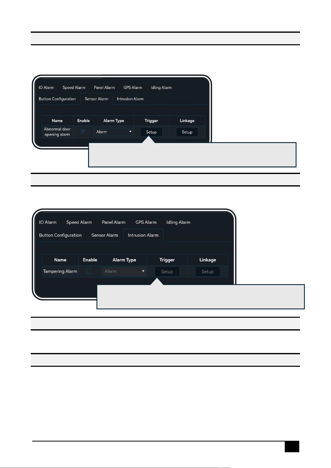
Click [Trigger] and [Linkage], for option details, please refer to the general
configuration description
49
Button Configuration
Note
The Emergency Alarm Button is independent and requires no extra setup—
any press (single, double, or long-press) will activate the alarm.
Click [Button Configuration] to
set the function and trigger
mode (e.g., single-click,
double-click, or long-press) for
the device's physical button
Click [Trigger] and [Linkage], for option details, please refer to the general
configuration description
50
Sensor Alarm
When the truck door is abnormally opened, an "abnormal door opening alarm" will be
triggered.
Intrusion Alarm
When the device experiences violent shaking (e.g., removing the device), a tampering alarm
will be triggered.
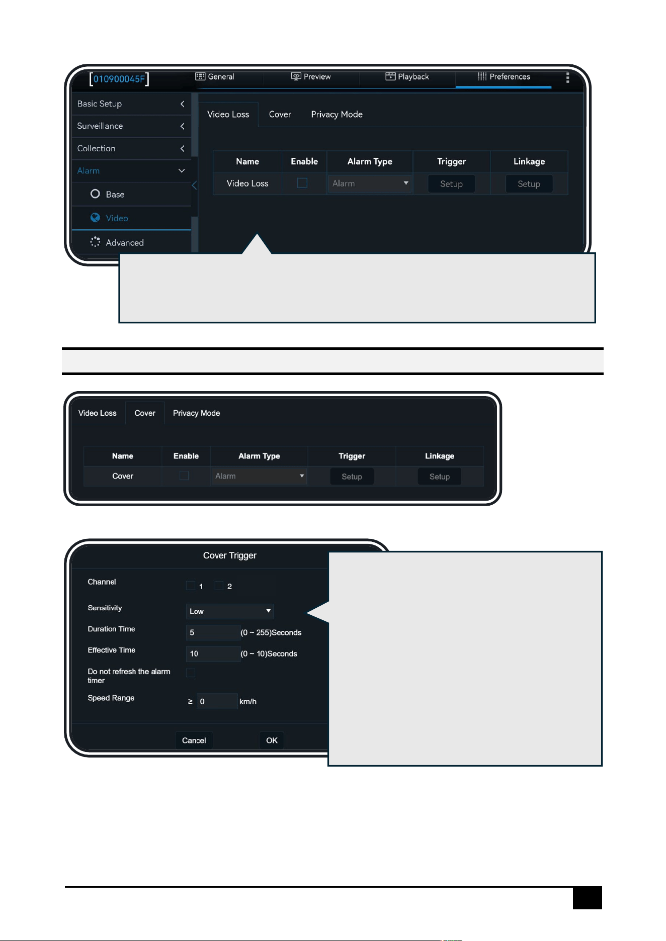
Video Alarms
Click [Preferences] – [Alarm] – [Video]:
Video Loss Alarm
A Video Loss Alarm will be triggered when the camera experiences a malfunction or is
physically disconnected
Click [Trigger] and [Linkage], for option details, please refer to the general
configuration description
Click [Trigger] and [Linkage], for option details, please refer to the general
configuration description
51
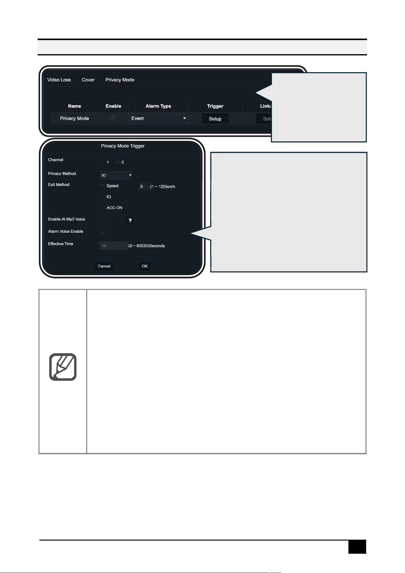
Camera Cover Alarm
Click [Trigger], select the channels for which the
Camera Cover Alarm should be enabled. It
supports configuring the sensitivity of the alarm
trigger; it also supports setting the alarm trigger
based on [Duration Time] and [Speed Range],
meaning that when the vehicle speed exceeds
a certain value and the device detects
camera obstruction for a specified duration,
the alarm will be triggered. For other options,
please refer to the general configuration
description
Click [Trigger], select the channels for which the Video Loss Alarm should be
enabled. For other options, please refer to the general configuration description.
Click [Linkage], for option details, please refer to the general configuration
description
52
Privacy Mode
Note
Privacy Mode Entry Methods:
⚫ If IO is selected, the IO function must be set to privacy mode. For
details, refer to the [IO Alarm] section
⚫ If ACC OFF is selected, privacy mode will be activated when the
vehicle’s ACC is turned off
Privacy Mode Exit Methods:
⚫ If Speed is selected, a speed value must be configured, meaning
privacy mode will be disabled when the vehicle speed exceeds the set
value
⚫ If IO is selected, the IO function must be set to privacy mode. For
details, refer to the [IO Alarm] section
⚫ If ACC ON is selected, privacy mode will be disabled when the
vehicle’s ACC is turned on
When privacy mode is
enabled for a channel,
recording and audio
recording for that
channel will be turned off
Click [Trigger], select the channels for which
privacy mode should be enabled. You can
choose the entry/exit method for privacy
mode, enable [AI Mp3 Voice] to allow AI
algorithm detection and AI alarms with
voice prompts while in privacy mode, and
enable [Alarm Voice Enable] for voice
announcements when entering/exiting
privacy mode
53
Advanced Alarms
Click [Preferences] – [Alarm] – [Advanced]:
Harsh Driving Alarm
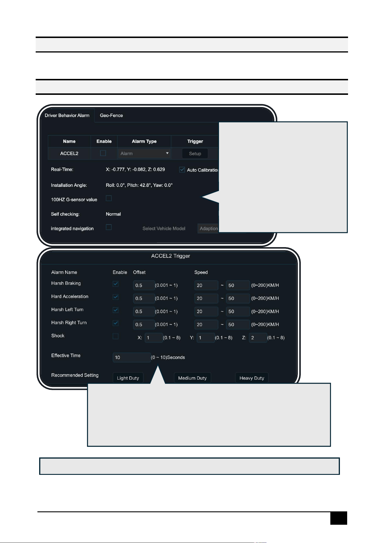
ACCEL2 (Aggressive Driving Alarm) is
triggered by the G-Sensor which
supports automatic or manual
calibration for optimal sensitivity. For
improved accuracy, enable the
[Integrated Navigation] button to
select the vehicle type, allowing the
system to assess alerts more precisely
based on combined sensor data
Click [Trigger], you can adjust the [Offset] value to modify the sensitivity of
each alarm: the smaller the offset value, the more sensitive the alarm
detection. You can also select the vehicle type to use the corresponding
inertial sensor model for optimal detection performance. For other options,
please refer to the general configuration description
Click [Linkage], for option details, please refer to the general configuration description
54
Geo-Fence Alarm
Temperature and Humidity Alarm
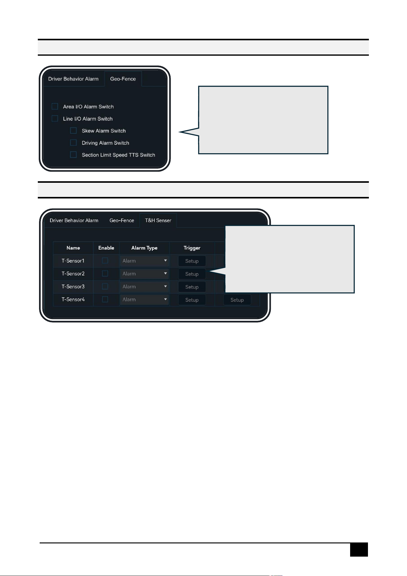
Click [Geo-Fence], in this interface,
you can select the entry/exit fence
or route handling strategy. This
feature requires integration with the
CEIBA2 platform or FT Cloud
platform
Click [H&T Sensor]. In this interface,
you can configure the temperature
and humidity alarm thresholds. This
feature requires connection to a
temperature and humidity sensor.
platform
55
AI Alarms
Click [Preferences] – [Alarm] – [AI App]:
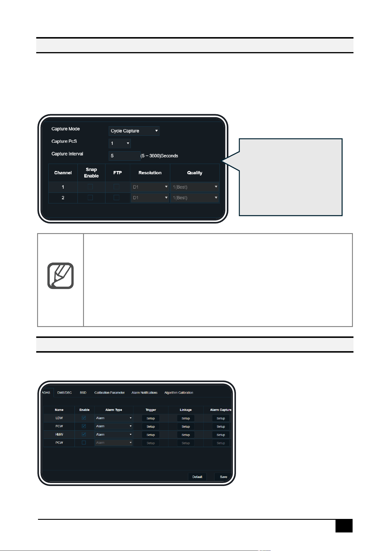
You can set the snapshot logic when an AI alarm is triggered. AI alarms have their own
snapshot logic, which is independent of the Snap Setting section. For each AI alarm, click
[Alarm Capture] → [Setup]:
Note
Capture Mode:
⚫ Single Capture: Only one snapshot will be taken each time, and the
total number of snapshots is determined by [Capture PcS], while the
interval between each snapshot is determined by [Capture Interval]
⚫ Cycle Capture: The number of snapshots taken each time is
determined by [Capture PcS], and the interval between each
snapshot is determined by [Capture Interval], until the alarm ends
ADAS Alarms
Click [Preferences] – [Alarm] – [AI App] – [ADAS]:
In this interface, you can set
the snapshot mode, number
of snapshots, snapshot
interval, snapshot channel,
and the resolution and
quality of the snapshot
images
56
LDW Alarm
FCW Alarm
HMW Alarm
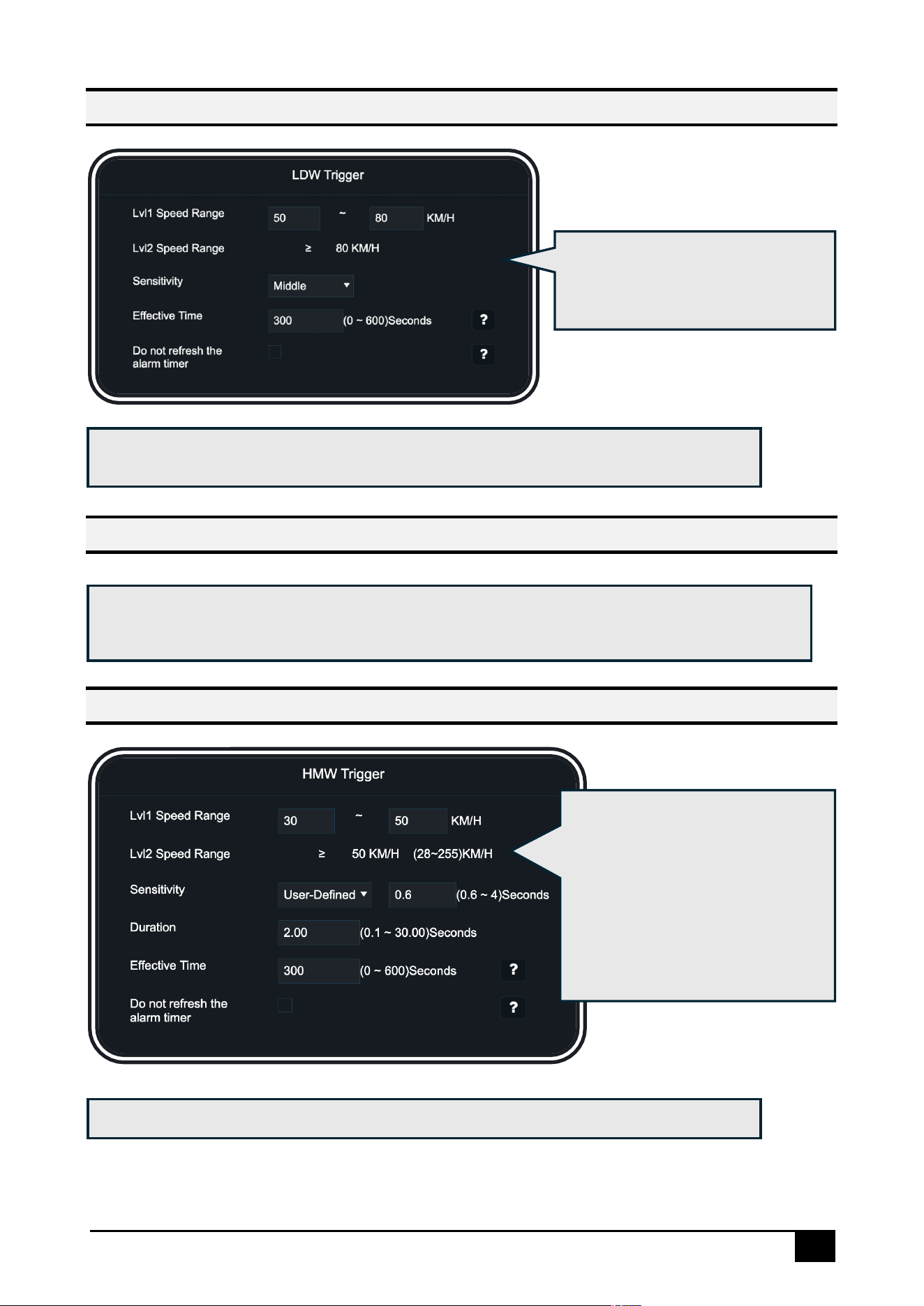
Click [LDW]-[Trigger], option
details, please refer to the general
configuration description
Click [LDW]-[Linkage], for option details, please refer to the general configuration
description
Click [Trigger] and [Linkage], for option details, please refer to the general configuration
description
Click [Trigger], you can set
[Duration] to determine how long
the vehicle should maintain a
close distance before triggering
an alarm. For other options,
please refer to the general
configuration description
Click[HMW]-[Linkage], for option details, please refer to the general configuration
description

57
PCW Alarm
Click [Trigger] and [Linkage], for option details, please refer to the general configuration
description
58
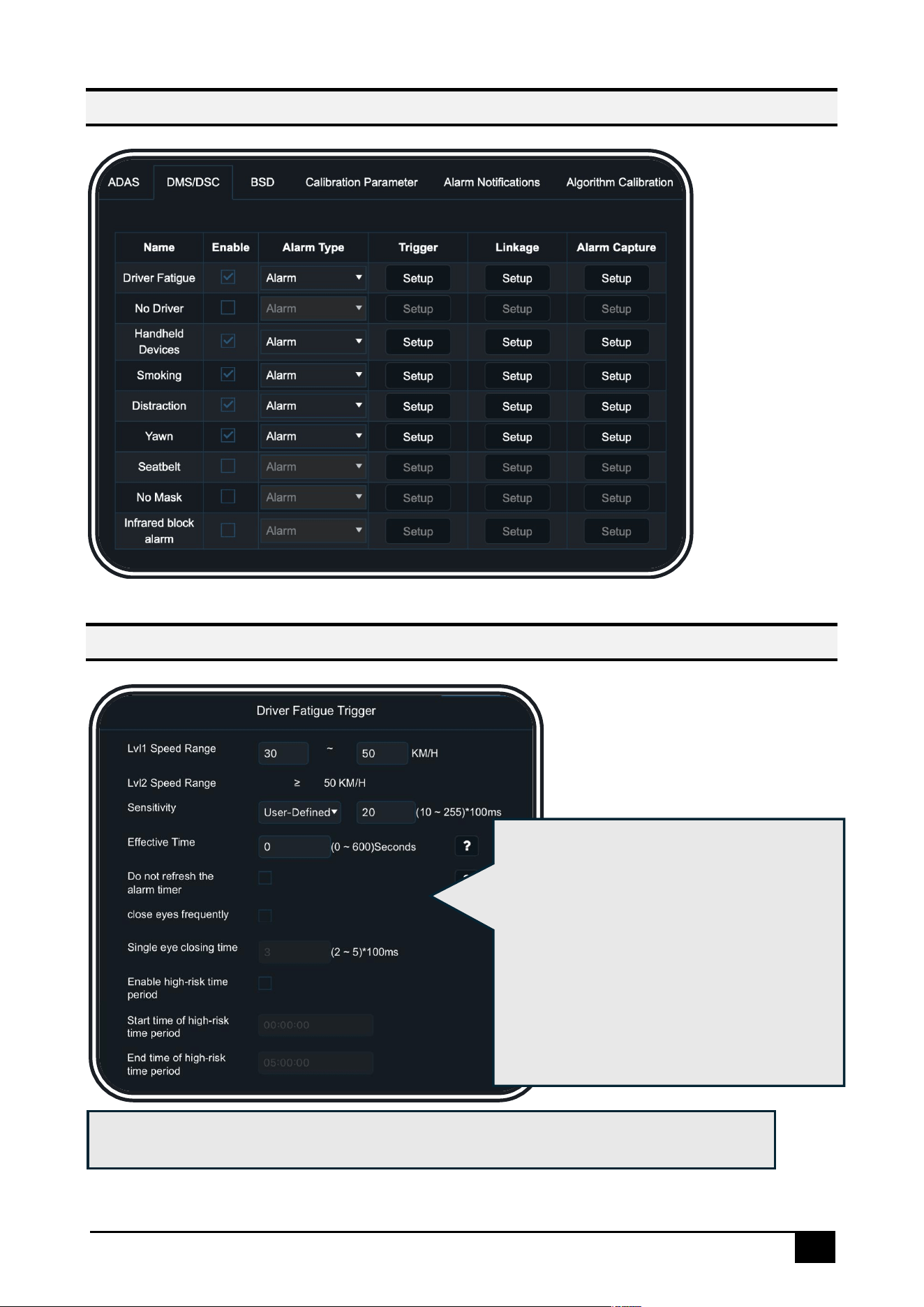
DMS/DSC Alarms
Driver Fatigue Alarm
Click [Trigger], you can enable frequent
eye-closure detection and set the duration
of a single eye closure. If the set threshold is
met, an alarm will be triggered. You can
also enable high-risk time periods and set a
time range, during which the alarm
sensitivity will increase, and the threshold
will be lowered. For other options, please
refer to the general configuration
description.
Click [Linkage], for option details, please refer to the general configuration description
59
No Driver Alarm
Handheld Device Alarm
Smoking Alarm
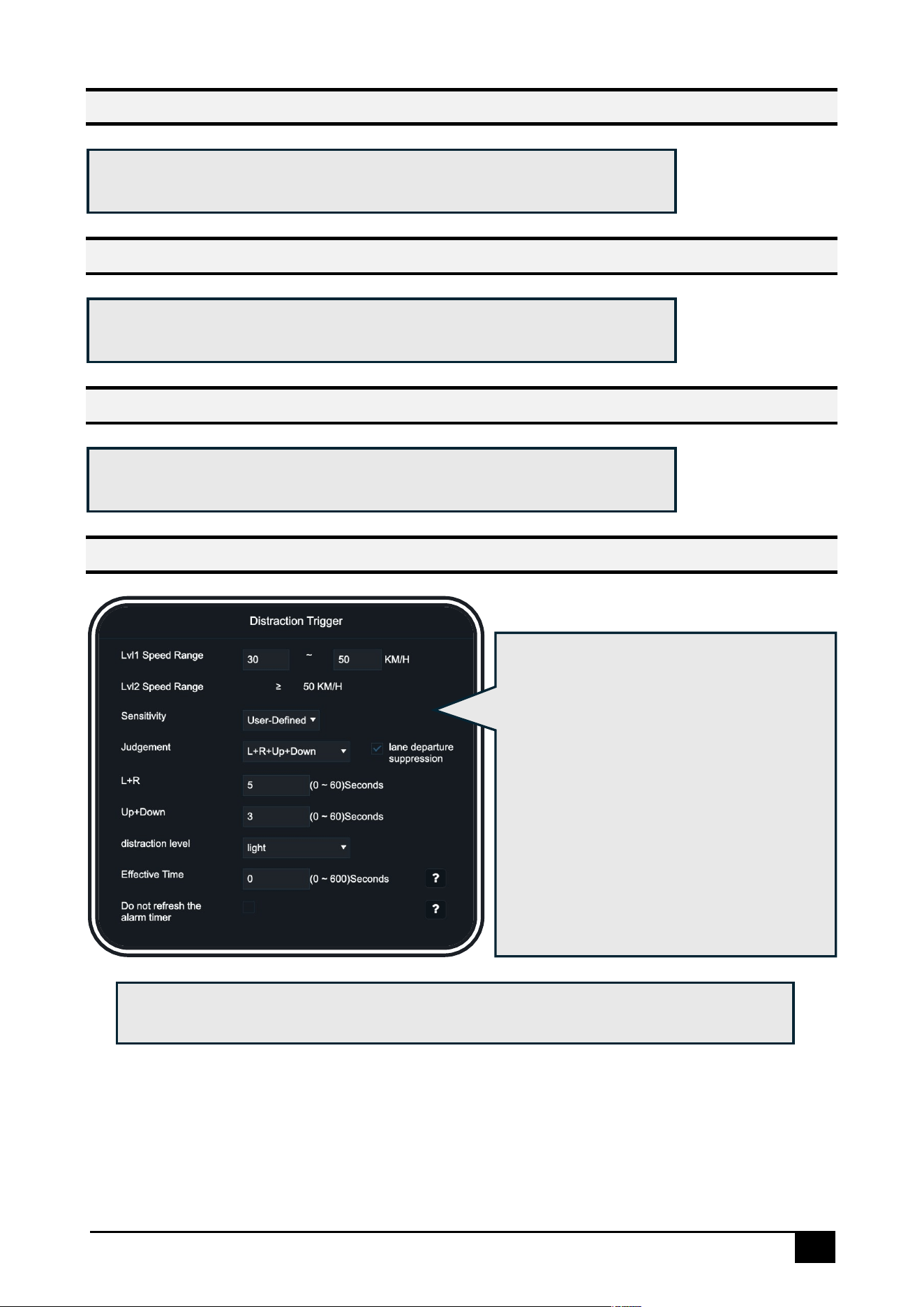
Distraction Alarm
Click [Trigger] and [Linkage], for option details, please refer to the general
configuration description
Click [Trigger], you can set the criteria for
determining driver distraction, whether it
is left/right distraction or up-down
distraction, and you can configure
individual sensitivity settings respectively.
You can also check [Lane Departure
Suppression] to reduce false alarms
caused by the driver turning their head to
check mirrors or road conditions during
large turns. For other options, please refer
to the general configuration description.
Click [Linkage], for option details, please refer to the general configuration description
Click [Trigger] and [Linkage], for option details, please refer to the general
configuration description
Click [Trigger] and [Linkage], for option details, please refer to the general
configuration description
60
Yawn Alarm
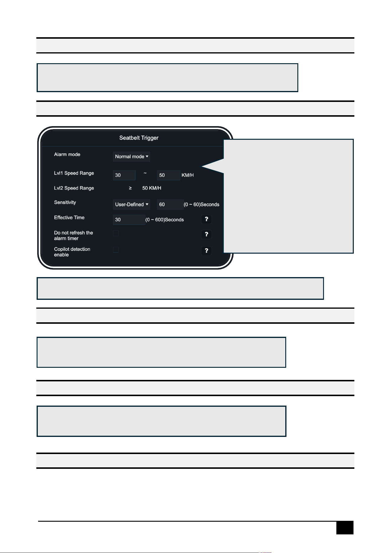
Seatbelt Alarm
No Mask Alarm
Infrared Block Alarm
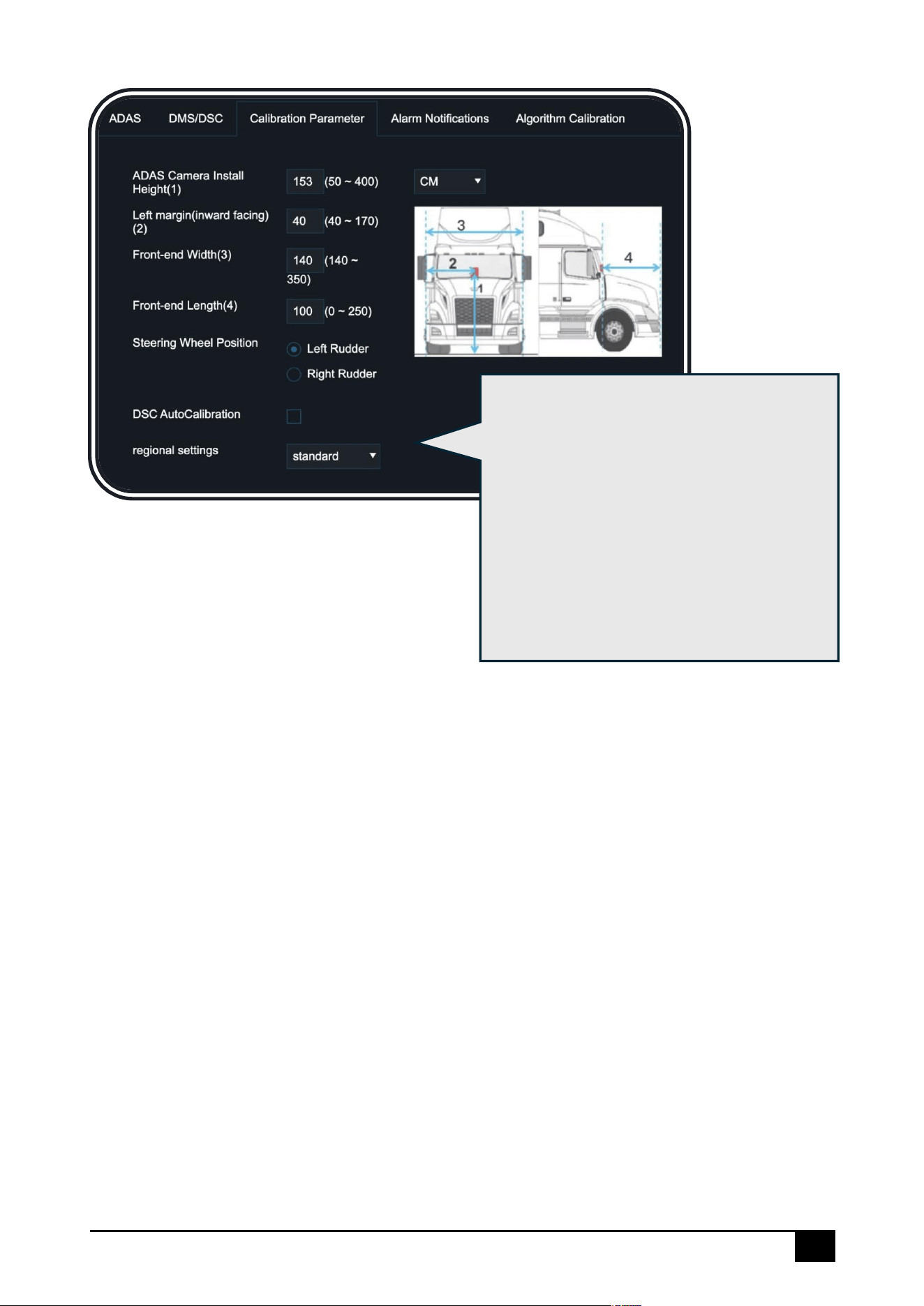
Calibration Parameter
Click [Trigger] and [Linkage], for option details, please refer to the general
configuration description
Click [Trigger], you can choose
between Normal Mode or Regular
Inspection Mode. When selecting
Regular Inspection Mode, you can
configure the detection interval.
You can also enable copilot
seatbelt detection. For other
options, please refer to the general
configuration description
Click [Linkage], for option details, please refer to the general configuration description
Click [Trigger] and [Linkage], for option details, please refer to the general
configuration description
Click [Trigger] and [Linkage], for option details, please refer to the general
configuration description
61
In this interface, you can configure the
installation position of the dashcam.
Accurate position information improves the
accuracy of the ADAS algorithm.
Additionally, you can configure the steering
wheel position (left-hand or right-hand
drive), region (to enhance the recognition
accuracy of stop signs and speed limit
signs), and whether to enable DSC
automatic calibration
62
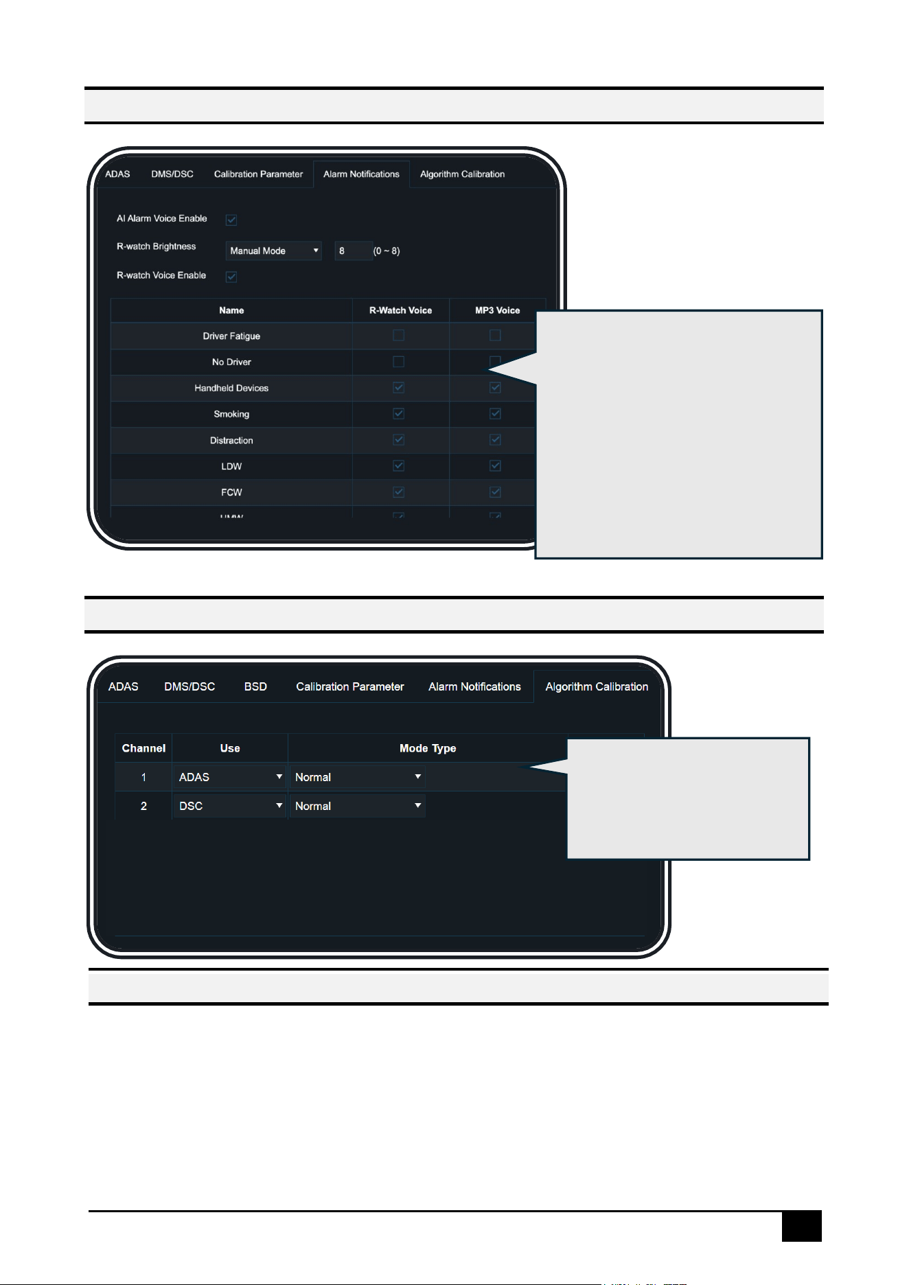
Alarm Notification
Algorithm Calibration
In this interface, you can enable
the alarm voice for the main unit.
You can also enable the voice and
configure the brightness for the
external R-Watch sound and light
alarm. Additionally, you can
individually enable voice prompts
for all AI alarms in the lower table
In this interface, you need to
select the algorithm usage for
each channel according to
the actual situation
Special Note
This product needs to be installed by professionals to prevent the risk of it falling off.
When this product is in direct sunlight, the surface temperature will exceed 60 degrees . Please do not touch it to prevent burns.
This device complies with Part 15 of the FCC Rules. Operation is subiect to the following two conditions: (1) this device may not
cause harmful interference(2) this device must accept any interference received, including interference that may cause undesired
operation.

FCC Caution.
This device complies with part 15 of the FCC Rules. Operation is subject to the following two
conditions:
(1) This device may not cause harmful interference, and
(2) this device must accept any interference received, including interference that may cause
undesired operation.
Any Changes or modifications not expressly approved by the party responsible for compliance
could void the user's authority to operate the equipment.
Note: This equipment has been tested and found to comply with the limits for a Class B digital
device, pursuant to part 15 of the FCC Rules. These limits are designed to provide reasonable
protection against harmful interference in a residential installation. This equipment generates
uses and can radiate radio frequency energy and, if not installed and used in accordance with the
instructions, may cause harmful interference to radio communications. However, there is no
guarantee that interference will not occur in a particular installation. If this equipment does
cause harmful interference to radio or television reception, which can be determined by turning
the equipment off and on, the user is encouraged to try to correct the interference by one or
more of the following measures:
-Reorient or relocate the receiving antenna.
-Increase the separation between the equipment and receiver.
-Connect the equipment into an outlet on a circuit different from that to which the receiver is
connected.
-Consult the dealer or an experienced radio/TV technician for help.
FCC Radiation Exposure Statement:
This equipment complies with FCC radiation exposure limits set forth for an uncontrolled
environment. This equipment should be installed and operated with minimum distance 20 cm
between the radiator & your body.