FEX12TB
2.4GHz band module
Instruction Manual

FCC Warning
CAUTION:
To assure continued FCC compliance:
1. Any changes or modifications not expressly approved by the grantee of this device could
void the user's authority to operate the equipment.
2. This equipment complies with FCC radiation exposure limits set forth for an uncontrolled
environment.
i. When used in stationary receivers,
This equipment should be installed and operated with minimum distance 20cm
between the radiator & your body.
ii. When used in remote control devices,
This transmitter must not be co-located or operating in conjunction with any other
antenna or transmitter.
FCC Label Compliance Statement:
This device complies with Part 15 of the FCC Rules. Operation is subject to the following
two conditions:
(1) this device may not cause harmful interference, and
(2) this device must accept any interference received, including interference that may cause undesired
operation.
This radio transmitter has been approved by the Federal Communications Commission (FCC) to
operate with the antenna types listed below, with the maximum permissible gain indicated. Antenna
types not included in this list that have a gain greater than the maximum gain indicated for any type
listed are strictly prohibited for use with this device.
No.
Parts Code
Model
Manufacturer
Type
Max. Gain
1
9M99Z15001
STDANTEMD-013
Sansei
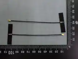
1/2λ dipole type
+1.9dBi
FCC INTEGRATION INSTRUCTIONS
No.
Item
Details
1
List of applicable FCC rules
FCC Part15.247
(2400-2483.5MHz, Frequency hopping systems)
2
Summarize the specific
operational use conditions
Only the antennas listed in the table on the previous page may be
used.
3
Limited module procedures
Not applicable.
4
Trace antenna designs
Not applicable.
5
RF exposure considerations
・This equipment complies with FCC radiation exposure limits set
forth for an uncontrolled environment.
i. When used in stationary receivers,
This equipment should be installed and operated with
minimum distance 20cm between the radiator & your
body.
ii. When used in remote control devices,
This transmitter must not be co-located or operating
in conjunction with any other antenna or
transmitter.
・Please include the above statement in the end user product manual.
6
Antennas
Only the antennas listed in the table on the previous page may be
used.
7
Label and compliance
information
The final end product must be labeled in a visible area with the
following: “Contains FCC ID: AZP-FEX12T”. The grantee's FCC ID can
be used only when all FCC compliance requirements are met.
8
Information on test modes
and additional testing
requirements
Since documents related to test modes and test procedures contain
our confidential information, please contact us at the address below.
FUTABA Corporation of America
Customer Service Desk
service@futabaUSA.com
9
Additional testing, Part 15
Subpart B disclaimer
The final host product still requires Part 15 Subpart B compliance
testing with the modular transmitter installed.6
10
Note EMI Considerations
Note that a host manufacture is recommended RF design engineering
testing and evaluation in case non-linear interactions generate
additional non-compliant limits due to module placement to host
components or properties.
11
How to make changes
If a permissive change, such as the addition of an antenna, is
required, please contact us at the address below.
FUTABA Corporation of America
Customer Service Desk
service@futabaUSA.com
Please note that we may not be able to accommodate your request
depending on the nature of the inquiry.
ISED Warning
This device contains licence-exempt transmitter(s)/receiver(s) that comply with Innovation,
Science and Economic Development Canada’s licence-exempt RSS(s). Operation is subject
to the following two conditions:
(1) This device may not cause interference.
(2) This device must accept any interference, including interference that may cause
undesired operation of the device.
This equipment complies with ISED radiation exposure limits set forth for an uncontrolled
environment.
i. When used in stationary receivers,
This equipment should be installed and operated with minimum distance 20cm
between the radiator & your body.
ii. When used in remote control devices,
This transmitter must not be co-located or operating in conjunction with any
other antenna or transmitter.
French:
Cet appareil radio est conforme au CNR-210 d’Industrie Canada. L’utilisation de ce dispositif
est autorisée seulement aux deux conditions suivantes : (1) il ne doit pas produire de
brouillage, et (2) l’utilisateur du dispositif doit être prêt à accepter tout brouillage
radioélectrique reçu, même si ce brouillage est susceptible de compromettre le
fonctionnement du dispositif.
Cet équipement est conforme aux limites d’exposition aux rayonnements IC établies pour un
environnement non contrôlé.
i. Lorsqu’il est utilisé dans des récepteurs fixes,
Cet équipement doit être installé et utilisé avec une distance minimale de 20 cm entre
la source de rayonnement et votre corps.
ii. Lorsqu’il est utilisé dans des dispositifs de télécommande,
Ce transmetteur ne doit pas être installé ou utilisé en association avec une autre
antenne ou un autre transmetteur.
This radio transmitter [IC:2914D-FEX12T] has been approved by Innovation, Science and
Economic Development Canada to operate with the antenna types listed below, with the
maximum permissible gain indicated. Antenna types not included in this list that have a gain
greater than the maximum gain indicated for any type listed are strictly prohibited for use
with this device.
No.
Parts Code
Model
Manufacturer
Type
Max. Gain
1
9M99Z15001
STDANTEMD-013
Sansei
1/2λ dipole type
+1.9dBi
The final end product must be labeled in a visible area with the following: “contains IC:
2914D-FEX12T”. The grantee's IC ID can be used only when all ISED compliance
requirements are met.

FCC Notice
This device complies with part 15 of the FCC rules. Operation is subject to the following two
conditions: (1) This device may not cause harmful interference, and (2) this device must
accept any interference received, including interference that may cause undesired operation.
This equipment has been tested and found to comply with the limits for a Class A digital
device, pursuant to part 15 of the FCC Rules. These limits are designed to provide reasonable
protection against harmful interference when the equipment is operated in a commercial
environment. This equipment generates, uses, and can radiate radio frequency energy and, if
not installed and used in accordance with the instruction manual, may cause harmful
interference to radio communications. Operation of this equipment in a residential area is
likely to cause harmful interference in which case the user will be required to correct the
interference at his own expense.
Any unauthorized changes or modifications to this device not expressly approved by Futaba
Corporation could void the user’s authority to operate the device and possibly result in
damage to the equipment and/or cause serious or fatal injuries to the operator or nearby
personnel.
This device is intended to be installed and used in accordance with the instructions contained
in this manual. Failure to comply with these instructions could void the user’s authority to
operate the device and possibly result in damage to the equipment and/or cause serious or
fatal injuries to the operator or nearby personnel.

Limited Warranty
FUTABA WARRANTS ONLY THAT THE INDUSTRIAL RADIO CONTROL SYSTEM GOODS OR PRODUCTS
FURNISHED HEREWITH SHALL BE FREE FROM DEFECTS IN MATERIAL AND WORKMANSHIP UNDER
NORMAL CONDITIONS OF USE AND SERVICE FOR A PERIOD OF ONE (1) YEAR FROM THE DATE OF SALE
TO THE PURCHASER WHO IS THE FIRST BUYER OF THE GOODS FOR USE OR CONSUMPTION AND NOT
FOR RESALE OTHER THAN AS A COMPONENT OF ANOTHER PRODUCT MANUFACTURED FOR SALE BY
SUCH PURCHASER (“CONSUMER”). FUTABA’S LIABILITY, WHETHER BASED ON BREACH OF WARRANTY
OR NEGLIGENCE, SHALL BE LIMITED, AT FUTABA’S ELECTION, TO REPLACEMENT OR REPAIR OF ANY
SUCH NONCONFORMING GOODS, F.O.B. FUTABA’S U.S.A. PLANT, OR, AT FUTABA’S ELECTION, CREDIT
FOR THE NET PURCHASE PRICE OF SUCH GOODS. ALL CLAIMS HEREUNDER MUST BE MADE IN WRITING
DURING THE WARRANTY PERIOD, AND FUTABA SHALL HAVE THE RIGHT PRIOR TO ANY RETURN OF
GOODS TO INSPECT ANY GOODS CLAIMED TO BE NONCONFORMING, AND IN ANY EVENT RESERVES THE
RIGHT TO REJECT CLAIMS NOT COVERED BY WARRANTY. THIS LIMITED WARRANTY CONSTITUTES
FUTABA’S SOLE WARRANTY. FUTABA MAKES NO OTHER WARRANTY OF ANY KIND, EXPRESS OR
IMPLIED, AND EXPRESSLY DISCLAIMS ANY IMPLIED WARRANTY OF MERCHANTABILITY OR
FITNESS FOR A PARTICULAR PURPOSE. FUTABA’S WARRANTY SHALL NOT APPLY IF, AMONG OTHER
LIMITATIONS CONTAINED HEREIN OR FURNISHED WITH THE PRODUCT, BUYER, OR CONSUMER, OR ANY
USER OF THE PRODUCT (A) ALTERS SUCH PRODUCT, OR (B) REPLACES ANY PART OF SUCH PRODUCT
WITH ANY PART OR PARTS NOT FURNISHED BY FUTABA FOR THAT PURPOSE, OR IF, AMONG SUCH
OTHER LIMITATIONS, PRODUCT FAILS TO OPERATE PROPERLY OR IS DAMAGED DUE TO ATTACHMENTS
OR COMPONENTS THAT ARE NOT FURNISHED BY FUTABA FOR USE WITH OR REPAIR OF THE PRODUCT
UNLESS SUCH USE IS AUTHORIZED IN WRITING IN ADVANCE BY FUTABA.
THIS LIMITED WARRANTY EXTENDS ONLY TO THE CONSUMER AND IS NOT ASSIGNABLE OR
TRANSFERABLE. This limited warranty shall not apply to fuses, lamps, batteries, or other items that are expendable by
nature, unless otherwise expressly provided.
This limited warranty does not cover any defect or damage to any of the goods caused by or attributable to force, accident,
misuse, abuse, faulty installation, improper maintenance, improper electrical current, failure to install or operate in
accordance with Futaba’s written instructions, repair or alteration by unauthorized persons, or leaking batteries. THE
GOODS ARE SENSITIVE ELECTRONIC DEVICES REQUIRING SPECIAL HANDLING, AND THIS LIMITED
WARRANTY DOES NOT APPLY TO PRODUCTS NOT HANDLED IN ACCORDANCE WITH INSTRUCTIONS
SET FORTH IN THE MANUAL.
THIS LIMITED WARRANTY DOES NOT COVER INDUSTRIAL RADIO CONTROL PRODUCTS
PURCHASED OR USED OUTSIDE OF THE UNITED STATES WITHOUT FUTABA’S PRIOR APPROVAL.
Returns
Futaba’s authorization must be obtained prior to return of any item for warranty or other repair or replacement or credit and
will reflect Futaba’s warranty service procedure. Consumer’s warranty rights are governed by the terms of Futaba’s Limited
Warranty, as above described. Products returned for warranty repair or replacement or credit must be carefully and securely
packed for return, preferably in the original carton or equivalent. The Consumer must also include in the carton a legible
copy of the bill of sale or invoice which shows the date of sale and the original Buyer’s and Consumer’s names, and also a
letter which gives the Consumer’s return address and contact telephone number, the model and serial numbers of the
product(s) returned, and a brief explanation of the problem or claimed defect. Any returned products that are replaced by
Futaba shall become the property of Futaba. If after inspection Futaba determines the defect is not covered by its limited
warranty, Futaba will notify Consumer of its determination and will not undertake any repairs or product replacement until
Consumer agrees to pay for all necessary parts and materials, labor (to be charged at Futaba’s standard repair rate then in
effect), and other expenses including all shipping charges and insurance. Futaba reserves the right to retain possession of
any product returned by Consumer because of defects not covered by Futaba’s warranty until Futaba receives Consumer’s
agreement as above noted or, if Consumer wants the product returned without repair or replacement, Consumer reimburses
Futaba for all shipping and handling charges incurred by Futaba. Issuance of credit for returned items shall be made at
Futaba’s unfettered discretion. Consumer will not be entitled to return defective goods for cash refunds. Consumer must
inspect goods immediately and no rejection or revocation of acceptance shall be permitted more than ten (10) days after
delivery to, or first use by, Consumer of the goods, whichever occurs first.

Patents – Copyrights – Trademarks – Proprietary Rights
If this product was manufactured according to designs or processes specified by Consumer, Consumer shall indemnify and
save Futaba, its affiliates, officers, agents, and employees, harmless from any expense, loss, attorneys’ fees, costs, damages,
or liability which may be incurred as a result of actual or alleged infringement of patent, copyright, or trademark rights.
Furnishing of these products does not convey a license, implied or otherwise, under any patent, copyright, or trademark
right in which Futaba has an interest, nor does it convey rights to trade secrets or any other proprietary information of
Futaba.
Limitation of Damages and Action
IN NO EVENT SHALL FUTABA BE LIABLE TO CONSUMER, OR ANY OTHER PERSON FOR ANY
INCIDENTAL, CONSEQUENTIAL, OR SPECIAL DAMAGES RESULTING FROM THE USE OF OR
INABILITY TO USE THIS PRODUCT, WHETHER ARISING FROM BREACH OF WARRANTY OR
NEGLIGENCE OF FUTABA, OR OTHERWISE. Any action hereunder must be commenced within one (1) year of
accrual of cause of action or be barred and forever waived. No modification or alteration of Futaba’s Limited Warranty or
any other provision of this paragraph or the above paragraphs shall result from Futaba’s acknowledgment of any purchase
order, shipment of goods, or other affirmative action by Futaba toward performance following receipt of any purchase order,
shipping order, or other form containing provisions, terms, or conditions in addition to or in conflict or inconsistent with any
such provisions.

1M36Q147-01
8
FCC Notice.................................................................................. v
Limited Warranty ............................................................................ v
Returns ................................................................................... vi
Patents – Copyrights – Trademarks – Proprietary Rights .................................... vii
Limitation of Damages and Action .......................................................... vii
1 Overview ................................................................................ 9
2 General Specification ................................................................... 9
2.1 High-frequency portion ................................................................ 9
2.2 External interface .................................................................... 9
2.3 Power supply ......................................................................... 10
2.4 Environmental specifications ......................................................... 10
2.5 Others ............................................................................... 10
2.6 External Terminal .................................................................... 11
2.7 Reset terminal ....................................................................... 12
2.8 Initialization time .................................................................. 12
2.9 Appearance ........................................................................... 12
3 Communication Method ................................................................... 13
3.1 Frequency hopping .................................................................... 13
3.2 Synchronization ...................................................................... 13
4 Communication procedure ................................................................ 14
4.1 Overview ............................................................................. 14
4.2 Send command ......................................................................... 14
4.3 Received data ........................................................................ 14
4.4 Master communication procedure ....................................................... 15
4.5 Slave communication procedure ........................................................ 15
4.6 Communication time ................................................................... 15
5 Other functions ........................................................................ 16
5.1 ID Registration ...................................................................... 16
6 Commands ............................................................................... 17
6.1 List of commands ..................................................................... 17
6.2 How to use commands .................................................................. 17
6.3 Command responses .................................................................... 17
6.3.1 Types of command responses ....................................................... 17
6.4 Details of the command functions ..................................................... 18
7 Memory register ........................................................................ 23
7.1 Memory register list ................................................................. 23
7.2 Memory register function detail ...................................................... 24
1M36Q147-01
9
1 Overview
(1) 2.4 GHz band FH (frequency hopping) type wireless module.
(2) This module has adopted a communication protocol that is intended to be used as a wireless
controller.
(3) Using the UART, it is set by the command input, and performs input and output operational data.
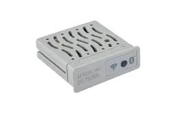
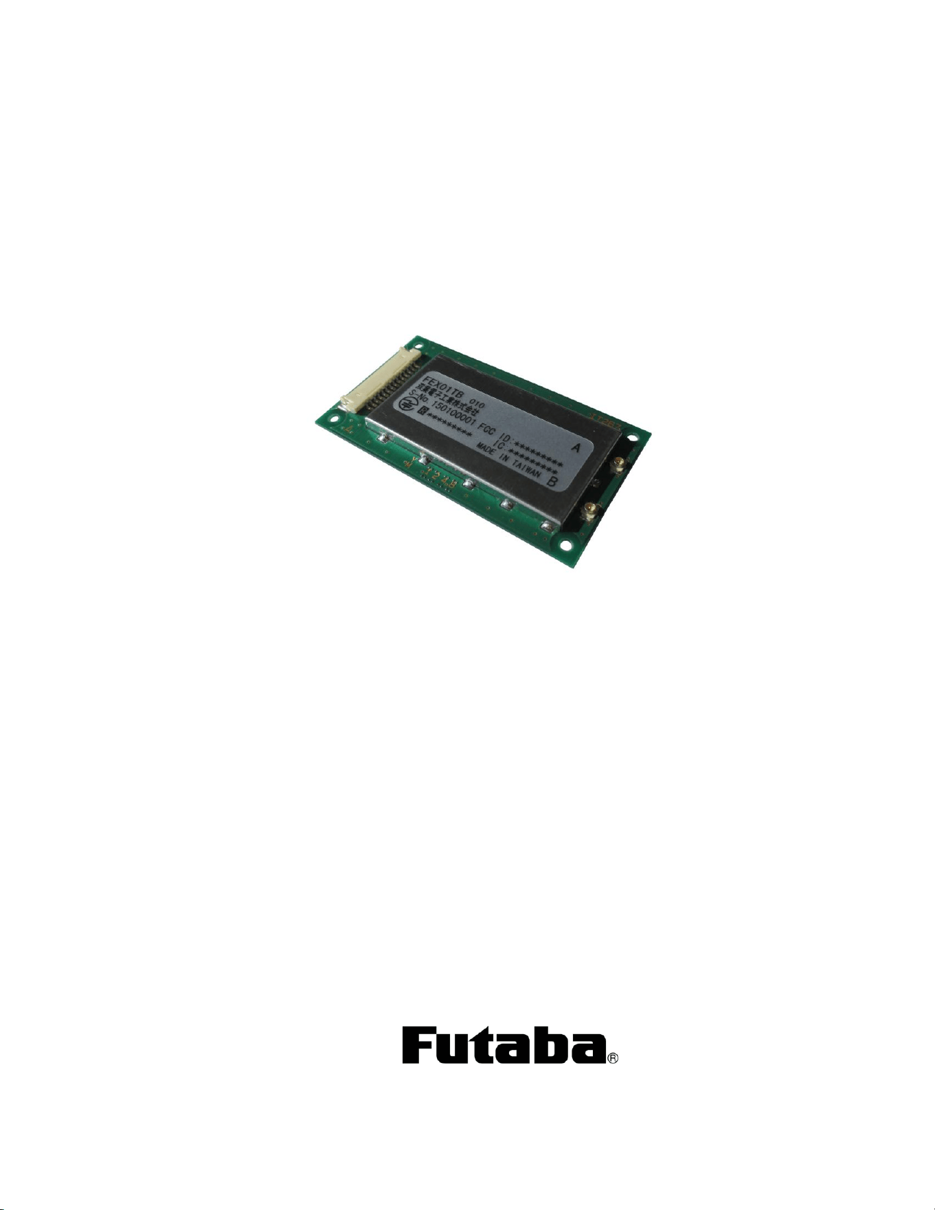
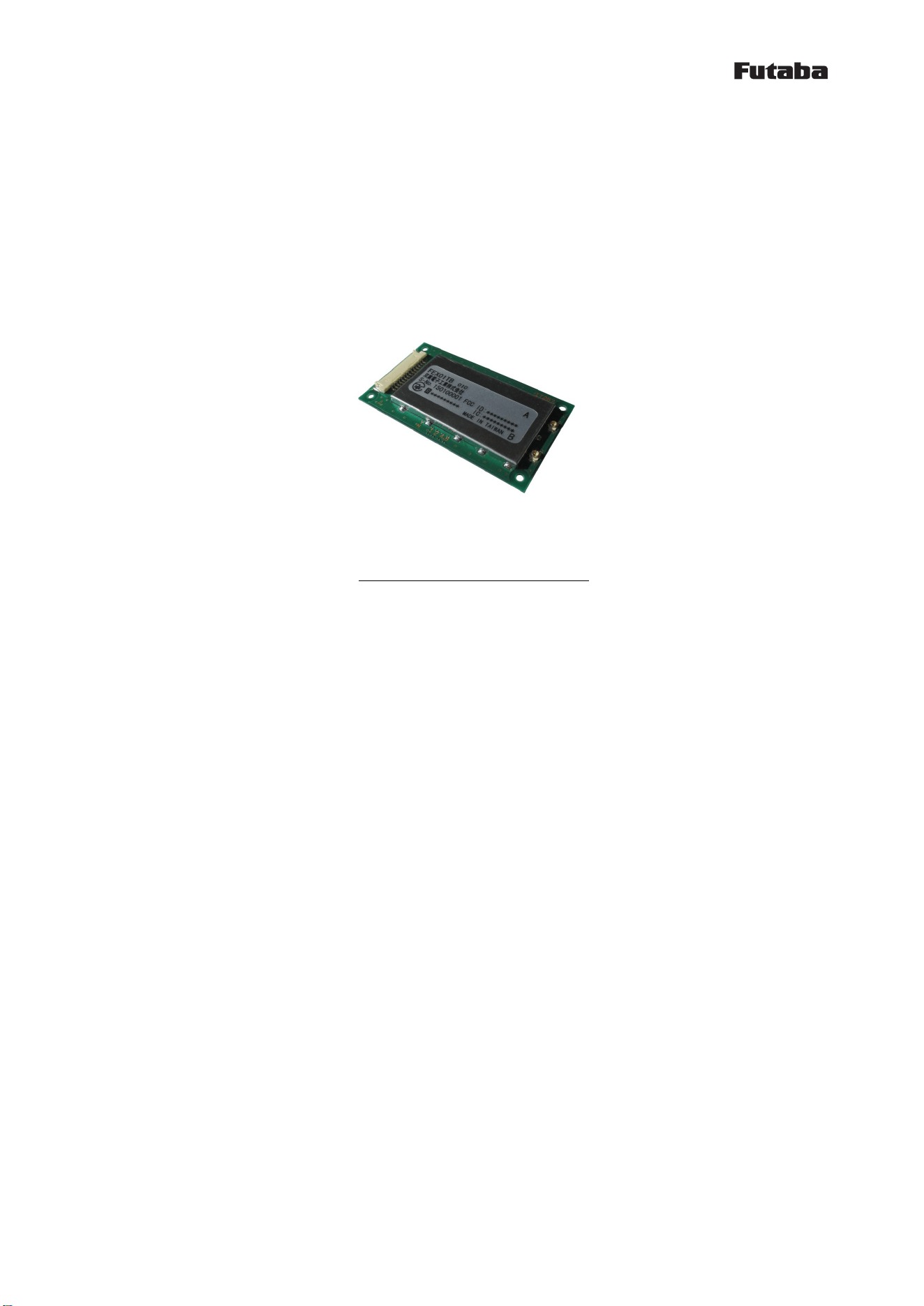
Table 1:FEX12TB Appearance photo
2 General Specification
2.1 High-frequency portion
・Technical standards :ARIB STD-T66 (Japan)
FCC Part15.247 (U.S.A.)
ISED RS-210 (Canada)
・Output power :15.0±2dBm (FEX12TB)
・Communication method :Spread spectrum FH system
・Spread bandwidth :60MHz
・Radio frequency band :2407.5MHz~2467.5MHz
・Frequency control :frequency hopping (31 patterns, 31 waves)
・Data modulation rate :128.143kbps
・Coverage area :outdoors 365m
(according to an external antenna, sight distance, and our measurement method)
・Antenna terminal :U.FL connector
・Antenna :diversity (Tx/Rx)
・Error detection function :CRC-CCITT(16bits)
2.2 External interface
・Physical interface :JAM SYB10-15WH (15pin)
Mating connector 51146-1400
・Interface :RS-232C(DCE-mode)
input 3.3V CMOS-level(with hysteresis)
output 3.3V CMOS-level
・Communication method : full duplex
・Synchronization method : start-stop synchronization method

1M36Q147-01
10
・Baud rate :9600/19200bps
・Flow control :none
・Data length :7 bit/8 bit
・Stop bit :1 bit/2 bit
・Parity :even/odd/none
2.3 Power supply
・Source voltage :DC 5V
・Consumption current :transmission 300mA or less
reception 35mA or less
average at communication 50 mA or less
2.4 Environmental specifications
・Temperature conditions :Operating temperature limits
ambient temperature;-20 to +70℃
Storage temperature range
ambient temperature;-30 to +70℃
・Operating humidity limits :90%RH or less (no condensing)
・Storage humidity range :90%RH or less (no condensing)
・Anti-vibration :50m/s
2
(JIS-C-60068-2-6)
・Anti-shock :500m/s
2
(JIS-C-60068-2-27)
2.5 Others
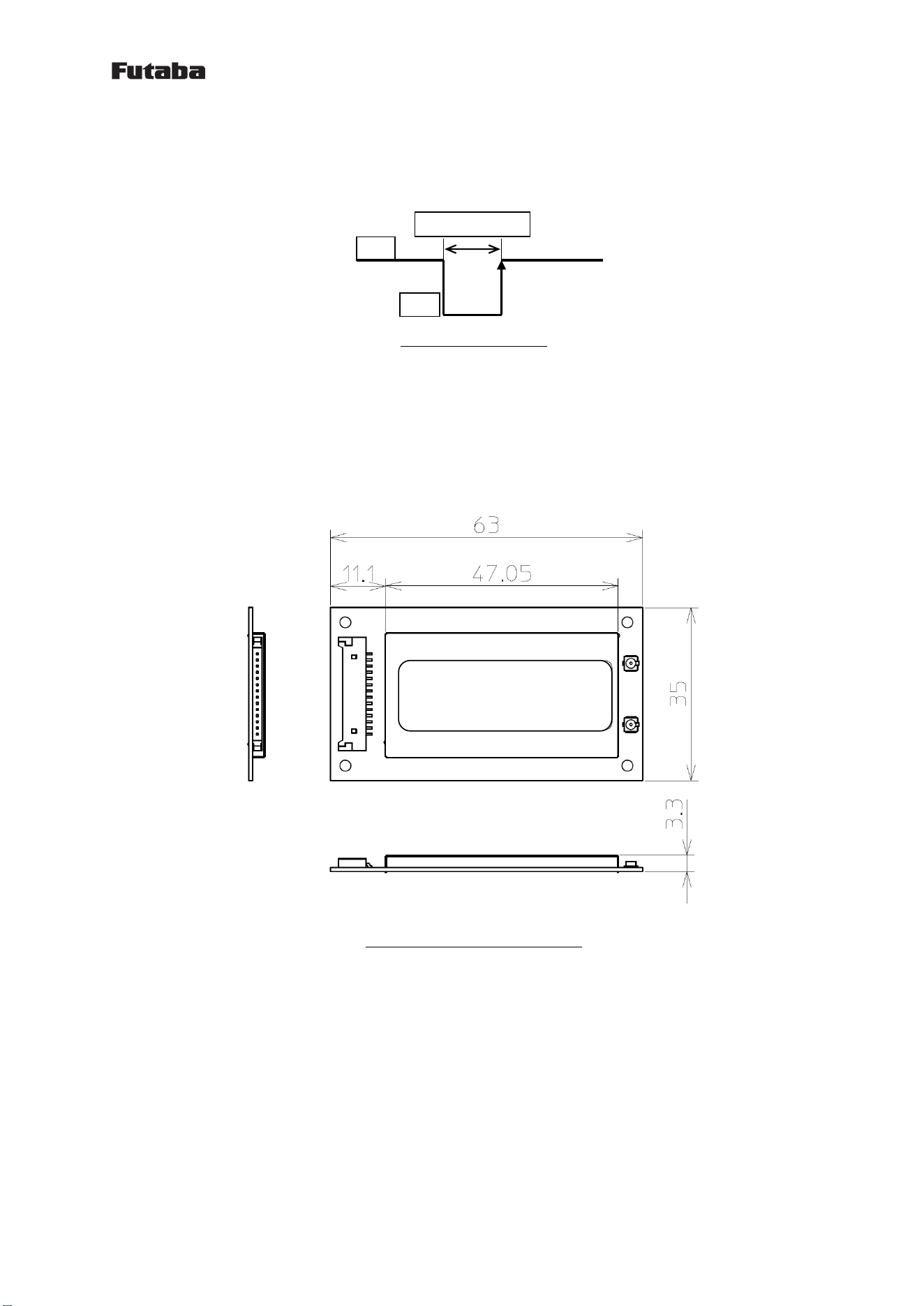
・External dimensions :63(W)×35(D)×3(H) mm
・Weight :about 14g
1M36Q147-01
11
2.6 External Terminal
Table 1:Terminal function
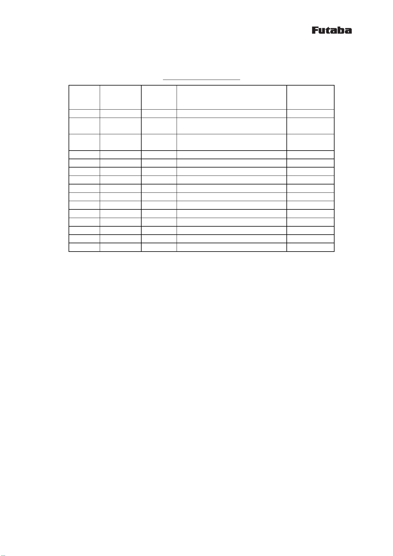
No.
Terminal
name
I/O
Function
Internal
terminal
processing
1
NC
-
2
RxD
OUT
UART RxD
(Response Output)
3
TxD
IN
UART TxD
(Command Input)
4
NC
-
5
GND
-
signal ground
6
CLK
IN
reserved
Pull-down
7
STE
IN
reserved
Pull-down
8
SDA
IN
reserved
Pull-down
9
SCL
IN
Reserved
Pull-down
10
VCC
-
Power DC 5V
11
RST
IN
CPU reset
12
3.3V
OUT
Test
13
Reserved
OUT
Reserved
Low
14
TEST
IN
Test
15
None
-
-
1M36Q147-01
12
2.7 Reset terminal
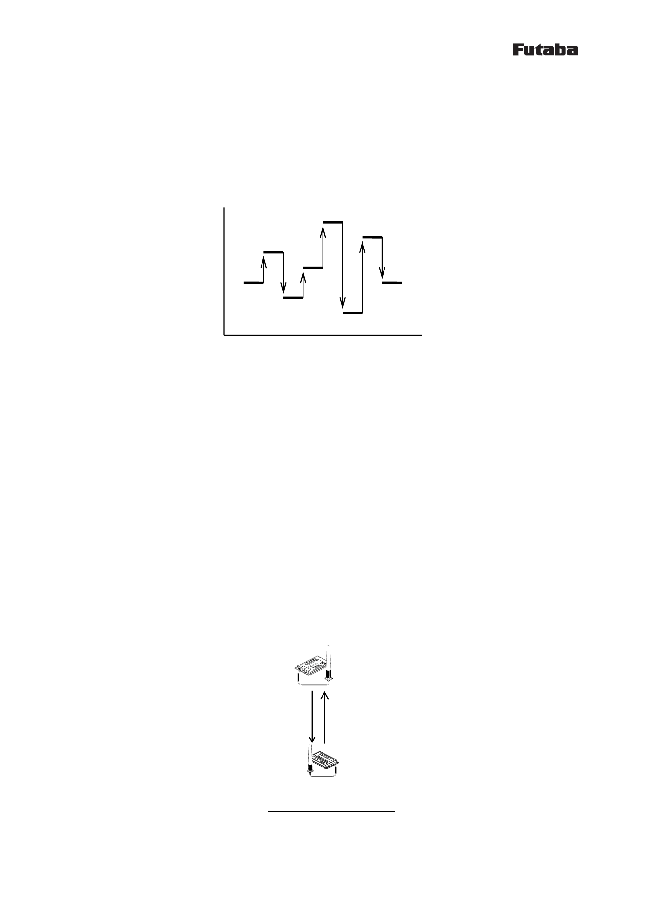
Resetting with the Reset terminal provides the pulse below.
Figure 2:Reset pulse
2.8 Initialization time
(1) The initialization time (after power up until accept command) is 90ms or less.
(2) The initialization time by the RST command input is 1200ms.
2.9 Appearance
Figure 3:FEX12TB External view
Minimus 1ms
High
Low
1M36Q147-01
13
3 Communication Method
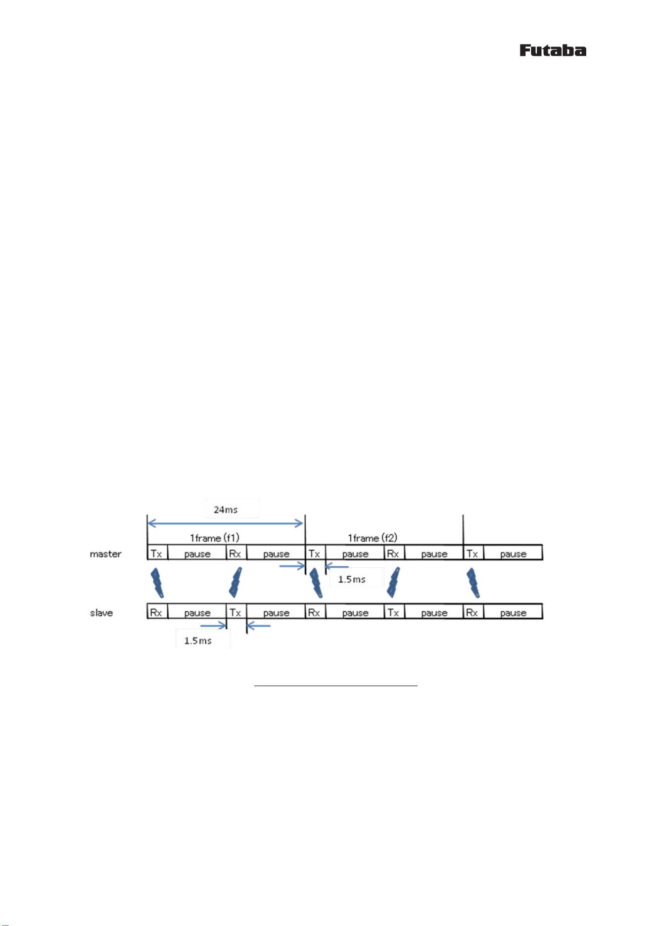
3.1 Frequency hopping
This wireless module employs an FH system as a diffusion method. In the FH system, diffusion signals
with a wide bandwidth are produced by hopping the frequency according to a certain pattern. The
pattern is called a frequency hopping pattern. This device has 31 types of frequency hopping patterns.
The same hopping pattern is set for the wireless machines that are intended to mutually communicate.
figure 4:frequency hopping
Even when the hopping pattern is the same, mutual communication is impossible when a wireless
module randomly hops the frequency. Therefore, in the frequency hopping system, one of the wireless
machines works as a standard, while other wireless machines synchronize the frequency and hopping
timing of each machine by receiving packets from the standard machine. This is called
synchronization.
3.2 Synchronization
The slave switches frequency while waiting for a wireless packet from the master. When a wireless
packet is received, it switches to the next frequency and waits for a wireless packet again. When
received, it is judged that the synchronization with the master was successful. After that, the
slave matches the timing and sends wireless packets to the master.
No timeout is set, even for cases when synchronization is unsuccessful due to a poor communication
environment. It continues receiving until synchronization succeeds. In the case when
synchronization fails during communication for some reason, a maximum of 1000ms is required to
re-synchronize.
figure 5:master and slave
frequency
time
master(transmitter)
slave(receiver)

1M36Q147-01
14
4 Communication procedure
4.1 Overview
Communication is done in the following manner:
(1) Right after the power is turned on, the master and slave does not have wireless communication
and is in an invalid state.
(2) For sending/receiving a wireless packet, start the FH operation by inputting the @FHS command
(the master and the slave).
The master initiates RF transmission and reception.
The slave starts RF reception, wait for communication from the master.
(3) If FH synchronization acquisition, slave start also sent. After that, the slave will continue
in automatic synchronization.
(4) By TLC command to set the data you want to send.
(5) In FH synchronization acquisition, it will receive the data periodically from the
communication partner.
If the synchronization is out, it does not receive the data.
(6) To stop sending/receiving a wireless packet, type the @FHE command and quit the FH operation.
4.2 Send command
The command header is "@TLC", the terminator is CR+LF (0x0D 0x0A). There is no response to the
command.
Please send data as a binary data of 14-byte fixed.
Radio transmission will be run every 24ms. By @TLC command, it will update the transmitted data.
If @TLC command is not inputted, the previous data is wirelessly transmitted. If you also send
command has not been entered once, the data of all 0 is wireless transmitted.
【Send (update) format】
@TLC[Binary data 14 bytes][CRLF]
4.3 Received data
The received data is appended "RLC" of 3 bytes as a header.
The Received data is binary data of 14-byte fixed.
Radio reception will be run every 24ms. In a state that can't be wireless communication, it
will not be output to the wired.
【Reception format】Repeat
RXT[Binary data 14 bytes]
1M36Q147-01
15
4.4 Master communication procedure
(1) After the power is turned on, the master does not perform the wireless communication.
(2) If you want to transmit and receive wireless packet, enter FHS command.
(3) As long as the FH synchronization acquisition, the data from the slave is output to the wired.
The received data will be "RLC" header is added.
(4) If you send the data to the slave, enter the @TLC command. By sending @TLC command regularly,
the transmitted data is updated.
(5) If you stop the wireless communication, enter the @ FHE command.
4.5 Slave communication procedure
(1) After the power is turned on, the slave does not perform the wireless communication.
(2) If you want to transmit and receive wireless packet, enter FHS command.
(3) As long as the FH synchronization acquisition, data from the master is output to the wired.
The received data will be "RLC" header is added.
(4) If you send the data to the master, enter the @TLC command. By sending @TLC command regularly,
the transmitted data is updated.
(5) If you stop the wireless communication, enter the @ FHE command.
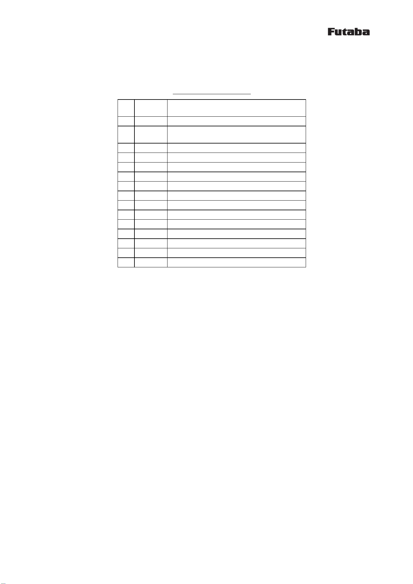
4.6 Communication time
Interval of the frequency hopping (switching frequency) is 24ms. This 24ms is one frame. The master
wirelessly transmits (1 packet transmission) at the beginning of the frame. Communication time
is about 1.5ms. The slave that is synchronized with the master wirelessly receives the packet at
the beginning of the frame.
The figure below shows the timing.
Figure 6:FH communication timing

1M36Q147-01
16
5 Other functions
5.1 ID Registration
In order to associate the master and the slave, an ID code is used. Each wireless module has
a unique value.
For wireless communication, registration of the ID code of the communication partner is necessary.
Wireless machines without ID code registration are unable to communicate. This prevents improper
connections.
To make the pairing, in a state in which the closer to the master / slave, and then run the @IDS
command to both the master / slave. In the case of slave, it is possible to register up to two.
Please refer to the description of @IDS command for how the second unit of the specified.
If the pairing is successfully complete, "Pair" response is output, pairing ID code is written
to the memory. In order to perform the normal communication, please do the once reset.
If the pairing is not completed, approximately becomes a time-out within 5 seconds, it is returned
N0 response.
The slave is possible to register the master up to two.
However, communication is carried out in a one-to-one, you will not be able to communicate from
two masters. The slave keeps a connection with the master that initiated the first communication.
1M36Q147-01
17
5.1.1
6 Commands
6.1 List of commands
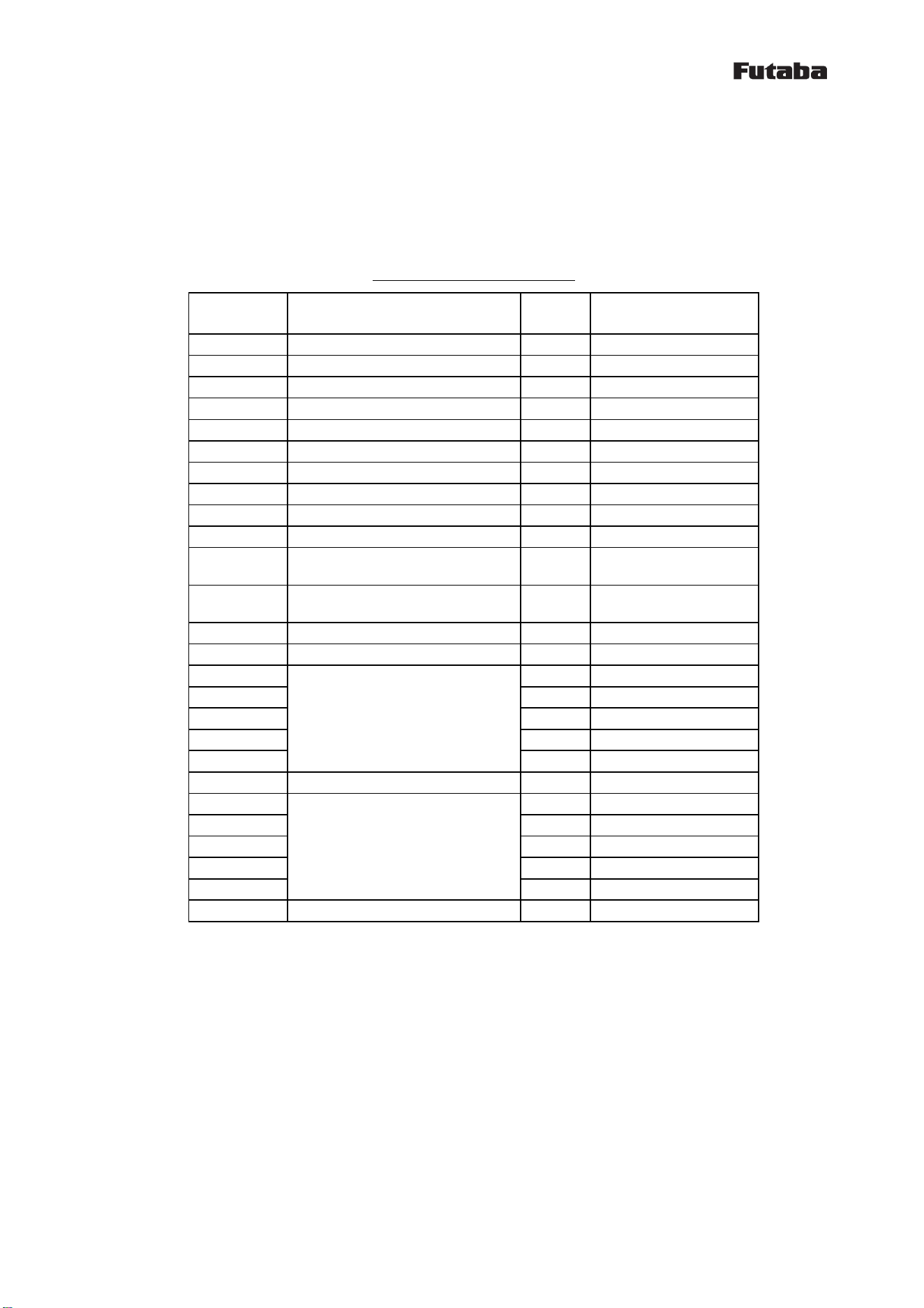
Table 2:List of commands
No.
Command
name
Function
1
ARG
Display all register values
2
DBM
Reference a reception intensity of received
packet
3
ERR
Reference error status
4
FHE
End FH operation
5
FHS
Start FH operation
6
ID1
Reference and set pairing ID1
7
ID2
Reference and set pairing ID2
8
IDS
Start ID registration
9
INI
Initialize register values
10
ODA
Disable output
11
OEN
Enable output
12
REG
Reference and set register values
13
RST
Reset
14
TLC
Set wireless data
15
VER
Display version
6.2 How to use commands
(1) When inputting a command to the wireless module, add 1 byte header for command recognition
(command header) at the beginning of the command, in order to differentiate from regular data.
The command header is “@” (40H).
(2) Command is case-sensitive.
(3) A 2-byte terminator is used to terminate a command. The terminator is [CRLF] (0DH: carriage
return + 0AH: line feed).
(4) The wireless module executes a command process after recognizing a command. For a command with
a response, it returns the response to external devices after the process is completed.
(5) Do not input subsequent commands or data before getting a response.
(6) Command example
@ARG[CRLF]
6.3 Command responses
6.3.1 Types of command responses
Command responses and their meanings are:
P0: normal termination
P1: running command
N0: command error
N6: memory register writing error

1M36Q147-01
18
6.4 Details of the command functions
The symbols used in this section have the following meaning:
[ ] : Required input parameter/s
( ) : Optional input parameter/s
ARG :Display all register values
【Format】
ARG
【Response】
Setting list display
N0 : command error
【Function】
・ Refers to all contents of memory register. Displays a two-digit hexadecimal number plus H at
the end.
DBM : Reference the reception intensity of received packet
【Format】
DBM
【Response】
-XXXdBm : reception intensity
N0 : command error
【Function】
・Reads the reception intensity of the most recent, correctly received packet, and displays it
in decibels.
・When none has been received after resetting, “-134dBm” is displayed.
・The signal strength indication is not absolute. It can be used for accurate relative measurements
but should not be considered an absolute value.
ERR :Reference error status
【Format】
ERR
【Response】
xxH :error status
N0 :command error
【Function】
・This command display the error information of the internal this module. If 00H is no error.
・bit2=1: memory (settings area) error
・bit1=1: memory (user area) error
・bit0=1: RF error

1M36Q147-01
19
FHE: End FH operation
【Format】
FHE
【Response】
P0 : normal termination
N0 : command error
【Function】
・End FH operation. At this status, wireless transmission does not occur.
・Master/Slave stops radio transmission and reception. If state that FH synchronization acquisition,
and then release it.
・Even when there is received data from a paired module, wired output does not occur.
FHS :Starts FH operation
【Format】
FHS
【Response】
P0 : normal termination
N0 : command error
【Function】
・Starts FH operation.
・Master/Slave starts radio transmission and reception.
・When there is received data from a paired master, wired output starts.
・If there is data received from pairing the communication partner, to start the output to the
wired.
ID1 :Reference and set pairing ID1
【Format】
ID2(:pairing ID code 1)
pairing ID code 1 : xxxxxxxxx(9-digit)
【Response】
xxxxxxxxx : pairing ID code 1 (when when referencing)
P0 : normal termination (when setting)
N0 : command error
【Function】
・References and sets the pairing ID code 1.
・By inputting only the command, currently set values can be referenced.
・Specify the ID code (9-digit Serial Number) of the module that is the communication partner.
・Both master and slave are valid.
・The setting becomes effective after a reset.

1M36Q147-01
20
ID2 :Reference and set pairing ID2
【Format】
ID2(:pairing ID code 2)
pairing ID code 2 : xxxxxxxxx(9-digit)
【Response】
xxxxxxxxx : pairing ID code 2 (when when referencing)
P0 : normal termination (when setting)
N0 : command error
【Function】
・References and sets the pairing ID code 2.
・By inputting only the command, currently set values can be referenced.
・Specify the ID code (9-digit Serial Number) of the module that is the communication partner.
・Slave only is valid.
・The setting becomes effective after a reset.
IDS :Start ID registration
【Format】
IDS:[pairing area]
pairing area : x (1= pairing ID code 1, 2= pairing ID code 2)
【Response】
P0 : normal termination
Pair : pairing is completed
N0 : command error, or pairing is not completed
N6 : memory register writing error
【Function】
・Starts pairing operation.
・In the case of master, please specify '1' to the pairing area.
・In the case of slave, please specify '1' or '2' to the pairing area.
INI : Initialize register value
【Format】
INI
【Response】
P0 : normal termination
N0 : command error
【Function】
・Resumes all contents of the memory register in the wireless module to the status at factory
shipment.

1M36Q147-01
21
ODA :Disable output
【Format】
ODA
【Response】
P0 :normal termination
N0 :command error
【Function】
・Disable the radio transmission and wired output. Temporarily used when you want to stop FH
communication. If this module already has FH synchronization acquisition, also it will continue
to maintain FH synchronization after executing this command.
・Output in the initial state is enabled.
・Slave only.
OEN :Enable output
【Format】
OEN
【Response】
P0 :normal termination
N0 :command error
【Function】
・Enable the radio transmission and wired output.
・Output in the initial state is enabled.
・Slave only.
REG :Reference and set register values
【Format】
REG[register number](:set value)
Register number : 00~XX
Set value : input a two-digit hexadecimal number with H at the end,
or a three-digit decimal number without any suffix.
【Response】
XXX : currently set value (when referencing)
P0 : normal termination (when setting)
N0 : command error
N6 : memory register writing error
【Function】
・References and sets the memory register.
・By inputting only a register number, currently set values can be referenced.
・The setting will be valid after reset.

1M36Q147-01
22
RST :Reset
【Format】
RST
【Response】
P0 : normal termination
N0 : command error
【Function】
・This module will be reset.
TLC :Set wireless data
【Format】
TLC[binary data]
Binary data : 14-bytes fixed
【Response】
None
【Function】
・It specifies the data you want to send to the communication partner. It is 14-bytes fixed in
binary data.
・In order to avoid the mixing of the received data, there is no response to this command.
・Input of this command, please as a 50ms interval at the shortest.
VER : Display version
【Format】
VER
【Response】
Program Version 1.000 : display version
N0 : command error
【Function】
・Reads a program version of the wireless module.
・X.XXX
Improvements and bug fixes within a range of specifications
Minor specification change
Major specification change
1M36Q147-01
23
7 Memory register
The memory register is a register that sets and memorizes operation modes and communication
parameters for the wireless module. These values are read when the power is turned ON, and the
module starts operating according to the setting.
7.1 Memory register list
Table 3:Memory register list
Register
number
Function
Default
Default function
REG00
Operation mode
00H
Master
REG01
Reserve
00H
REG02
Frequency hopping pattern
00H
REG03
Reserve
00H
REG04
Wireless communication setting 1
08H
Antenna diversity
REG05
Wireless communication setting 2
00H
REG06
Reserve
00H
REG07
Reserve
00H
REG08
Wired communication setting 1
01H
115200bps
REG09
Wired communication setting 2
00H
REG10
FH synchronization determination
setting 1
00H
REG11
FH synchronization determination
setting 2
00H
REG12
Detailed setting
08H
REG13
Reserve
00H
REG14
Pairing ID code 1
00H
REG15
00H
REG16
00H
REG17
00H
REG18
00H
REG19
Reserve
00H
REG20
Pairing ID code 2
00H
REG21
00H
REG22
00H
REG23
00H
REG24
00H
REG25
Reserve
00H
1M36Q147-01
24
7.2 Memory register function detail
REG00:Operation mode [default:00H]
* Sets an operation mode (for the master or the slave).
Table 4:Operation mode
00H
Master (default)
01H
Slave
REG01:Reserved [default:00H]
* Not used in this wireless module. Leave default setting.
REG02:Frequency hopping pattern [default:00H]
* Sets the frequency hopping pattern. It can be set to 00~1E (0~30).
* Master only settings are valid. Slave sets the frequency hopping pattern automatically based
on the information of the master.
* In the initial state, a specific frequency hopping pattern is set. Because it is set to 00H
if you initialize, please set again.
* When using multiple systems within the same area, the frequency may periodically match and
interfere with each other even when the frequency hopping patterns are different.
REG03:Reserved [default:00H]
* Not used in this wireless module. Leave default setting.
REG04:Wireless communication setting 1 [default:08H]
Bit7~4:Reserved
* Not used in this machine. Make sure to set to 0.
Bit3:Antenna diversity
Table 5:Antenna diversity
0
Disable antenna diversity
1
Enable antenna diversity (default)
* Enables/disables antenna diversity.
* When used with two antennas, set to 1 in this bit.
Bit2:Antenna selection
Table 6:Antenna selection
0
Antenna is fixed to A (default)
1
Antenna is fixed to B
* At the non-diversity reception, decide the antenna terminal.
1M36Q147-01
25
Bit1~0:Reserved
* Not used in this machine. Make sure to set to 0.
REG05:Wireless communication setting 2 [default:00H]
* Not used in this wireless module. Leave default setting.
REG06:Reserved [default:00H]
* Not used in this wireless module. Leave default setting.
REG07:Reserved [default:00H]
* Not used in this wireless module. Leave default setting.
REG08:Wired communication setting 1 [default:01H]
Bit 7: data length
Table 7: Data length
0
8 bit data (default)
1
7 bit data
Bit 6: parity bit
Table 8: Parity bit
0
Without parity (default)
1
With parity
Bit 5: Even/odd parity
Table 9: Parity
0
Even parity (default)
1
Odd parity
* Invalid when “without parity” is set in bit 6.
Bit4: Stop bit
Table 10: Stop bit
0
1 stop bit (default)
1
2 stop bit
Bit3:Reserved
* Not used in this machine. Make sure to set to 0.
1M36Q147-01
26
Bit2~0:Baud rate setting
Table 11:Baud rate
Bit2
Bit1
Bit0
Baud rate
0
0
0
19200bps
0
0
1
115200bps
(default)
0
1
0
Reserved
0
1
1
Reserved
1
0
0
Reserved
1
0
1
Reserved
1
1
0
Reserved
1
1
1
Reserved
REG09:Wired communication setting 2 [default:00H]
Bit7~5:Reserved
* Not used in this machine. Make sure to set to 0.
Bit4:Addition and deletion of CRLF
Table 12:Addition and deletion of CRLF
0
Do not add the CR+LF code to the receive data. (default)
1
Add the CR+LF code to the receive data.
* Sets whether adding the CRLF code or not to the received data.
Bit3~0:Reserved
* Not used in this machine. Make sure to set to 0.
REG10~11:Reserved [default:00H]
* Not used in this wireless module. Leave default setting.
REG12:Detailed setting [default:08H]
Bit7:Startup message output
Table:Startup message output
0
Disable startup message output (default)
1
Enable startup message output
* When you want to output message at startup, set to 1 in this bit.
* At startup, “Input command” is output to the wired. By this message, you can recognize the
activation timing.
Bit6~4:Reserved
* Not used in this machine. Make sure to set to 0.
* No function assignment.
1M36Q147-01
27
Bit3:Receive level control
Table:Receive level control
0
Disable receive level control
1
Enable receive level control (default)
* When used with “Receive level control”, set to 1 in this bit.
* “Receive level control” turns LNA Off and decreases the reception level when communication
at the short distance.
Bit2~0:Reserved
* Not used in this machine. Make sure to set to 0.
* No function assignment.
REG13:Reserved [default:00H]
* Not used in this wireless module. Leave default setting.
REG14~18:Pairing ID code 1 [default:00H]
* Sets an ID code for a pairing machine.
* Both the master and slave use this.
REG19:Reserved [default:00H]
* Not used in this wireless module. Leave default setting.
REG20~24:Pairing ID code 2 [default:00H]
* Sets an ID code for a pairing machine.
* Only the slave use this.

1M36Q147-01
28
REG25:Reserved [default:00H]
* Not used in this wireless module. Leave default setting.