Installation
Guide
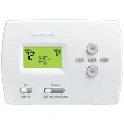
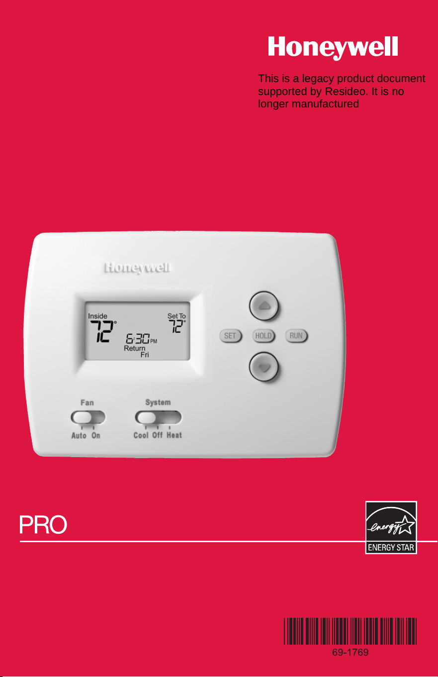
TH4110B
Programmable Thermostat
This is a legacy product document
supported by Resideo. It is no
longer manufactured

Product Application
This thermostat provides electronic control of 24 VAC single-stage heating and cool-
ing systems, or 750 mV heating systems.
System Types
• Gas, oil, or electric heat with air
conditioning
• Warm air, hot water, high-efficiency
furnaces, heat pumps, steam, gravity
• Heat only
• Heat only with fan
• Cool only
• 750 mV heating systems
Power Type
• AA alkaline batteries (2)
System Settings
• Heat, Off, Cool
Fan Settings
• Auto, On
Must be installed by a trained, experienced technician
• Read these instructions carefully. Failure to follow these instructions can dam-
age the product or cause a hazardous condition.
• Check the ratings in this booklet to verify that this product is suitable for your
application (see page 12).
• Always test for proper operation after installation (see pages 8-9).
CAUTION: ELECTRICAL HAZARD
Can cause electrical shock or equipment damage. Disconnect power before
beginning installation.
MERCURY NOTICE
If this product is replacing a control that contains mercury in a sealed tube, do not
place the old control in the trash. Contact your local waste management authority for
instructions regarding recycling and proper disposal.
® U.S. Registered Trademark. Patents pending.
Copyright © 2005 Honeywell International Inc. All rights reserved.
PRO TH4110B Programmable Thermostat
1
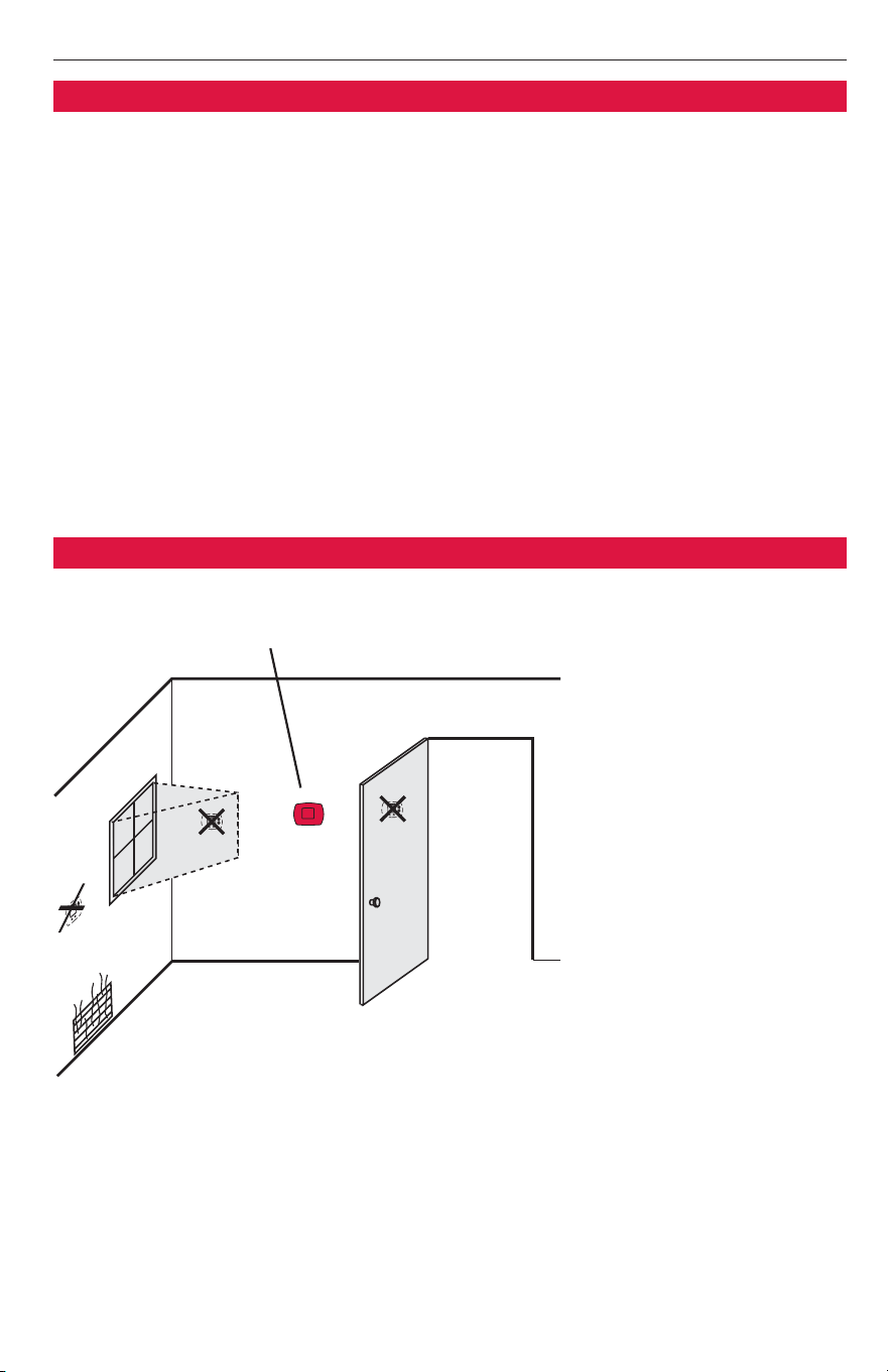
Install the thermostat about 5 feet (1.5m) above the floor in an area
with good air circulation at average temperature.
Do not install in locations where the thermostat can be affected by:
• Drafts or dead spots behind doors and in corners
• Hot or cold air from ducts
• Sunlight or radiant heat from appliances
• Concealed pipes or chimneys
• Unheated/uncooled areas such as an outside wall behind the thermostat
NO
NO
NO
IInnssttaallllaattiioonn
Pre-installation checklist ................2
Wallplate installation ......................3
Wiring..............................................4
Wiring diagrams ..............................5
IInnssttaalllleerr SSeettuupp
Fan operation settings ....................6
Battery installation ..........................7
Thermostat mounting ....................7
Installer setup..................................8
Installer system test ........................9
AAppppeennddiicceess
Quick reference to controls..........10
Quick reference to display............10
Compressor protection ................10
In case of difficulty ......................11
Accessories....................................12
Specifications ................................12
Table of contents
Installation tips
Installation Guide
2
Pre-installation checklist
Package contents
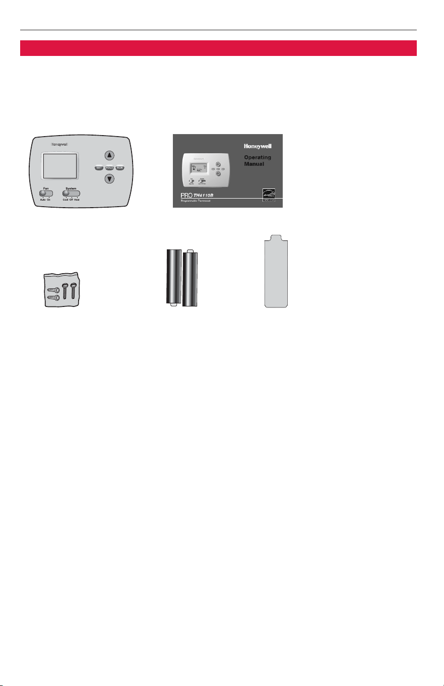
Check to make sure your package includes the following items:
Operating manual
Wall anchors and
mounting screws
(2 each)
AA alkaline
batteries (2)
Quick reference card
PRO TH4110B
digital thermostat
(wallplate attached to back)
Required tools & supplies
• No. 2 Phillips screwdriver
• Small pocket screwdriver
• Drill
• Drill bit (3/16” for drywall, 7/32” for plaster)
• Hammer
• Pencil
• Electrical tape
• Level (optional)
PRO TH4110B Programmable Thermostat
3
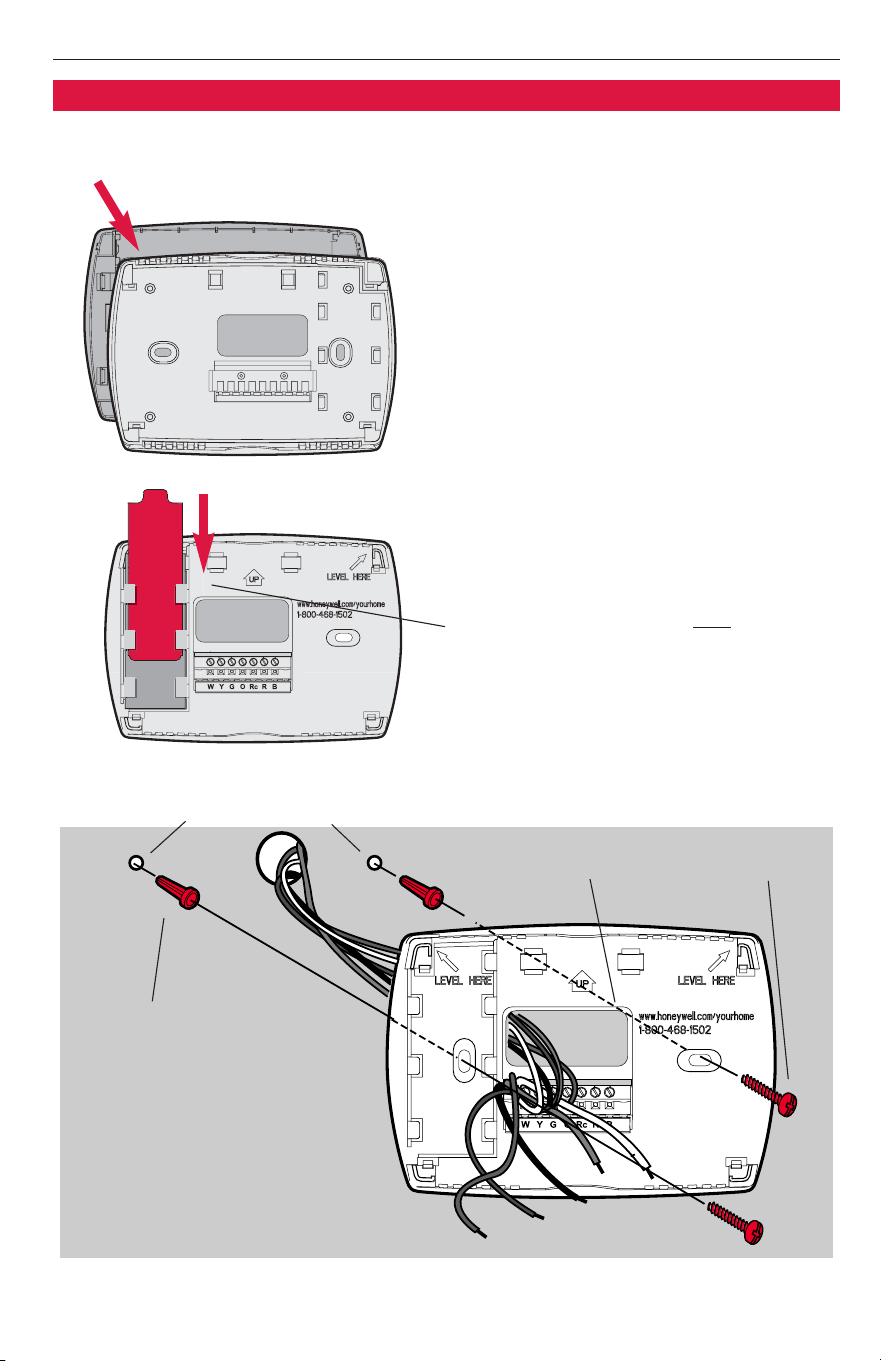
Remove the wallplate from the ther-
mostat as shown at left, then follow
directions below for mounting.
1 Pull wires through wire hole.
2 Position wallplate on wall, level and
mark hole positions with pencil.
3 Drill holes at marked positions as
shown below, then tap in supplied
wall anchors.
4 Place wallplate over anchors, insert
and tighten mounting screws.
5 Insert quick reference card in slot
in front of wall plate.
Grasp top and bottom of wallplate
and pull to remove from thermostat.
Drill 3/16” holes for drywall.
Drill 7/32” holes for plaster.
Wall anchors
Mounting screwsWire hole
Wallplate installation
Insert quick reference card after
wallplate is mounted (see mounting
instructions, below)
Installation Guide
4
Wiring
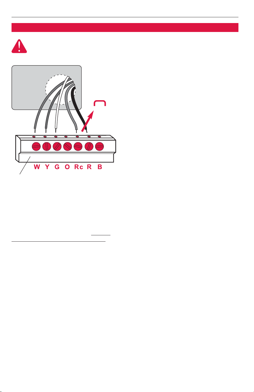
1 Loosen screw terminals, insert
wires into terminal block, then
re-tighten screws.
2 Push excess wire back into the
wall opening. Keep wires in shaded
area as shown at left.
3 Plug the wall opening with non-
flammable insulation to prevent
drafts from affecting thermostat
operation.
Terminal Designations
WW
Heat relay.
YY
Compressor contactor.
GG
Fan relay.
OO
Heat pump changeover valve
energized in cooling.
RRcc
Cooling power. Connect to
secondary side of cooling
system transformer.
RR
Heating power. Connect to
secondary side of heating
system transformer.
BB
Heat pump changeover valve
energized in heating.
Terminal
block
NOTES
R & Rc terminals
In single-transformer system, leave metal
jumper in place between R & Rc. Remove
metal jumper if two-transformer system
.
Heat pump systems
If wiring to a heat pump, use a small piece of
wire (not supplied) to connect terminals W
and Y.
Wire specifications
Use 18- to 22-gauge thermostat wire.
Shielded cable is not required.
Keep wires in this
shaded area
CAUTION: ELECTRICAL HAZARD. Can cause electrical shock or equipment damage.
Disconnect power before wiring.
Wiring
Jumper
PRO TH4110B Programmable Thermostat
5
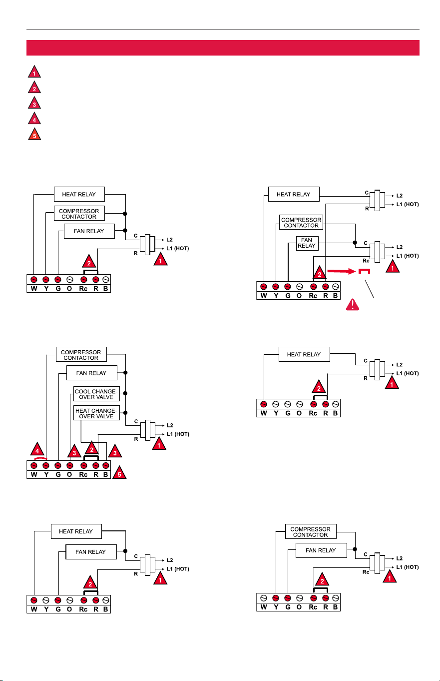
Typical 1H/1C system: 1 transformer Typical 1H/1C system: 2 transformers
Power supply. Provide disconnect means and overload protection as required.
Factory-installed jumper. Remove for 2-transformer systems only.
Use either O or B terminals for changeover valve.
Use a small piece of wire (not supplied) to connect W and Y terminals.
Set fan operation switch to Heat Pump (see page 6) and configure for heat pump (see pg. 8).
Remove jumper
Wiring diagrams
Typical 1H/1C heat pump system Typical heat-only system
Typical heat-only system with fan Typical cool-only system
Installation Guide
6
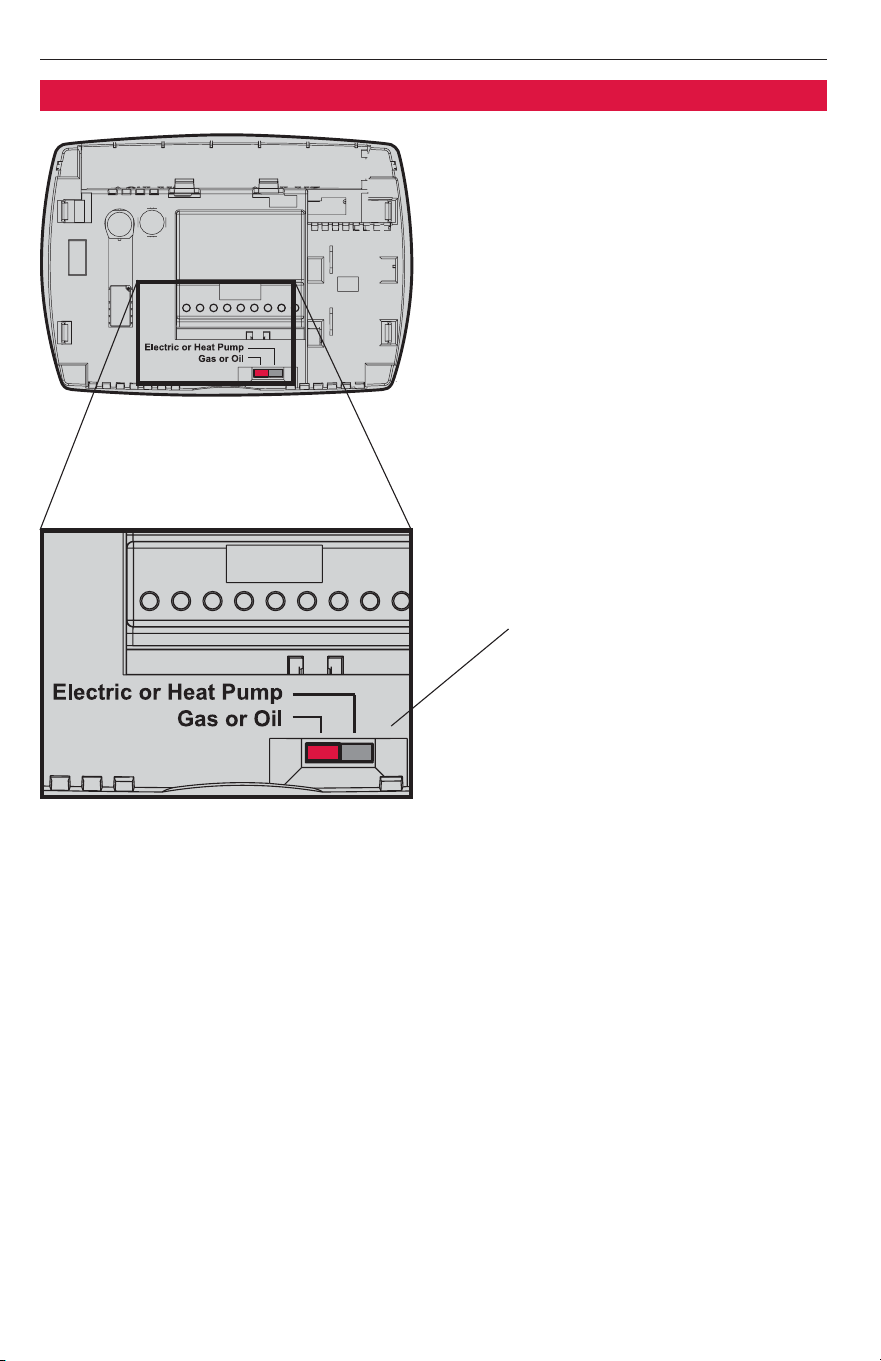
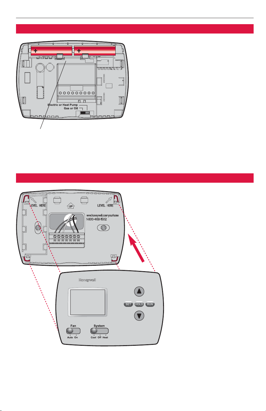
•
GGaass oorr OOiill::
For gas or oil heating
systems, leave the fan operation
switch in this factory-set position
(This setting is for systems that
control the fan in a call for heat.)
•
EElleeccttrriicc oorr HHeeaatt PPuummpp::
Change the
switch to this setting for heat
pump or electric heat systems.
(This setting is for systems that
allow the thermostat to control the
fan in a call for heat, if a fan wire is
connected to the
GG
terminal.)
Set fan operation switch
Fan operation settings
PRO TH4110B Programmable Thermostat
7
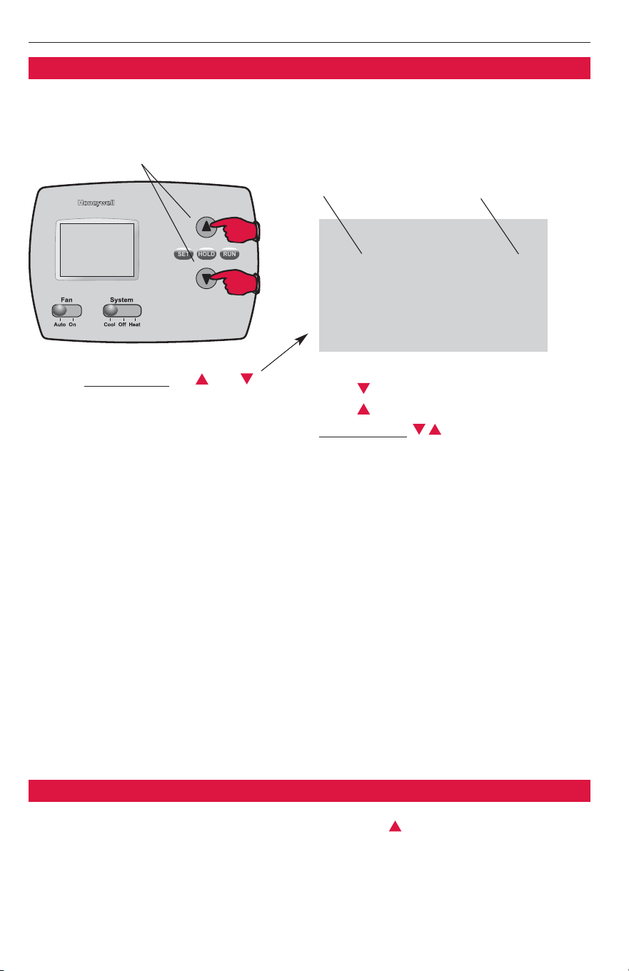
Install batteries in back of thermostat
Install two AA alkaline batteries in the
back of the thermostat, as shown at
left.
Fresh batteries should be installed
immediately when the
RREEPPLLAACCEE BBAATTTT
warning begins flashing (see page 10.)
The warning flashes about two months
before batteries are depleted.
Even if the warning does not appear,
Batteries should be replaced once a year,
or before the home is left vacant for
more than a month.
Battery installation
Align the 4 tabs on the wallplate with
corresponding slots on the back of the
thermostat, then push gently until the
thermostat snaps in place.
Thermostat mounting
Setup
1
0
Installation Guide
8
1
5
9
14
15
System type
Heating cycle rate
(CPH: cycles/hour)
Compressor
cycle rate (CPH)
Temperature
display
Compressor
protection
0 Gas, oil or electric heat with air conditioning
1 Heat pump (5 minute compressor off time in heating and cooling)
5 For gas or oil furnaces of less than 90% efficiency
1 For steam or gravity systems
3 For hot water systems & furnaces of over 90% efficiency
9 For electric furnaces
[Other cycle rate options: 2, 4, 6, 7, 8, 10, 11 or 12 CPH]
3 Recommended for most compressors
[Other cycle rate options: 1, 2, 4, 5 or 6 CPH]
0 Fahrenheit
1 Celsius
5 Five-minute compressor off time **See page 10
[Other options: 0, 1, 2, 3 or 4-minute off time]
Setup Function Settings & Options
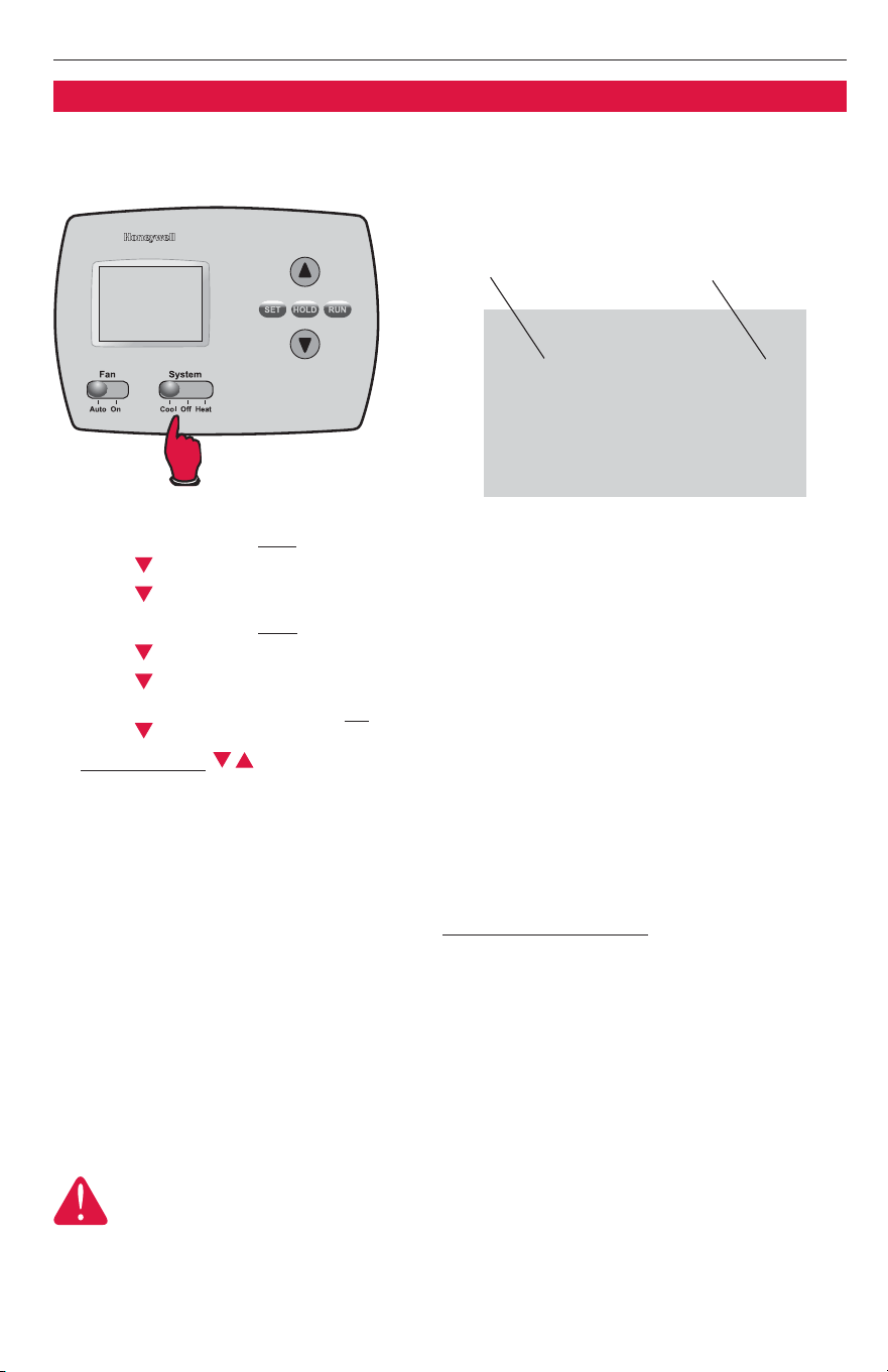
To begin, pr
ess and hold the and
buttons until the display changes
Function number
Press to change settings
Press to advance to next function
Pr
ess and hold to exit and save settings
Setting
Installer setup
Follow the procedure below to configure the thermostat to match the installed
heating/cooling system, and customize feature operation as desired.
Installer system test
After completing the installer setup above, press the button again to begin a
system test (see next page).
Press and hold both buttons
PRO TH4110B Programmable Thermostat
9
10
30
70
Heating system
Cooling system
Thermostat
information
(for reference only)
0 Heat and fan turn off.
1 Heat turns on. Fan also turns on immediately if Fan Operation
Switch is set to Electric Heat/Heat Pump
(see page 6).
0 Compressor and fan turn off.
1 Compressor and fan turn on.
71 Software revision number (major revisions)
72 Software revision number (minor revisions)
73 Configuration identification code (major)
74 Configuration identification code (minor)
75 Production configuration date code (week)
76 Production configuration date code (year)
System Test System Status
Installer system test
CAUTION: EQUIPMENT DAMAGE HAZARD
Compressor protection (minimum off time) is bypassed during testing. To prevent
equipment damage, avoid cycling the compressor quickly.
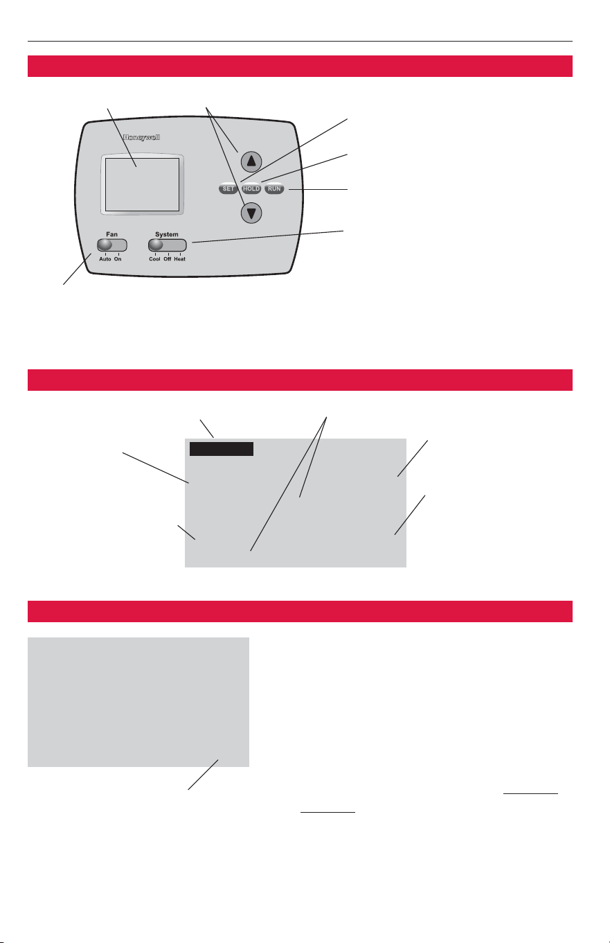
System switch
1 Set
SSYYSSTTEEMM
switch to Cool.
2 Press to turn on cooling system, then check system status (see table, below).
3 Press to turn off cooling system.
4 Set
SSYYSSTTEEMM
switch to Heat.
5 Press to turn on heating system, then check system status (see table, below).
6 Press to turn off heating system.
7 [Optional] Set
SSYYSSTTEEMM
switch to Off to display thermostat information (see table, below).
Press to display 71-76.
8Press and hold to terminate system test at any time.
Follow the procedure below to test the heating and cooling system.
Test
10
0
System test number System status
Inside Set To
75
6:30
AM
75
Wake
Cool
On
°
°
Replace Batt
Installation Guide
10
Quick reference to controls
Digital display screen Temperature adjustment
• Set: Press to set time/day/
schedule
• Hold: Press to override
programmed temperature control
• Run: Press to resume program
schedule
System switch
• Cool: Thermostat controls only
the cooling system.
• Heat: Thermostat controls only
the heating system.
• Off: Heating and cooling
systems are off.
Fan switch
On: Fan runs continuously.
Auto: Fan runs only when heating
or cooling system is on.
Built-in compressor protection (Setup Function 15)
This feature helps prevent damage to the
compressor in the air conditioning or heat
pump system.
Damage can occur if the compressor is re-
started too soon after shutdown.This feature
forces the compressor to wait for a few
minutes before restarting.
During the wait time, the message Cool On
(or Heat On if you have a heat pump) will
flash on the display.When the safe wait time
has elapsed, the message stops flashing and
the compressor turns on.
Quick reference to display screen
Current inside
temperature
Low battery warning Current day/time
Current program period
Wake/Leave/Return/Sleep
Temperature setting
System status
(Heat On, Cool On)
Inside Set To
75
6:30
AM
75
Cool
On
°
°
Message flashes until safe
restart time has elapsed
Wed
Wake
Wed

PRO TH4110B Programmable Thermostat
11
In case of difficulty
If you have difficulty with your thermostat, please try the suggestions below. Most
problems can be corrected quickly and easily.
Display is blank • Make sure fresh AA alkaline batteries are correctly installed (see page 7).
Fan does not
turn on in a
call for heat
• Make sure the Fan Operation switch is set to the proper system (see page 6).
Heating system
does not respond
(“Heat On”
appears on
screen)
• Check for 24 Vac at the equipment on the secondary side of the trans-
former between power and common. If voltage is not present, check the
heating equipment to find the cause of the problem.
• Check for 24 Vac between the heat terminal (W) and the transformer
common. If 24 Vac is present, the thermostat is functional. Check the
heating equipment to find the cause of the problem.
• Check for loose or broken wires between the thermostat and the heating
equipment.
Cooling system
does not respond
(“Cool On”
appears on
screen)
• Check for 24 Vac at the equipment on the secondary side of the trans-
former between power and common. If voltage is not present, check the
cooling equipment to find the cause of the problem
• Check for 24 Vac between the cooling terminal (Y) and the transformer
common. If 24 Vac is present, the thermostat is functional. Check the
cooling system to find the cause of the problem.
• Check for loose or broken wires between the thermostat and the cooling
equipment.
Temperature
settings do not
change
Make sure heating and cooling temperatures are set to acceptable ranges:
• Heat: 40° to 90°F (4.5° to 32°C).
• Cool: 50° to 99°F (10° to 37°C).
“Cool On” or
“Heat On”
is flashing
• Compressor protection timeout is engaged. Wait 5 minutes for the
system to restart safely, without damage to the compressor.
“Heat On” is
not displayed
• Set the System switch to Heat
, and set the temperature level above the
current room temperature (see page 10).
“Cool On” is
not displayed
• Set the System switch to Cool
, and set the temperature level below the
current room temperature (see page 10).

Installation Guide
12
Accessories
Please contact your distributor to order accessories.
Cover plate assembly ............................................Part Number 50002883-001
(Used to cover marks left by old thermostats.)
Specifications
Temperature Ranges
• Heat: 40° to 90°F (4.5° to 32°C)
• Cool: 50° to 99°F (10° to 37°C)
Operating Ambient Temperature
• 32° to 120°F (0° to 48.9°C)
Shipping Temperature
• -20° to 120°F (-28.9° to 48.9°C)
Operating Relative Humidity
• 5% to 90% (non-condensing)
Physical Dimensions
• 3-13/16” H x 5-3/8” W x 1-1/4” D
• 97 mm H x 137 mm W x 32 mm D
Electrical Ratings
System Voltage (50/60Hz) Running Current
Heating 20-30 Vac 0.02-1.0 A
(Powerpile) 750 mV DC 100 mA DC
Cooling 20-30 Vac 0.02-1.0 A


Honeywell International Inc.
1985 Douglas Drive North
Golden Valley, MN 55422
www.honeywell.com/yourhome
Automation and Control Solutions
Honeywell Limited-Honeywell Limitée
35 Dynamic Drive
Scarborough, Ontario M1V 4Z9
Printed in U.S.A. on recycled
paper containing at least 10%
post-consumer paper fibers.
® U.S. Registered Trademark.
© 2005 Honeywell International Inc.
Patents pending. All rights reserved.
69-1769 02
-2005