rev. 1
1
Feeder Controller InstallaƟon Manual
The controller is designed to communicate with and control equipment
manufactured by WiseEye partner companies. The controller can operate
in two different modes: Manual or Auto. Weather the controller is in
Manual or Auto determines how it will transmit. The selected mode will
determine if it transmits via BLE or LTE. The controller is only designed to
transmit by one of these modes at Ɵme. This allows the end user to use
this controller however they see fit. The controller is for outdoor
equipment that is in remote areas that seldom will need to be accessed.
For this reason, there will be liƩle interacƟon with the controller once it is
acƟvated. While it is acƟve it will be placed in a metal housing with a
metal door protecƟng it from the elements and ensuring that only
qualified individuals have access.
Manual
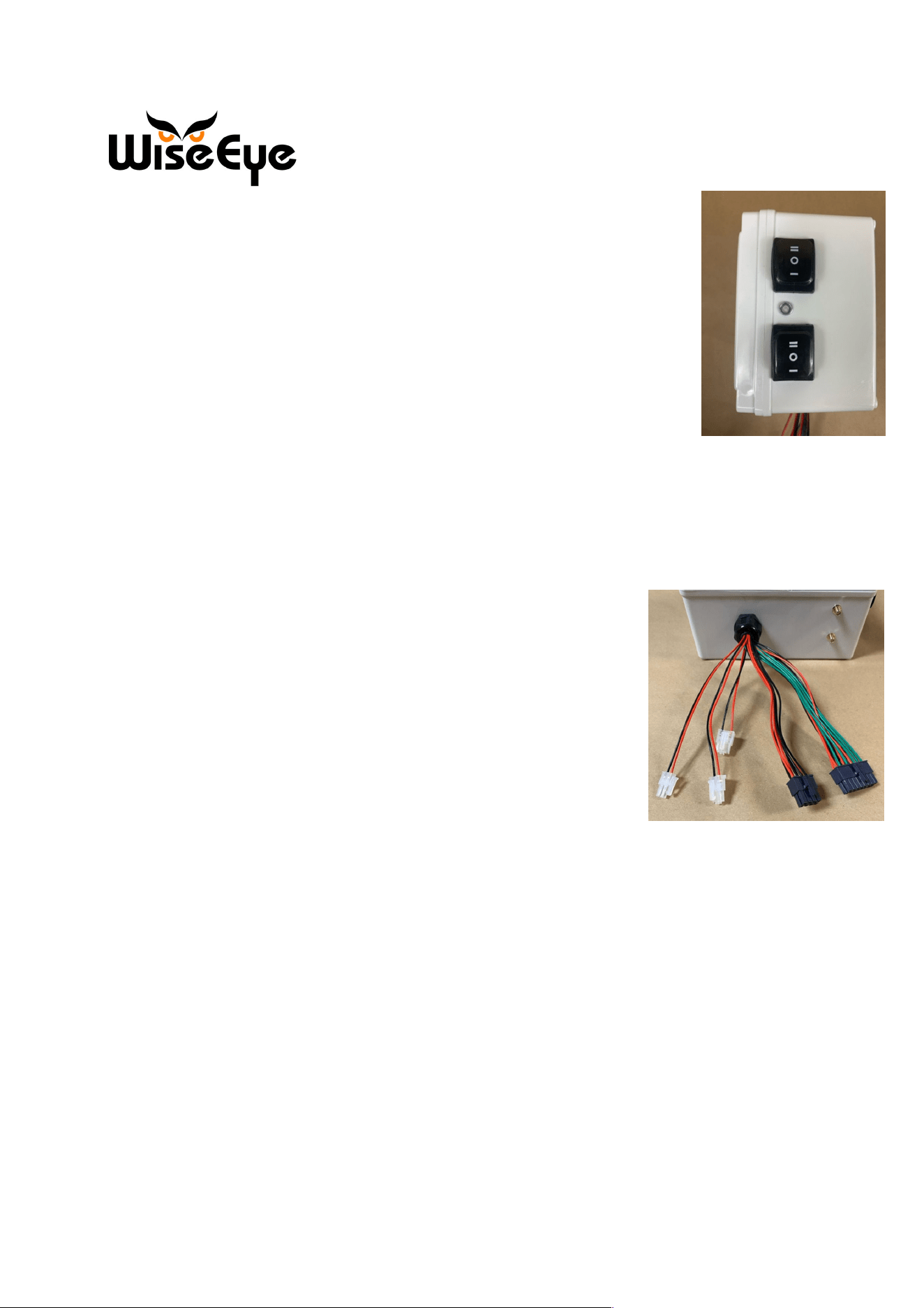
On the controller’s right-hand side there are two, 3 posiƟon switches. The
boƩom switch is a three-posiƟon latching switch. If this switch is toggled to
the Manual mode (the up posiƟon), it will allow the controller to funcƟon in
Manual mode. In Manual mode, using Bluetooth it will search for nearby
mobile devices so that it can connect to them. Once connected, the controller
will have access to the HuntControl 2.0 applicaƟon. For in-depth review of
how to use the HuntControl 2.0 applicaƟon, please review the Feed I.D. user
Manual.
When the controller is in Manual mode the momentary switch (top switch)
can be used to actuate the actuators that are aƩached to the equipment. If
the momentary switch is toggled to the open posiƟon the rams will retract opening the feeder
door. If the momentary switch is toggled to the close posiƟon the rams will extend, closing the
feeder door.
Open
Close
Manual
Manual
Open
Close
Manual
rev. 1
2
Auto
When the controller’s latching switch (BoƩom Switch) is toggled to Auto mode
(the down posiƟon) the controller will use LTE to connect to MQTT. Once
MQTT is connected then it can send informaƟon and receive commands from
the HuntControl applicaƟon.
Sensor-Based OperaƟons
If the controller loses cellular connecƟon while in Auto mode it will default to
sensor-based operaƟon. When in sensor-based operaƟon, the controller will
operate the feeder based on signals from the peripheral sensors. The
controller will aƩempt to reconnect five Ɵmes aŌer LTE signal is lost. The reconnect aƩempts
lasƟng no longer then a few minutes. For in-depth review of how to use the HuntControl 2.0
applicaƟon, please review the Feed I.D. user Manual.
Antenna
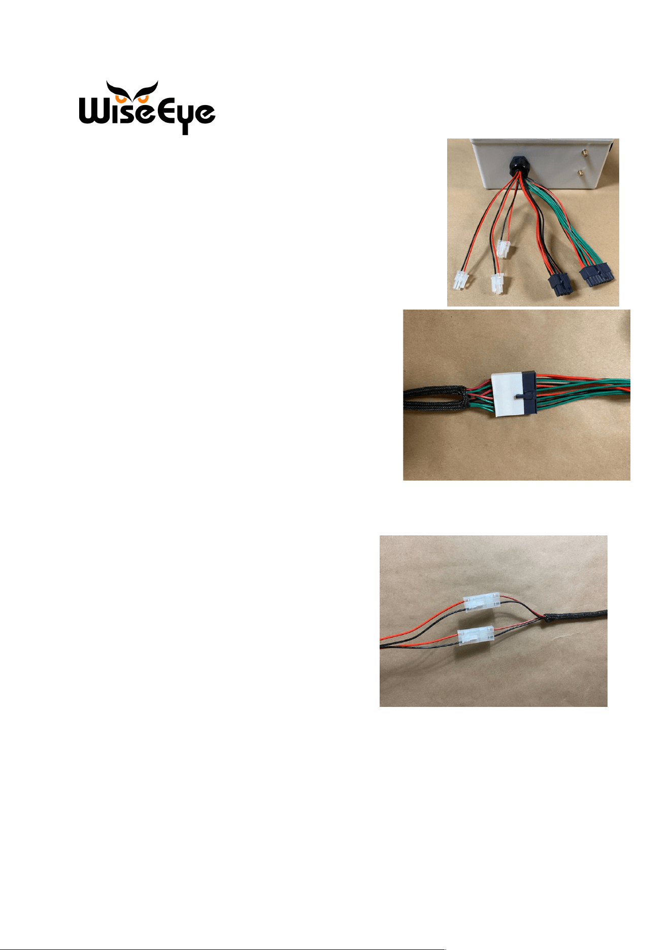
At the base of the controller are two SMA antenna extension cables
that lead back to the LTE module. The male SMA antenna connecƟon
connects to an external all-in-one GPS and 4G antenna.
GPS
At the base of the controller, the SMA connector nearest the lid of the
controller is for GPS. This is used when the controller is in Auto mode
to report the posiƟon of the controller.
LTE
Below the SMA connector for GPS is the LTE SMA connector. This allows the controller to
connect to the local cellular network.
Wire Harness
Protruding from the base of the controller is five wire harness. Each harness has a specific
funcƟon that is necessary for the operaƟon of the controller. The connectors are: 16 pin female
Molex connector, 8 pin female Molex connector, 3 pin female connector (2), 2 pin female
connector.
1. 16 pin connector- The 16 pin connector connects the external sensors to the controller
GPS
4G
Auto
rev. 1
3
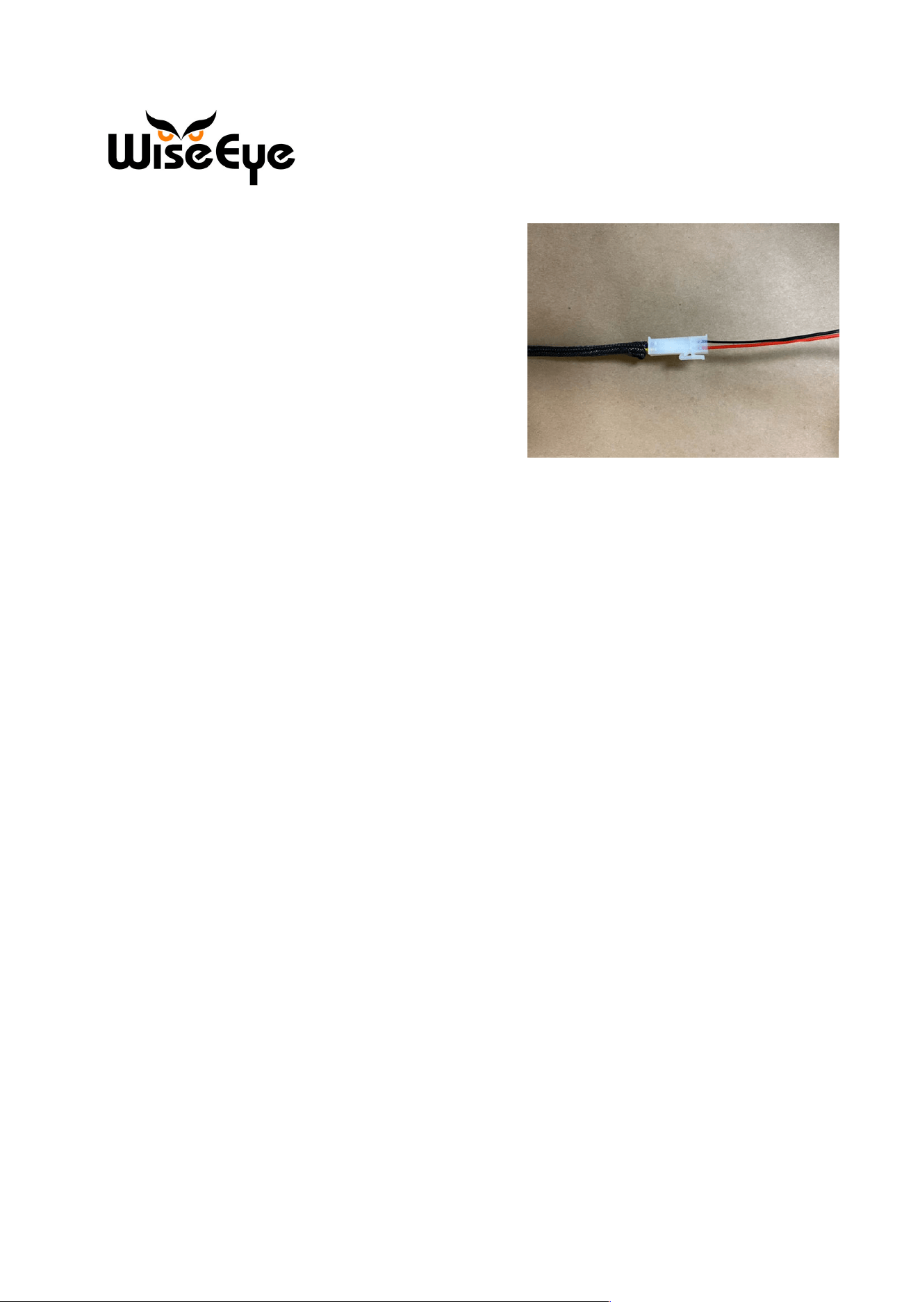
2. 8 pin connector- The 8 pin connector connects external
safety features to the controller
3. 3 pin connector- The pair of 3 pin connectors connects the
external baƩery source (12v 8Ah baƩery)
4. 2 pin connector- The 2 pin connector connects the pair of
actuators to the controller
Main Wire Harness
Protruding from the base of the controller is the main wire
harness tasked with connecƟng the peripheral sensors to
the controller. These sensors are used to indicate different
environmental factors that can influence the behavior of
the feeder. For in-depth review of the peripheral sensors
please review the Feed I.D. user Manual. (Harness #1)
PCB Power and Actuator Power
Protruding from the base of the controller is two 3-pin
connectors. These connectors are responsible for
connecƟng the controller to an exterior power source.
The exterior power source brings power to both the
PCB and the actuators. (Harness #3
4
3
2
1
4
rev. 1
4
Actuator Connector
Protruding from the base of the controller is a Molex 2-
pin connector. This connector connects the controller
to the actuator allowing the actuator to receive acƟon
commands. When the actuator is under load and
extending to its fullest length it will pull 15.71 Ap.
(Harness #4)
Peripheral Device and Sensor connector
Protruding from the base of the controller is a Molex 8-pin connector. This connector connects
the controller to any peripheral devices or sensors that may need an in-line relay.
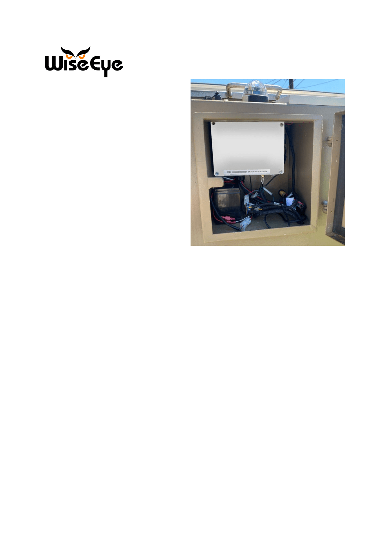
InstallaƟon steps
When installing the controller there is a few steps that are necessary to bolt the controller to
the feeder.
Step One (Controller MounƟng)
1. Install the mounƟng bracket in a verƟcal posiƟon
2. Using a tape measure measuring from the floor of the controller cabinet making at 4
5/8” . This marks the boƩom horizontal alignment line for the controller. Once again
taking a tape measure and measuring from the right inside wall of the inner controller
cabinet make a mark at 1 ¾”. With these alignment marks in place, press the controller
against the mounƟng surface and align it with the mounƟng marks and then mark the
holes for the mounƟng brackets.
3. Once the holes are marked for the mounƟng brackets, predrill the holes with a 5/32”
drill bit.
4. AŌer the holes are drilled place the controller in the controller cabinet and start the 10-
16x3/4” self-drilling screw in the top-right conner and Ɵghten it. Once that has been
accomplished repeat the process in the opposite corners.
Step Two (Cable RouƟng)
rev. 1
5
1. AŌer the controller is installed as well
as the GPS/LTE antenna and external
sensors use a magnet cable Ɵe wrap
mounts for cable management.
2. Once the cables have been routed
down to the boƩom of the cabinet
connect the antenna cables (see the
secƟon named antenna) and the
Molex connectors to the appropriate
Molex connector (see the separate
secƟon on Molex connectors).

rev. 1
6
FCC Statement:
This device complies with part 15 of the FCC Rules. OperaƟon is subject to the following two
condiƟons:
(1) This device may not cause harmful interference, and
(2) this device must accept any interference received, including interference that may cause
undesired operaƟon.
This equipment has been tested and found to comply with the limits for a Class A digital device,
pursuant to part 15 of the FCC Rules. These limits are designed to provide reasonable
protection against harmful interference when the equipment is operated in a commercial
environment. This equipment generates, uses, and can radiate radio frequency energy and, if
not installed and used in accordance with the instruction manual, may cause harmful
interference to radio communications. Operation of this equipment in a residential area is likely
to cause harmful interference in which case the user will be required to correct the interference
at his own expense.
FCC CauƟon:
Any changes or modificaƟons not expressly approved by the party responsible for compliance
could void the user's authority to operate this equipment.
This equipment complies with FCC radiaƟon exposure limits set forth for an uncontrolled
environment.
This equipment should be installed and operated with minimum distance of 20cm between the
radiator & your body.
This device contained FCC ID: XMR201909EG91NAX