Before attempting to connect or operate this product,
please read these instructions carefully and save this manual for future use.
User's Manual
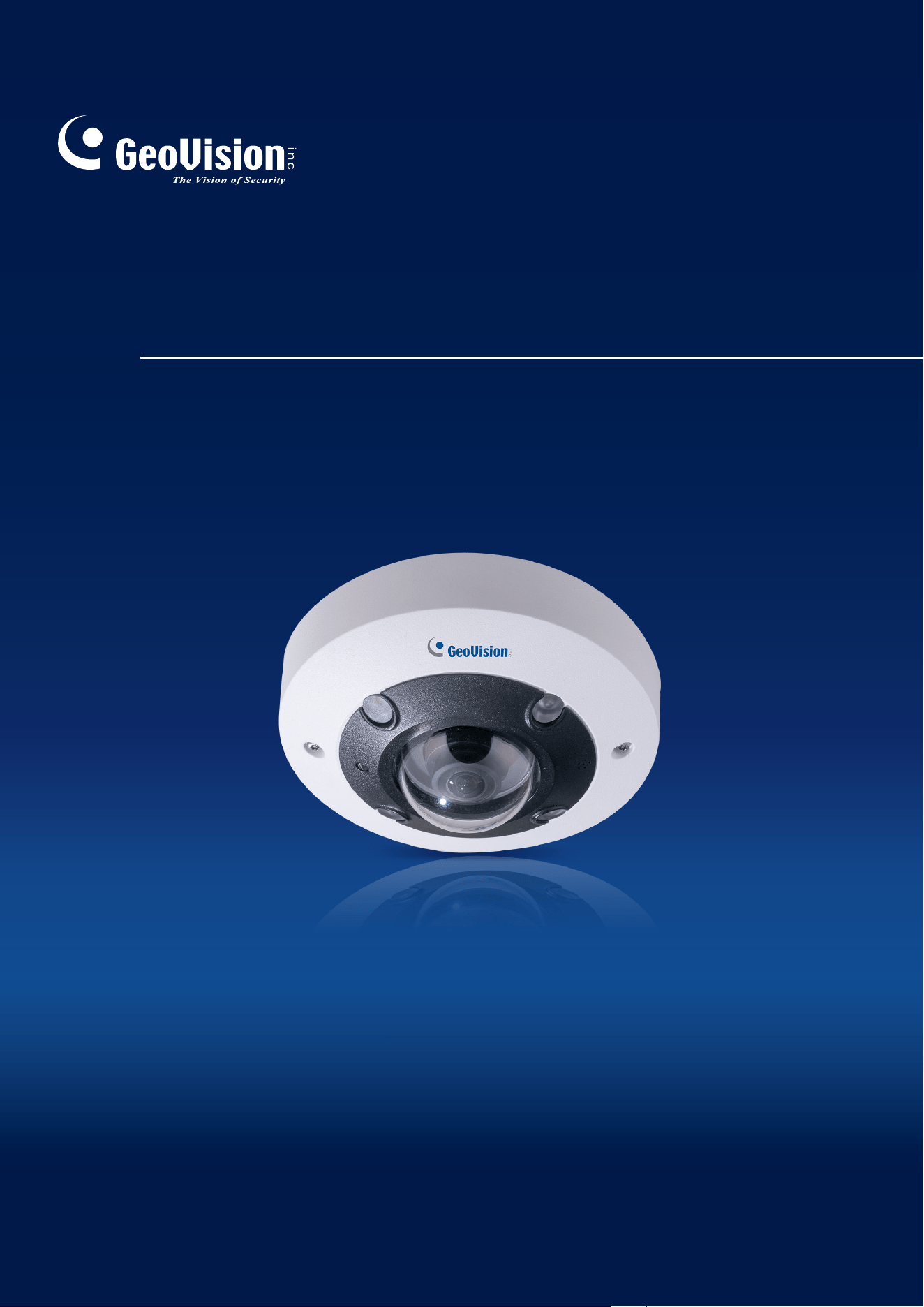
GV-QFER12700
QFER-UM-B

© 2023 GeoVision, Inc. All rights reserved.
Under the copyright laws, this manual may not be copied, in whole or in part,
without the written consent of GeoVision.
Every effort has been made to ensure that the information in this manual is
accurate. GeoVision, Inc. makes no expressed or implied warranty of any kind
and assumes no responsibility for errors or omissions. No liability is assumed
for incidental or consequential damages arising from the use of the information
or products contained herein. Features and specifications are subject to
change without notice.
GeoVision, Inc.
9F, No. 246, Sec. 1, Neihu Rd.,
Neihu District, Taipei, Taiwan
Tel: +886-2-8797-8377
Fax: +886-2-8797-8335
http://www.geovision.com.tw
Trademarks used in this manual: GeoVision, the GeoVision logo and GV
series products are trademarks of GeoVision, Inc. Windows is the registered
trademark of Microsoft Corporation.
June 2023
Scan the following QR codes for product warranty and technical support
policy:
[Warranty] [Technical Support Policy]
1
Preface
Welcome to the GV-QFER12700 User’s Manual.
This Manual provides an overview of GV-QFER12700 and its accessories. The
instructions herein will guide you through the installation and use of GV-
QFER12700.
Note: GV-QFER12700 can be installed to the wall, ceiling, or corner with GV-Mount200 / 203
/ 206-1 / 300-1 / 310-1 / 903-2 / 904-2 / 912-1 / 919. Refer to the following sections and
documents.
• GV-Mount200 / 300-1 / 903-2 (5.7 Convex Corner Mount, GV-Mount Accessories
Installation Guide)
• GV-Mount200 / 310-1 / 903-2 (5.9 Concave Corner Mount, GV-Mount Accessories
Installation Guide)
• GV-Mount203 / 300-1 / 903-2 (5.8 Convex Corner Box Mount, GV-Mount Accessories
Installation Guide)
• GV-Mount 206-1 (5.4.2 GV-FER5701 / FER12203 / FER12700 / EFER3700 /
EFER3700-W / QFER12700, GV-Mount Accessories Installation Guide)
• GV-Mount903-2 (5.1.2 GV-EFER3700 / GV-EFER3700-W / GV-QFER12700, GV-Mount
Accessories Installation Guide)
• GV-Mount904-2 (5.6.2 GV-Mount904-1, GV-Mount Accessories Installation Guide)
• GV-Mount912-1 (5.12 Power Box Mount, GV-Mount Accessories Installation Guide)
• GV-Mount919 (Appendix C: In-Ceiling Mount Installation, GV-QFER12700 User’s Manual)

2
Table of Contents
Regulatory Notices ..........................................................................................................................3
Note for Connecting to GV-VMS / DVR / NVR.................................................................................4
Note for Recording ..........................................................................................................................4
Optional Devices..............................................................................................................................5
1. Overview....................................................................................................................................6
2. Main Tabs ..................................................................................................................................7
2.1 Home Page ............................................................................................................... 8
2.2 System .................................................................................................................... 11
2.2.1
System............................................................................................................................................................11
2.2.2
Security ......................................................................................................................................................... 13
2.2.3
Network......................................................................................................................................................... 21
2.2.4
DDNS............................................................................................................................................................ 28
2.2.5
Mail ............................................................................................................................................................... 28
2.2.6
FTP................................................................................................................................................................ 29
2.2.7
HTTP............................................................................................................................................................. 29
2.2.8
Events (Alarm Settings) ................................................................................................................................. 30
2.2.9
Storage Management ..................................................................................................................................... 57
2.2.10
Recording...................................................................................................................................................... 61
2.2.11
Schedule........................................................................................................................................................ 62
2.2.12
File Location (Snapshots and Web Recording) .............................................................................................. 63
2.2.13
View Information........................................................................................................................................... 64
2.2.14
Factory Default .............................................................................................................................................. 65
2.2.15
Software Version (Firmware Version)............................................................................................................ 65
2.2.16
Software Upgrade (Firmware Upgrade) ........................................................................................................ 66
2.2.17
Maintenance .................................................................................................................................................. 67
2.3 Streaming ............................................................................................................... 68
2.3.1
Video Configuration (Video Format & Resolution) ....................................................................................... 69
2.3.2
Video Rotation............................................................................................................................................... 71
2.3.3
Video Text Overlay........................................................................................................................................ 72
2.3.4
Video ROI Encoding..................................................................................................................................... 74
2.3.5
Video OCX Protocol...................................................................................................................................... 74
2.3.6
Video Mask ................................................................................................................................................... 75
2.3.7
Audio (Audio Mode and Bit Rate Settings).................................................................................................... 76
2.4 Image ...................................................................................................................... 77
2.4.1
Exposure ....................................................................................................................................................... 78
2.4.2
White Balance................................................................................................................................................ 79
2.4.3
Picture Adjustment......................................................................................................................................... 81
2.4.4
Color Style .................................................................................................................................................... 82
2.4.5
IR Function.................................................................................................................................................... 83
2.4.6
Noise Reduction ............................................................................................................................................ 85
2.4.6
WDR Function............................................................................................................................................... 86
2.4.7
Backlight ....................................................................................................................................................... 86
2.4.8
Profile............................................................................................................................................................ 86
2.4.9
Fisheye Setting .............................................................................................................................................. 87
2.4.10
TV System..................................................................................................................................................... 89
2.5 Logout..................................................................................................................... 89
Appendix A: Install UPnP Components ........................................................................................90
Appendix B: IP Addresses from Decimal to Binary .....................................................................91
Appendix C: In-Ceiling Mount Installation....................................................................................92
Appendix D: Dimensions...............................................................................................................94
3
Regulatory Notices
FCC Notice
This equipment has been tested and found to comply with the limits of a Class A digital
device, pursuant to part 15 of the FCC Rules. These limits are designed to provide
reasonable protection against harmful interference when the equipment is operated in a
commercial environment.
Class A
This equipment generates, uses, and can radiate radio frequency energy and, if not installed
and used in accordance with the instruction manual, may cause harmful interference to radio
communications. Operation of this equipment in a residential area is likely to cause harmful
interference in which case the users will be required to correct the interference at their own
expense.
CE Notice
This is a Class A product. In a domestic environment, this product may cause radio
interference in which case the users may be required to take adequate measures.
RoHS Compliance
The Restriction of Hazardous Substances (RoHS) Directive is to forbid the use of hazardous
materials for production. To meet the RoHS Directive requirements, this product is made to
be RoHS compliant.
WEEE Compliance
This product is subject to the Waste Electrical and Electronic Equipment (WEEE) Directive
and made compliant with the WEEE requirements.

4
Note for Connecting to GV-VMS / DVR / NVR
The GV-QFER12700 is designed to work with and record on GV-VMS / DVR / NVR, a video
management system.
Once the camera is connected to the GV-VMS / DVR / NVR, the resolution set on the GV-
VMS / DVR / NVR will override the resolution set on the camera’s Web interface. You can
only change the resolution settings through the Web interface when the connection to the
GV-VMS / DVR / NVR is interrupted.
Note: Currently, only GV-VMS, applied with the patches, supports GV-QFER12700.
Note for Recording
1. By default, the images are recorded to the memory card inserted in the GV-IP Seed
Dome.
2. Mind the following when using a memory card for recording:
Recorded data on the memory card can be damaged or lost if the data are accessed
while the camera is under physical shock, power interruption, memory card
detachment or when the memory card reaches the end of its lifespan. No guarantee is
provided for such causes.
The stored data can be lost if the memory card is not accessed for a long period of
time. Back up your data periodically if you seldom access the memory card.
Memory cards are expendable and their durability varies according to the conditions
of the installed site and how they are used. Back up your data regularly and replace
the memory card annually.
To avoid power outage, it is highly recommended to apply a battery backup (UPS).
For better performance, it is highly recommended to use Micro SD card of MLC NAND
flash, Class 10.
Replace the memory card when its read/write speed is lower than 6 MB/s or when the
memory card is frequently undetected by the camera.
3. To ensure smooth network usage, do not access the live view from more than 20
connections.
5
Optional Devices
Optional devices can expand the capabilities and versatility of your GV-QFER12700. Contact
your dealer for more information.
Device Description
GV-Mount Accessories
The GV-Mount Accessories provide a comprehensive
lineup of accessories for installing the GV-QFER12700
on the ceiling or wall. For details, refer to Appendix C:
In-Ceiling Mount Installation, GV-QFER12700 User’s
Manual or GV-Mount Accessories Installation Guide.
GV-PoE Power Adapter
GV-PoE Adapter is designed to provide power to the
IP device through a single Ethernet cable. Adopting
the PoE adapter enables you to mount an IP device
anywhere in a building where power outlets are not
available.
GV-PoE Switch
The GV-POE Switch is designed to provide power
along with network connection for IP devices. The GV-
POE Switch is available in various models with
different types and numbers of ports.
Power Adapter
Contact our sales representatives for the countries
and areas supported.

Overview
6
1
1. Overview
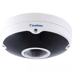
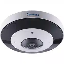
GV-QFER12700 is a high-performance surveillance solution and features 360°
wide coverage without blind spots. The fisheye camera supports up to 12
Megapixels resolution streaming and maintains at 20 fps that allows the video
stream can be viewed smoothly. Moreover, the fisheye camera supports various
view mode (digital PTZ, panoramic view, etc.) which allows users to choose
based on their own preference. GV-QFER12700 is suitable to apply in wide
open space environments like office rooms, hotel lobby, apartment front door,
etc.
In addition, the embedded edge dewarping engine enables the camera to
dewarp images by the camera itself rather than consuming resources from the
backend devices. The camera also includes IR LED module and Smart
Picture/Quality/Noise Reduction features that improves the image quality in low
light environment.

Main Tabs
7
2
2. Main Tabs
There are six setting tabs, including <Home>, <System>, <Streaming>,
<Camera>, <PTZ> and <Logout> on the Home Page.
Home
Users can monitor the live video of the targeted area.
System Setting
The administrator can set system time, root password, network related
settings, etc. Further details will be interpreted in chapter System.
Streaming Setting
The administrator can configure video format, video compression, video OCX
protocol, video frame rate and audio compression in this page.
Image Setting
This setting page is only available for the administrator and user accounts that
have been granted the privilege of camera control. The administrator and users
can adjust various camera parameters including Exposure, White Balance,
Picture Adjustment, Color Style, IR Function, Digital Zoom, WDR, etc.
Logout
Click the tab to re-login the camera with another username and password.
8
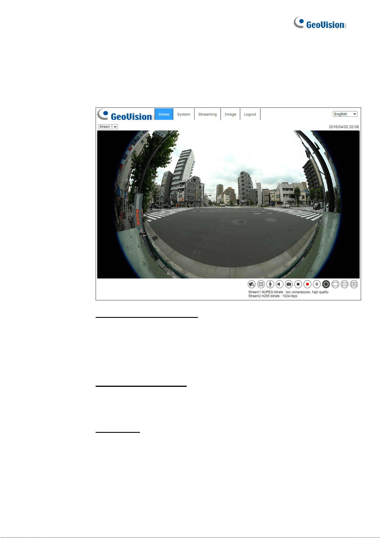
2.1 Home Page
Click the tab <Home> to access the <Home> Page. There are several
function buttons on this page. See the detailed information of each
item below.
Multiple Languages Support
Multiple languages are supported, including Czech, English, French,
German, Hungarian, Italian, Japanese, Portuguese, Russian, Spanish,
Traditional Chinese, and Simplified Chinese for the viewer window
interface.
Display Stream Selection
According to the streaming setting, users can choose the one stream to
display from the drop-down list.
Camera Info
Double click the live view pane, and the camera info window will pop up.
Users can instantaneously check the basic information of the
camera, such as IP address, network status, video format, etc.
Main Tabs
9
2
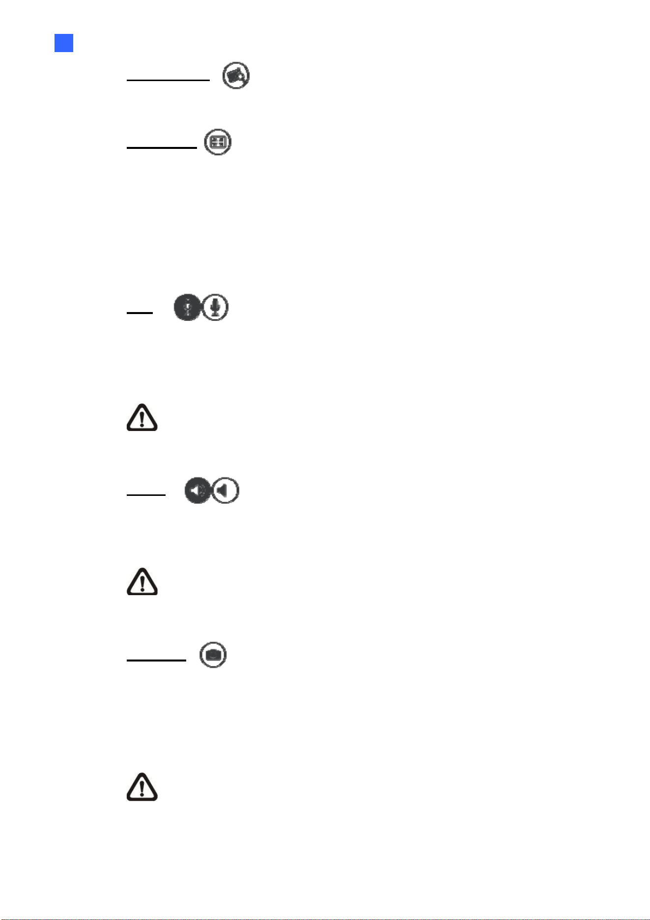
Video Quality
Click to show/hide bitrate and compression of each stream.
Full Screen
Image display size can be adjusted to full screen. Alternatively, right click the
Live Video Pane and select <Fullscreen> to go full screen.
To exit full screen mode, users can (1) tap <Esc> on the keyboard; (2) double
click the Live Video Pane; (3) right click the Live Video Pane and select
<Normal view>.
Talk (On / Off)
Talk function allows the local site talks to the remote site. Click the button to
switch it to On / Off. Users must select the suitable transmission mode under this
path: Streaming> Audio to enable this function.
NOTE: This function is only available for user accounts that have been
granted this privilege by the administrator. Please refer to Security: Add
user> Talk/Listen for further details.
Listen (On / Off)
Click the <Listen> button to mute / activate the audio. Users must select the
suitable transmission mode under <Streaming> Audio to enable this function.
NOTE: This function is only available for user accounts that have been
granted this privilege by the administrator. Please refer to Security:
Add user> Talk/Listen for further details.
Snapshot
Click the button and the JPEG snapshots will automatically be saved in the
appointed place: C:\ProgramData\Geovision\. To change the storage
location, please refer to section File Location of the next chapter for further
details.
NOTE: With Windows 7 operating system or above, to implement the
Snapshot function, users must run IE as administrator. To run IE as
administrator, right click the IE browser icon and select “Run As
Administrator” to launch IE.
10
Live View Pause / Restart (Pause / Restart)
Click < > to disable video streaming, the live video will be displayed as black.
Press < > to show the live video.
Record (O
n / Off)
Click the <Record> button and the Live View through the web browsing will be
directly recorded to the specific location on the local hard drive, which could be
configured in the <File Location> page. The default storage location for the
web recording is: C:\ProgramData\Geovision\. Please refer to section File
Location of the next chapter for further details.
NOTE: With Windows 7 operating system or above, to implement the
Web Recording function, users must run IE as administrator. To run IE
as administrator, right click the IE browser icon and select “Run As
Administrator” to launch IE.
Manual Trigger (On / Off)
Click the <Manual Trigger > button to turn on and off the manual trigger. Please
refer to section Manual Trigger of the next chapter for further details.
Fisheye Image Adjustment
Pan/Tilt Control
Users can implement pan/tilt control by moving the cursor to the live video
pane,
then left click and drag the pointer in any direction.
Optical Zoom Control
In Full Screen display mode, users can implement zoom in / out by
scrolling up/down the mouse wheel.
Main Tabs
11
2
2.2 System
Under the tab <System>, the categories are shown as the configure page
below.
NOTE: The <System> configuration page is only accessible by the
administrator.
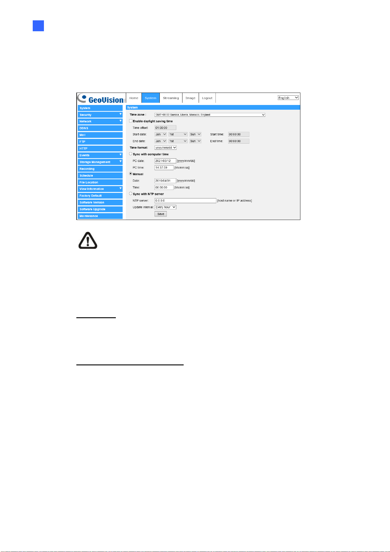
2.2.1
System
The System setting can be found under the path: System > System.
Time Zone
Select the time zone from the drop-down menu according to the location of the
camera.
Enable Daylight Saving Time
To enable DST, please check the item and then specify the time offset and the
DST duration. The format for time offset is [hh:mm:ss]; for instance, if the
amount of time offset is one hour, please enter “01:00:00” into the field.
12
Time format
Choose a time format (yyyy/mm/dd or dd/mm/yyyy) from the drop-down menu.
The format of the date and time displayed above the live video window will be
changed according to the selected format.
Sync with Computer Time
Select the item, and video date and time display will synchronize with the PC’s.
NOTE: Users MUST click the <Save> button to confirm the setting.
Otherwise, the time will not be synced.
Manual
The administrator can set video date and time manually. Entry format should be
identical with the examples shown next to the enter fields.
Sync with NTP Server
Network Time Protocol (NTP) is an alternate way to synchronize the camera’s
clock with a NTP server. Please specify the server that is wished to synchronize
in the entry field. Then select an update interval from the drop-down menu.
For further information about NTP, please see the web site: www.ntp.org.
NOTE: The synchronization will be done every time the camera boots
up.
Click the <Save> button to confirm the setting.
Main Tabs
13
2
2.2.2
Security
The Security setting can be found under this path: System> Security.
Click the <Security> category, there will be a drop-down menu with tabs
including <User>, <HTTPS>, <IP Filter>, and <IEEE 802.1X>.
2.2.2.1 User
The User setting can be found under this path: System> Security> User.
Admin Password
This item is for the administrator to reset password. Enter the new password in
<Admin password> and <Confirm password>. The maximum length is 14
characters. The input characters / numbers will be displayed as dots for security
purposes. Click the <Save> button to confirm the changes. After the changes
are confirmed, the web browser will ask the administrator to re-login to the
camera with the new password.
NOTE: The following characters are valid: A-Z, a-z, 0-9, !#$%&’-.@^_~.
Add User
This item is for the administrator to add new users. Enter the new user’s name
in <User name> and the password in <User password>. Username can be up to
16 characters, and the maximum length of the password is 14 characters. Tick
the boxes below to give privileges for functions, including “Camera control”,
“Talk” and “Listen”. Click the <Add> button to add the new user. The name of
the new added user will be displayed in the <User name> drop-down list under
<Manage User>. There is a maximum of twenty user accounts.
I/O access
This item supports fundamental functions that enable users to view the
live video when accessing to the camera.
Camera control
This item allows the appointed user to change camera parameters on
the <Camera> and <PTZ> setting page.

14
Talk/Listen
This item allows the appointed user in the local site (PC site) to
communicate with, for instance, the administrator in the remote site.
Manage User
Delete user
Pull down the <User name> drop-down list and select the username that
is wished to be deleted. Click the <Delete> button to remove the
selected name.
Edit user
Pull down the <User name> drop-down list and select the username.
Click the <Edit> button and a popup window will appear. In the appeared
window, enter the new user password and reset the privileges. Click the
<Save> button to confirm the changes. Then click the <Close> button to
complete the editing.
HTTP Authentication Setting
This setting allows secured connections between the IP camera and web
browser by enforcing access controls to web resources. When users approach
to the web browser, it’ll ask for username and password, which protects the
camera settings or live streaming information from snooping. There are two
security models available: Basic and Digest. Refer to the descriptions below for
more details.
Basic
This mode can only provide basic protection for the connection security.
There will still be risks for the password being intercepted.
Digest
Digest mode is a safer option for protection. The password is sent in an
encrypted format to prevent it from being stolen.
NOTE: Users MUST click the <Save> button to apply the setting.

Main Tabs
15
2
Streaming Authentication Setting
This setting provides security against unauthorized users from getting streaming
via Real Time Streaming Protocol (RTSP). If the setting is enabled, users will be
requested to enter user name and password before viewing the live streams.
There are three security modes available: Disable, Basic and Digest. Refer to
the descriptions below for more details.
Disable
If disable mode is selected, there will be no security provided to against
unauthorized access. Users will not be asked to input user name and
password for authentication.
Basic
This mode can only provide basic protection for the live streams.
There will still be risks for the password being intercepted.
Digest
Digest mode is a safer option for protection. The password is sent in an
encrypted format to prevent it from being stolen.
NOTE: Users MUST click the <Save> button to apply the setting.
Enable Account Lockout Function
This setting provides extra security against unauthorized users who intend to log
in by guessing the username or password. If the setting is enabled, login will not
be allowed for the set duration once the maximum login failure is reached.
Threshold
Set the maximum number of login failure.
Duration
Set the duration for account lockout.
NOTE: Users MUST click the <Save> button to apply the setting.
16
2.2.2.2 HTTPS
The HTTPS setting can be found under this path: System> Security> HTTPS.
<HTTPS> allows secure connections between the camera and the web browser
using <Secure Socket Layer (SSL)> or <Transport Layer Security (TLS)>, which
ensure camera settings or Username / Password info from snooping. It is
required to install a self-signed certificate or a CA-signed certificate for
implementing HTTPS.
To use HTTPS on the camera, an HTTPS certificate must be installed. The
HTTPS certificate can be obtained by either creating and sending a certificate
request to a Certificate Authority (CA) or creating a self-signed HTTPS
certificate, as described below.
Create Self-signed Certificate
Before a CA-issued certificate is obtained, users can create and install a self-
signed certificate first.
Click the <Create> button under “Create self-signed certificate” and provide the
requested information to install a self-signed certificate for the camera.
Please refer to the last part of this section Provide the Certificate Information for
more details.
NOTE: The self-signed certificate does not provide the same high level
of security as when using a CA-issued certificate.
Install Signed Certificate
Click the <Create Certificate Request> button to create and submit a certificate
request in order to obtain a signed certificate from CA.
Provide the request information in the create dialog. Please refer to the
following section Provide the Certificate Information for more details.
When the request is complete, the subject of the Created Request will be shown
in the field. Click the <Properties> button below the Subject field, copy the
PEM-formatted request and send it to the selected CA.
When the signed certificate is returned, install it by uploading the signed
certificate.

Main Tabs
17
2
Provide the Certificate Information
To create a Self-signed HTTPS Certificate or a Certificate Request to CA,
please enter the information as requested.
Create Self Signed Certificate Create Certificate Request
Country
v v
State or Province
v v
Locality
v v
Organization
v v
Organizational Unit
v v
Common Name
v v
Valid Days
v -
Country
Enter a two-letter combination code to indicate the country the certificate
will be used in. For instance, type in “US” to indicate United States.
State or province
Enter the local administrative region.
Locality
Enter other geographical information.
Organization
Enter the name of the organization to which the entity identified in
“Common Name” belongs.
Organization Unit
Enter the name of the organizational unit to which the entity identified in
“Common Name” belongs.
Common Name
Indicate the name of the person or other entity that the certificate
identifies (often used to identify the website).
Valid days
Enter the period in days (1 to 9999) to indicate the valid period of
certificate.
Click the <OK> button to save the Certificate Information after completing the
setting.

18
2.2.2.3 IP Filter
The IP Filter setting can be found under this path: System> Security> IP Filter.
With IP Filter, users can allow or deny specific IP addresses from accessing the
camera.
Enable IP Filter
Check the box to enable the IP Filter function. Once enabled, the listed
IP addresses (IPv4) in the <Filtered IP Addresses> list box will be
allowed / denied to access the camera.
Select <Allow> or <Deny> from the drop-down list and click the <Apply>
button to determine the IP filter behavior.
Add IP Address
Input IP address at the blank space below the <Filtered IP Address> list
and click the <Add> button. The newly-added address will be shown in
the list. Up to 256 IP address entries can be specified.
In addition, to filter a group of IP addresses, enter an address at the
blank space followed with a slash and a number ranging from 1 to 31,
e.g. 192.168.2.81/30. The number after the slash can define how many
IP addresses will be filtered. For details, please refer to the following
example.
Example: Filtering a group of consecutive IP addresses
The steps below show what will be filtered when 192.168.2.81/30 is
entered.
Step 1: Convert 192.168.2.81 to binary numbers. The binary
numbers are 11000000.10101000.00000010.01010001. Users can
refer to Appendix B: IP Addresses from Decimal to Binary for
converting the IP addresses to binary numbers. The number “30”
after the slash is referring to the first 30 digits of the binary numbers.
Step 2: Convert a few IP addresses before and after 192.168.2.81
to binary numbers. Then compare their first 30 digits with the binary
numbers of 192.168.2.81.

Main Tabs
19
2
a. Convert 192.168.2.80 to binary numbers. The binary numbers
are 11000000.10101000.00000010.01010000. The first 30
digits are the same with the binary numbers of 192.168.2.81,
thus 192.168.2.80 will be filtered.
b. Convert 192.168.2.79 to binary numbers. The binary numbers
are 11000000.10101000.00000010.01001111. The first 30
digits are different with the binary numbers of 192.168.2.81,
thus 192.168.2.79 will not be filtered. This also means the IP
addresses before 192.168.2.79 will not be filtered. Therefore,
users can stop converting the IP addresses before
192.168.2.79 to binary numbers.
c. Repeat the same procedure in “a” with the IP addresses after
192.168.2.81. Stop when the situation occurs in “b” happened.
Namely, the 30th digit of the binary numbers of IP address
192.168.2.84 is different, and will not be filtered.
As a result, the IP addresses 192.168.2.80 to 192.168.2.83 will be
filtered when entering 192.168.2.81/30. The following table clearly
shows the 30
th
digit of the binary numbers of IP addresses
192.168.79 and 192.168.84 are different from the others. Therefore,
these two IP addresses will not be filtered.
IP Addresses Binary Numbers
192.168.2.79
11000000.10101000.00000010.01001111
192.168.2.80
11000000.10101000.00000010.01010000
192.168.2.81
11000000.10101000.00000010.01010001
192.168.2.82 11000000.10101000.00000010.01010010
192.168.2.83
11000000.10101000.00000010.01010011
192.168.2.84
11000000.10101000.00000010.01010100
Delete IP Address
To remove an IP address from the <Filtered IP Address> list, please
select the address and click the <Delete> button.

20
2.2.2.4 IEEE 802.1X
The IEEE 802.1X setting can be found under this path: System> Security>
IEEE 802.1X.
The camera is allowed to access a network protected by 802.1X/EAPOL
(Extensible Authentication Protocol over LAN).
Users need to contact with the network administrator for gaining certificates,
user IDs and passwords.
CA Certificate
The CA certificate is created by the Certification Authority for the purpose of
validating itself. Upload the certificate for checking the server’s identity.
Client Certificate / Private Key
Upload the Client Certificate and Private Key for authenticating the camera
itself.
Settings
Identity
Enter the user identity associated with the certificate. Up to 16
characters can be used.
Private Key Password
Enter the password (maximum 16 characters) for user identity.
Enable IEEE 802.1X
Check the box to enable IEEE 802.1X.
Click the <Save> button to save the IEEE 802.1X/EAP- TLS setting.
Main Tabs
21
2
2.2.3
Network
The Network setting can be found under this path: System> Network.
Click the <Network> category, there will be a drop-down menu with tabs
including <Basic>, <QoS>, <SNMP>, and <UPnP>.
2.2.3.1 Basic
The Basic setting can be found under this path: System> Network> Basic.
This setting page is for setting a new IP address for the camera, configuring
other network-related parameters and activating IPv6 address (if the network
supports it).
General
This setting menu is for configuring a new IP address for the camera. To setup
an IP address, please find out the network type first. Contact the network
provider for it. Then refer to the network type and follow the instructions to setup
the IP address.
NOTE: If the network type is Point-to-Point Protocol over Ethernet
(PPPoE), please obtain the PPPoE username and password from the
network provider.
Get IP address automatically
Select Get IP address automatically and click the <Save> button to
confirm the new setting.
A note for camera system restart will appear. Click the <OK> button
and the camera system will be restarted. The camera will be assigned
with a new IP address.

22
Use fixed IP address
Select the item and insert the new IP address, e.g. 192.168.7.123. Note that
the inserted IP address should be in the same LAN as the PC’s IP address.
Then go to the Default gateway (explained later) blank and change the
setting, e.g. 192.168.7.254. Click the <Save> button to confirm the new
setting. A note for system restart will appear, click the
<OK> button and the system will restart. Wait for 15 seconds. The
camera’s IP address in the URL bar will be changed, and users have to login
again.
IP address
This is necessary for network identification.
Subnet mask
It is used to determine if the destination is in the same subnet. The
default value is “255.255.255.0”.
Default gateway
This is the gateway used to forward frames to destinations in
different subnet. Invalid gateway setting will fail the transmission to
destinations in different subnet.
Primary DNS
Primary DNS is the primary domain name server that translates
hostnames into IP addresses.
Secondary DNS
Secondary DNS is a secondary domain name server that backs up
the primary DNS.
Use PPPoE
For the PPPoE users, enter the PPPoE username and password into
the enter fields, and click the <Save> button to complete the setting.
Main Tabs
23
2
Advanced
The following introduces the camera’s Web Server port, RTSP port, MJPEG over
HTTP port, and HTTPS port.
Web Server port
The default web server port is 80. With the default web server port ‘80’, users
can simply input the IP address of the camera in the URL bar of a web
browser to connect the camera. When the web server port is changed to
any number other than 80, users have to enter the camera’s IP address
followed by a colon and the port number. For instance, a camera whose
IP address as 192.168.0.100 and web server port as 8080 can be
connected by entering “http://192.168.0.100:8080
” in the URL bar.
RTSP port
The default setting of RTSP Port is 554; the RTSP Port should be set as 554
or from the range 1024 to 65535.
MJPEG over HTTP port
The default setting of MJPEG over HTTP Port is 8008; the MJPEG over
HTTP Port should be set as 8008 or from the range 1024 to 65535.
HTTPS port
The default setting of HTTPS Port is 443; the HTTPS Port should be set as
443 or from the range 1024 to 65535.
NOTE: Please make sure the port numbers set above are not the same
with each other; otherwise, network conflict may occur.
IPv6 Address Configuration
If the network supports IPv6, users can check the box beside <Enable IPv6> and
click the <Save> button. An IPv6 address will appear beside <Address>, and users
can use it to connect to the camera.
24
2.2.3.2 QoS
The QoS (Quality of Service) setting can be found under this path: System>
Network> QoS.
QoS allows providing differentiated service levels for different types of traffic
packets, which guarantees delivery of priority services especially when network
congestion occurs. Adapting the Differentiated Services (DiffServ) model, traffic
flows are classified and marked with DSCP (DiffServ Codepoint) values, and
thus receive the corresponding forwarding treatment from DiffServ capable
routers.
DSCP Settings
The DSCP value range is from 0 to 63. The default DSCP value is 0, which
means DSCP is disabled. The camera uses the following QoS Classes: Video,
Audio and Management.
Video DSCP
The class consists of applications such as MJPEG over HTTP,
RTP/RTSP and RTSP/HTTP.
Audio DSCP
This setting is only available for the cameras that support audio.
Management DSCP
The class consists of HTTP traffic: Web browsing.
NOTE: To enable this function, please make sure the switches / routers
in the network support QoS.

Main Tabs
25
2
2.2.3.3 SNMP
The SNMP (Simple Network Management Protocol) setting can be found under
this path: System> Network> SNMP.
With Simple Network Management Protocol (SNMP) support, the camera can
be monitored and managed remotely by the network management system.
SNMP v1 / v2
Enable SNMP v1 / v2
Select the version of SNMP to use by checking the box.
Read Community
Specify the community name that has read-only access to all supported
SNMP objects. The default value is “public”.
Write Community
Specify the community name that has read / write access to all
supported SNMP objects (except read-only objects). The default value is
“private”.
SNMP v3
SNMP v3 supports an enhanced security system that provides protection
against unauthorized users and ensures the privacy of the messages. Users will
be requested to enter security name, authentication password and encryption
password while setting the camera connections in the network management
system. With SNMP v3, the messages sent between the cameras and the
network management system will be encrypted to ensure privacy.
Enable SNMP v3
Enable SNMP v3 by checking the box.
Security Name
The maximum length of the security name is 32 characters.
NOTE: The valid characters are A-Z, a-z, 0-9 and !#$%&’-.@^_~.
Authentication Type
There are two authentication types available: MD5 and SHA. Select
<SHA> for a higher security level.
26
Authentication Password
The authentication password must be 8 characters or more. The input
characters / numbers will be displayed as dots for security purposes.
NOTE: The valid characters are A-Z, a-z, 0-9 and !#$%&’-.@^_~.
Encryption Type
There are two encryption types available: DES and AES. Select <AES>
for a higher security level.
Encryption Password
The minimum length of the encryption password is 8 characters and the
maximum length is 512 characters. The input characters / numbers will
be displayed as dots for security purposes. The encryption password
can also be left blank. However, the messages will not be encrypted to
protect privacy.
NOTE: The valid characters are A-Z, a-z, 0-9 and !#$%&’-.@^_~.
Traps for SNMP v1 / v2 / v3
Traps are used by the camera to send massages to a management system for
important events or status changes.
Enable Traps
Check the box to activate trap reporting.
Trap address
Enter the IP address of the management server.
Trap community
Enter the community to use when sending a trap message to the
management system.
Trap Option
Warm Start
A Warm Start SNMP trap signifies that the SNMP device, i.e. IP camera,
performs software reload.
Click the <Save> button when complete.
Main Tabs
27
2
2.2.3.4 UPnP
The UPnP setting can be found under this path: System> Network> UPnP.
UPnP Setting
Enable UPnP
When the UPnP is enabled, whenever the camera is presented to the
LAN, the icon of the connected cameras will appear in My Network
Places to allow for direct access.
NOTE: To enable this function, please make sure UPnP
component is installed on the computer. Please refer to
Appendix A: Install UPnP Components for UPnP component
installation procedure.
Enable UPnP port forwarding
When the UPnP port forwarding is enabled, the camera is allowed to
open the web server port on the router automatically.
NOTE: To enable this function, please make sure that the router
supports UPnP and it is activated.
Friendly name
Set a name for the camera for identity.
Click the <Save> button when finished.

28
2.2.4
DDNS
The DDNS setting can be found under this path: System> DDNS.
Dynamic Domain Name System (DDNS) allows a host name to be constantly
synchronized with a dynamic IP address. In other words, it allows those using a
dynamic IP address to be associated to a static domain name so others can
connect to it by name.
Enable DDNS
Check the item to enable DDNS.
Provider
Select one DDNS host from the provider list.
Host name
Enter the registered domain name in the field.
Username/E-Mail
Enter the username or E-mail required by the DDNS provider for authentication.
Password/Key
Enter the password or key required by the DDNS provider for authentication.
2.2.5
Mail
The Mail setting can be found under this path: System> Mail.
The administrator can send an E-mail via Simple Mail Transfer Protocol (SMTP)
when an alarm is triggered. SMTP is a protocol for sending E-mail messages
between servers. SMTP is a relatively simple, text-based protocol, where one or
more recipients of a message are specified and the message text is transferred.
Two sets of SMTP can be configured. Each set includes SMTP Server, Account
Name, Password and E-mail Address settings. For SMTP server, contact the
network service provider for more specific information.

Main Tabs
29
2
2.2.6
FTP
The FTP setting can be found under this path: System> FTP.
The administrator can set the camera to send the alarm messages to a specific
File Transfer Protocol (FTP) site when an alarm is triggered. Users can assign
alarm message to up to two FTP sites. Enter the FTP details, which include
server, server port, username, password and remote folder, in the fields.
Click the <Save> button when finished.
2.2.7
HTTP
The HTTP setting can be found under this path: System> HTTP.
An HTTP Notification server can listen for the notification messages from the
cameras by triggered events. Enter the HTTP details, which include server
name (for instance, http://192.168.0.1/admin.php), username, and password in
the fields. <Alarm> triggered and <Motion Detection> notifications can be sent
to the specified HTTP server.
Click the <Save> button when finished.
Please refer to Events> Application> Send HTTP notification for HTTP
Notification settings.

30
2.2.8
Events (Alarm Settings)
The Events setting can be found under this path: System> Events.
Click the <Events> category, there will be a drop-down menu with tabs including
<Application>, <Motion Detection>, <Network Failure Detection>, <Periodical
Event>, <Manual Trigger>, and <Audio Detection>.
2.2.8.1 I/O Application
The I/O Application setting can be found under this path: System> Events>
I/O Application.
The camera equips four alarm inputs and two relay outputs for cooperating with
the alarm system to catch events’ images. Please refer to the GV-QFER12700
Quick Start Guide for I/O pin definitions to connect the alarm devices.
Alarm Switch
Select an alarm pin which is to be configured from the drop-down menu. The
default setting for the Alarm Switch function is <Off>. Enable the function by
selecting <On>. Users can also activate the function according to the schedule
previously set in the <Schedule> setting page. Select <By schedule> and click
the <Please select…> button to choose the desired schedule from the drop-
down menu.
Alarm Type
Select an alarm type, <Normal close> or <Normal open>, that corresponds with
the alarm application.
Triggered Action (Multi-option)
The administrator can specify alarm actions that will take at an alarm
occurrence. All options are listed as follows.
Enable Alarm Output 1/2
Select these items to enable alarm relay outputs.
Send Message by FTP/E-Mail
The administrator can select whether to send an alarm message by FTP
and/or E-mail when an alarm is triggered.
Main Tabs
31
2
Upload Image by FTP
Select this item and the administrator can assign an FTP site and
configure various parameters. When the alarm is triggered, event images
will be uploaded to the appointed FTP site. Note that to implement this
function, one of the streaming MUST be set as MJPEG; otherwise, this
function will be grayed out and cannot be accessed.
<Pre-trigger buffer> function allows users to check what caused the
trigger. The <Pre-trigger buffer> frame rate could be pre-determined. On
the other hand, <Post-trigger buffer> is for users to upload certain amount
of images after the alarm input is triggered.
NOTE: <Pre-trigger buffer> generally ranges from 1 to 20
frames. However, the range will change accordingly if the
frame rate of MJPEG on Streaming> Video Configuration is 6
or smaller.
Check the box <Continue image upload> to upload the triggered images
during certain time or keep uploading until the trigger is off. Select
<Upload for sec> and enter the duration in the blank. The images of the
duration will be uploaded to FTP when the alarm input is triggered. The
setting range is from 1 sec. to 99999 sec. Select <Upload while the trigger is
active> to make the images keep being uploaded to FTP during the
trigger active until the alarm is released. Set the Image frequency as the
upload frame rate. The setting range is from 1 to 15 frames per second.
NOTE: Make sure the FTP configuration has been completed.
Refer to section FTP for further details.
32
Upload Image by E-Mail
Select this item and the administrator can assign an E-mail address and
configure various parameters. When the alarm is triggered, event
images will be sent to the appointed E-mail address. Note that to
implement this function, one of the streaming MUST be set as MJPEG;
otherwise, this function will be grayed out and cannot be accessed.
<Pre-trigger buffer> function allows users to check what caused the
trigger. The <Pre-trigger buffer> frame rate could be pre-determined.
On the other hand, <Post-trigger buffer> is for users to upload certain
amount of images after alarm input is triggered.
NOTE: <Pre-trigger buffer> generally ranges from 1 to 20 frames.
However, the range will change accordingly if the frame rate of
MJPEG on Streaming> Video Configuration is 6 or smaller.
Check the box <Continue image upload> to upload the triggered images
during certain time or keep uploading until the trigger is off. Select
<Upload for sec> and enter the duration in the blank. The images of
the duration will be uploaded and sent via E-mail when the alarm input is
triggered. The setting range is from 1 sec. to 99999 sec. Select <Upload
while the trigger is active> to make images keep being uploaded via
E-mail during the trigger active until the alarm is released. Set the Image
frequency as the upload frame rate. The setting range is from 1 to 15
frames per second.
NOTE: Make sure SMTP configuration has been completed.
Please refer to section Mail for further details.
Send HTTP Notification
Check this item, select the destination HTTP address, and specify the
parameters for event notifications by <Alarm> triggered. When an alarm
is triggered, the notification can be sent to the specified HTTP server.
For instance, if the custom parameter is set as “action=1&group=2”, and
the HTTP server name is “http://192.168.0.1/admin.php”, the notification
will be sent to HTTP server as “http://192.168.0.1/admin.php?
action=1&group=2” when alarm is triggered.
Main Tabs
33
2
Record Video Clip
Check this item and select a video recording storage type, <SD Card> or
<NAS> (Network-Attached Storage). The alarm-triggered recording will be
saved into the SD card or the NAS.
Pre-trigger buffer recording function allows users to check what happened
to cause the trigger. The pre-trigger buffer time range is from 1 sec. to 3 sec.
Select <Upload for sec> to set the recording duration after alarm is triggered.
The setting range is from 1 sec. to 99999 sec. Select <Upload while the
trigger is active> to record the triggered video until the trigger is off.
NOTE: Please make sure the local recording (with SD card)
or the remote recording (with NAS) is activated so that this
function can be implemented. Refer to section Recording for
further details.
PTZ Function
Assign a camera function: Preset, Sequence, Autopan or Cruise, and
specify a Function Line for the camera to perform when an alarm is
triggered.
NOTE: Please refer to the sections Preset, Cruise, Autopan,
and Sequence for details of Preset Point / Cruise Line / Autopan
Path / Sequence Line setups.
If the selected function is <Preset>, it is required to enter its dwell time (1 sec.
to 256 sec.) in the corresponding field. When the alarm is triggered, the
camera will go to the selected Preset Point and stay there for a user-
defined period of time. As for other function modes, the camera will keep
executing the specified function; to stop the performance, simply change the
camera’s status.
NOTE: The dwell time is only adjustable when <Preset> is
selected. When the dwell time is up, the camera will go back to
its trigger position and recheck the alarm pin status.

34
File Name
Enter a file name in the File name field, e.g. image.jpg. The uploaded image’s
file name format can be set in this section. Please select the one that meets the
requirements.
Add date/time suffix
File name: imageYYMMDD_HHNNSS_XX.jpg
Y: Year, M: Month, D: Day
H: Hour, N: Minute, S: Second
X: Sequence Number
Add sequence number suffix (no maximum value)
File name: imageXXXXXXX.jpg
X: Sequence Number
Add sequence number suffix up to # and then start over
File Name: imageXX.jpg
X: Sequence Number
The file name suffix will end at the number being set. For example, if the
setting is up to “10”, the file name will start from 00, end at 10, and then
start all over again.
Overwrite
The original image in the FTP site will be overwritten by the new
uploaded file with a static filename.
Save
Click the <Save> button to save the settings.

Main Tabs
35
2
2.2.8.2 Motion Detection
The Motion Detection setting can be found under this path: System> Events>
Motion Detection.
Motion Detection function allows the camera to detect suspicious motion and
trigger alarms by comparing sampling pixels in the detection area of two
consecutive live images. When motion volume in the detected area reaches /
exceeds the determined sensitivity threshold value, the alarm will be triggered.
The function supports up to 4 sets of Motion Detection Settings. Settings can be
chosen from the Motion Detection drop-down menu.
Motion Detection
By default, Motion Detection function for each Motion Detection Setting is <Off>.
Select <On> to enable Motion Detection. Users can also activate the function
according to the schedule previously set in the <Schedule> setting page. Select
<By schedule> and click the <Please select…> button to choose the desired
schedule from the drop-down menu.
Motion Region Setup (Motion Region Paint)
The camera divides the detection area into 1200 (40x30) detection grids; users
can draw the motion detection region using the paintbrush.
Check the box <Enable brush> and select the brush size, 1x1, 3x3 or 5x5. Then,
left click and drag the mouse cursor to draw the preferred detection region. To
erase the drawn detection region, left click and drag the mouse cursor on the
colored grids.

36
Motion Detection Setting
Users could adjust various parameters of Motion Detection in this section.
Sampling pixel interval [1-10]:
This item is used to examine the differences between two frames. Users
can configure the interval of sampling pixel. The default value is 1. For
instance, if users set the interval as 3, IP camera system will take one
sampling pixel from every 3 pixels of each row and each column in
detection area (refer to the figure below). The alarm will be triggered
when differences are detected.
Detection level [1-100]:
Users can configure detection level for each sampling pixel. Detection
level is how much the camera can accept the differences between two
sampling pixels. The smaller the value is, the more minor motions it
detects. The default level is 10.
Sensitivity level [1-100]:
The default level is 80, which means if 20% or more sampling pixels are
detected differently, system will detect motion. The bigger the value,
the more sensitive it is. Meanwhile, when the value is bigger, the red
horizontal line in the motion indication window will be lower accordingly.
Time interval (sec) [0-7200]:
The value is the interval between each detected motion. The default
interval is 10.
Main Tabs
37
2
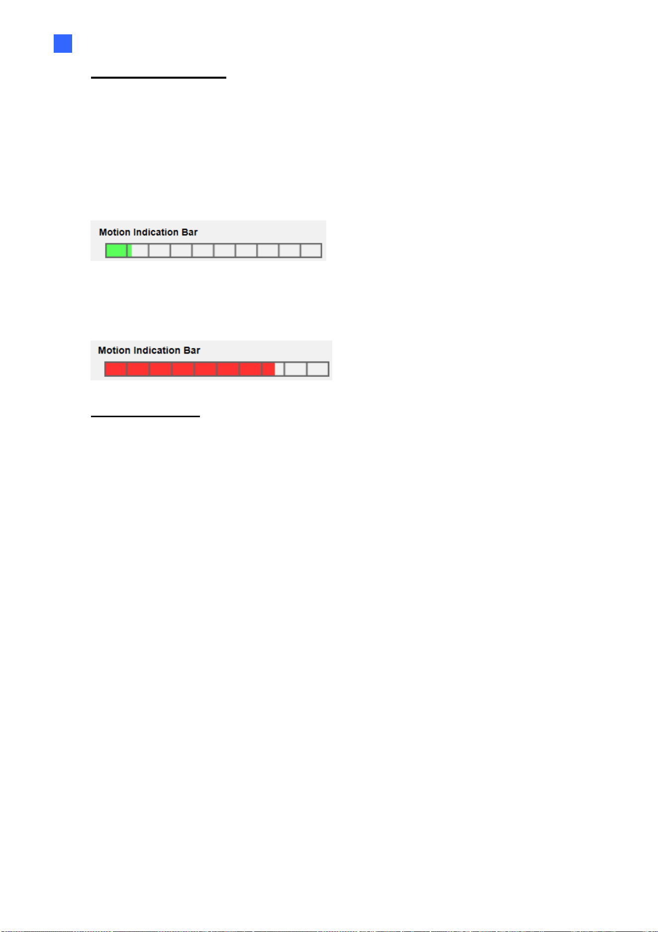
Motion Indication Bar
When Motion Detection function is activated and the motion is detected, the
signals will be displayed on the motion indication bar. The motion indication bar will go
green or red when there is any motion occurrence in the detection region.
Green suggests the occurring motion is detected and does not exceed the
threshold of detection level and sensitivity level. No alarms will be triggered.
Red suggests the ongoing motion exceeds the threshold of detection level and
sensitivity level. The alarm will be triggered.
Triggered Action (Multi-option)
The administrator can specify alarm actions that will take when motion is detected. All
options are listed as follows.
Enable Alarm Output 1/2 (high/low)
Check the item and select the predefined type of alarm output to enable alarm
relay output when motion is detected.
Send Alarm Message by FTP/E-Mail
The administrator can select whether to send an alarm message by FTP and/or
E-mail when motion is detected.
Upload Image by FTP
Select this item and the administrator can assign an FTP site and
configure various parameters. When motion is detected, event images will be
uploaded to the appointed FTP site. Note that to implement this function, one
of the streaming MUST be set as MJPEG; otherwise, this function will be
grayed out and cannot be accessed.
<Pre-trigger buffer> function allows users to check what caused the
trigger. The <Pre-trigger buffer> frame rate could be pre-determined. On
the other hand, <Post-trigger buffer> is for users to upload certain amount of
images after motion event occurs.
38
NOTE: <Pre-trigger buffer> generally ranges from 1 to 20 frames.
However, the range will change accordingly if the frame rate of
MJPEG on Streaming> Video Configuration is 6 or smaller.
Check the box <Continue image upload> to upload the triggered images
during certain time or keep uploading until the trigger is off. Select
<Upload for sec> and enter the duration in the blank. The images of
the duration will be uploaded to FTP when the motion event occurs. The
setting range is from 1 sec. to 99999 sec. Select <Upload during the
trigger active> to make the images keep being uploaded to FTP during
the trigger active until the event stops. Set the Image frequency as the
upload frame rate. The setting range is from 1 to 15 frames per second.
NOTE: Make sure FTP configuration has been completed. Refer
to section FTP for further details.
Upload Image by E-Mail
Select this item and the administrator can assign an E-mail address and
configure various parameters. When motion is detected, event images
will be sent to the appointed E-mail address. Note that to implement this
function, one of the streaming MUST be set as MJPEG; otherwise, this
function will be grayed out and cannot be accessed.
<Pre-trigger buffer> function allows users to check what caused the
trigger. The <Pre-trigger buffer> frame rate could be pre-determined.
On the other hand, <Post-trigger buffer> is for users to upload certain
amount of images after the motion event occurs.
NOTE: <Pre-trigger buffer> generally ranges from 1 to 20 frames.
However, the range will change accordingly if the frame rate of
MJPEG on Streaming> Video Configuration is 6 or smaller.
Check the box <Continue image upload> to upload the triggered images
during certain time or keep uploading until the trigger is off. Select
<Upload for sec> and enter the duration in the blank. The images of
the duration will be uploaded via E-mail when the motion event occurs.
The setting range is from 1 sec. to 99999 sec. Select <Upload during
the trigger active> to make images keep being uploaded via E-mail
during the trigger active until the event stops. Set the Image frequency

Main Tabs
39
2
as the upload frame rate. The setting range is from 1 to 15 frames per
second.
NOTE: Make sure SMTP configuration has been completed.
Refer to section Mail for further details.
Send HTTP Notification
Check this item, select the destination HTTP address, and specify the
parameters for event notifications by <Motion Detection> triggered. When an
alarm is triggered, the notification can be sent to the specified HTTP server.
For instance, if the custom parameter is set as “action=1&group=2”, and the
HTTP server name is “http://192.168.0.1/admin.php”, the notification will be
sent to HTTP server as “http://192.168.0.1/admin.php? action=1&group=2”
when alarm is triggered.
Record Video Clip
Check this item and select a video recording storage type, <SD Card> or
<NAS> (Network-Attached Storage>. The Motion Detection recording will
be stored in SD card or the NAS when motion is detected.
Pre-trigger buffer recording function allows users to check what happened
to cause the trigger. The pre-trigger buffer time range is from 1 sec. to 3 sec.
Select <Upload for sec> to set the recording duration after motion is
triggered. The setting range is from 1 sec. to 99999 sec. Select <Upload
during the trigger active> to record the triggered video until the trigger is off.
NOTE: Please make sure the local recording (with SD card) or
the remote recording (with NAS) is activated so that this function
can be implemented. Refer to section Recording for further
details.

40
File Name
Enter a file name in the blank, e.g. image.jpg. The uploaded image’s file name
format can be set in this section. Please select the one that meets the
requirements.
Add date/time suffix
File name: imageYYMMDD_HHNNSS_XX.jpg
Y: Year, M: Month, D: Day
H: Hour, N: Minute, S: Second
X: Sequence Number
Add sequence number suffix (no maximum value)
File name: imageXXXXXXX.jpg
X: Sequence Number
Add sequence number suffix up to # and then start over
File Name: imageXX.jpg
X: Sequence Number
The file name suffix will end at the number being set. For example, if the
setting is up to “10”, the file name will start from 00, end at 10, and then
start all over again.
Overwrite
The original image in the FTPsite will be overwritten by the new
uploaded file with a static filename.
Save
Click the <Save> button to save the settings.

Main Tabs
41
2
2.2.8.3 Network Failure Detection
The Network Failure Detection setting can be found under this path: System>
Events> Network Failure Detection.
Network Failure Detection allows the camera to ping another IP device (e.g.
NVR, VSS, Video Server, etc.) within the network periodically and generates
some actions in case of network failure occurs, for instance, a Video Server is
somehow disconnected.
Being capable of implementing local recording (through SD card) or remote
recording (via NAS) when network failure happens, the camera can be a backup
recording device for the surveillance system.
Detection Switch
The default setting for the Detection Switch function is <Off>. Enable the
function by selecting <On>. Users can also activate the function according to
the schedule time that is previously set in the <Schedule> setting page. Select
<By schedule> and click the <Please select…> button to choose the
desired schedule from the drop-down menu.
Detection Type
Input the IP device address and the period of ping time to ping. The camera will
ping the IP device every N minute(s). If it fails up to three times, the alarm will
be triggered automatically. The ping time setting range is from 1 to 99 minutes.
Triggered Action (Multi-option)
The administrator can specify alarm actions that will take when network failure
is detected. All options are listed as follows.
Enable Alarm Output 1 /2
Select the item to enable alarm relay output.
Send Alarm Message by FTP/E-Mail
The administrator can select whether to send an alarm message by FTP
and/or E-mail when an alarm is triggered.
Record Video Clip
Check the item and select a video recording storage type, <SD Card> or
<NAS> (Network-Attached Storage). The alarm-triggered recording will
be saved into the SD card.

42
Pre-trigger buffer recording function allows users to check what
happened to cause the trigger. The pre-trigger buffer time range is from
1 sec. to 3 sec. Select <Upload for sec> to set the recording duration
after alarm is triggered. The setting range is from 1 sec. to 99999 sec.
Select <Upload during the trigger active> to record the triggered video
until the trigger is off.
NOTE: Please make sure the local recording (with SD card) or
the remote recording (with NAS) is activated so that this function
can be implemented. Refer to section Recording for further
details.
Save
Click the <Save> button to save all the settings mentioned above.

Main Tabs
43
2
2.2.8.4 Tampering
The Tampering setting can be found under this path: System> Events>
Tampering.
Tampering Alarm function helps the IP camera against tampering, such as
deliberate redirection, blocking, paint spray, and lens cover, etc., through video
analysis and reaction to such events by sending out notifications or uploading
snapshots to the specified destination(s).
Detection of camera tampering is achieved by measuring the differences
between the older frames of video (which are stored in buffers) and more recent
frames.
Tampering Alarm
The default setting for the Tampering Alarm function is <Off>. Enable the
function by selecting <On>. Users can also activate the function according to
the schedule previously set in the <Schedule> setting page. Select <By
schedule> and click <Please select…> to choose the desired schedule from the
drop-down menu.
Tampering Duration
Minimum Tampering Duration is the time for video analysis to determine
whether camera tampering has occurred. Minimum Duration could also be
interpreted as defining the Tampering threshold; longer duration represents
higher threshold. Settable Tampering Duration time range is from 10 to 3600
sec. The Default value is 20 sec.
Triggered Action
The administrator can specify alarm actions that will take when tampering is
detected. All options are listed as follows.
Enable Alarm Output (high/low)
Check the item and select the predefined type of alarm output to
enable alarm output when tampering is detected.
Send Message by FTP/E-Mail
The administrator can select whether to send an alarm message by
FTP and/or E-mail when tampering is detected.
Upload Image by FTP
Select this item and the administrator can assign an FTP site and
configure various parameters. When tampering is detected, event
images will be uploaded to the appointed FTP site. Note that to
implement this function, one of the streaming MUST be set as MJPEG;
otherwise, this function will be grayed out and cannot be accessed.
<Pre-trigger buffer> function allows users to check what caused the
trigger. The <Pre-trigger buffer> frame rate could be pre-determined. On
the other hand, <Post-trigger buffer> is for users to upload certain amount
of images after tampering is triggered.
44
NOTE: <Pre-trigger buffer> generally ranges from 1 to 20
frames. However, the range will change accordingly if the
frame rate of MJPEG on Streaming> Video Configuration is
6 or smaller.
Check the box <Continue image upload> to upload the triggered
images during certain time or keep uploading until the trigger is off.
Select <Upload for __ sec> and enter the duration in the blank. The
images of the duration will be uploaded to FTP when tampering is
triggered. The setting range is from 1 to 99999 sec. Select <Upload
during the trigger active> to make the images keep being upload to
FTP during the trigger active until the tampering stops. Set the Image
frequency as the upload frame rate. The setting range is from 1 to 15
frames.
NOTE: Make sure FTP configuration has been completed.
Refer to section FTP for further details.
Upload Image by E-Mail
Select this item and the administrator can assign an E-mail address
and configure various parameters. When tampering is detected, event
images will be sent to the appointed E-mail address. Note that to
implement this function, one of the streaming MUST be set as MJPEG;
otherwise, this function will be grayed out and cannot be accessed.
<Pre-trigger buffer> function allows users to check what caused the
trigger. The <Pre-trigger buffer> frame rate could be pre-determined. On
the other hand, <Post-trigger buffer> is for users to upload certain amount
of images after tampering occurs.
NOTE: Normally the setting range of the <Pre-trigger buffer>
is 1 to 20 frames. However, the setting range will change
accordingly if the frame rate of MJPEG on the <Video
Configuration> setting page is 6 or smaller.
Check the box <Continue image upload> to upload the triggered
images during certain time or keep uploading until the trigger is off.
Select <Upload for __ sec> and enter the duration in the blank. The
images of the duration will be uploading by E-mail when tampering is
triggered. The setting range is from 1 to 99999 sec. Select <Upload
during the trigger active> to make the images keep being upload to E-
mail during the trigger active until tampering stops. Set the Image
frequency as the upload frame rate. The setting range is from 1 to 20
frames.
NOTE: Make sure SMTP configuration has been completed.
Refer to section Mail
for further details.
Send HTTP Notification
Check this item, select the destination HTTP address, and specify the
parameters for HTTP notifications. When the Tampering Alarm is
triggered, the HTTP notifications can be sent to the specified HTTP
server.

Main Tabs
45
2
For instance, if the custom parameter is set as “action=1&group=2”,
and the HTTP server name is “http://192.168.0.1/admin.php”, the
notification will be sent to HTTP server as
“http://192.168.0.1/admin.php? action=1&group=2” when alarm is
triggered.
Record Video Clip
Check this item and select a video recording storage type, <SD Card>
or <NAS> (Network-Attached Storage). The alarm-triggered recording
will be stored into microSD/SD card or the NAS.
<Pre-trigger buffer> recording function allows users to check what
caused the trigger. The pre-trigger buffer time range is from 1 to 3 sec.
Select <Upload for __ sec> to set the recording duration after
tampering occurs. The setting range is from 1 to 99999 sec. Select
<Upload during the trigger active> to record the triggered video until
the trigger is off.
NOTE: Please make sure the local recording (with
microSD/SD card) or the remote recording (with NAS) is
activated so that this function can be implemented. Refer to
section Recording for further details.
File Name
Enter a file name in the blank, e.g. image.jpg. The uploaded image’s file name
format can be set in this section. Please select the one that meets the
requirements.
Add date/time suffix
File name: imageYYMMDD_HHNNSS_XX.jpg
Y: Year, M: Month, D: Day
H: Hour, N: Minute, S: Second
X: Sequence Number
Add sequence number suffix (no maximum value)
File name: imageXXXXXXX.jpg
X: Sequence Number
Add sequence number suffix up to # and then start over
File Name: imageXX.jpg
X: Sequence Number
The file name suffix will end at the number being set. For example, if
the setting is up to “10”, the file name will start from 00, end at 10, and
then start all over again.
Overwrite
The original image in the FTP site will be overwritten by the new
uploaded file with a static filename.
Save
Click on <Save> to save all the settings mentioned above.

46
2.2.8.5 Periodical Event
The Periodical Event setting can be found under this path: System> Events>
Periodical Event.
With Periodical Event setting, users can set the camera to upload images
periodically to an FTP site or an E-mail address. For example, if the time interval
is set to 60 seconds, the camera will upload images to the FTP site or the E-mail
address every 60 seconds. The images to be uploaded are the images before
and after the triggered moment. Users can define how many images to be
uploaded in the <Triggered Action> section of this setting page.
Periodical Event
The default setting for the Periodical Event function is <Off>. Enable the
function by selecting <On>.
Time Interval
The default value of the time interval is 60 seconds. The setting range of the
time interval is from 60 to 3600 seconds.
Triggered Action
Upload Image by FTP
Select this item and the administrator can assign an FTP site and
configure various parameters. Images will be uploaded to the appointed
FTP site periodically. Note that to implement this function, one of the
streaming MUST be set as MJPEG; otherwise, this function will be
grayed out and cannot be accessed.
The <Pre-trigger buffer> function can define how many images to be
uploaded before the triggered moment. The <Post-trigger buffer>
function can define how many images to be uploaded after the triggered
moment.
NOTE: <Pre-trigger buffer> generally ranges from 1 to 20 frames.
However, the range will change accordingly if the frame rate of
MJPEG on Streaming> Video Configuration is 6 or smaller.
NOTE: Make sure FTP configuration has been completed.
Refer to section FTP of this chapter for further details.
Main Tabs
47
2
Upload Image by E-Mail
Select this item and the administrator can assign an E-mail address and
configure various parameters. Images will be uploaded to the appointed
E-mail address periodically. Note that to implement this function, one of
the streaming MUST be set as MJPEG; otherwise, this function will be
grayed out and cannot be accessed.
The <Pre-trigger buffer> function can define how many images to be
uploaded before the triggered moment. The <Post-trigger buffer>
function can define how many images to be uploaded after the triggered
moment.
NOTE: <Pre-trigger buffer> generally ranges from 1 to 20 frames.
However, the range will change accordingly if the frame rate of
MJPEG on Streaming> Video Configuration is 6 or smaller.
NOTE: Make sure SMTP configuration has been completed.
Refer to section Mail of this chapter for further details.
File Name
Enter a file name in the blank, e.g. image.jpg. The uploaded image’s file name
format can be set in this section. Please select the one that meets the
requirements.
Add date/time suffix
File name: imageYYMMDD_HHNNSS_XX.jpg
Y: Year, M: Month, D: Day
H: Hour, N: Minute, S: Second
X: Sequence Number
Add sequence number suffix (no maximum value)
File name: imageXXXXXXX.jpg
X: Sequence Number
Add sequence number suffix up to # and then start over
File Name: imageXX.jpg
X: Sequence Number

48
The file name suffix will end at the number being set. For example, if the
setting is up to “10”, the file name will start from 00, end at 10, and then start
all over again.
Overwrite
The original image in the FTP site will be overwritten by the new uploaded file
with a static filename.
Save
Click the <Save> button to save all the settings mentioned above.

Main Tabs
49
2
2.2.8.6 Manual Trigger
The Manual Trigger setting can be found under this path: System> Events>
Manual Trigger.
With Manual Trigger setting, the current image(s) or video can be uploaded to
the appointed destination, such as an FTP site or an E-mail address. The
administrator can specify the triggered actions that will take when the users
switch the Manual Trigger button to ON. All options are listed as follows.
Manual Trigger
The default setting for the Manual Trigger function is <Off>. Enable the function
by selecting <On>. After the Manual Trigger function is enabled, click the
Manual Trigger button on the Home page to start uploading data. Click again to
stop uploading.
Triggered Action (Multi-option)
The administrator can specify alarm actions that will take at an alarm
occurrence. All options are listed as follows.
Enable Alarm Output 1/2
Select these items to enable alarm relay outputs.
Send Message by FTP/E-Mail
The administrator can select whether to send an alarm message by FTP
and/or E-mail when an alarm is triggered.
Upload Image by FTP
Select this item and the administrator can assign an FTP site and
configure various parameters. When the alarm is triggered, event
images will be uploaded to the appointed FTP site. Note that to
implement this function, one of the streaming MUST be set as MJPEG;
otherwise, this function will be grayed out and cannot be accessed.
<Pre-trigger buffer> function allows users to check what happened to
cause the trigger. The <Pre-trigger buffer> frame rate could be pre-
determined. On the other hand, <Post-trigger buffer> is for users to
upload certain amount of images after the alarm input is triggered.
50
NOTE: <Pre-trigger buffer> generally ranges from 1 to 20
frames. However, the range will change accordingly if the
frame rate of MJPEG on Streaming> Video Configuration is 6
or smaller.
Check the box <Continue image upload> to upload the triggered images
during certain time or keep uploading until the trigger is off. Select
<Upload for sec> and enter the duration in the blank. The images of the
duration will be uploaded to FTP when the alarm input is triggered. The
setting range is from 1 sec. to 99999 sec. Select <Upload during the trigger
active> to make the images keep being uploaded to FTP during the trigger
active until the alarm is released. Set the Image frequency as the upload
frame rate. The setting range is from 1 to 15 frames per second.
NOTE: Make sure the FTP configuration has been completed.
Refer to section FTP for further details.
Upload Image by E-Mail
Select this item and the administrator can assign an E-mail address and
configure various parameters. When the alarm is triggered, event images
will be sent to the appointed E-mail address. Note that to implement this
function, one of the streaming MUST be set as MJPEG; otherwise, this
function will be grayed out and cannot be accessed.
<Pre-trigger buffer> function allows users to check what happened to
cause the trigger. The <Pre-trigger buffer> frame rate could be pre-
determined. On the other hand, <Post-trigger buffer> is for users to upload
certain amount of images after alarm input is triggered.
NOTE: <Pre-trigger buffer> generally ranges from 1 to 20
frames. However, the range will change accordingly if the
frame rate of MJPEG on Streaming> Video Configuration 6
or smaller.
Check the box <Continue image upload> to upload the triggered images during certain time
or keep uploading until the trigger is off. Select <Upload for sec> and enter the duration
in the blank. The images of the duration will be uploaded via E-mail when the alarm input
is triggered. The setting range is from 1 sec. to 99999 sec. Select <Upload> during the
<trigger active> to make the images keep being uploaded via E-mail during the trigger
active until the alarm is released. Set the Image frequency as the upload frame rate. The
setting range is from 1 to 15 frames per second.
Main Tabs
51
2
NOTE: Make sure SMTP configuration has been completed.
Please refer to section Mail for further details.
PTZ Function
Assign a camera function: Preset, Sequence, Autopan or Cruise, and
specify a Preset Point / Sequence Line / Autopan Path / Cruise Line for
the camera to perform at an alarm occurrence.
NOTE: Please refer to the sections through Preset Programming
to Sequence Line Programming for details of Preset Point /
Cruise Line / Autopan Path / Sequence Line setups.
If the selected function is <Preset>, it is required to enter its dwell time (1
sec. to 256 sec.) in the corresponding field. When the alarm is triggered,
the camera will go to the selected Preset Point and stay there for a
user-defined period of time. As for other function modes, the camera will
keep executing the specified function; to stop the performance, simply
change the camera’s status.
NOTE: The dwell time is only adjustable when <Preset> is
selected. When the dwell time is up, the camera will go back to
its trigger position and recheck the alarm pin status.
Send HTTP notification
Check this item, select the destination HTTP address, and specify the
parameters for event notifications by <Alarm> triggered. When an alarm
is triggered, the notification can be sent to the specified HTTP server.
For instance, if the custom parameter is set as “action=1&group=2”, and
the HTTP server name is “http://192.168.0.1/admin.php”, the notification
will be sent to HTTP server as “http://192.168.0.1/admin.php?
action=1&group=2” when alarm is triggered.
Record Video Clip
Check the item and select a video recording storage type, <SD Card> or
<NAS> (Network-Attached Storage). The alarm-triggered recording will
be saved into the SD card or the NAS.

52
Pre-trigger buffer recording function allows users to check what happened
to cause the trigger. The pre-trigger buffer time range is from 1 sec. to 3 sec.
Select <Upload for sec> to set the recording duration after alarm is triggered.
The setting range is from 1 sec. to 99999 sec. Select <Upload during the
trigger active> to record the triggered video until the trigger is off.
NOTE: Please make sure the local recording (with SD / SDHC
card) or the remote recording (with NAS) is activated so that this
function can be implemented. Refer to section Recording for
further details.
File Name
Enter a file name in the File name field, e.g. image.jpg. The uploaded image’s file
name format can be set in this section. Please select the one that meets the
requirements.
Add date/time suffix
File name: imageYYMMDD_HHNNSS_XX.jpg Y:
Year, M: Month, D: Day
H: Hour, N: Minute, S: Second X:
Sequence Number
Add sequence number suffix (no maximum value)
File name: imageXXXXXXX.jpg X:
Sequence Number
Add sequence number suffix up to # and then start over
File Name: imageXX.jpg X:
Sequence Number
The file name suffix will end at the number being set. For example, if the
setting is up to “10”, the file name will start from 00, end at 10, and then start
all over again.
Overwrite
The original image in the FTP site will be overwritten by the new uploaded file
with a static filename.
Save
Click the <Save> button to save all the settings mentioned above.

Main Tabs
53
2
2.2.8.7 Audio Detection
The Audio Detection setting can be found under this path: System> Events>
Audio Detection.
Audio Detection function allows the camera to detect audio and trigger alarms
when audio volume in the detected area reaches / exceeds the determined
sensitivity threshold value.
NOTE: Audio Detection function is only available for models
equipped with Audio I/O function.
Audio Detection
In Audio Detection Setting, the default setting for the Audio Detection function is
<Off>. Enable the function by selecting <On>.
Audio Detection Setting
Users could adjust various parameters of Audio Detection in this section.
Detection level [1-100]:
The item is to set detection level for each sampling volume; the smaller
the value, the more sensitive it is. The default level is 10.
Time interval (sec) [0-7200]:
The value is the interval between each detected audio. The default
interval is 10.
Triggered Action (Multi-option)
The administrator can specify alarm actions that will take when audio is
detected. All options are listed as follows.
Enable Alarm Output 1/2
Select these items to enable alarm relay outputs.
Send Alarm Message by FTP/E-Mail
The administrator can select whether to send an alarm message by FTP
and/or E-mail when audio is detected.
54
Upload Image by FTP
Select this item and the administrator can assign an FTP site and
configure various parameters. When audio is detected, event images will
be uploaded to the appointed FTP site. Note that to implement this function,
one of the streaming MUST be set as MJPEG; otherwise, this function will be
grayed out and cannot be accessed.
<Pre-trigger buffer> function allows users to check what happened to cause
the trigger. The <Pre-trigger buffer> frame rate could be pre-determined.
On the other hand, <Post-trigger buffer> is for users to upload certain amount
of images after audio event occurs.
NOTE: <Pre-trigger buffer> generally ranges from 1 to 20
frames. However, the range will change accordingly if the
frame rate of MJPEG on Streaming> Video Configuration 6 or
smaller.
Check the box <Continue image upload> to upload the triggered images
during certain time or keep uploading until the trigger is off. Select
<Upload for sec> and enter the duration in the blank. The images of the
duration will be uploaded to FTP when the audio event occurs. The setting
range is from 1 sec. to 99999 sec. Select <Upload during the trigger
active> to make the images keep being uploaded to FTP during the trigger
active until the event stops. Set the Image frequency as the upload frame
rate. The setting range is from 1 to 15 frames per second.
NOTE: Make sure FTP configuration has been completed. Refer
to section FTP for further details.
Upload Image by E-Mail
Select this item and the administrator can assign an E-mail address and
configure various parameters. When audio is detected, event images will
be sent to the appointed E-mail address. Note that to implement this function,
one of the streaming MUST be set as MJPEG; otherwise, this function will be
grayed out and cannot be accessed.
<Pre-trigger buffer> function allows users to check what happened to
cause the trigger. The <Pre-trigger buffer> frame rate could be pre-
determined. On the other hand, <Post-trigger buffer> is for users to upload
certain amount of images after the audio event occurs.

Main Tabs
55
2
NOTE: <Pre-trigger buffer> generally ranges from 1 to 20 frames.
However, the range will change accordingly if the frame rate of
MJPEG on Streaming> Video Configuration 6 or smaller.
Check the box <Continue image upload> to upload the triggered images
during certain time or keep uploading until the trigger is off. Select
<Upload for sec> and enter the duration in the blank. The images of
the duration will be uploaded via E-mail when the audio event occurs.
The setting range is from 1 sec to 99999 sec. Select <Upload during the
trigger active> to make the images keep being uploaded via E-mail
during the trigger active until the event stops. Set the Image frequency
as the upload frame rate. The setting range is from 1 frame to 15 frames
per second.
NOTE: Make sure SMTP configuration has been completed.
Refer to section Mail for further details.
Send HTTP Notification
Check this item, select the destination HTTP address, and specify the
parameters for event notifications by <Audio Detection> triggered. When
an alarm is triggered, the notification can be sent to the specified HTTP
server.
For instance, if the custom parameter is set as “action=1&group=2”, and
the HTTP server name is “http://192.168.0.1/admin.php”, the notification
will be sent to HTTP server as “http://192.168.0.1/admin.php?
action=1&group=2” when alarm is triggered.
Record Video Clip
Check this item and select a video recording storage type, <SD Card> or
<NAS> (Network-Attached Storage>. The Audio Detection recording will
be stored in SD card or the NAS when audio is detected.
Pre-trigger buffer recording function allows users to check what
happened to cause the trigger. The pre-trigger buffer time range is from
1 sec. to 3 sec. Select <Upload for sec> to set the recording duration
after audio is triggered. The setting range is from 1 sec to 99999 sec.
Select <Upload during the trigger active> to record the triggered video
until the trigger is off.

56
File Name
NOTE: Please make sure the local recording (with SD card) or
the remote recording (with NAS) is activated so that this function
can be implemented. Refer to section Recording for further
details.
Enter a file name in the blank, e.g. image.jpg. The uploaded image’s file name
format can be set in this section. Please select the one that meets the
requirements.
Add date/time suffix
File name: imageYYMMDD_HHNNSS_XX.jpg
Y: Year, M: Month, D: Day
H: Hour, N: Minute, S: Second
X: Sequence Number
Add sequence number suffix (no maximum value)
File name: imageXXXXXXX.jpg
X: Sequence Number
Add sequence number suffix up to # and then start over
File Name: imageXX.jpg
X: Sequence Number
The file name suffix will end at the number being set. For example, if the
setting is up to “10”, the file name will start from 00, end at 10, and then
start all over again.
Overwrite
The original image in the FTP site will be overwritten by the new
uploaded file with a static filename.
Save
Please click the <Save> button to save all the Audio Detection settings
mentioned above.
Main Tabs
57
2
2.2.9
Storage Management
The Storage Management setting can be found under this path: System>
Storage Management.
Click the <Storage Management> category, there will be a drop-down menu
with tabs including <SD Card> and <Network Share>.
2.2.9.1 SD Card
The SD Card setting can be found under this path: System> Storage
Management> SD Card.
Users can implement local recording to the SD card up to 128GB. This page
shows the capacity information of the SD card and a recording list with all the
recording files saved on the memory card. Users can also format the SD card
and implement automatic recording cleanup through the setting page.
To implement SD card recording, please go to the <Recording> page (refer to
section Recording) for activation.
NOTE: Please format the SD card when using it for the first time.
Formatting will also be required when a memory card is being used on
one camera and later transferred to another camera with different
software platform.
NOTE: It is not recommended to record with the SD card for 24/7
continuously, as it may not be able to support long term continuous data
read/write. Please contact the manufacturer of the SD card for
information regarding the reliability and the life expectancy.
Device Information
When users insert the SD card, the card information such as the memory
capacity and status will be shown at the <Device Information> section.
Recording Source
Select a video stream to set as the recording source. The default format of the
video stream is <H.264-1>. Select a preferred stream from the drop-down list
and click the <Save> button to apply the setting.

58
Device Setting
Click the <Format> button to format the memory card. Two filesystems are
provided, <vfat (default)> and <ext4 (recommended)>. It is recommended to select
<ext4> as the filesystem of the memory card for steady and better
performances.
Disk Cleanup Setting
Check <Enable automatic disk cleanup> and specify time <1~999 day(s) or 1~142
week(s)> and storage limits <1~99% full> to configure disk cleanup settings. Click
the <Save> button to save the settings.
Recording List
Each video file on the SD card will be listed in the Recording list. The maximum file
size is 60 MB/per file.
When the recording mode is set as <Always> (consecutive recording) and the SD
card recording is also allowed to be enabled by events triggered, once events
occur, the system will immediately implement events recording to the memory
card. After the recording of the events are finished, the camera will return to the
regular recording mode.
Remove
To remove a file, select the file first, and then click the <Remove> button.
Sort
Click the <Sort> button, and the files in the Recording list will be listed in name
and date order.
The capital letter A / M / N / R / V / U in the very beginning of name
denotes the sort of the recording as below.
Initial Recording Type Initial Recording Type
A
Alarm
R
Regular Recording
M
Motion
V
Manual Trigger
N
Network Failure
U
Audio Detection
Download
To open / download a video clip, select the file first, and then click the
<download> button below the Recording list field. The selected file window
will pop up. Click the AVI file to directly play the video in the player or
download it to a specified location.

Main Tabs
59
2
2.2.9.2 Network Share (NAS)
The Network Share setting can be found under this path: System> Storage
Management> Network Share.
Users can store the recording videos to a network share folder, or NAS
(Network-Attached Storage). A NAS device is used for data storage and data
sharing via network. This page displays the capacity information of the network
device and a recording list with all the recording files saved on the network
device. Users can also format the NAS and implement automatic recording
cleanup through the setting page.
Device information
When a NAS is successfully installed, the device information such as the
memory capacity and status will be shown at the <Device Information> section.
Storage setting
The administrator can set the camera to send the alarm messages to a specific
NAS site when an alarm is triggered. Enter the network device details, which
include host (the IP of the NAS), share (the folder name of the NAS), user name,
and password, in the fields.
Click the <Save> button when finished.
Storage Tools
Click the <Format> button to format the NAS.
Recording Source
Select a video stream to set as the recording source. The default format of the
video stream is <Stream 1>. Select a preferred stream from the drop-down list
and click the <Save> button to apply the setting.
Disk cleanup setting
Check <Enable automatic disk cleanup> and specify the time <1~99 day(s) or
1~142 week(s)> and storage limits <1~99% full> to configure disk cleanup
settings. Click the <Save> button to confirm the settings.
60
Recording List
Each video file on the Network Share will be listed in the Recording list. The
maximum file size is 60 MB/per file.
When the recording mode is set as <Always> (consecutive recording) and the
NAS recording is also allowed to be enabled by events triggered, once events
occur, the system will immediately implement events recording to the memory
card. After the recording of the events are finished, the camera will return to the
regular recording mode.
Remove
To remove a file, select the file first, and then click the <Remove> button.
Sort
Click the <Sort> button, and the files in the Recording list will be listed in
name and date order.
The capital letter A / M / N / R / V / U in the very beginning of name
denotes the sort of the recording as below.
Initial Recording Type Initial Recording Type
A
Alarm
R
Regular Recording
M
Motion
V
Manual Trigger
N
Network Failure
U
Audio Detection
Download
To open / download a video clip, select the file first, and then click the
<download> button below the Recording list field. The selected file
window will pop up. Click the AVI file to directly play the video in the
player or download it to a specified location.
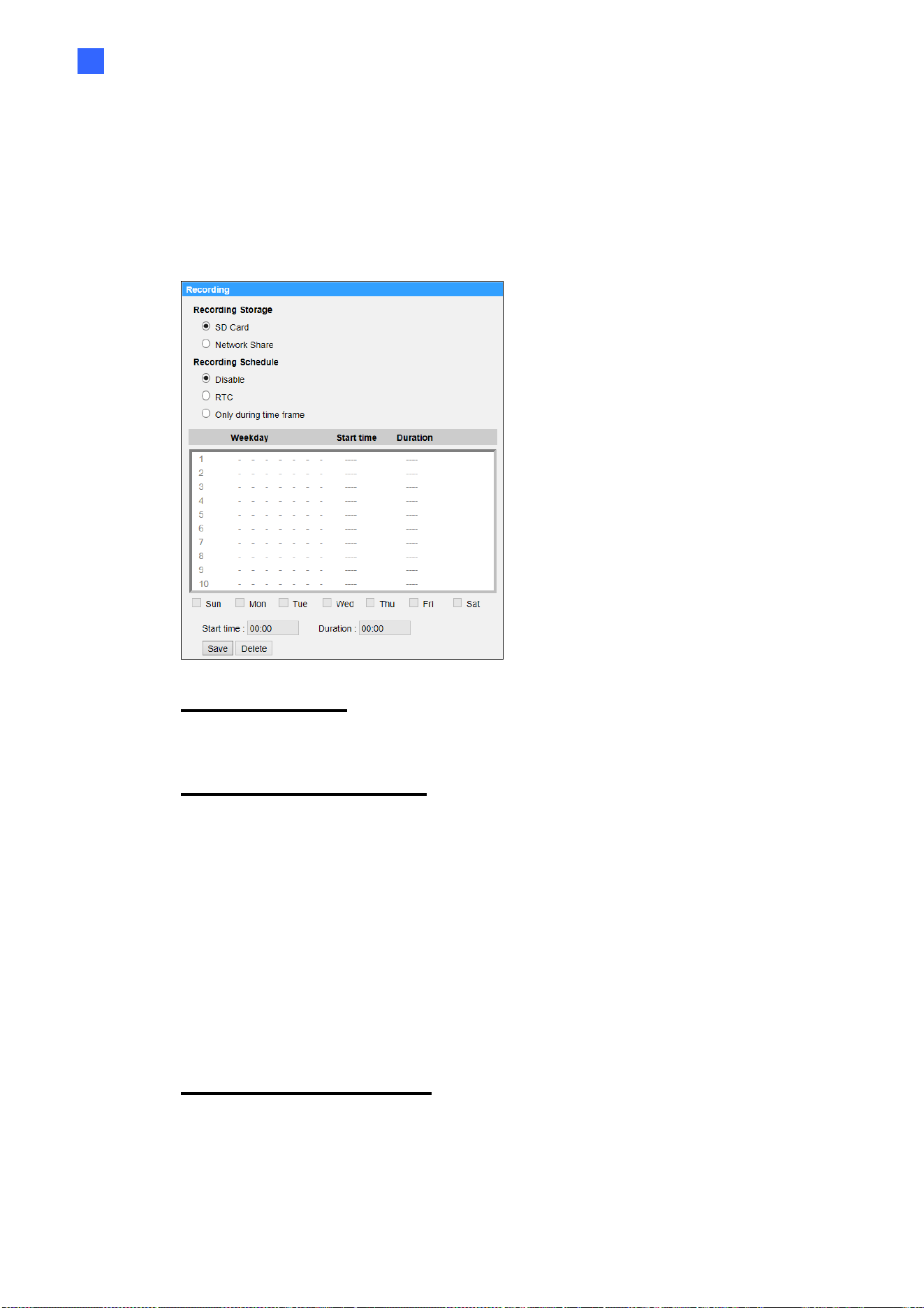
Main Tabs
61
2
2.2.10
Recording
The Recording setting can be found under this path: System> Recording.
In the <Recording> setting page, users can specify the recording schedule that
fits the present surveillance requirement.
Recording Storage
Select a recording storage type, <SD Card> or <Network Share>.
Enable Recording Schedule
Two types of schedule mode are offered: <Always> and <Only during time
frame>. Users can select <Always> to activate SD Card or Network Share
Recording all the time. Or, select a set of schedule from the time frame blank,
check specific weekdays and setup the start time (hour:minute) and time period
(hour:minute) to activate the recording at certain time frames. The setting range
for the duration time is from 00:00 to 168:59. Click the <Save> button to save
the setup.
To delete a schedule, select one from the list, and click the <Delete> button.
Disable Recording Schedule
Select <Disable> to terminate the recording function.
Click the <Save> button when finished.
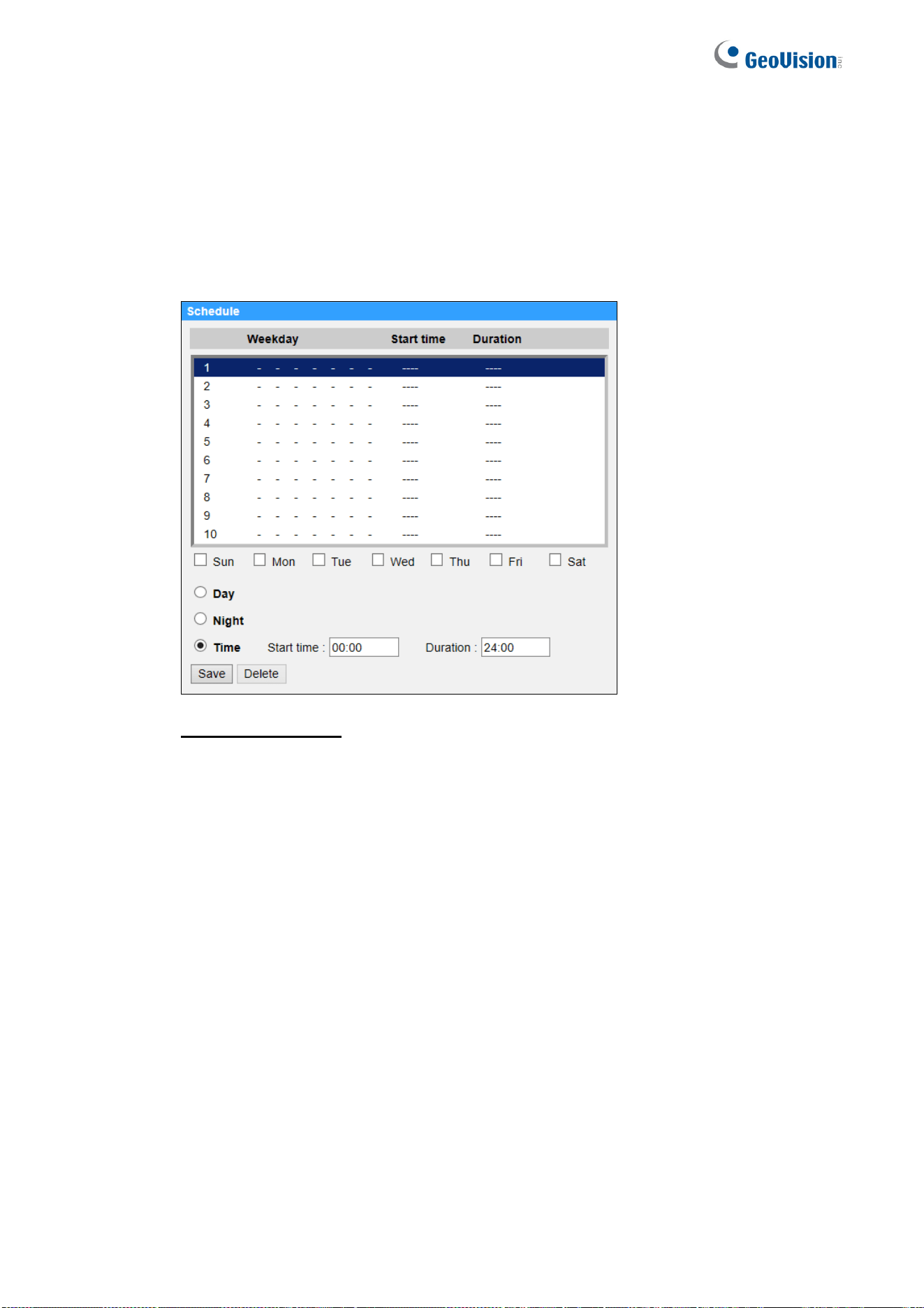
62
2.2.11
Schedule
The Schedule setting can be found under this path: System> Schedule.
This function allows users to setup schedules for features including: <Alarm
Switch>, <Motion Detection> and <Network Failure Detection>. The function
supports up to 10 sets of time frames in the time frame list.
Setting Schedules
Step 1. Select a time frame from the time frame list.
Step 2. Check the weekday boxes below to choose the specific weekdays.
Main Tabs
63
2
Step 3. Select a time mode, Day, Night or Time. Under Time mode, specify
the start time (hour:minute) and the time duration (hour:minute) to
activate the schedule triggered features. The setting range for the
time duration is from 00:00 to 168:59.
Step 4. Click the <Save> button to save the setup. Alternatively, click the
<Delete> button to delete a chosen time frame.
Time Mode
Day
The camera profile will be loaded when IR cut filter is on.
Night
The camera profile will be loaded when IR cut filter is off.
Time
This indicates the start time and the time duration for the schedule.
NOTE: Users MUST select <By schedule> under each feature setting
page to enable the schedule function.
2.2.12
File Location (Snapshots and Web Recording)
The File Location setting can be found under this path: System> File Location.
Users can specify a storage location on the PC or in the hard drive for the
snapshots and the live video recordings. The default setting is:
C:\ProgramData\Geovision\. Once the setting is confirmed, click the <Save>
button, and all the snapshots and the web recordings will be saved in the
designate location.
NOTE: Make sure the selected file path contains valid characters such
as letters and numbers.
NOTE: With Windows 7 operating system or above, to implement the
Snapshot and Web Recording functions, users must run IE as
administrator. To run IE as administrator, right click the IE browser icon
and select “Run As Administrator” to launch IE.

64
2.2.13
View Information
The View Information function can be found under this path: System> View
Information.
Click the category: <View Information>, there will be a drop-down menu with
tabs including <Log File>, <User Information>, and <Parameters>.
2.2.13.1 Log File
The Log File function can be found under this path: System> View
Information> Log File.
Click the tab to view the system log file. The camera keeps a record of the
system’s behavior and information related to the camera. These log data can be
exported for future use. Click the <generate syslog> button and the Save File As
dialog window will pop up. The default file name is named after the model name
and the MAC address as “Model Name-MAC-log.tgz”. Select the file destination
and click the <Save> button to export the log data.
NOTE: “Save File As” dialog window may not show up immediately for
the camera needs some time to process the log data.
2.2.13.2 User Information
The User Information function can be found under this path: System> View
Information> User Information.
The administrator can view the login information and privileges of each added
user (refer to section Security).
User: 1:1:0:1
1:1:0:1= I/O access: Camera control: Talk: Listen (refer to section Security)
“1” denotes this user is allowed to access the function; whereas “0” suggest no
access for this user is allowed.
2.2.13.3 Parameters
The Parameters function can be found under this path: System> View
Information> Parameter.
Main Tabs
65
2
Click this item to view the parameter settings of the entire system, such as
Camera Settings, Mask Information and Network Information.
2.2.13.4 Open Source Software Licenses
The Open Source Software Licenses function can be found under this path:
System> View Information> Open Source Software Licenses.
2.2.14
Factory Default
The Factory Default setting can be found under this path: System> Factory
Default.
Users can follow the instructions on this page to reset the camera to factory
default settings if needed.
Full Restore
Click the <Full Restore> button to recall the factory default settings. The camera
system will restart in 30 seconds. The IP address will be restored to default.
After the camera system is restarted, reconnect the camera using the default IP
address. The default IP address is 192.168.0.10.
Partial Restore
Click the <Partial Restore> button to recall the factory default settings
(excluding network settings/User settings). The camera system will restart in
30 seconds. Refresh the browser page after the camera system is restarted.
NOTE: The IP address will not be restored to default.
Reboot
Click the <Reboot> button and the camera system will restart without changing
the current settings. Refresh the browser page after the camera system is
restarted.
2.2.15
Software Version (Firmware Version)
The Software Version can be found under this path: System> Software
Version.
The software version page displays the current software version, and the
pan/tilt/zoom mcu version.
66
2.2.16
Software Upgrade (Firmware Upgrade)
The Software Upgrade setting can be found under this path: System> Software
Upgrade.
NOTE: Make sure the upgrade software file is available before carrying
out software upgrade.
The procedure of software upgrade is as below.
Step 1. Click the <Start> button in Windows and locate the upgrade file, for
example, “ulmage_userland”.
NOTE: Do not change the name of the upgrade file, or the
system will fail to find the file.
Step 2. Pick a file type from the drop-down list. In this case, select
“ulmage+userland.img”.
Step 3. Click the <Upgrade> button. Then the system will prepare to start the
software upgrade. Subsequently, an upgrade status bar will be
displayed on the page to show the current upgrade process. After the
upgrade process is finished, the viewer will return to the <Home> page.
If the prompt to reinstall the GV-CameraViewer appears, follow the steps below.
Step 1. Click the <Start> button in Windows and activate the <Control Panel>.
In the appeared window, double click the <Add or Remove
Programs> button. A window with the <Currently install programs> list
will popup. In the list, select <Camera Viewer> and click the
<Remove> button to uninstall the existing Viewer.
Step 2. Open a new web browser and re-login the camera. Users will be
prompted to download the Camera Viewer. Once the Camera Viewer is
downloaded and installed, the live video will be available.

Main Tabs
67
2
2.2.17
Maintenance
The Maintenance setting can be found under this path: System> Maintenance.
Users can export configuration files to a specified location and retrieve data by
uploading the configuration file to the camera.
Export Files
Users can save the system settings by exporting a configuration file (.bin) to a
specified location for future use. Click the <Export> button, and the popup File
Download window will come out. Click the <Save> button and specify a desired
location for saving the configuration file.
Upload Files
To upload a configuration file to the camera, click the <Browse> button to select
the configuration file and then click the <Upload> button for uploading.
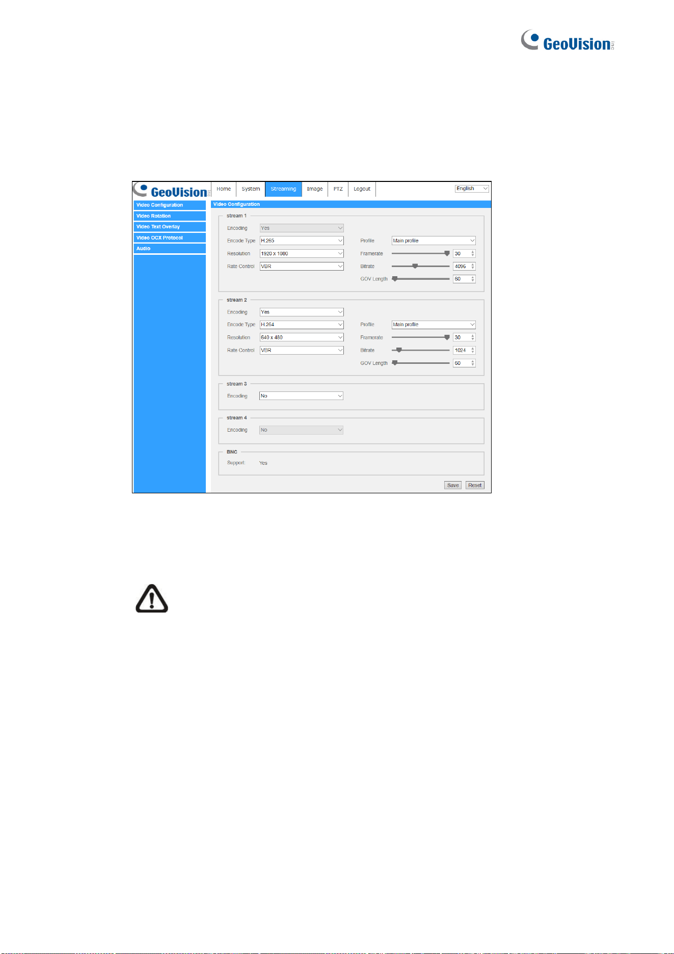
68
2.3 Streaming
Under the tab <Streaming>, there are categories including: <Video Format>,
<Video Compression>, <Video OCX Protocol>, <Video Frame Rate>, and
<Audio>.
In the Streaming submenu, the administrator can configure specific video
resolution, video compression mode, video protocol, audio transmission mode,
etc. Further details of these settings will be specified in the following sections.
NOTE: Only administrator can access the <Streaming> setting page.

Main Tabs
69
2
2.3.1
Video Configuration (Video Format & Resolution)
The Video Configuration setting can be found under this path: Streaming>
Video Configuration.
Encoding
Select <Yes> from the drop-down menu to enable Stream 2~Stream 4 encoding.
Or select <No> to disable the streaming encoding.
Encode Type
The available video resolution formats include H.265, H.264 and MJPEG. Users
can select the preferred encode type from the drop-down menu.
Resolution
Video format and resolution combination will vary by user’s configuration.
Rate Control
There are three kinds of H.265/H.264 bitrate modes provided: CBR (Constant
Bit Rate), VBR (Variable Bit Rate) and LBR (Low Bit Rate).
CBR
The sent-out video bitrate will be fixed and consistent to maintain the
bandwidth.
VBR
Video bitrate varies according to the activity of the monitoring
environment to achieve better image quality.
70
LBR
LBR keeps low bitrate and ensures superior image quality. To implement LBR
control, setup the compression level and dynamic GOV for each streaming
accordingly beforehand.
- Compression
Based on the current application area and streaming bitrate, select the
most suitable compression level, high/mid/low.
Set <High>, and bitrate will vastly be reduced; however, image quality may
be degraded at the same time.
Set <Low>, and bitrate will stably keep low while image quality
remains high.
- Dynamic GOV
According to the amount of motion in the application area, the GOV
length of the video will be adjusted dynamically to reduce more
bitrate, especially for scenes with minor changes. The length of
Dynamic GOV is from <GOV Length> to <Max. GOV> (4094).
Select <Enabled> and set <Max. GOV>. Then, click the <Save>
button to activate the setting.
If there is small or zero activity in the scene, set <Max. GOV> larger, the
GOV length will be longer, resulting in lower bitrate and bandwidth.
If there are constant dynamic changes in the scene, it is suggested just
adjust <GOV Length> and disable <Dynamic GOV>.
Click the <Save> button to confirm the setting.
Profile
Users can set H.265/H.264 Profile to <High Profile> or <Main Profile> according to its
compression needs. With the same bit rate, the higher the compression ratio, the
better the image quality is. The default setting is <Main Profile>.
NOTE: Please make sure the higher compression ratio is supported by the
system before setup.

Main Tabs
71
2
Framerate
Video framerate is for setting the frames per second (fps) if necessary. The
default setting of Stream 1 is 30 fps (NTSC) or 25 fps (PAL). The maximum
framerate range of each stream will change according to the selected video
resolution.
NOTE: Low framerate will decrease video smoothness.
Bitrate
The default H.265/H.264 bitrate for Stream 1 is 4096 kbit/s; for Stream 2 is
1024 kbit/s; for Stream 3/ Stream 4 is 2048 kbit/s. The setting range is from
64 to 10240 kbps, and the total bit rate should not exceed 26624 kbps.
GOV Length
Users can set the GOV length to determine the frame structure (I-frames and
P-frames) in a video stream to save bandwidth. Less bandwidth is needed if the
GOV length is set to a high value. However, the shorter the GOV length, the
better the video quality is. The default setting for Stream 1/2/3/4 is 60. The
setting range of the GOV length is from 1 to 4094.
Q (Quality) Factor (MJPEG Only)
The default setting of MJPEG Q factor is 35; the setting range is from 1 to 70.
Click the <Save> button to confirm the setting or click the <Reset> button to
return to the previous settings.
2.3.2
Video Rotation
Rotate Function
Users can change video display type if necessary. Selectable video rotate types
include Mirror video and 90/180/270 degree clockwise rotate. Refer to the
following descriptions for the different video rotate type.
Mirror
Select <yes> from the drop-down menu, and the image will be rotated
horizontally.
Rotate Type
Users can choose 0, 90, 180, or 270 degree from the drop-down menu
to rotate the image.
Click the <Save> button to confirm the setting.

72
2.3.3
Video Text Overlay
Users can select the items to display data, including date / time / text string /
subtitle / image on the live video pane.
Overlay Type
Users can select at most three items out of four options including date & time /
text string / subtitle / image to display on the live video pane.
Include date & time
Check the box to enable date & time display on the Live Video Pane.
Users can choose to display date, time, or date & time from the drop-
down menu, and decide the string align position (left / right).
Include text string
Check the box to enable text string display on the Live Video Pane. Type
the text to display in the entry field and decide the string align position
(left / right). The maximum length of the text string is 25 alphanumeric
characters.
Include subtitle
Check the box to enable subtitle display on the Live Video Pane. Type
the text to display in the entry field and decide the string align position
(left / right). Users can set at most 5 subtitles, and the maximum length
of each subtitle is 16 alphanumeric characters.
Include Image
Check the box to enable image display on the Live Video Pane. Select
an alignment position (left /right) for the image from the drop-down list.
(To upload an image for display, see Image Overlay Setting below
Include azimuth
Check the box to enable azimuth display on the Live Video Pane and set
the azimuth alignment position. Azimuth shows the pan/tilt degree and
the shooting position of the camera, such as NE 050/00 (“NE”: the
shooting position of the camera; “050”: pan degree, “00”: tilt degree.)
Include Zoom Ratio
Check the box to enable zoom ratio display on the Live Video Pane. Select
an alignment position (left/right) for the ratio display from the drop-down list.

Main Tabs
73
2
When any Overlay Type item is selected, a Video Text Overlay Window will show
up. Move the mouse cursor to the center of the window, click and drag the window
to change the display position. When it is done, click the <Set> button to confirm
the Text Overlay setting.
Text Overlay Setting
Users can choose the Text Overlay Color (black, white, yellow, red, green, blue,
cyan, or magenta) and Text Overlay Size (small, medium, or large) of the
display date & time / text string / subtitle.
Click the <Set> button to confirm the setting.
Image Overlay Setting
Users can upload an image and set its transparency to display on the live video
pane. The setting range of image transparency is from 0 to 255; the lower the
value, the more transparent it is. Users must save the image as an 8-bit BMP
file; the length should be the multiple of 32, and the width should be the multiple
of 4. The maximum resolution of the image should not exceed 32768 pixels.
Click the <Set> button and the <Upload> button to confirm the setting.

74
2.3.4
Video ROI Encoding
The Video ROI Encoding setting can be found under this path: Streaming>
Video ROI Encoding.
Video ROI Encoding is to set the compression of the selected zone within ROI
for better performances; at most three zones can be set in the interested region.
However, this function does NOT support MJPEG video format.
Select a video stream from <Video Stream>.
Select <Enable> from <ROI Encoding> to implement ROI Encoding.
Click on <Add>, click and drag the center of the window to move it to the
desired location; click and drag the edge of the window outward / inward to
resize the window.
Note that the total size of the three windows CANNOT be larger than the half
size of the ROI. When exceeds, a warning window will pop up.
Choose the quality of the setting zone from <Quality>.
The higher the value, the better the image quality (higher bitrate) of the setting
zone will be. On the contrary, the lower the value, the lower the image quality
(lower bitrate) of the selected area will be.
Click on <Save> to apply the setting.
2.3.5
Video OCX Protocol
The Video OCX Protocol setting can be found under this path: Streaming>
Video OCX Protocol.
In the <Video OCX protocol> setting page, the administrator can select RTP
over UDP, RTP over RTSP(TCP), RTSP over HTTP or MJPEG over HTTP, for
streaming media over the network. In the case of multicast networking, users
can select the Multicast mode. Click the <Save> button to confirm the setting.
Video OCX protocol setting options include:
RTP over UDP / RTP over RTSP(TCP) / RTSP over HTTP / MJPEG
over HTTP
Multicast Mode
Enter all required data, including <Multicast IP address>, <Multicast
H.264-1 / H.264-2 / H.264-3 / H.264-4 Video Port>, <Multicast MJPEG
Video Port>, <Multicast Audio Port> and <Multicast TTL> into each
blank.
Click the <Save> button to confirm the setting.

Main Tabs
75
2
2.3.6
Video Mask
The Video Mask setting can be found under this path: Streaming> Video Mask.
Active Mask Function
Add a Mask
Check a Video Mask checkbox, and a red frame will come out in the Live Video
pane. Use the mouse to drag and drop to adjust the mask’s size and place it on
the target zone. At most 5 video masks can be set.
NOTE: It is suggested to set the Video Mask slightly bigger than the object.
Cancel a Mask
Un-check the Video Mask checkbox meant to be deleted; the mask will
disappear from the Live Video pane instantly.
Mask Setting
Mask color
The selections of Mask color include black, white, yellow, red, green, blue, cyan,
and magenta. Click on <Save> to confirm the setting.

76
2.3.7
Audio (Audio Mode and Bit Rate Settings)
The Audio Mode setting can be found under this path: Streaming> Audio.
In this page, the administrator can adjust the sound transmission mode, the
audio gain levels and the audio bit rate. Setting for enabling sound recording to
the SD card is also available.
Transmission Mode
Full-duplex (Talk and Listen simultaneously)
In the Full-duplex mode, the local and remote sites can communicate
with each other simultaneously, i.e. both sites can speak and listen to
the other side at the same time.
Half-duplex (Talk or Listen, not at the same time)
In the Half-duplex mode, the local / remote site can only talk or listen to
the other site at a time.
Simplex (Talk only)
In the Talk only Simplex mode, the local / remote site can only talk to the
other site.
Simplex (Listen only)
In the Listen only Simplex mode, the local / remote site can only listen to
the other site.
Disable
Select the item to turn off the audio transmission function.
Server Gain Setting
Set the audio input / output gain levels for the sound amplification. The audio
input gain value is adjustable from 1 to 10. The audio output gain value is
adjustable from 1 to 6. To turn off the sound, set the audio gain to “Mute”.
Bit Rate
Be default, the Bit Rate is uLAW (64 kbps). Click the <Save> button to confirm
the setting.
Recording to Storage
Select <Enable> from the drop-down menu to enable audio recording with
videos into the SD card or the NAS.
NOTE: If the chosen bit rate is not compatible with the player, there will
only be noise instead of audio during playback.
Click the <Save> button to confirm the setting.
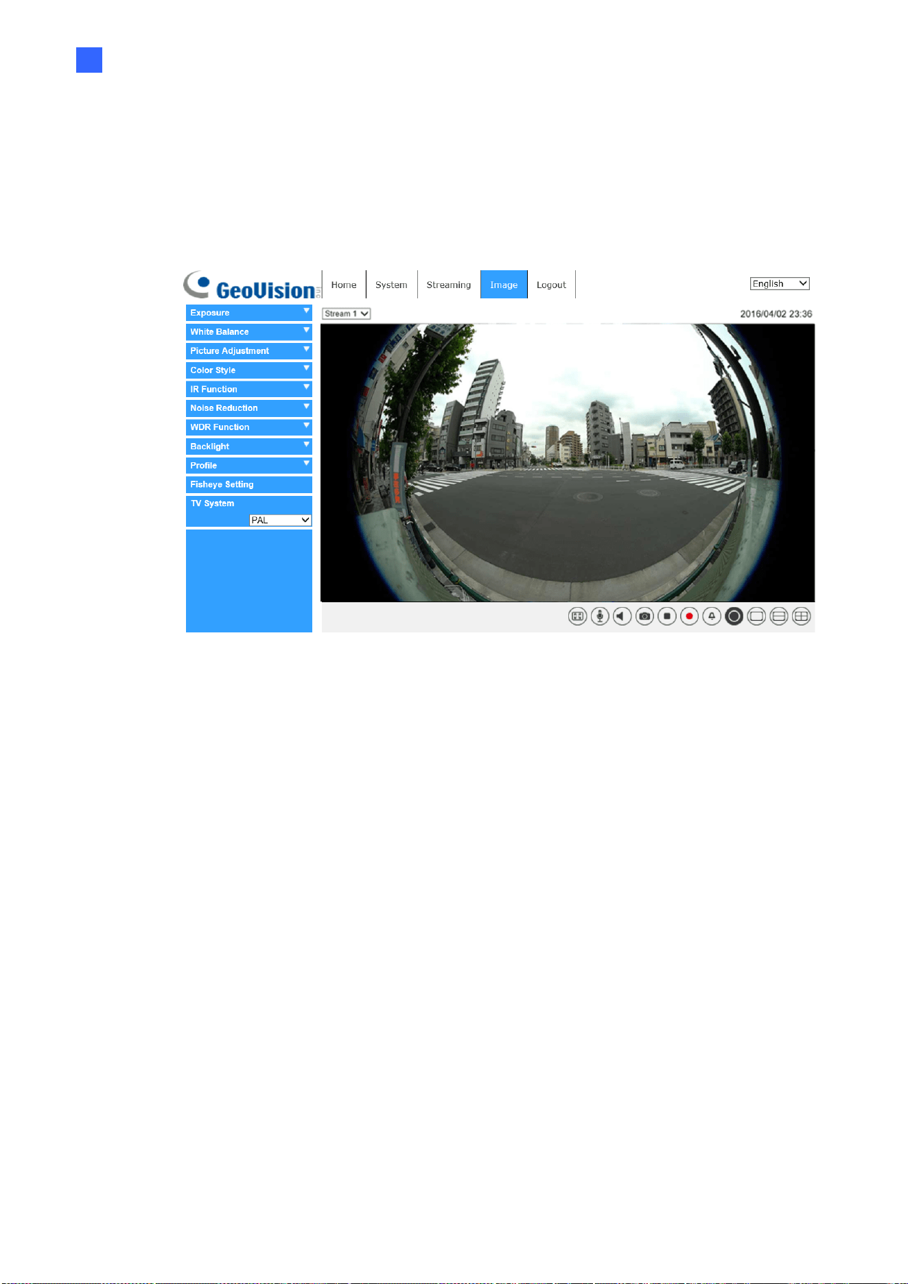
Main Tabs
77
2
2.4 Image
Under the tab <Image>, there are categories including: <Exposure>, <White
Balance>, <Picture Adjustment>, < Color Style> , <IR Function>, <Noise
Reduction>, <WDR Function>, <Image Stabilizer>, <Digital Zoom>, <Profile>,
<Fisheye Setting>, and <TV System>.
78
2.4.1
Exposure
The Exposure setting can be found under this path: Image > Exposure.
In the <Image-Exposure> setting page, users can select either the <Full Auto>
mode or adjust the parameter of the P-Iris Priority / Iris Priority / Shutter Priority
mode for optimized video output in accordance with the operating environment.
Auto Mode
⚫ Window Setting
Select <On> to enable the function for specifying a region of interest for
exposure adjustment on the live view. Adjust the size of the area by
dragging its corners or edges. Once done, click to apply.
⚫ AE Priority
Select <Image Quality> to reduce the frame rate to enhance the image
quality. Select <Realtime> for real-time images with increased frame
rate.
NOTE: Higher frame rates may cause more image noises.
⚫ Night Mode Priority
<Normal> is set by default for the camera to automatically adjust its
exposure value based on the environment lighting. Select <High Light
Detail> to make the exposed object look clearer for low lux surveillance.
⚫ Max Gain
This item is for users to set the maximum limit of gain. The Max Gain
ranges from 0 to 45, or select <Off> to disable the function. The
default setting is 45.
NOTE: Higher max gain may cause more image noises.
⚫ Auto Shutter Mode
In this mode, the camera will automatically adjust the shutter speed and
the iris size according to the light intensity. The minimum shutter
speed can be set from 1/500 to 1 sec. (NTSC) or 1/425 to 1/1.5 sec.
(PAL).
Manual Mode
In this mode, users can change the Shutter Speed, Gain, AE Priority, and Night
Mode Priority manually. The shutter speed range is from 1/10000 sec. to 1 sec.
(NTSC) or from 1/10000 sec. to 1/1.5 sec. (PAL). The gain value range is from
3dB to 45dB, or users can select <Off> to disable the function.
Main Tabs
79
2
2.4.2
White Balance
The White Balance setting can be found under this path: Image > White
Balance.
A camera needs to find reference color temperature, which is a way of
measuring the quality of a light source, for calculating all the other colors. The
unit for measuring this ratio is in degree Kelvin (K). Users can select one of
the White Balance Control modes according to the operating environment.
The following table shows the color temperature of some light sources for
reference.
Light Sources Color Temperature in K
Cloudy Sky 6,000 to 8,000
Noon Sun and Clear Sky 6,500
Household Lighting 2,500 to 3,000
75-watt Bulb 2,820
Candle Flame 1,200 to 1,500
AWB.normal
The AWB (Auto White Balance).normal mode is suitable for environments with
light source having color temperature in the range roughly from 2700K to 7800K.
AWB.wide
With AWB (Auto White Balance).wide function, the white balance in a scene
will be automatically adjusted while temperature color is changing. The ATW
Mode is suitable for environments with light source having color temperature in
the range roughly from 2500K to 10000K.
AWB.all
The AWB (Auto White Balance).all mode is suitable for environments with light
source having color temperature under 2500K or over 10000K.
One Push
With One Push function, white balance is adjusted and fixed according to the
scene the camera sees at the moment. This function is suitable for light sources
with any kind of color temperature and situations with minimal scene changes
and continuous lighting. Follow the steps below to set the white balance.
Point the camera to the monitoring area.
Select <One Push> in the White Balance setting menu.
Click the <Trigger> button
to adjust the white balance.
NOTE: In this mode, the value of white balance will not change as the
scene or the light source varies. Users might have to re-adjust the white
balance by clicking the <Trigger> button again when needed.
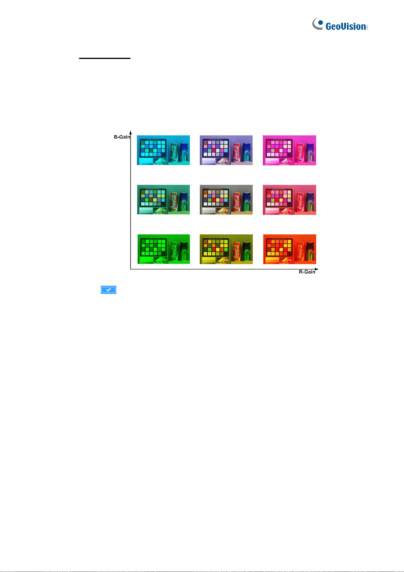
80
Manual Mode
In this mode, users can change the White Balance value manually via
specifying R gain and B gain; the range of R/B gain is from 0 to 127.
The following image displays the general color shifts of the scene when different
Rgain / Bgain combinations are applied.
Click to confirm the setting.

Main Tabs
81
2
2.4.3
Picture Adjustment
The Picture Adjustment setting can be found under this path: Image > Picture
Adjustment.
Brightness
The brightness level of the images is adjustable from -12 to +13.
Sharpness
The sharpness level of the images is adjustable from +0 to +15. The edge of the
objects is enhanced as the sharpness level increases.
Contrast
The contrast level of the images is adjustable from -6 to +19.
Saturation
The saturation level of the images is adjustable from -6 to +19.
Hue
The hue level of the images is adjustable from -12 to +13.

82
2.4.4
Color Style
The Color Style setting can be found under this path: Image > Color Style.
The camera provides three Color Style modes for delivering optimized image
quality in different light conditions.
Normal
The Normal Color Style mode is the default color setting.
Dark Detail Brighter
The Dark Detail Brighter Color Style mode brightens up dark parts of images.
Highlight Detail Brighter
The Highlight Detail Brighter Color Style mode makes images brighter and
balances image details under the light.

Main Tabs
83
2
2.4.5
IR Function
The IR Function setting can be found under this path: Image > IR Function.
Day/Night Function
This item is for users to define the action of the IR cut filter and IR LED lights.
Refer to the descriptions of each option below to select a suitable mode.
Auto Mode
With this mode, the camera will decide the occasion to remove the IR
cut filter.
Night Mode
Use this mode when the environment light level is low. The IR cut filter
will be removed to allow the camera to deliver clear images in black and
white.
Day Mode
Select this mode to turn on the IR cut filter. The IR cut filter can filter out
the IR light and allows the camera to deliver high quality images in color.
Light Sensor Mode
IR LED lights will be turned on / off depending on the light sensor.
Light On Mode
In this mode, IR LED lights will always be on.
Light Off Mode
In this mode, IR LED lights will always be off.
Smart Mode
With Smart mode, the camera will decide the occasion to remove the IR
cut filter. The Smart mode mechanism can judge whether the main light
source is from IR illumination. If the main light source is from IR
illumination, the IR cut filter will be kept opened (i.e. monochrome/night
mode).
84
Day/Night Threshold
This item is for users to set when the camera should switch from day mode to night
mode or vice versa. The camera will sense the surrounding brightness, and the
threshold value stands for the level of the light. Once the camera detects the
light level reaches the set threshold, the camera will automatically switch to
Day/Night Mode. The range of the level is from 0 to 10, (darker = 0; brighter = 10).
Night Mode to Day Mode
The lower the value, the earlier the camera switches to Day mode. The default
value is 7.
Day Mode to Night Mode
The higher the value, the earlier the camera switches to Night mode. The
default value is 3.
NOTE: This function can only be applied under “Auto Mode”.
IR Light Compensation
With the IR Light Compensation function, the camera can prevent the center
object close to the camera from being too bright when IR LED lights are turned on.

Main Tabs
85
2
2.4.6
Noise Reduction
The Noise Reduction setting can be found under this path: Image > Noise
Reduction.
The camera provides multiple <Noise Reduction> options for delivering
optimized image quality especially in extra low-light conditions.
3DNR
With the 3D Noise Reduction function, the processor analyzes the differences
between successive frames to adjust pixels and improve image quality. 3DNR
generates better de-noising effects than 2DNR, but might create motion blur on
moving objects in the field of view.
Different levels of 3DNR are provided, including Low, Mid and High. Higher level
of 3DNR generates relatively enhanced noise reduction.
2DNR
With the 2D Noise Reduction function, the processor analyzes individual frames
of video to eliminate environmental noise signal so that the highest quality
image can be produced even in low light conditions
Select <On> to turn on 2DNR function; otherwise, select <Off> to turn off 2DNR
function.
ColorNR
In a dark or insufficient light environment and the camera is under color mode,
ColorNR (Color Noise Reduction) can eliminate color noise.
Three levels of ColorNR, including Low, Mid and High, are provided. The higher
level of ColorNR generates relatively enhanced noise reduction.

86
2.4.6
WDR Function
The WDR setting can be found under this path: Image > WDR Function.
The Wide Dynamic Range (WDR) function is for solving high contrast or
changing light issues so that enhances better video display.
WDR function is designed to solve contrast or changing light issues and to
enhance the video display quality. Different level options for WDR function
include Low, Mid and Hi. The higher the level, the wider the dynamic range is.
Thus, the camera can catch a greater scale of brightness.
2.4.7
Backlight
The Backlight setting can be found under this path: Image > Backlight.
Select On to enable Backlight. This function is used to adjust the color intensity
of scenes with strong light at the background.
2.4.8
Profile
The Profile setting can be found under this path: Image > Profile.
Camera Profile allows users to setup the desired image parameters for specific
environments with different time schedules. Users can setup at most 10 sets of
camera parameter configuration under the Camera tab. To enable this function,
users must setup the schedules in advance. Refer to section Schedule for
further details. Then, follow the steps below to setup a camera profile.
Camera Profile Setup
Step 1. In the “Camera” tab, setup the camera parameters, such as Exposure,
White Balance, etc., excluding TV System.
Step 2. Click Profile and its setting menu will be displayed. Select a number
from the Num drop-down list.
Step 3. Input a name for the profile in the Name field.
Step 4. Click the <Save> button below the Name field. The camera
configuration is saved and applied to the profile.

Main Tabs
87
2
Step 5. Select a saved camera profile from the Num drop-down list.
Step 6. Tick the By schedule box. Check the desired schedule(s) from the
Schedule drop-down list. Multiple schedules can be applied to one
profile.
Step 7. Click the <Save> button below <By schedule>.
Step 8. Follow the steps above to set the rest of the profiles.
Now, the camera will automatically switch profiles according to the schedule.
Alternatively, manually select a number from the Num drop-down list. Click the
<Load> button , and the camera will apply the setting of the profile.
NOTE: If users wish to set the camera parameters to factory default setting,
select <Normal> from the Num drop-down list. The camera will
start loading the default values.
2.4.9
Fisheye Setting
The Fisheye setting can be found under this path: Image > Fisheye Setting.
At this setting page, users can choose a dewarping type for correcting the
fisheye source images, and select the camera’s installation method to view the
dewarped images with the correct viewing modes.
Fisheye Dewarping Type
On-Edge Dewarping
On-Edge Dewarping is a dewarping method that corrects fisheye source
images only by the camera. Dewarping images by the camera can
reduce network usage and image processing load of the backend device.
It also allows the camera to record or take snapshots of the dewarped
images.
Software Dewarping
Software Dewarping is a dewarping method that corrects the fisheye
source images by a backend device or a backend software with
dewarping function. Dewarping by this method can correct high
resolution images and deliver clear dewarped images.
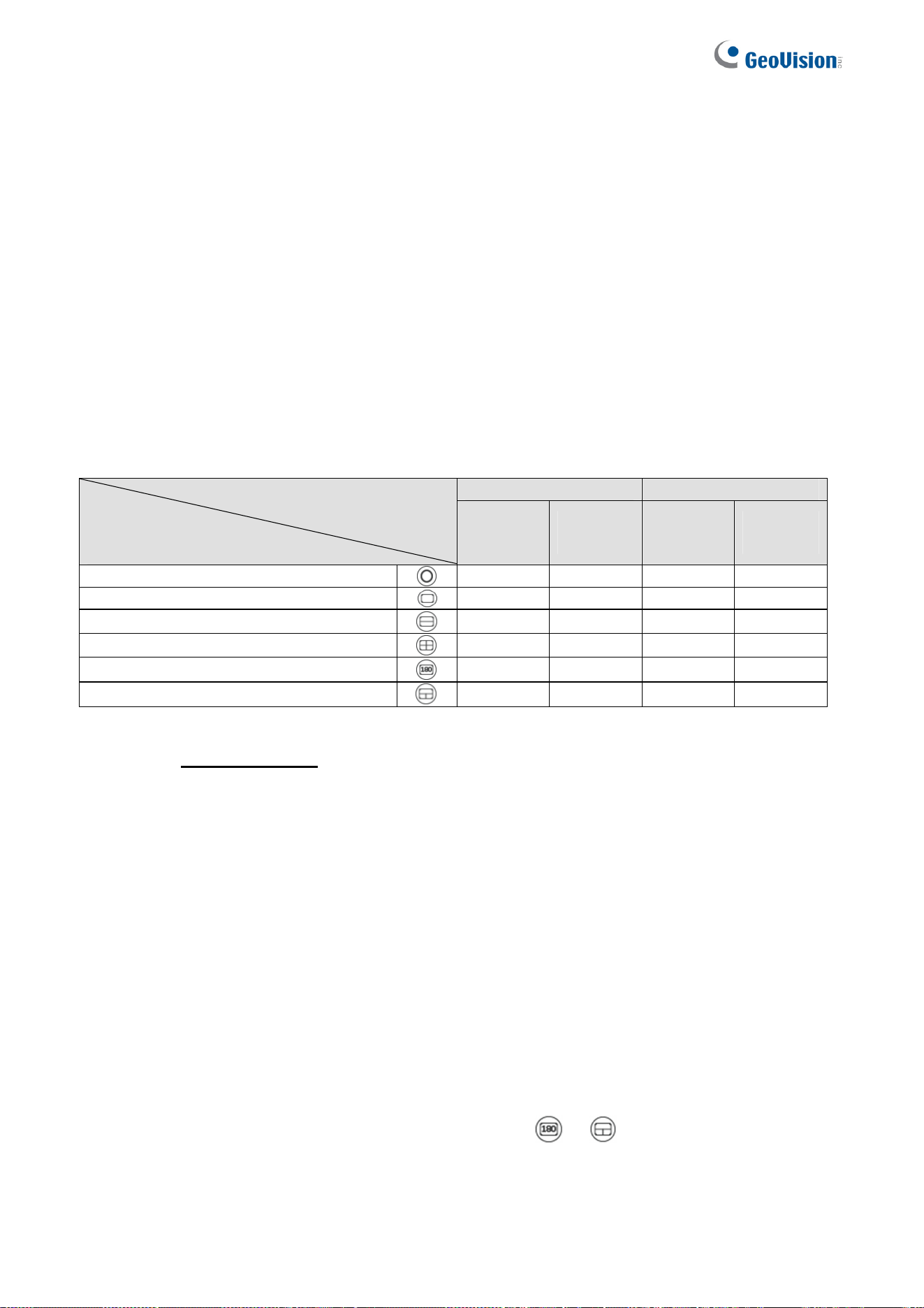
88
NOTE:
1. If the camera is switched to Software Dewarping, it is recommended to avoid
using the resolution of 1920 x 1080 which will result in distorted images.
2. The On-Edge Dewarping supports up to 8 MP while the Software Dewarping
supports up to 12 MP.
3. The On-Edge Dewarping allows stream 1 and 2 to use different selections of
Fisheye Image Adjustment (Fisheye Image Adjustment, 2.1 Home Page). To
display the same image orientation on both streams, select the same
Fisheye Image Adjustment.
The available Fisheye Image Adjustment buttons are different according to the dewarping
type and installation method selected on the <Fisheye Setting> page. The following table
shows the available buttons in different dewarping types and installation methods. The
supported buttons are represented by “v”.
On-Edge Software Dewarping Type/
Installation Method
Button
Ceiling
Mount
Wall
Mount
Ceiling
Mount
Wall
Mount
Fisheye View
v v v v
Single View
v v v v
Dual 180 Degree
v - v -
Quad View
v - v -
180 Degree
- v - v
360 Degree
- v - v
Fisheye Setting
Step 1. In the left menu, select Fisheye Setting.
Step 2. Under Fisheye Dewarping Type, <Software Dewarping> is selected
by default. Select <On-Edge Dewarping> if necessary.
Step 3. Under Installation, <Ceiling Mount> is selected by default. Select
<Wall Mount> if the camera is mounted to the wall. Click Save.
Step 4. Only if <Software Dewarping> is selected under Fisheye Dewarping
Type and <Wall Mount> under Installation, click the number <1> or <10>
under Horizontal Calibration to rotate the image. Click Save.
Step 5. In the “Home” tab, click the button or , the live view is displayed
as set up in the Fisheye Setting.

Main Tabs
89
2
2.4.10
TV System
Select the video format that matches the present TV system.
The following table shows the available video formats of the GV-
QFER12700.
Video Format
NTSC 30 fps
PAL 25 fps
2.5 Logout
Click the tab <Logout> on the top of the page, and the login window will pop up.
This enables login with another username.

90
Appendix A: Install UPnP Components
Please follow the instructions below to install UPnP components on Windows Vista /
Windows XP / Windows 7.
Step 1: In Windows, go to <Start>, click <Control Panel>, and then double click <Add or
Remove Programs>.
Step 2: Click <Add/Remove Windows Components> in the <Add or Remove Programs>
page.
Step 3: Select <Networking Services> from the Components list in Components Wizard
window of the Windows, and then click <Details>.
Step 4: Select <UPnP User Interface> in the Networking Services’ subcomponents list and
then click <OK>.
Step 5: Click <Next> in the Windows Components Wizard window.
Step 6: Click <Finish> to complete installation.
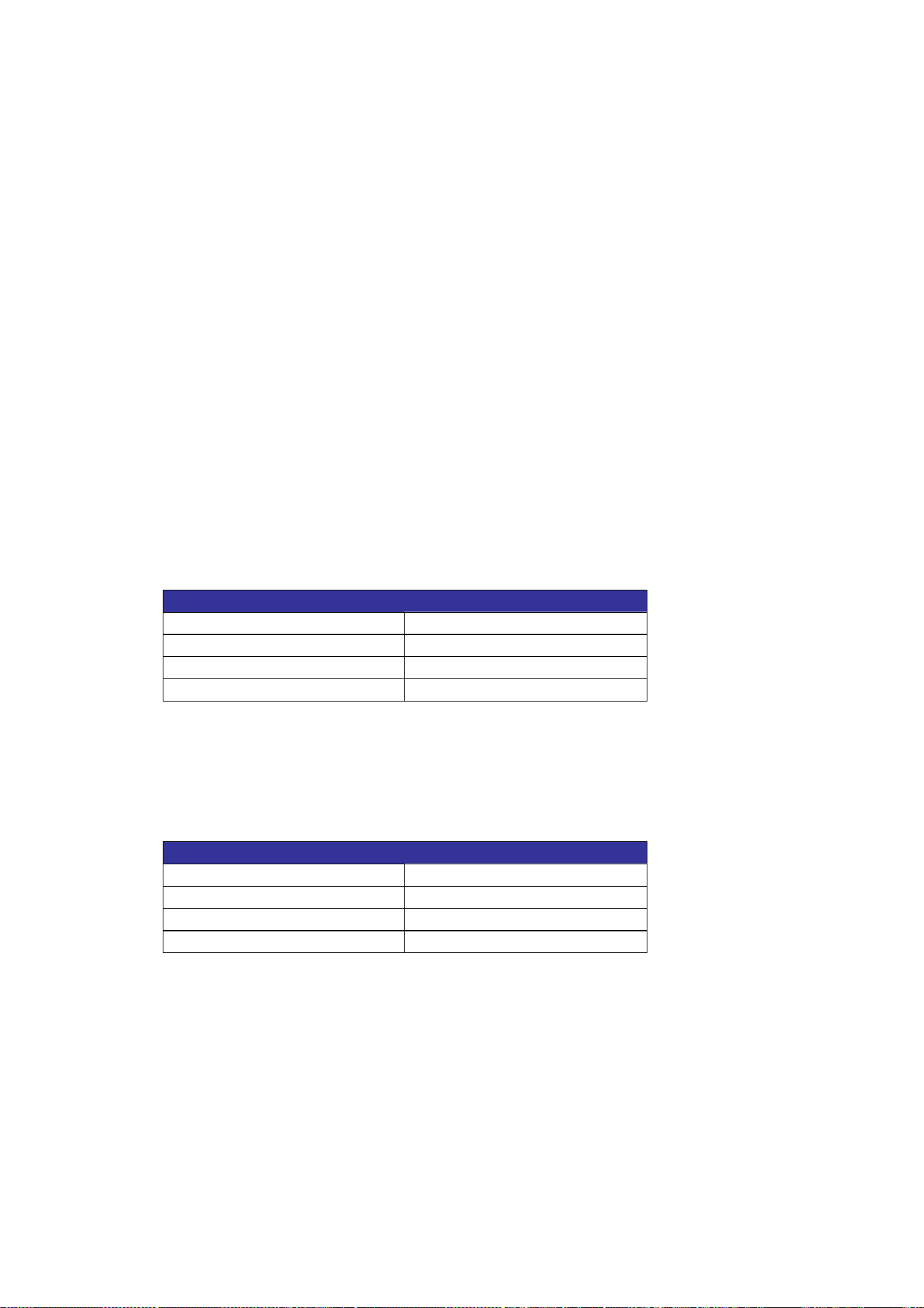
Appendix
91
Appendix B: IP Addresses from Decimal to Binary
Follow the example below to convert the IP addresses to binary numbers. Use the
calculator on the computer for conversion. The calculator can be found under this path:
Start> All Programs> Accessories> Calculator. For Windows XP and Windows Vista,
click <View> on the calculator and click <Scientific>. For Windows 7 or above, click <View>
on the calculator and click <Programmer>. Then follow the steps in the following example
to convert the IP addresses.
The example below shows how to convert 192.168.2.81 to binary numbers.
Step 1: On the left of the calculator, select <Dec>. Then enter the first decimal number of
the IP address, “192”. Select <Bin> and the number will be converted to binary
number. Repeat the same procedure with the rest of decimal numbers. Remember
to select <Dec> before entering the next decimal number. Otherwise a decimal
number cannot be entered. The table below shows the binary number of each
decimal number.
Decimal Numbers Binary Numbers
192 11000000
168 10101000
2 10
81 1010001
Step 2: Each binary number should have eight digits. If a binary number does not have
eight digits, please add 0 in front of it until it does. The binary number of each
decimal number should be as follow.
Decimal Numbers Binary Numbers
192 11000000
168 10101000
2 00000010
81 01010001
Step 3: Therefore, the binary numbers of IP address 192.168.2.81 is
11000000.10101000.00000010.01010001.
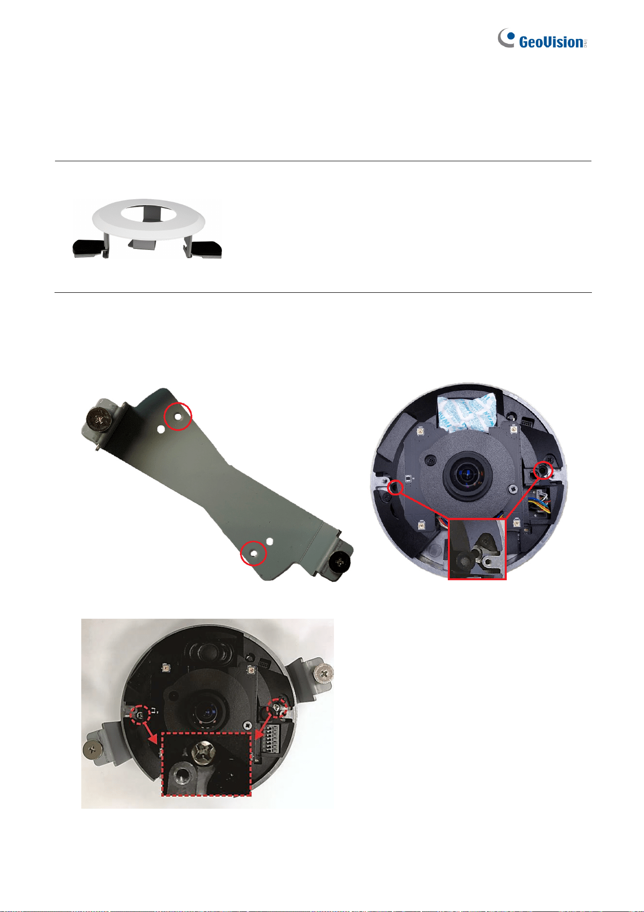
92
Appendix C: In-Ceiling Mount Installation
GV-QFER12700 can be installed to the ceiling with GV-Mount919. Follow the steps below
to install the in-ceiling mount.
Packing List
In-Ceiling Mount Bracket
In-Ceiling Plate
Template Paster
M3x18 Mechanical Screw x 2
In-Ceiling Cover
Torx Wrench
1. Loosen the two screws on the dome cover with the supplied torx wrench, and remove
the dome cover by pulling it apart from the camera.
2. Fit the camera into the In-Ceiling Plate, and align the two indicated holes on the camera
to the two indicated holes on the In-Ceiling Plate.
3. Fasten the two supplied M3x18 mechanical screws at the two aligned holes to fix the
camera to the In-Ceiling Plate.
4. Place the template paster on the ceiling and cut out the circle part.
5. Place the In-Ceiling Mount Bracket into the ceiling with the flat side facing down.
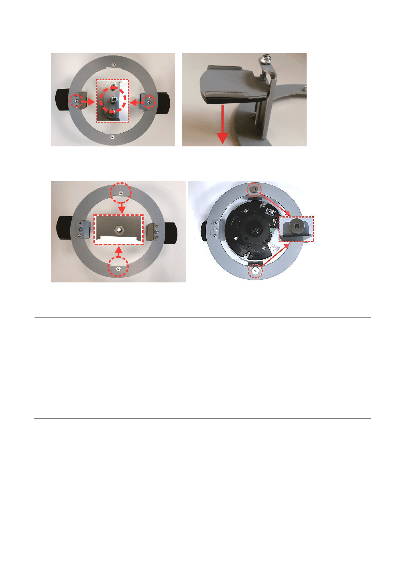
Appendix
93
6. Clamp the In-Ceiling Mount Bracket on the ceiling by tightening the two indicated screws.
7. Place the camera attached to the In-Ceiling Plate into the In-Ceiling Mount Bracket.
8. Align the two screws of the In-Ceiling Plate to the indicated holes of the In-Ceiling Plate,
and tighten the screws.
9. Close and secure the dome cover. Connect the camera wires to the necessary wires.
10. Put on the In-Ceiling Cover to finish installation.
Note: GV-QFER12700 can be installed to the wall with GV-Mount206-1 / 903-2 / 904-2 / 912-1.
Refer to the following sections of GV-Mount Accessories Installation Guide.
GV-Mount 206-1 (5.4.2 GV-FER5701 / FER12203 / FER12700 / EFER3700 / EFER3700-W /
QFER12700, GV-Mount Accessories Installation Guide)
GV-Mount903-2 (5.1.2 GV-EFER3700 / GV-EFER3700-W / GV-QFER12700, GV-Mount
Accessories Installation Guide)
GV-Mount904-2 (5.6.2 GV-Mount904-1, GV-Mount Accessories Installation Guide)
GV-Mount912-1 (5.12 Power Box Mount, GV-Mount Accessories Installation Guide)
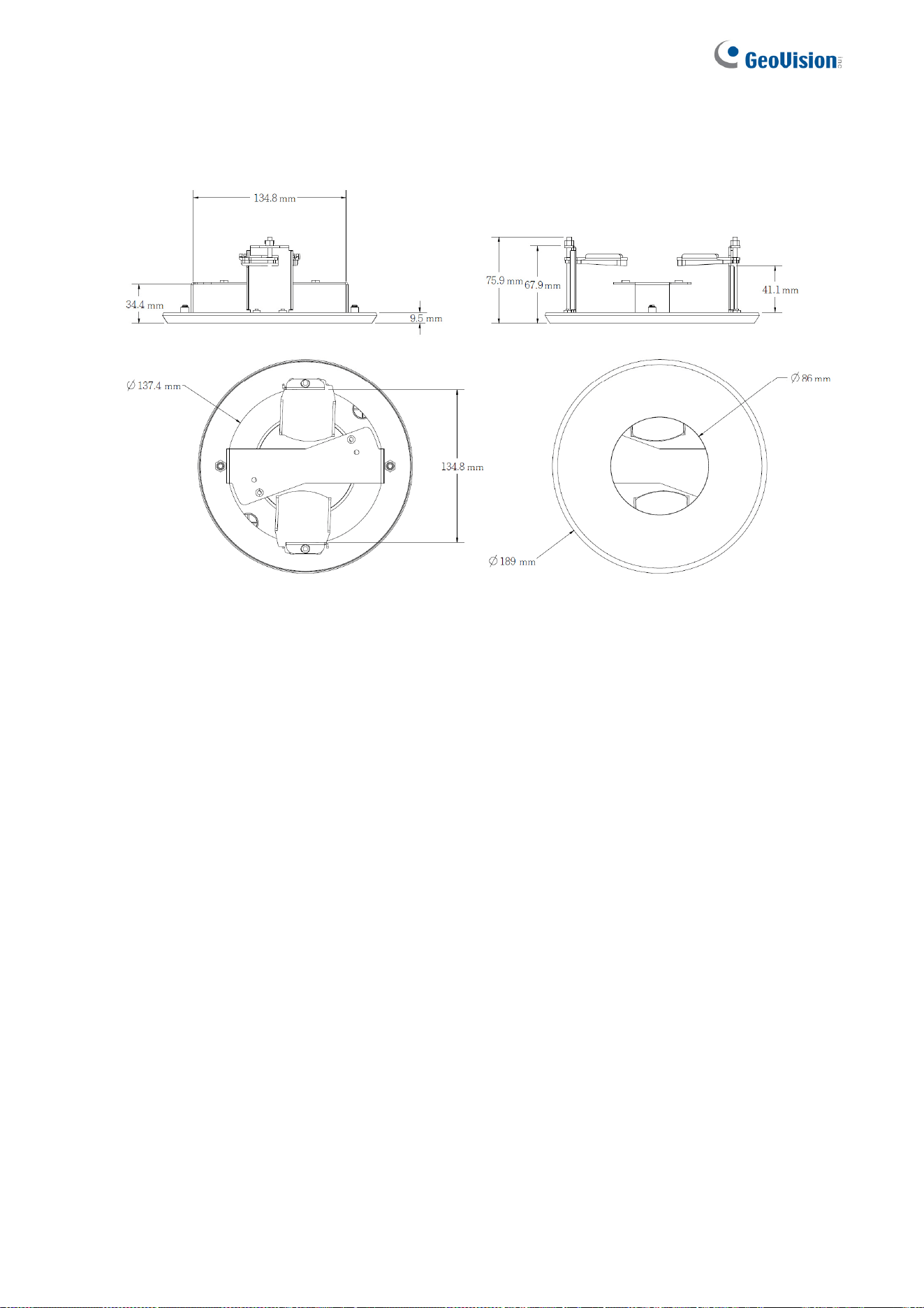
94
Appendix D: Dimensions
GV-Mount919