
© 2023 GeoVision, Inc. All rights reserved.
Under the copyright laws, this manual may not be copied, in whole or in part,
without the written consent of GeoVision.
Every effort has been made to ensure that the information in this manual is
accurate. GeoVision, Inc. makes no expressed or implied warranty of any kind
and assumes no responsibility for errors or omissions. No liability is assumed
for incidental or consequential damages arising from the use of the information
or products contained herein. Features and specifications are subject to
change without notice.
GeoVision, Inc.
9F, No. 246, Sec. 1, Neihu Rd.,
Neihu District, Taipei, Taiwan
Tel: +886-2-8797-8377
Fax: +886-2-8797-8335
http://www.geovision.com.tw
Trademarks used in this manual: GeoVision, the GeoVision logo and GV
series products are trademarks of GeoVision, Inc. Windows is the registered
trademark of Microsoft Corporation.
September 2023
Scan the following QR codes for product warranty and technical support
policy:
[Warranty] [Technical Support Policy]

Contents
Chapter 1. Introduction ................................................................................................................ 1
Safety Instruction ..................................................................................................................... 1
Chapter 2. Product Description .................................................................................................... 2
2.1 Product Overview .............................................................................................................. 2
2.2 Key Features ..................................................................................................................... 2
2.3 System Requirements ........................................................................................................ 4
Chapter 3. Configuration Flow ..................................................................................................... 5
Chapter 4. Network Connection ................................................................................................... 7
4.1 Setting the Camera over the LAN
...................................................................................... 7
4.1.1 Connect via a Switch or a Router
................................................................................ 7
4.2 Dynamic IP Connection...................................................................................................... 8
Chapter 5. Accessing the Network Camera
................................................................................. 9
5.1 Assigning An IP Address .................................................................................................... 9
5.1.1 Assigning An IP Address Using GV-IP Device Utility ................................................... 9
5.1.2 Assign An IP Address via Browser
............................................................................ 10
5.2 Accessing from the Web Browser
................................................................................... 13
Chapter 6. Live View ................................................................................................................. 14
6.1 Fisheye Mode................................................................................................................... 14
6.1.1 Operations on Live View Page .................................................................................. 15
6.1.2 Set / Call a Preset / Patrol
......................................................................................... 22
Chapter 7. Playback .................................................................................................................. 27
Chapter 8. Settings .................................................................................................................... 31
8.1 Media ............................................................................................................................... 31
8.1.1 Video ......................................................................................................................... 31
8.1.2 Image ........................................................................................................................ 35
8.1.3 Audio ......................................................................................................................... 49
8.2 Network ........................................................................................................................... 52
8.2.1 Basic ......................................................................................................................... 52
8.2.2 Advanced .................................................................................................................. 63
8.3 Storage ............................................................................................................................ 77
8.3.1 Storage Management ................................................................................................ 78
8.3.2 Record Settings ......................................................................................................... 78

8.3.3 Snapshot Settings ..................................................................................................... 81
8.3.4 Explorer ..................................................................................................................... 83
8.4 Event ............................................................................................................................... 84
8.4.1 Basic Event ............................................................................................................... 84
8.4.2 VCA Event ................................................................................................................. 92
8.4.3 Object Counting ...................................................................................................... 116
8.4.4 Heat Map ................................................................................................................. 135
8.5 Fisheye .......................................................................................................................... 143
8.6 System ........................................................................................................................... 145
8.6.1 System Setting ........................................................................................................ 145
8.6.2 Security ................................................................................................................... 146
8.6.3 Logs ........................................................................................................................ 153
8.6.4 Maintenance ............................................................................................................ 155
Appendix ................................................................................................................................. 158
A. Optional Installation ........................................................................................................ 158
1. GV-Mount211-7 .............................................................................................................. 158
2. GV-Mount430 ................................................................................................................. 161
3. GV-Mount508 ................................................................................................................. 163
B. Note for Fisheye Camera with IR LED ............................................................................ 166

1
Chapter 1. Introduction
Safety Instruction
These instructions are intended to ensure that user can use the product correctly to
avoid danger or property loss. The precaution measures are divided into “Warnings”
and “Cautions”
Warnings: Serious injury or death may be caused if any of these warnings is neglected.
This installation must be conducted by a qualified service person and should
strictly comply with the electrical safety regulations of the local region
To avoid risk of fire and electric shock, do keep the product away from rain
and moisture before installed.
Do not touch components such as heat sinks, power regulators, and
processors, which may be hot
Source with DC/ AC 12V or PoE
Please make sure the plug is firmly inserted into the power socket
When the product is installed on a wall or ceiling, the device should be
firmly fixed
If the product does not work properly, please contact your dealer. Never attempt
to disassemble the camera by yourself
Cautions: Injury or equipment damage may be caused if any of these cautions are
neglected.
Make sure that the power supply voltage is correct before using the camera
Do not store or install the device in extremely hot or cold temperatures, dusty
or damp locations, and do not expose it to high electromagnetic radiation
Only use components and parts recommended by manufacturer
Do not drop the camera or subject it to physical shock
To prevent heat accumulation, do not block air circulation around the
camera
Laser beams may damage image sensors. The surface of image sensors
should not be exposed to where a laser beam equipment is used
Use a blower to remove dust from the lens cover
Use a soft, dry cloth to clean the surface of the camera. Stubborn stains can
be removed using a soft cloth dampened with a small quantity of detergent
solution, then wipe dry
Do not use volatile solvents such as alcohol, benzene or thinners as
they may damage the surface finishes
Save the package to ensure availability of shipping containers for future
transportation

2
Chapter 2. Product Description
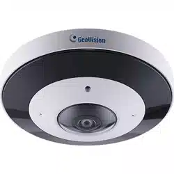
2.1 Product Overview
GeoVision provides a consistent range of cost-effective and reliable network cameras to
fully meet your requirements. Based on embedded Linux operating system, GeoVision’s
fisheye IP camera could be easily accessed and managed either locally or remotely with
great reliability. With built-in high-performance DSP video processing modules, the
cameras pride on low power consumption and high stability. They support state-of-the-art
H.265/ H.264 video compression algorithm and industry-leading HD dual-stream
technology to achieve the highest level of video image quality under the limited network
resources. It is fully functional, supporting for flexible and comprehensive alarm linkage
mechanism, day and night auto switch and privacy masking, etc.
In practical applications, GeoVision’s fisheye IP camera could either work
independently in the LAN, or be networked to form a powerful safety monitoring
system. It is widely used in fields such as finance, education, industrial production,
civil defense, health care for security’s sake.
2.2 Key Features
System
Built-in WEB server, support IE/ Firefox/ Chrome/ Safari browser
Based on Linux OS with high reliability
Support Plugin- Free mode
Support activation and set- up of the security questions for cameras
Support ONVIF Profile G & Q & S & T
Three- privilege levels of users for flexible management
Micro SD/ SDHC/ SDXC card local storage support, expand the edge storage
Image
0.005Lux Ultra Low Light
Smart IR II technology
12 MP Video Viewing Experience
Support HLC
Support BLC
ICR filter with auto switch, true day/night
H.265/ H.264 video compression capability
70% ~ 80% bandwidth saved by 10-level adjustable H.265+
Support Primary Stream/ Secondary Stream/ Tertiary Stream
Real-time video electronic amplification

3
Audio
G.711 audio compression capability
Support Audio I/O
Network
UPnP protocol for the easy management of camera
Support DDNS
FTP upload, SMTP upload, SD card record and SIP phone
Advanced Function
Motion Detection, Privacy Masking, Network Fault Detection and ROI
Support AI Video Content Analysis
Support People Counting function
Support Heat Map function
Hardware
Support PoE for power supply
Support Alarm I/O
Built- in microphone
IK10-rated vandal-proof metal cover, and IP67- rated weather- proof housing
Fisheye
Up to 30fps @ 4000 × 3000
Support Hardware Dewarping and Software Dewarping
Support Auto Tracking function
11 display modes to meet various needs
Equipped with Audio I/ O and Alarm I/ O
IK10-rated vandal- proof metal cover, and IP67- rated weather- proof housing
Streamlined design, exquisite appearance
Easy to blend in with the installation environment

4
2.3 System Requirements
Operating System: Windows XP/Vista/7/8/10/Server 2000/Server 2008
CPU: 1.66GHz or higher
RAM: 1G or higher
Graphic memory: 128MB or more
Internet protocol: TCP/IP (IPv4/IPv6)
Web Browsers: Internet Explorer 8.0 and above version, Mozilla Firefox, Google
Chrome and Safari.
5
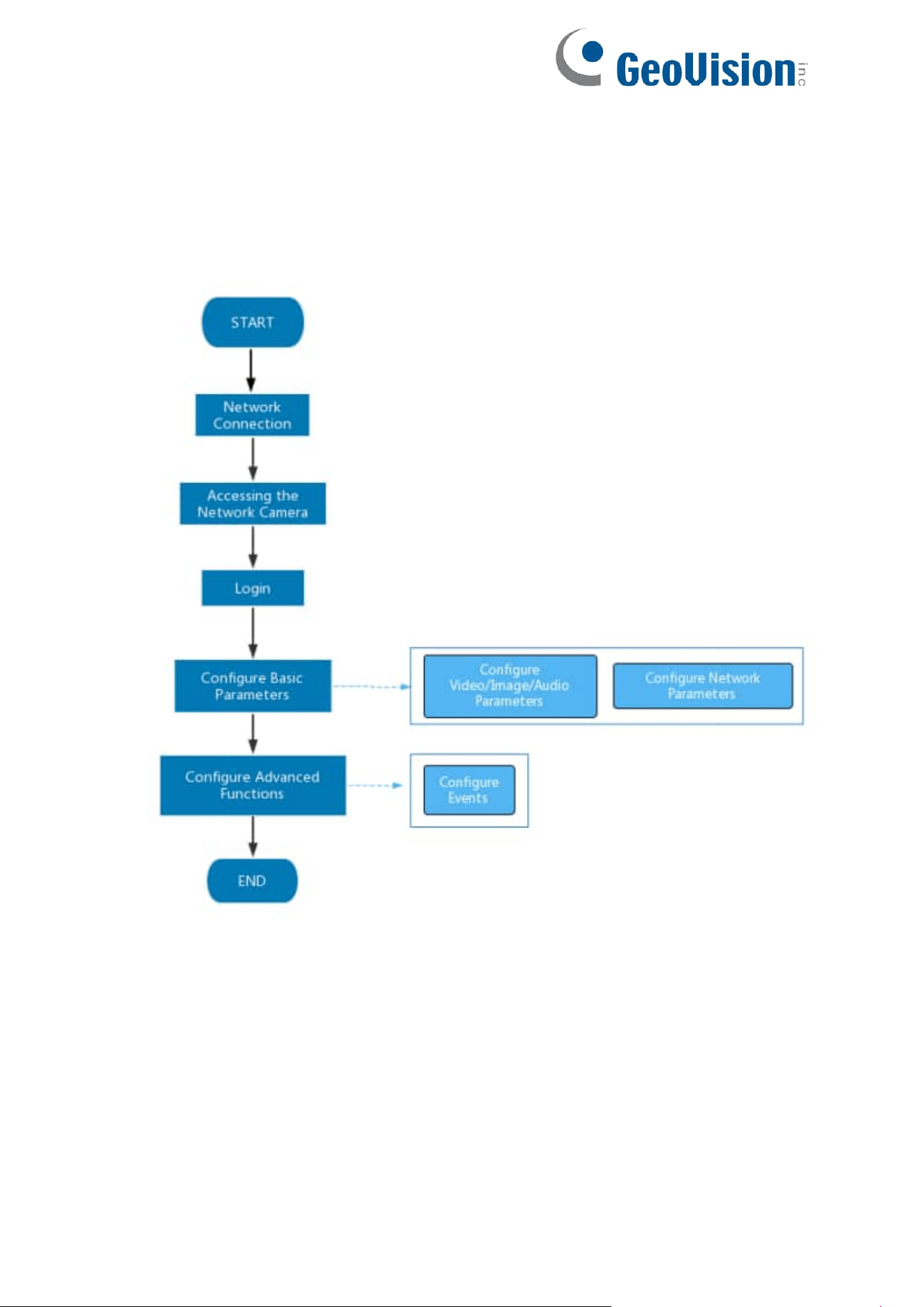
Chapter 3. Configuration Flow
The configuration flow of cameras is shown in the following figure.
Note: The configuration must be based on the actual situation of different models.
More configuration details are shown in the following table.

6
Table 1. Description of flow
Configuration
Description
Reference
Network Connection
Connect the network
camera. You can set the
camera over the LAN or
dynamic IP connection.
4.1 Setting the Camera
over the LAN
Accessing the Network
Camera
Accessing from IP
address, web browser
and back-end software
are available.
5.1 Assigning An IP
Address
Configure Basic
Parameters
After login the camera, you
can adjust the
video/image/audio/network
parameters as needed.
8.1 Media
8.2 Network
Configure Advanced
Functions
Configure the advanced
functions, such as VCA
and people counting.
8.4 Event
7
Chapter 4. Network Connection
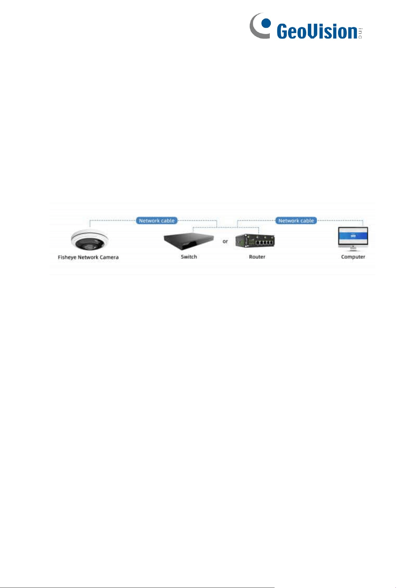
4.1 Setting the Camera over the LAN
Connecting the camera to a switch or a router is the most common connection method.
The camera must be assigned an IP address that is compatible with its LAN.
4.1.1 Connect via a Switch or a Router
Refer to the following figure to set network camera over the LAN via the switch or router.
8
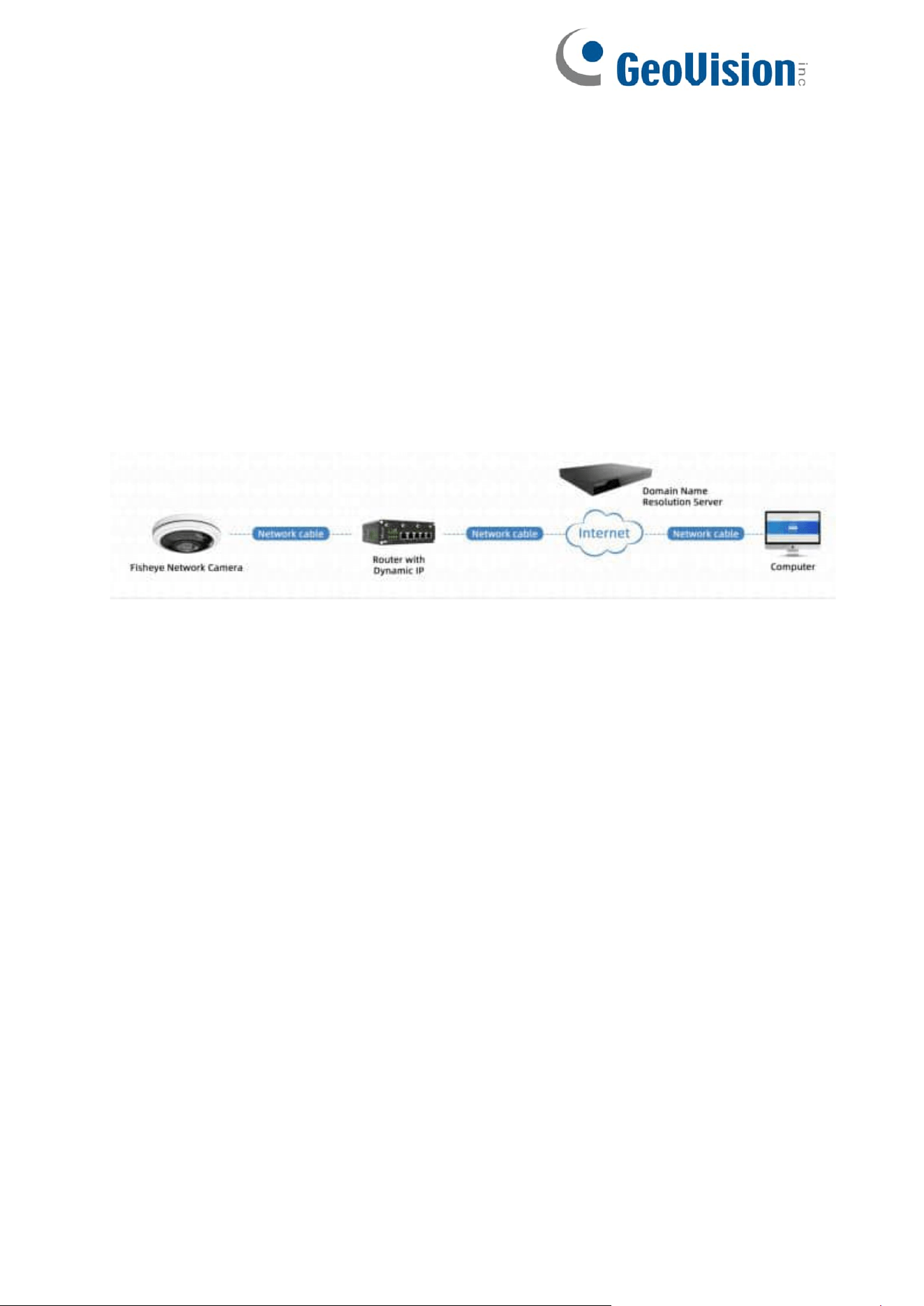
4.2 Dynamic IP Connection
Step 1: Connect the network camera to a router;
Step 2: On the camera, assign a LAN IP address, the Subnet mask and the Gateway;
Step 3: On the router, set port forwarding. E.g., 80, 8000 and 554 ports. The steps for
port forwarding vary depending on different routers. Please look up the router's user
manual for assistance with port forwarding;
Step 4: Apply a domain name from a domain name provider;
Step 5: Configure the DDNS settings in the setting interface of the router;
Step 6: Visit the camera via the domain name.

9
Chapter 5. Accessing the Network Camera
5.1 Assigning An IP Address
The Network Camera must be assigned an IP address to be accessible. The default
IP address of GeoVision fisheye IP cameras is 192.168.0.10.
You can either change the IP address of the camera via Smart Tools or browser. Please
connect the camera in the same LAN of your computer.
5.1.1 Assigning An IP Address Using GV-IP Device Utility
See Chapter 5 Advanced Settings here for assigning an IP address using GV-IP Device
Utility. Note that this function is only applicable on GV-IP Device Utility V8.9.9 or later.
10
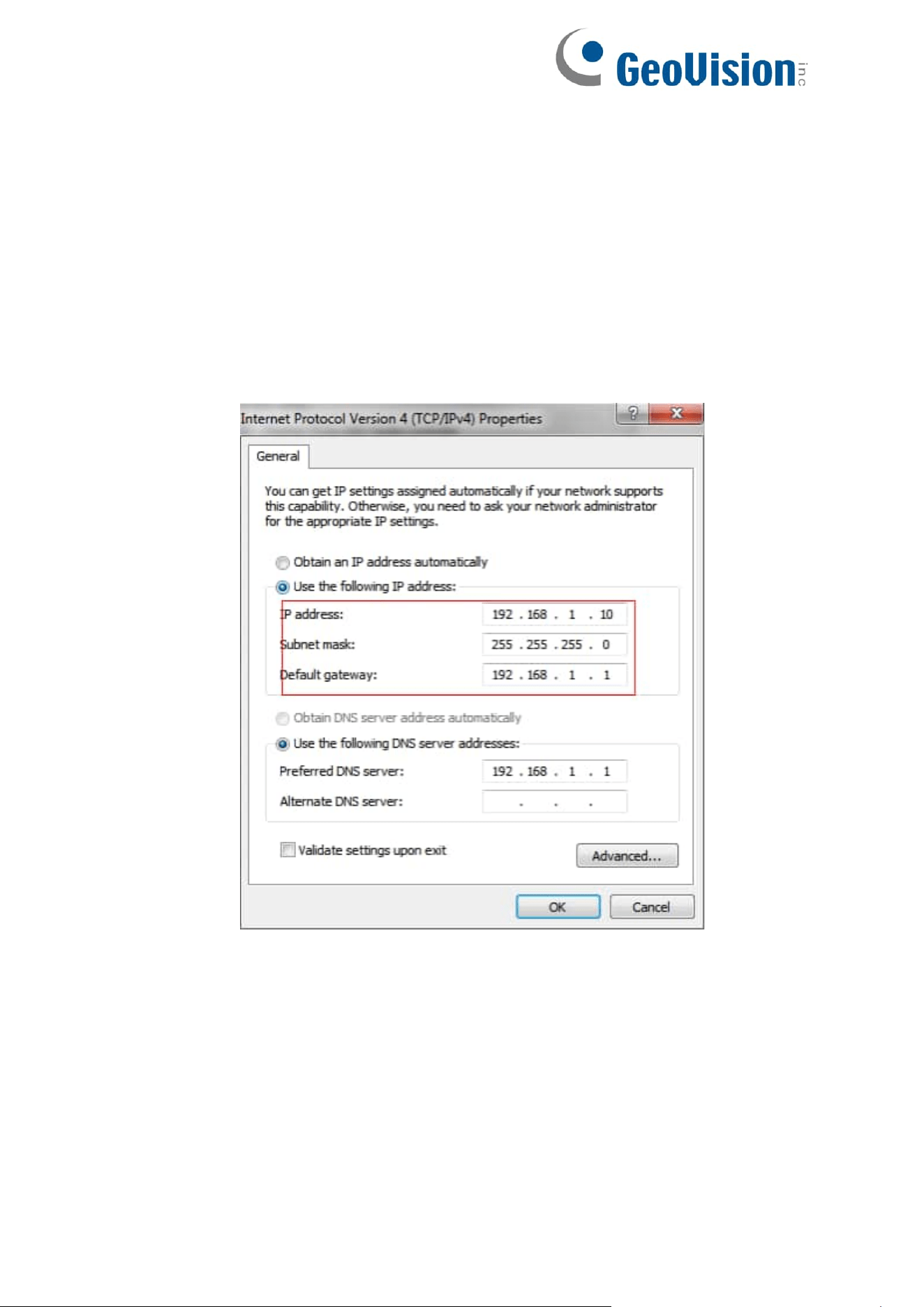
5.1.2 Assign An IP Address via Browser
If the network segment of the computer and that of the camera are different, please
follow the steps to change the IP address:
Step 1: Change the IP address of computer to 192.168.0.10 segment, here are two ways
as below:
a. Start→Control Panel→Network and Internet Connection→Network
Connection→Local Area Connection, and double click it;
11
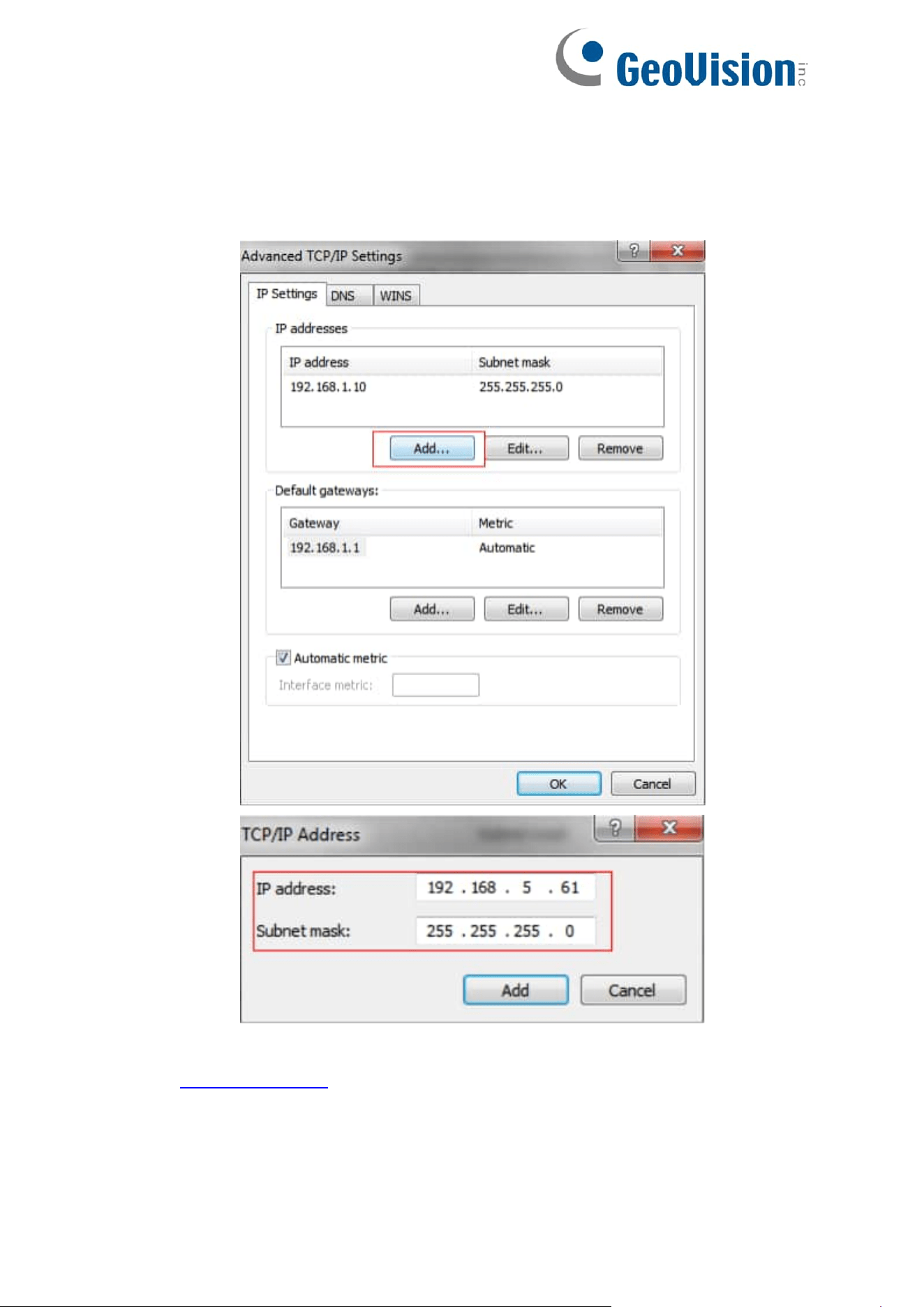
b. Click “Advanced”, and then click “IP settings”--> “IP address”--> “Add”. In the pop-
up window, enter an IP address that in the same segment with the camera (e.g.,
192.168.5.61, but please note that this IP address shall not conflict with the IP
address on the existing network);
Step 2: Start the browser. In the address bar, enter the default IP address of the
camera: http://192.168.0.10;
12
Step 3: You need to set the password first when using it for the first time. And you can
also set three security questions for your device after activation. Then you can log in to
the camera with the user name (admin) and a custom password.
Note:
Password must be 8 to 32 characters long, contain at least one number and
one letter.
You can click the “forget password” in login page to reset the password by
answering three security questions when you forget the password, if you
set the security questions in advance.
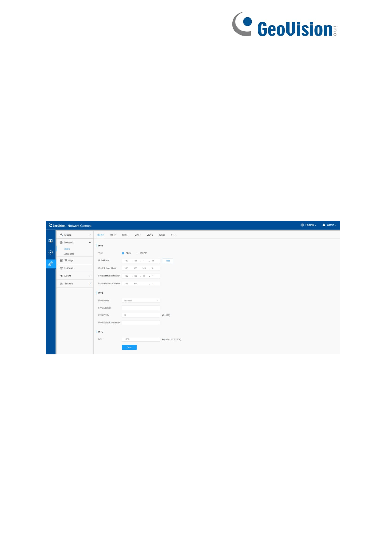
Step 4: After login, please select “Settings” → “Network” → “Basic” → “TCP/IP”. The
Network Settings page appears (shown as the figure below);
Step 5: Change the IP address or other network values. Then click “Save” button;
Step 6: The change of default IP address is completed.

13
5.2 Accessing from the Web Browser
The camera can be used with the most standard operating systems and browsers. And
the camera supports Plugin-Free Mode. In Plugin-Free Mode, you can preview the
video on the browser without plugin. Currently Plugin-Free Mode is supported in
Firefox & Google Chrome & Safari & Edge browser for Windows system, MAC system,
iOS system and Android system. Both H.265 & H.264 video codecs are supported in
Plugin-Free Mode for camera, and it will play the secondary stream by default.
Note: Currently you can only use the dewarping mode of fisheye cameras with plugin
via Internet Explorer.
14
Chapter 6. Live View
6.1 Fisheye Mode
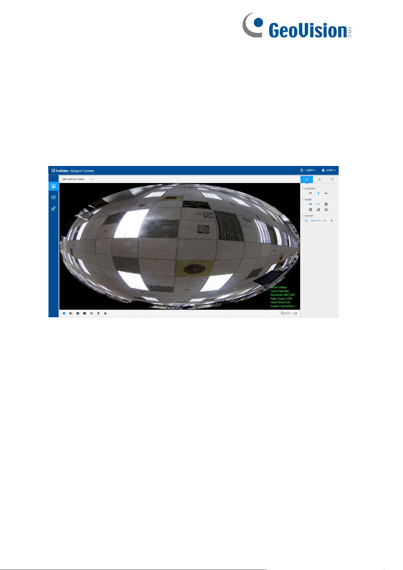
After logging in the network camera web GUI successfully, user is allowed to view
live video as follows.
Live view interface (Multi-Channel Mode):
15
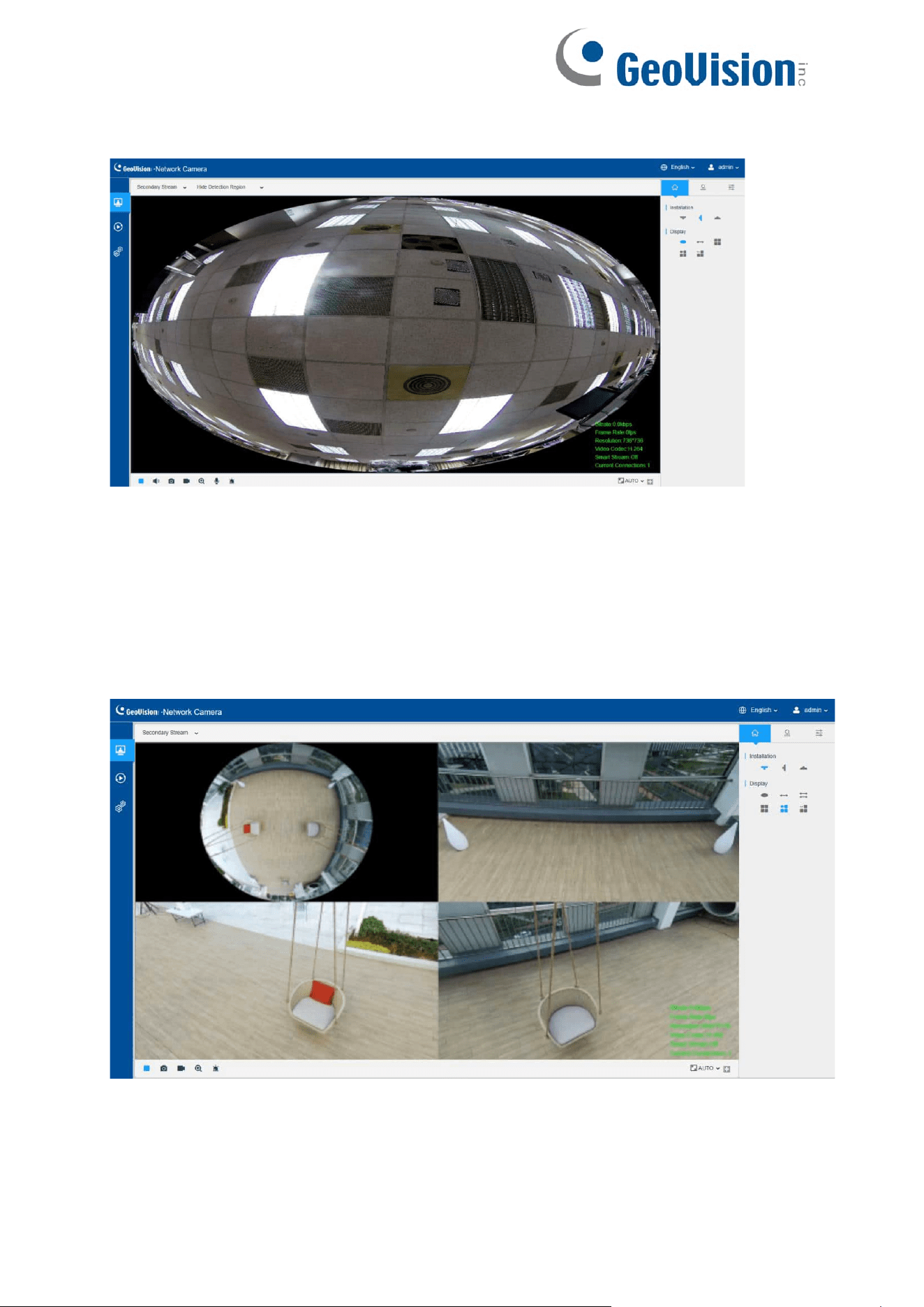
Live view interface (Bundle-Stream Mode):
6.1.1 Operations on Live View Page
[Display Control]
Display Control allows you to select install type, display mode, window screen and
channel of live view.

16
Table 2. Description of Display Control buttons
Item
Parameter
Description
Dewarping
Rule
Hardware Dewarping
Click to select on-board dewarping mode.
Software Dewarping
Click to select client-side dewarping mode.
Installation
Ceiling Mounting
Click to select ceiling mounting.
Wall Mounting
Click to select wall mounting.
Flat Mounting
Click to select flat mounting.
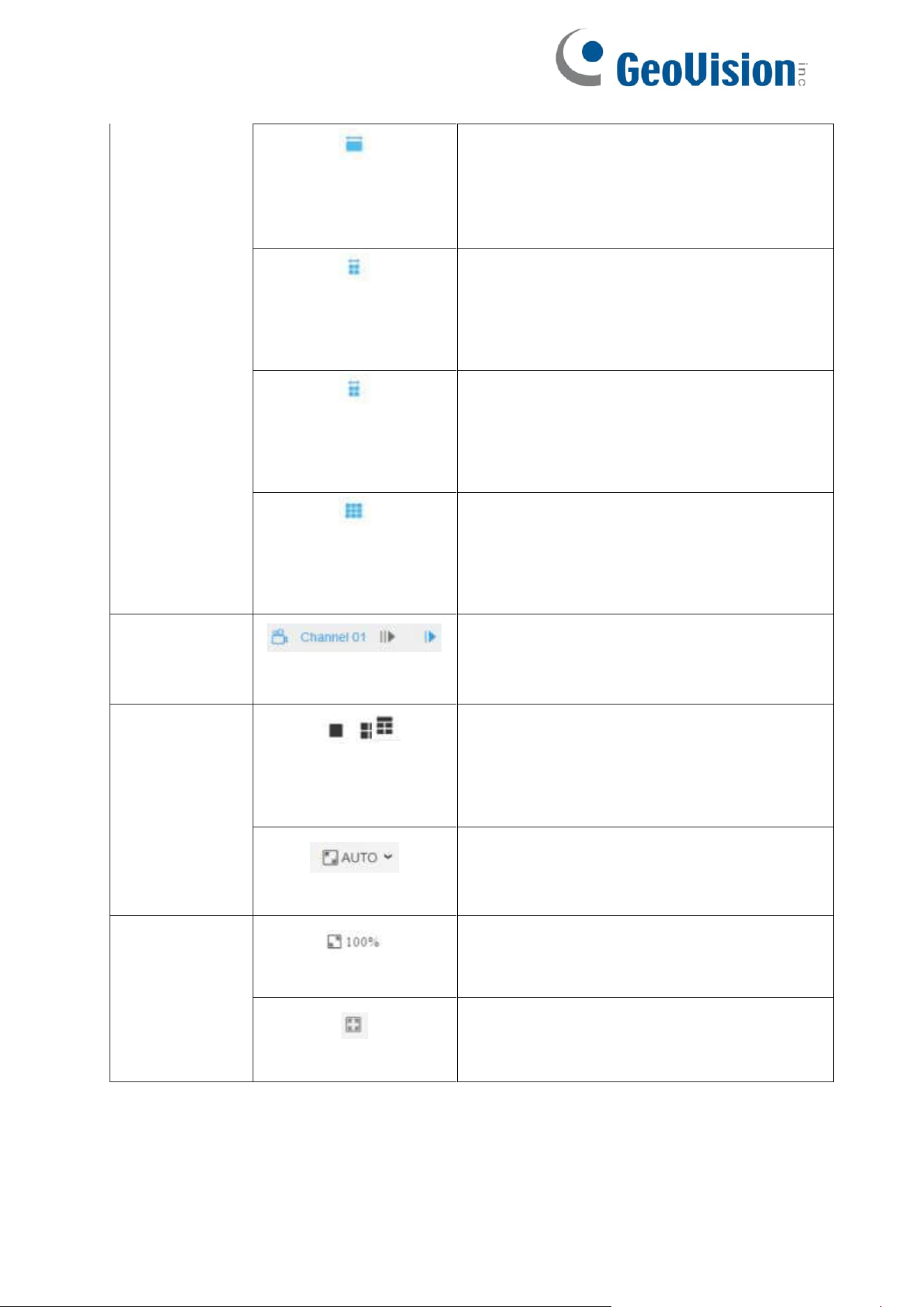
Display
1O
Select live view of original fisheye view.
1P
Select live view of 360° panoramic view.
2P
Select live view of two 180° panoramic views.
4R
Select live view of four regional views.
1O3R
Select live view of one original fisheye
view and three regional views.
1P3R
(Only for Hardware
Dewarping)
Select live view of one 360° panoramic
view and three regional views.
Display
1P3R
(Only for Multi-
Channel Mode of
Hardware Dewarping)
Select live view of one original fisheye
view, one 360° panoramic view and
three regional views.
17
1P1R
(Only for Software
Dewarping)
Select live view of one 360° panoramic
view and one regional view.
1P4R
(Only for Software
Dewarping)
Select live view of one 360° panoramic
view and four regional views.
1P6R
(Only for Software
Dewarping)
Select live view of one 360° panoramic view
and six regional views.
1O8R
(Only for Software
Dewarping)
Select live view of one original fisheye
view and eight regional views.
Channel
(Only for Multi-Channel
Mode)
Click to play this channel on any window of
live view.
Window
/ /
Window Layout
(Only for Multi-Channel
Mode)
Click to set window layout to “1*1”/ “2*2”/
“1+4”.
Window Size
Click to display images at a window size.
Display
Real Size
Click to display images at a real size.
Full Screen
Click to display images at full-screen.
Note:
•
Original fisheye view: The whole wide- angle view of the fisheye camera is
displayed.
18
• Panoramic view: The round fisheye image is transformed to
rectangular image by certain calibration methods.
• Regional view: The close- up view of defined area in the original
fisheye view or panoramic view.
•
Select the Installation, Display mode and the most appropriate Window
Layout in sequence.
[Live View Window]
Display live video on the window.
Note: It will capture images and record videos of first channel by default, you can also
capture images and record videos of specified channel manually.
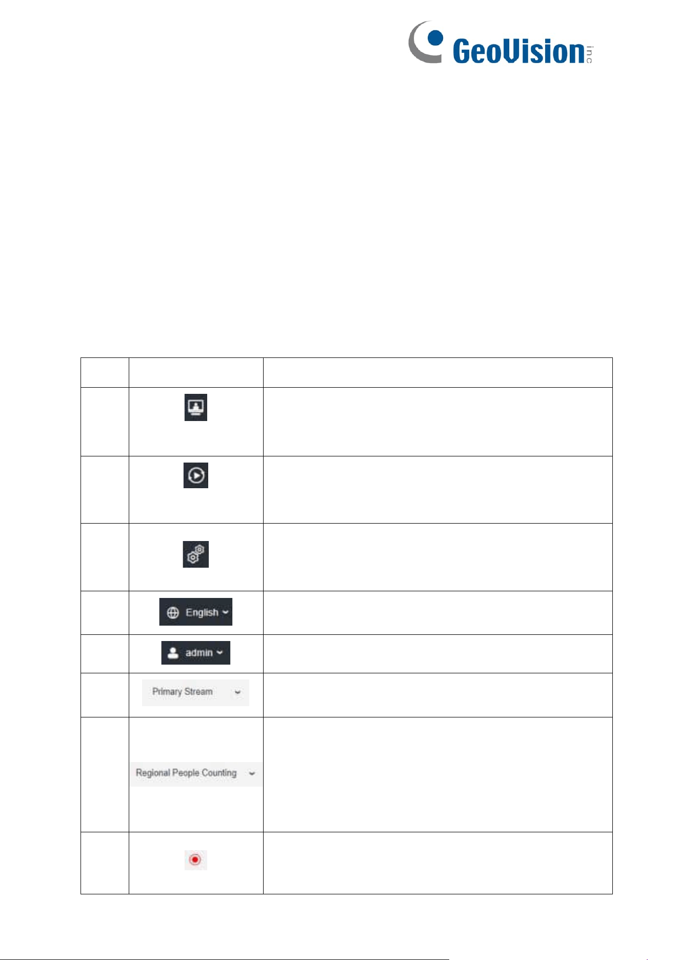
Table 3. Description of the buttons
No.
Parameter
Description
1
Live Video
Click to access the live view page.
2
Playback
Click to access the playback page.
3
Settings
Click to access the configuration page.
4
Click to select system language.
5
Display the user name and click to logout.
6
Choose the stream (Primary/Secondary/Tertiary) to
show on the current video window.
7
Choose the options (Hide Detection Region/Region
Entrance/Region Exiting/Advanced Motion/Line
Crossing/Loitering/People Counting/Object
Left/Object Remove/Regional People Counting) to
hide/display detection region on the current video
window.
8
Recording
When recording, the icon appears.
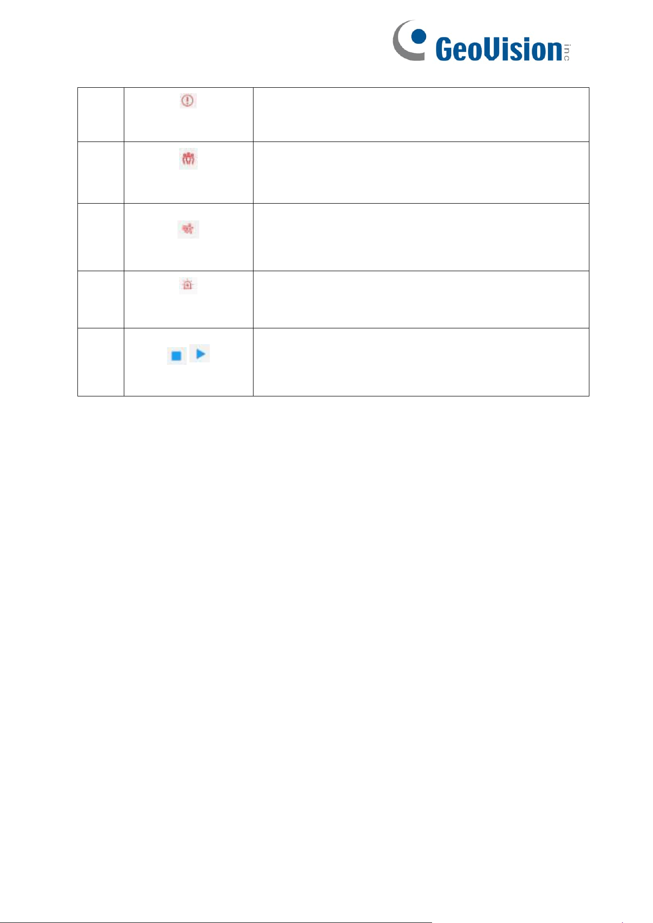
19
9
Alarm
When an alarm of VCA event was triggered, the icon
appears.
10
Alarm
When an alarm of people counting was triggered, the icon
appears.
11
Alarm
When an alarm of Motion Detection was triggered, the
icon appears.
12
Alarm
Except for the three kinds of alarms above, when
other alarms were triggered, the icon appears.
13
/
Stop/Play
Stop/Play live view.
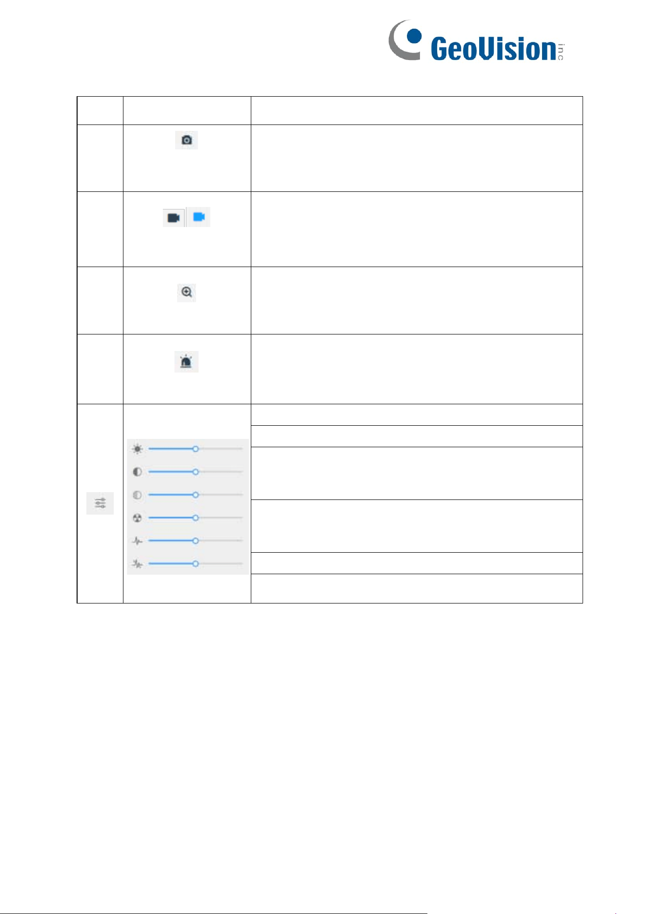
20
No.
Parameter
Description
14
Snapshot
Click to capture the current image and save to the
configured path. The default path is: C:VMS\+-1\
IMAGE-MANUAL.
15
/
Start/Stop
Recording
Click to Start Recording video and save to the
configured path. The default path is C:VMS\+-
1\MS_Record. Click again to Stop Recording.
16
Digital Zoom
When enabled, you can zoom in a specific area of
video image with your mouse wheel.
17
Manual Output
Manually trigger Camera Alarm Output.
Brightness: Adjust the Brightness of the scene.
Contrast: Adjust the color and light contrast.
Saturation: Adjust the Saturation of the image.
Higher Saturation makes colors appear “purer” while
lower one appears more “wash-out”.
Sharpness: Adjust the Sharpness of image. Higher
Sharpness sharps the pixel boundary and makes the
image looks “clearer”.
2D DNR/3D DNR: Adjust the noise reduction level.
Default: Restore brightness, contrast and saturation to
default settings.
21
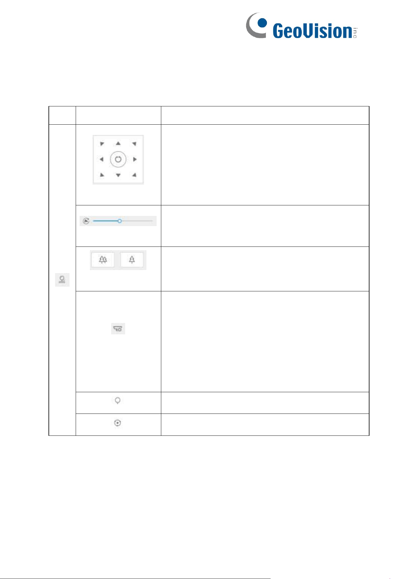
[PTZ Control]
PTZ Control allows you to use pan/tilt/zoom/preset/patrol function of PTZ, and set PTZ
speed.
Table 4. Description of the buttons
No.
Parameter
Description
PTZ Control
Navigation key is used to control the direction. The
rotation key is used for auto-rotation.
PTZ Speed
To adjust the speed of pan/tilt movements, from 1 to 10.
Zoom-/Zoom+
Click to zoom in and zoom out.
Auto Tracking: With this option enabled, the camera
can perform the digital Pan/Tilt/Zoom to track the
moving objects automatically.
Note:
Auto Tracking is only supported in regional
views.
Auto Tracking is only supported in ceiling
mounting mode of hardware dewarping
mode.
Enable to set the preset positions for each regional view
channel.
Enable to set the patrol paths for each regional view
channel.
22
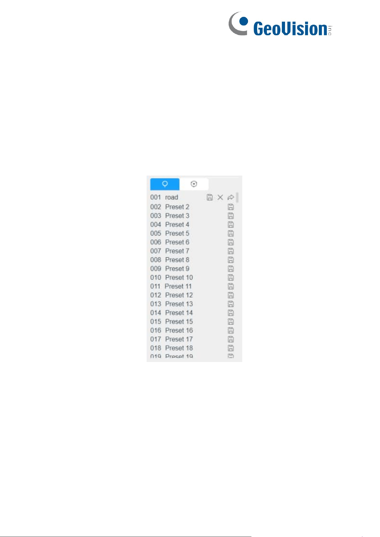
6.1.2 Set / Call a Preset / Patrol
A preset is a predefined image position. You can click the call button from the preset
list to quickly go to the desired image position.
Set a preset:
Note: The Preset only can be set while the display is 4R.
Step1: In the PTZ control panel, select a preset number from the preset list, and you can
also customize the preset name displayed on the screen. The patrol name displayed on
the screen will also be customized if you customize preset name and set a patrol as
shown below;
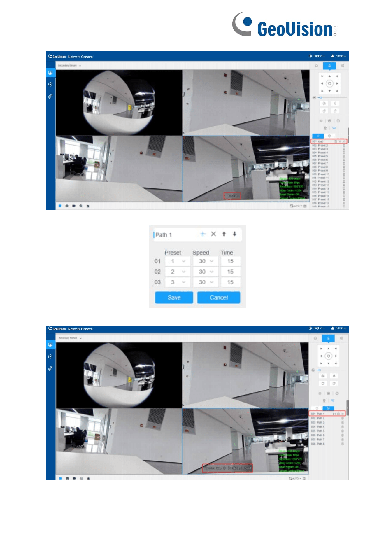
23
Step2: Use the PTZ control buttons to move the lens to the interested position;
24
Step3: Click to save the setting of the current preset;
Step4: Click to delete the chosen preset.
Note: Up to 300 presets can be configured (18 presets are not modifiable). Up to 300
presets can be configured (for each regional view channel).
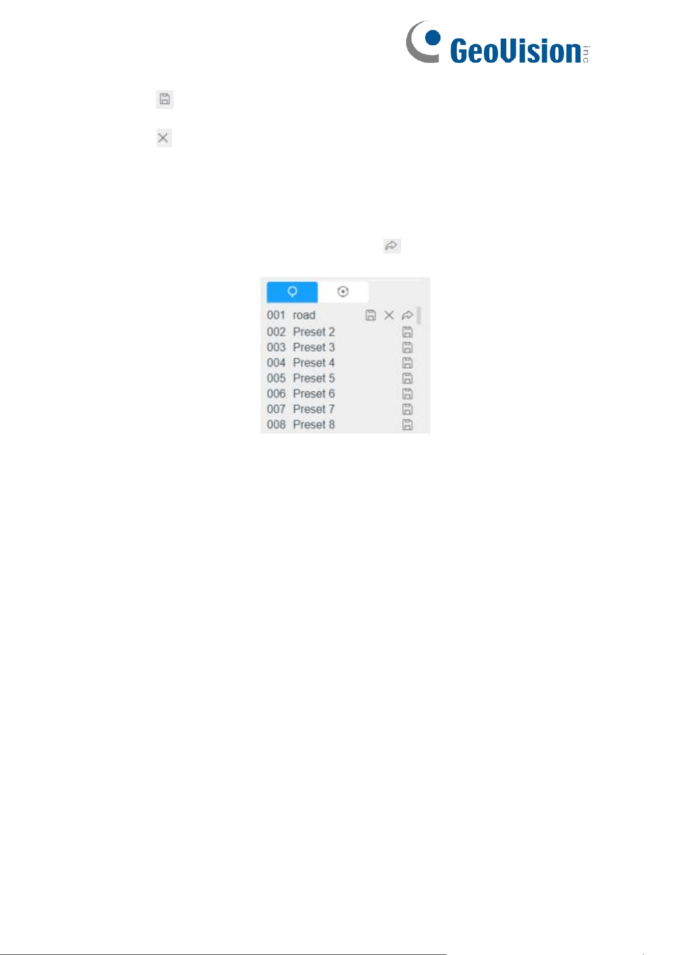
Calling a preset:
Select a defined preset from the preset list and click to call the preset.
25
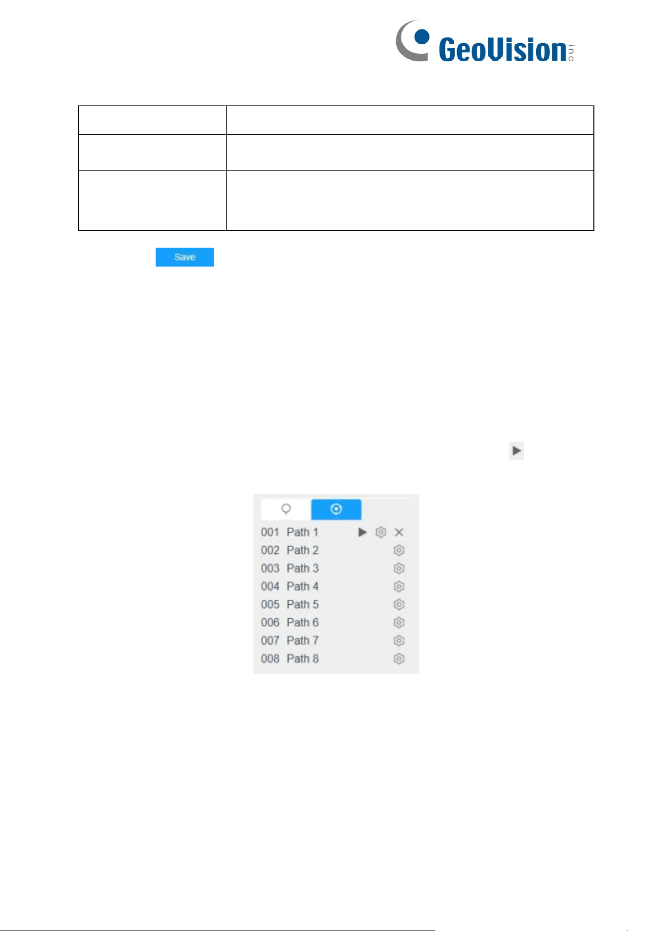
Set / Call a patrol
A patrol is a memorized series of preset function. It can be configured and called on the
patrol setting list. You can customize up to 8 patrols and it can be configured with 48
presets. Before configuring the patrol, you should make sure that the presets you want
to add to the patrol have been defined.
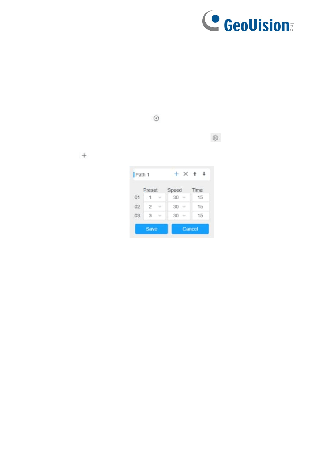
Set a patrol:
Step 1: In the PTZ control panel, click to enter the patrol settings interface;
Step 2: Select a patrol number, the setting icon will appear , click it;
Step 3: Click to add presets to this patrol, as shown in the figure below;
Step 4: Configure the preset number, patrol speed and patrol time;
26
Table 5. Description of Patrol Settings
Name
Description
Patrol Speed
The speed of moving from one preset to another.
Patrol Time
The duration staying on one patrol point. The PTZ camera
moves to another patrol point after the set patrol time.
Step 5: Click to save the patrol settings.
Note:
•
Patrol Speed only works in Patrol mode.
•
Patrol Time should be 15~120s for PTZ Bullet and 0~120s for Speed Dome.
Call a patrol:
In the PTZ control panel, select a defined patrol from the patrol list, and click to call
the patrol, as shown below.
Note: The three buttons behind the Patrol list means: Play, Set and Delete.
27
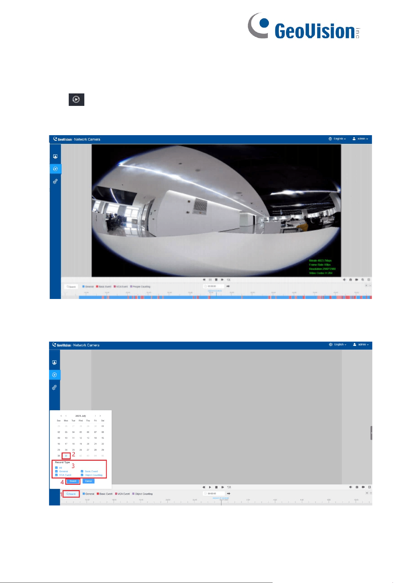
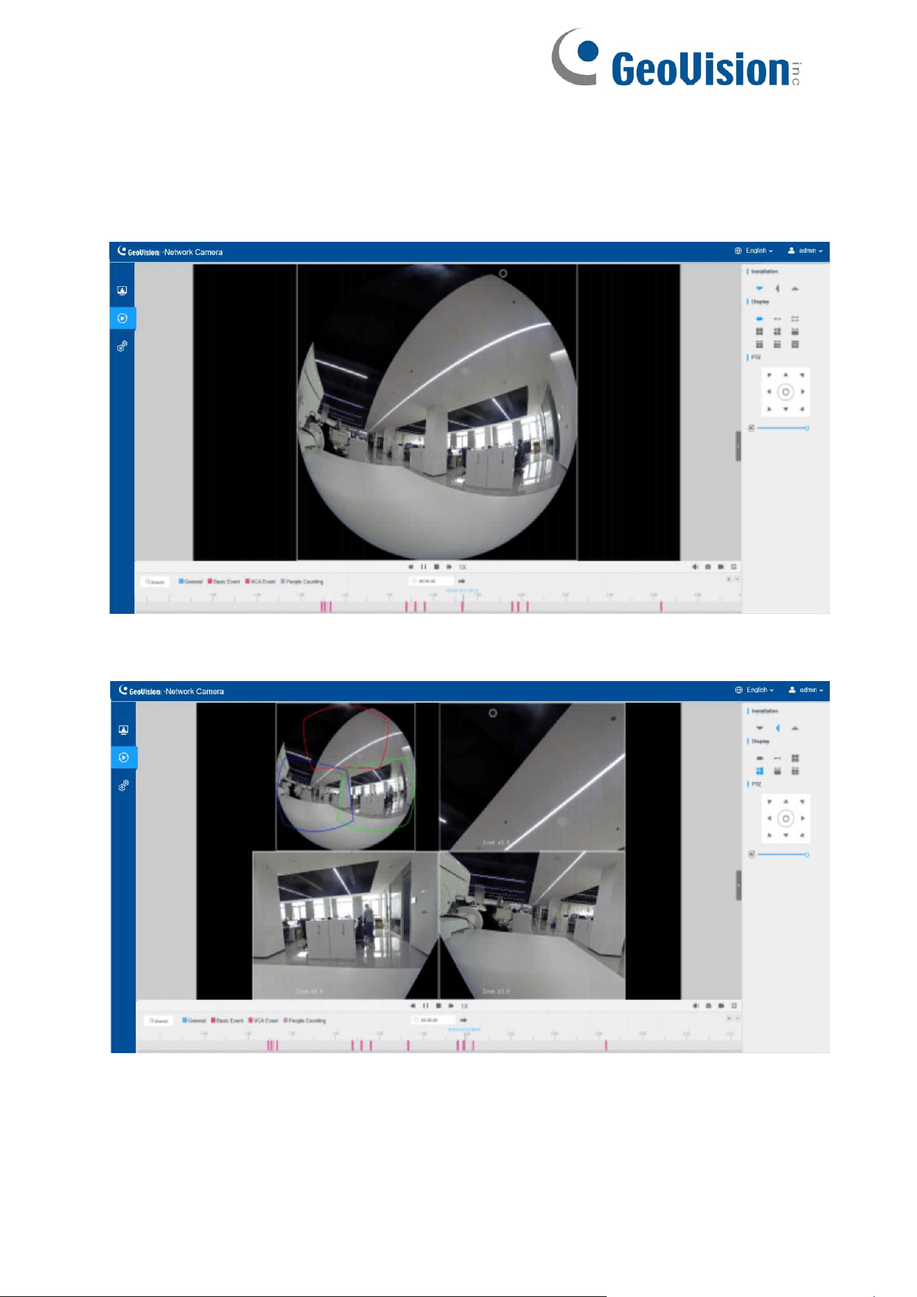
Chapter 7. Playback
Click to enter playback interface. In this part, you can search and playback the
recorded video files stored in SD cards or NAS. The Playback interface is as below:
Step 1: Click the “Search” button, choose the data and record type when the window
pops up.
28
Step 2: The timeline displays the video files for the day and show different colors
according to selected record type. Drag the progress bar with the mouse to locate
the exact playback point as needed.
Note: You can also input the time and click to locate the playback point
in the filed. You can also click to zoom out/in the
progress bar.
Step: Click to play the video files found on this date. The toolbar on the button
of playback interface can be used to control playing progress.
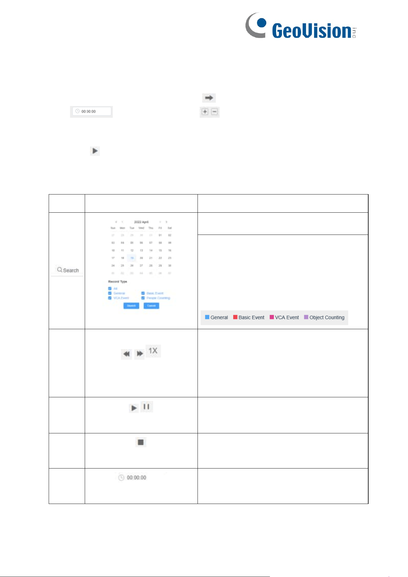
Table 6. Description of the buttons
No.
Parameter
Description
Choose date to search recorded videos.
Search the recorded videos by record type
(All/General/Basic Event/VCA
Event/People Counting). The timeline will
show different colors according to selected
record type as below:
1
/ /
Speed Down/Speed
Up/Speed
Adjust the speed of video playback.
Speed Down: Includes 0.5X and 0.25X for
Play.
Speed Up: Includes 2X and 4X for Play.
Speed: The default playback speed is 1X
2
/
Play/Pause
Play/Pause the video.
3
Stop
Stop the video.
4
Search Time
Select the time that want to locate.
29
5
Jump
Go To.
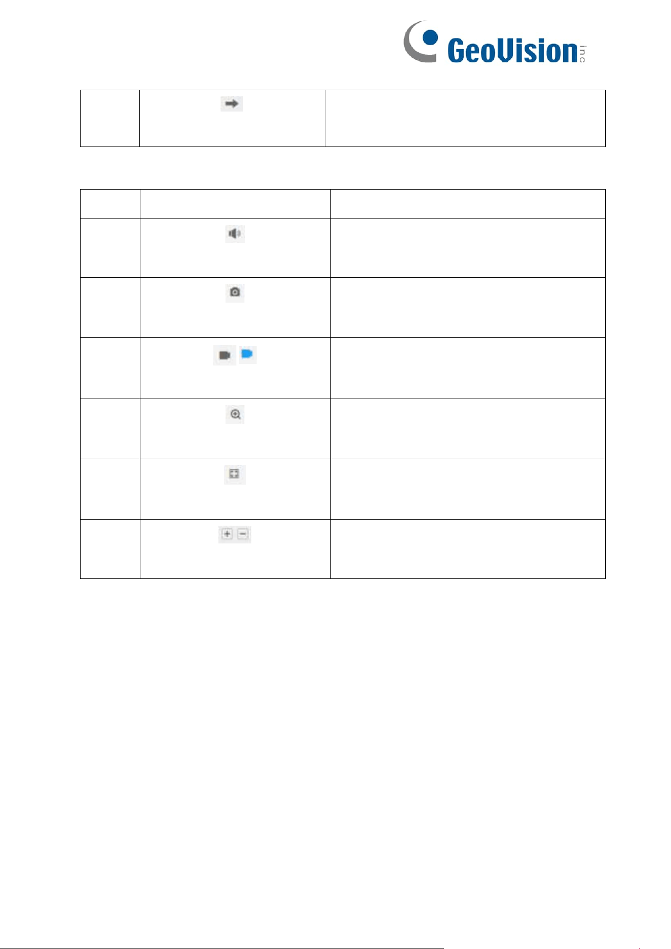
Table 7. Description of the buttons
No.
Parameter
Description
1
Mute
Click to enable the audio.
2
Snapshot
Click to take a snapshot.
3
/
Start/Stop recording
Click to start/stop recording.
4
Digital Zoom
Click to zoom on/off.
5
Full Screen
Full Screen.
6
Time Expand/Narrow
Time narrow/expand.
30
Step 4: If the recording contains the original fisheye view (1O), it supports client-side
dewarping based on the original view in the playback interface. Click to play the video
files, then you can select different installation modes and display modes as shown below.
It also supports PTZ function for panoramic view and regional views.
31
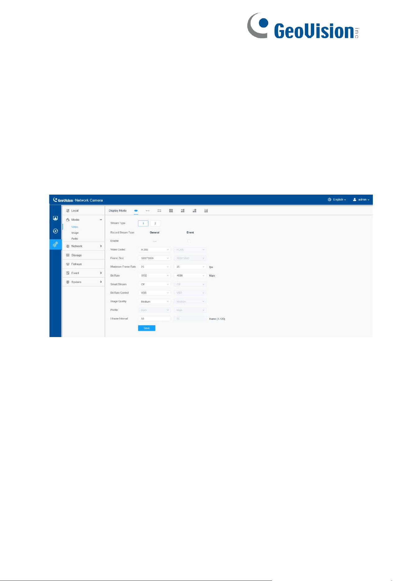
Chapter 8. Settings
8.1 Media
8.1.1 Video
Stream parameters can be set in this module, adapting to different network
environments and demands.
Multi-Channel Mode:
32
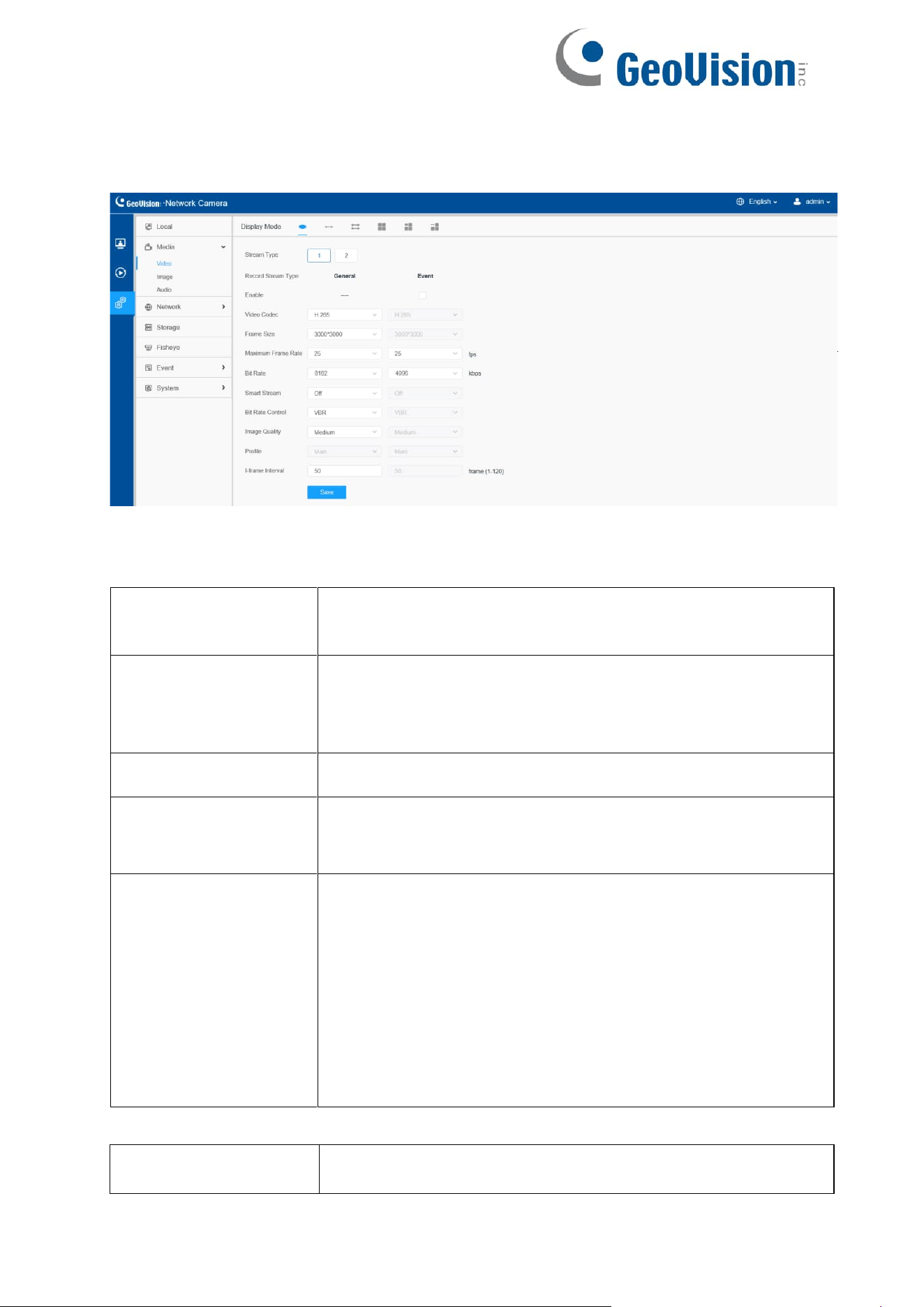
Bundle-Stream Mode:
Table 8. Description of the buttons
Parameters
Function Introduction
Channel
(Only for Multi-
Channel Mode)
The number of channels is variable according to the selected
display mode. 1O and 1P display one channel. 2P displays
two channels. 4R, 1O3R and 1P3R display four channels.
1O1P3R displays five channels.
Display Mode
1O/1P/2P/4R/1O3R/1P3R are available
Stream Type
(Only for Multi-
Channel Mode)
Primary Stream/Secondary Stream are available.
Record Stream Type
General & Event are available only for Primary Stream.
General refers to continuous record video, while Event
includes events that can trigger alarms, such as Motion,
Exception, LPR and so on.
This item can separately set different bit rate and frame rate
for different Recording Stream Types. If user chooses Event,
video will be recorded according to the configuration of video
stream type when an event happens, thereby greatly reducing
the recording storage space.
Parameters
Function Introduction

33
Enable Event Stream
This item is optional only if you selected the Event.
Video Codec
H.265/H.264 are available.
Frame Size
For Multi-Channel Mode:
4000*3000, 3000*3000, 2560*2560, 1920*1920,
1280*1280,1280*960, 1024*1024, 720*720, 320*320 are
available frame size for original fisheye view in 1O.
2560*2560, 2560*640, 1920*1920, 1920*480, 1280*1280
are available frame size for original fisheye view in 1O3R
and 1O1P3R.
3000*752, 2560*, 2560*640, 1920*480, 1280*320, 960*240
are available frame size for 360° panoramic view in 1P, 1P3R
and 1O1P3R.
2560*640, 1920*480 are available frame size for 360°
panoramic view in 1O1P3R.
3000*1680, 2688*1520, 2592*1460, 1920*1080, 1280*720
are available frame size for two 180° panoramic views in 2P.
1920*1080, 1280*720, 640*480 are available frame size for
regional view.
For Bundle-Stream Mode:
4000*3000, 3000*3000, 2560*2560, 2592*1944, 1944*1944,
1920*1920, 1536*1536, 1280*1280 are available frame size
for 1O.
3000*752, 2592*648, 2560*640, 1920*480, 1280*320 are
available frame size for
1P.
3000*1680, 2688*1520, 2592*1460, 1920*1080, 1280*720
are available frame size for 2P.
4000*3000, 3840*2160, 3072*1728,2592*1944, 2304*1296
are available frame size for 4R, 1O3R and 1P3R.
Note: The camera supports up to 3000*3000 (12MP fisheye
model) of Frame Size.
Maximum Frame Rate
Maximum refresh frame rate of per second and it is variable
according to the mode.

34
Parameter
Function Introduction
Bit Rate
Transmitting bits of data per second, this item is optional only if
you select the H.265/
H.264
Set the bitrate to 32~16384 Kbps. The higher value
corresponds to the higher video quality, and the
higher bandwidth is required as well.
Smart Stream
Optional to turn On/Off Smart Stream mode. Smart Stream
mode remarkably reduces the bandwidth and the data storage
requirements for network cameras while ensuring the high
quality of images, and it is a 10-level adjustable codec.
Level: Level 1~10 is available as needed.
Bit Rate Control
CBR: Constant Bitrate. The rate of CBR output is constant.
VBR: Variable Bitrate. VBR files vary the amount of output data
per time segment.
Image Quality
Low/Medium/High are available, this item is optional only if you
select VBR.
Profile
The option is for H.264, Main/High/Base can be selected as
needed.
I-frame Interval
Set the I-frame interval to 1~120, 50 for the default. This item
is optional only if you select the H.265/H.264. The number
must be a multiple of the number of frames.
35
8.1.2 Image
General settings of image including the image adjustment, day/night setting and image
enhancement can be set in this module. OSD (On Screen Display) content, privacy
mask and video time can be displayed to rich the image information.
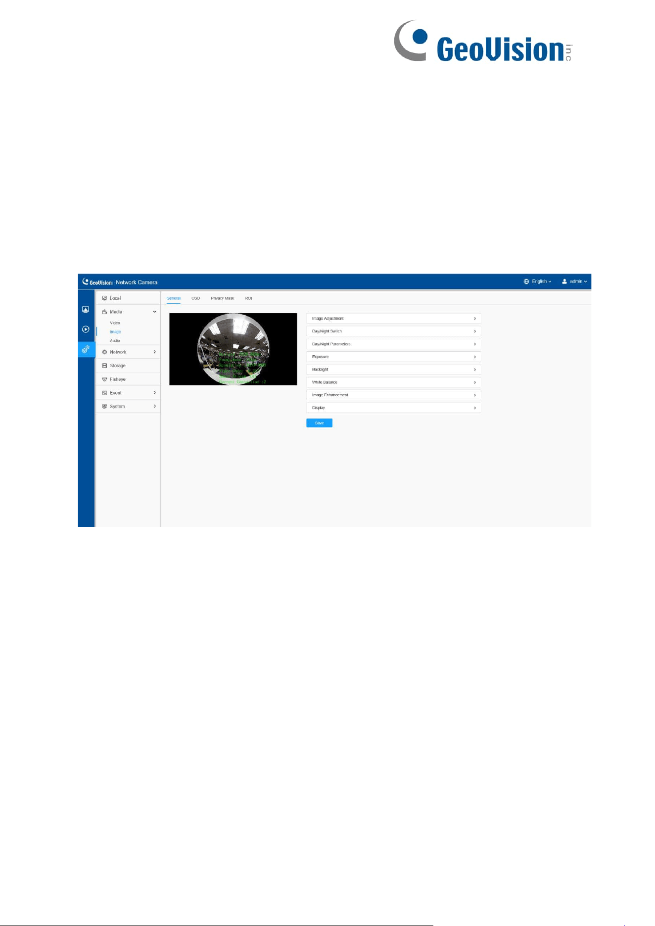
8.1.2.1 General
General settings of image including the image adjustment, day/night switch, day/night
parameters, exposure, backlight, white balance, image enhancement and Display can
be set in this module.
36
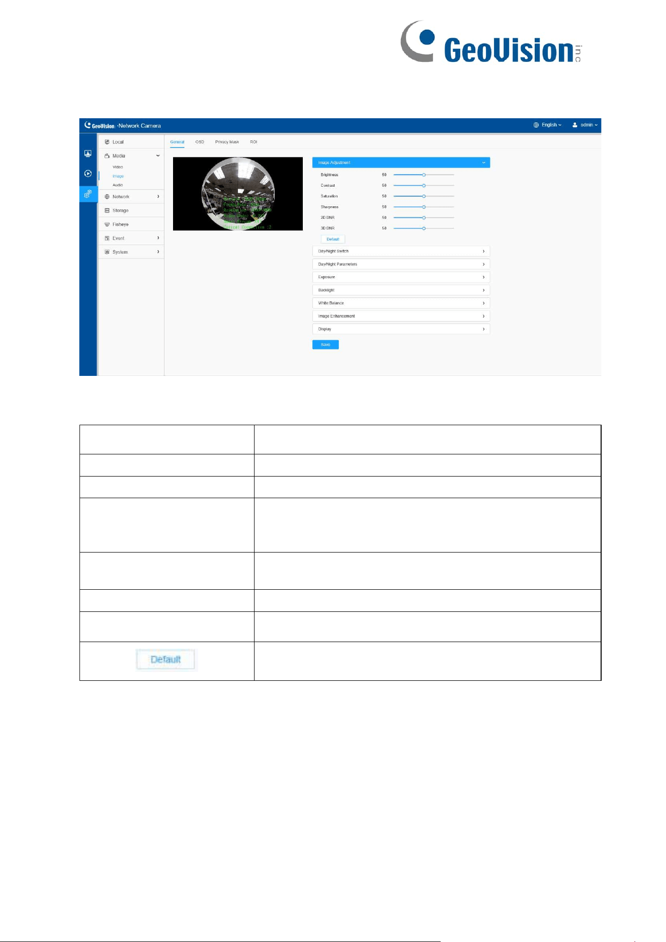
[Image Adjustment]
Table 9. Description of the buttons
Parameters
Function Introduction
Brightness
Adjust the Brightness of the scene.
Contrast
Adjust the color and light contrast.
Saturation
Adjust the Saturation of the image. Higher Saturation
makes colors appear “purer” while lower one appears
more “wash-out”.
Sharpness
Adjust the Sharpness of image. Higher Sharpness sharps
the pixel boundary and makes the image looks “clearer”.
2D DNR
Adjust the noise reduction level.
3D DNR
Restore brightness, contrast and saturation to default
settings.
Adjust the Brightness of the scene.
37
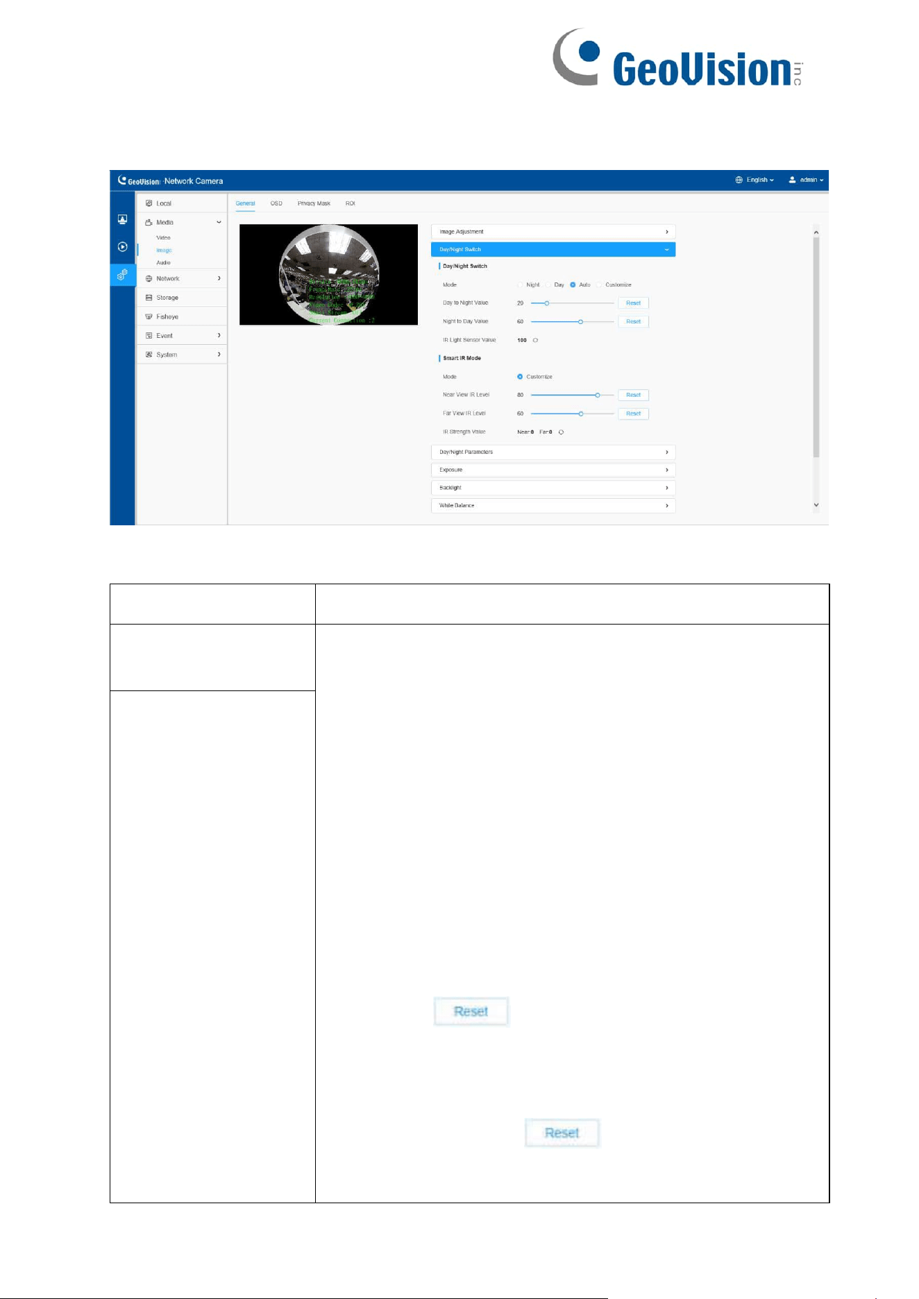
[Day/Night Switch]
Table 10. Description of the buttons
Parameters
Function Introduction
Day/Night Switch
Night Mode: Shown in live view based on Night Mode settings.
Day Mode: Shown in live view based on Day Mode settings.
Auto Mode: Shown in live view based on environment,
set the sensitivity for switching Day Mode to Night
Mode, or Night Mode to Day Mode.
Customize: Shown in live view based on your own settings’
time to start/end Night
Mode.
Note: There are several parameters such as Exposure
Level, Maximum Exposure Time and IR-CUT Interval, etc.,
associated with the modes.
Day to Night Value: You can set the sensitivity for switching
Day Mode to Night Mode. When IR Light Sensor Current Value
is lower than this value, it will switch Day Mode to Night Mode.
You can click to reset the value to 36.
Night to Day Value: This is the sensitivity for switching
Night Mode to Day Mode. When IR Light Sensor Current
Value is higher than this value, it will switch Night Mode to
Day Mode. You can click to reset the value to 82.
IR Light Sensor Value: The current value of the IR light
sensor.
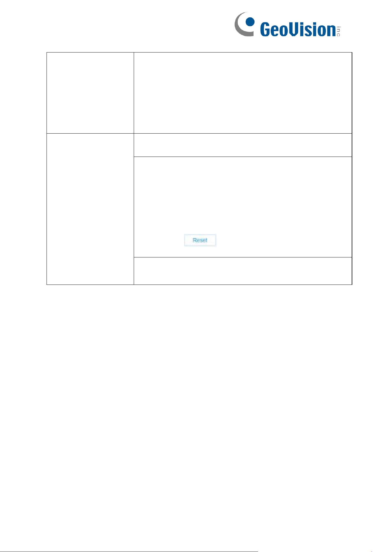
Day/Night Switch
38
Note: The three buttons are optional only if you select Auto
Mode.
Start Time of Night: You can set the time for start the Night
Mode.
End Time of Night: You can set the time for start the Day
Mode.
Note: Start/End Time of Night are optional only if you select
Customize Mode.
Smart IR Mode
Support to set the strength of the IR to Customize to achieve
the best effect.
Near View IR Level: Adjust the light strength of Low-Beams
LED light level from 0 to 100.
Far View IR Level: Adjust the light strength of High-Beams
LED light level from 0 to 100.
Note:
Near/Far View IR Level are optional only if you
select Customize Mode of Smart IR.
Click to reset the light strength to 50.
IR Strength Value: The current value of Low-Beams LED
and High-Beams LED light value.
39
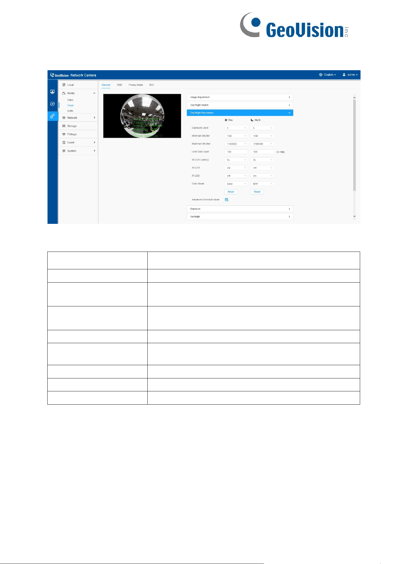
[Day/Night Parameters]
Table 11. Description of the buttons
Parameters
Function Introduction
Exposure Level
Level 0~10 is available to meet your need.
Minimum Shutter
Minimum Shutter is the same as Maximum Exposure
Time. Set the minimum Shutter to 1~1/100000s.
Maximum Shutter
Maximum Shutter is the same as Minimum Exposure
Time. Set the maximum Shutter to 1~1/100000s.
IR-CUT Latency
The interval time of switching one mode to another.
Limit Gain Level
Set the Limit Gain Level to 1~100.
IR-CUT
Turn on/off IR-CUT.
IR LED
Turn on/off IR-LED.
Color Mode
Select B/W or Color mode.
40
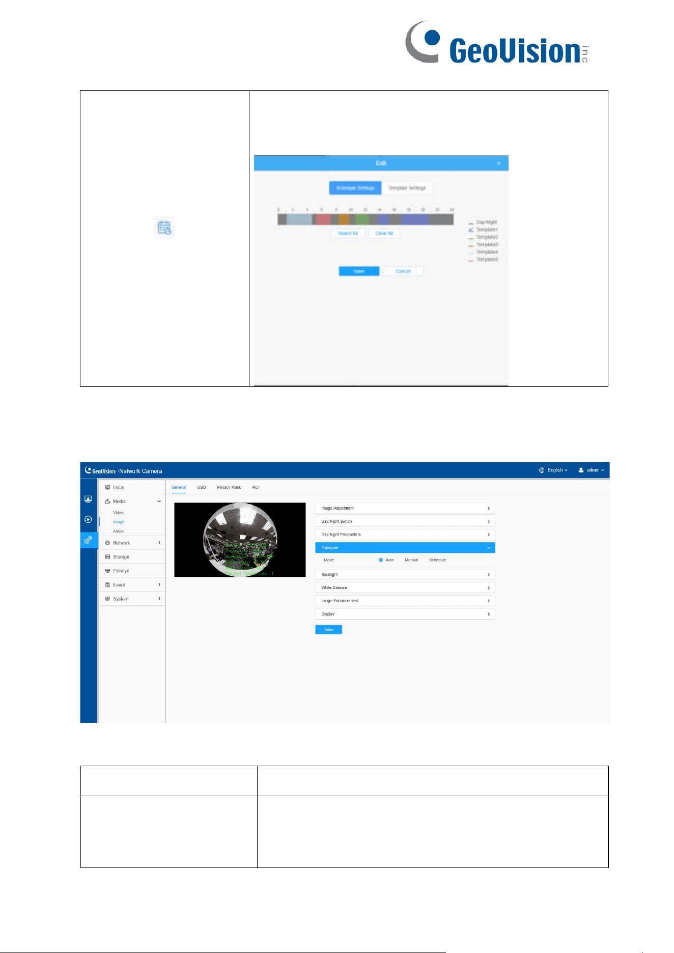
Advanced Schedule Mode
Here you can customize your special demands for
different time, then the Day mode and Night mode will
switch automatically according to your settings.
[Exposure]
Table 12. Description of the buttons
Parameters
Function Introduction
Exposure Mode
Auto Mode, Manual Mode and Schedule Mode are
available.
Auto Mode: The camera will adjust the brightness
according to the light environment automatically.
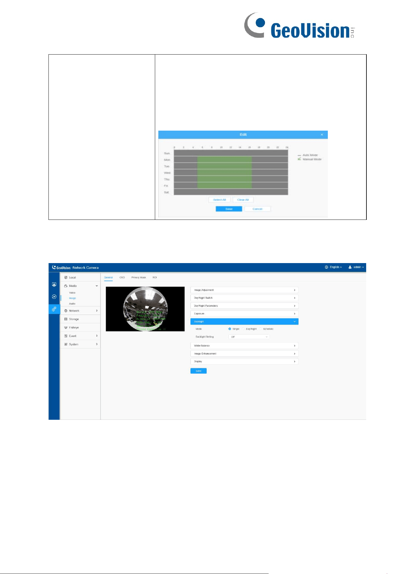
41
Manual Mode: The camera will adjust the brightness
according to the value you set, you can set the exposure
time from 1~1/100000s, the higher the value is, the
brighter the image is.
Schedule Mode: You can customize the schedule to
enable/disable Auto Mode and Manual Mode.
[Backlight]
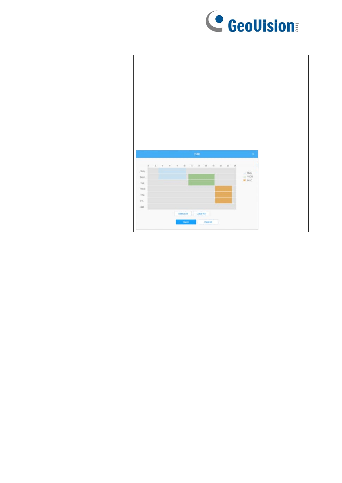
42
Table 13. Description of the buttons
Parameters
Function Introduction
Backlight Mode
Single Mode: Set single mode for BLC/WDR/HLC.
Day/Night Mode: Support BLC/WDR/HLC on Day
Enhancement Mode/Night Enhancement Mode
separately.
Schedule Mode: Set schedule mode for
BLC/WDR/HLC. You can customize the schedule to
enable/disable BLC/WDR/HLC mode.
43
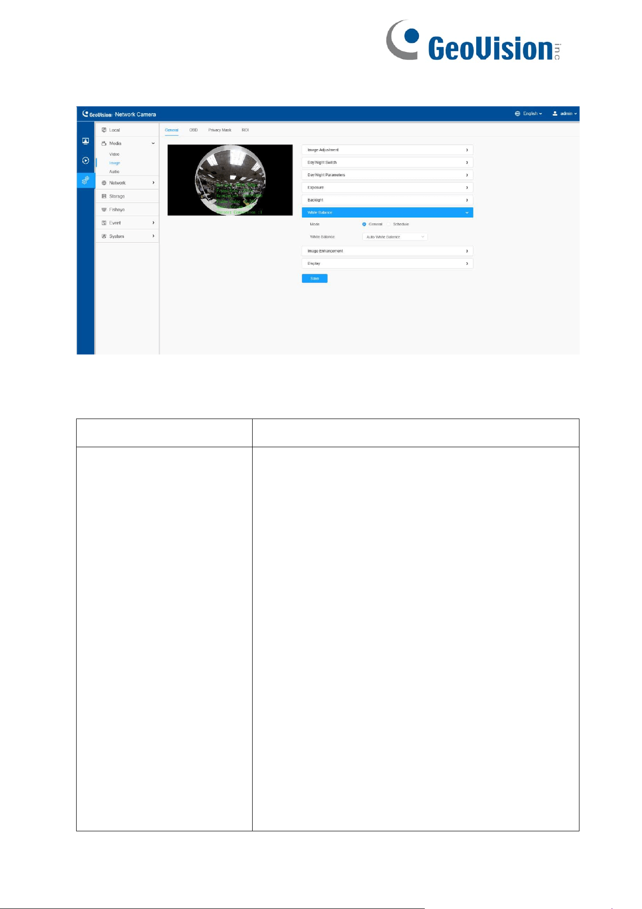
[White Balance]
Table 14. Description of the buttons
Parameters
Function Introduction
White Balance
To restore white objects, removed color distortion
caused by the light of the environment.
Auto White Balance: This option will automatically
enable the White Balance function.
Manual White Balance: Set Red Gain Level and Blue
Gain Level manually.
Incandescent Lamp: Select this option when
light is similar with incandescent lamp.
Warm Light Lamp: Select this option when light is
similar with warm light lamp.
Natural Light: Select this option when there is no other
light but natural light.
Fluorescent Lamp: Select this option when light is
similar with Fluorescent Lamp.
44
Schedule mode: Select this option that you can
customize the schedule to enable/ disable above
modes.
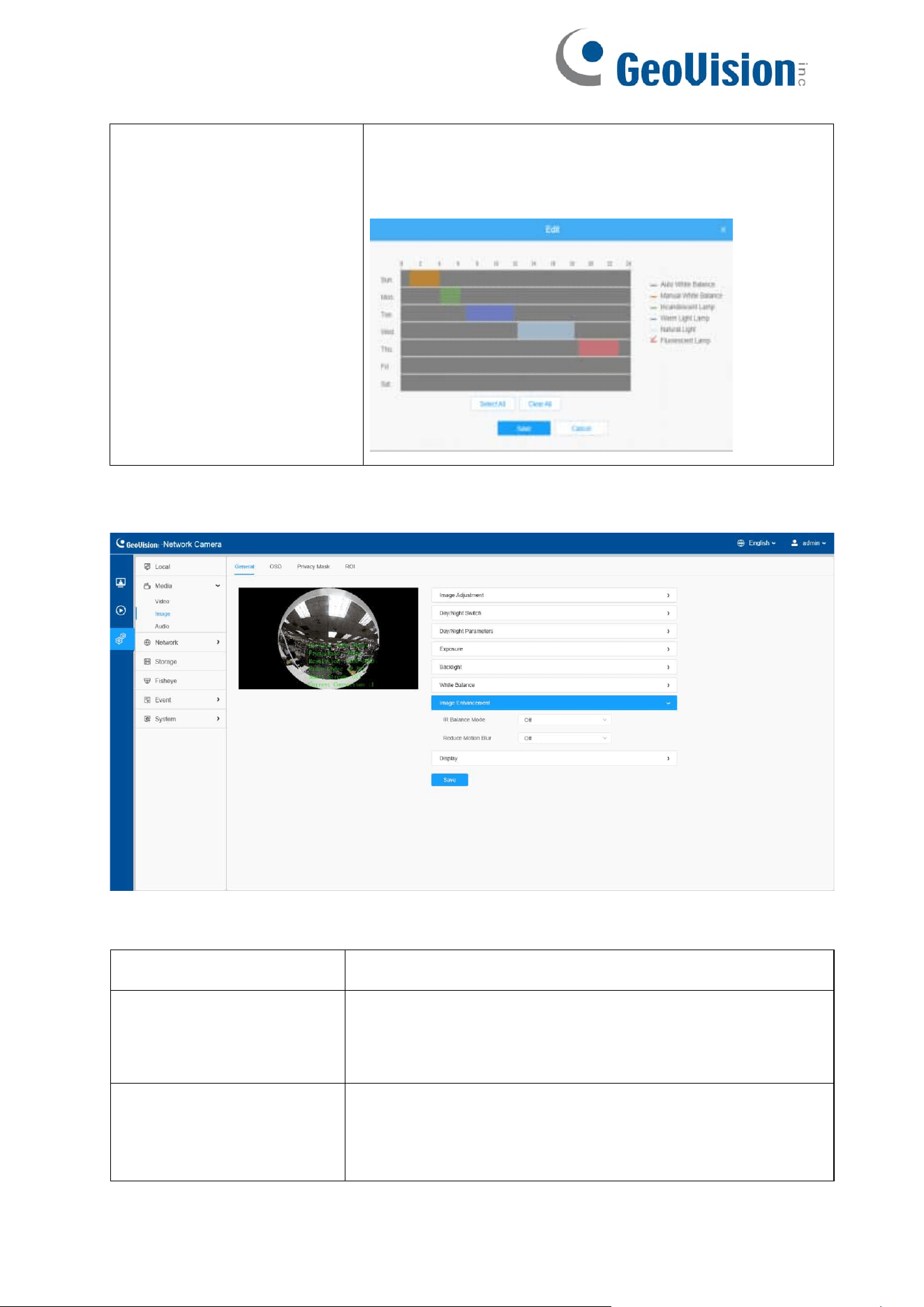
[Image Enhancement]
Table 15. Description of the buttons
Parameters
Function Introduction
IR Balance Mode
There is an option to turn On/Off the IR LED.
IR Balance Mode would avoid the problem of
overexposure and darkness, and the IR LED will change
according to the actual illumination.
Reduce Motion Blur
Enable this function to reduce the motion blur of
objects effectively. You can adjust the deblur
level from 1 to 100.
45
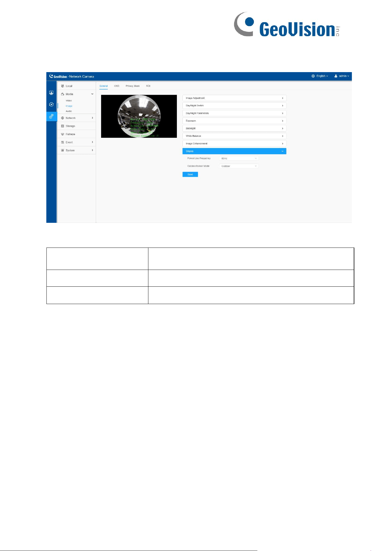
[Display]
Table 16. Description of the buttons
Parameters
Function Introduction
Power Line Frequency
60Hz and 50Hz are available.
Outdoor/Indoor Mode
Select indoor or outdoor mode to meet your needs.
46
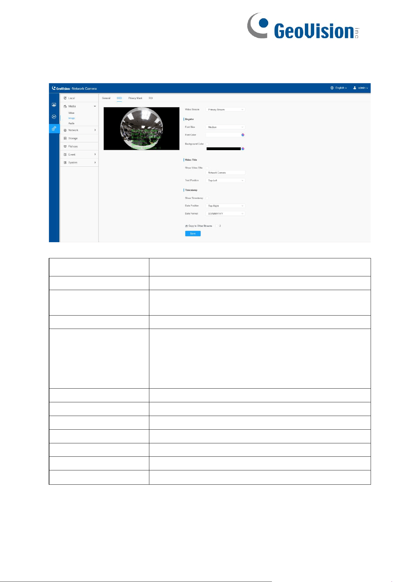
8.1.2.2 OSD
Table
17.
Description
of
the
buttons
Parameters
Function Introduction
Video Stream
Enable to set OSD for primary stream and secondary stream.
Font Size
Smallest/Small/Medium/Large/Largest/Auto are available for
title and date.
Font Color
Enable to set different color for title and date.
Background Color
Enable to set different colors for display information
background on screen.
You can set different colors for font and background of
image, then the image OSD will show as below:
Show Video Title
Check the check box to show video title.
Video Title
Customize the OSD content.
Text Position
OSD display position on the image.
Show Timestamp
Check the checkbox to display date on the image.
Date Position
Date display position on the image.
Date Format
The format of date.
Copy to Other Streams
Copy the settings to other streams.
47
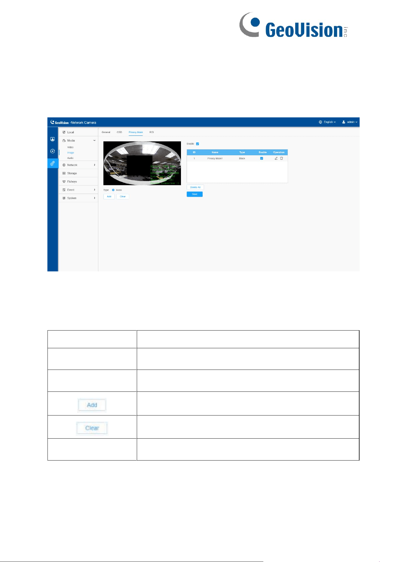
8.1.2.3 Privacy Mask
Privacy mask enables to cover certain areas on the live video to prevent certain
spots in the surveillance area from being viewed and recorded.
[Privacy Mask]
Note:
• For the fisheye model, it only supports black color for Privacy Mask.
Table 18. Description of the buttons
Parameters
Function Introduction
Enable
Check the check box to enable the Privacy Mask function.
Type
Black mask type is available for fisheye camera.
Drew a privacy area on the live video as needed.
Clear the area you drew on the live video.
Delete All
Clear all areas you drew before.
48
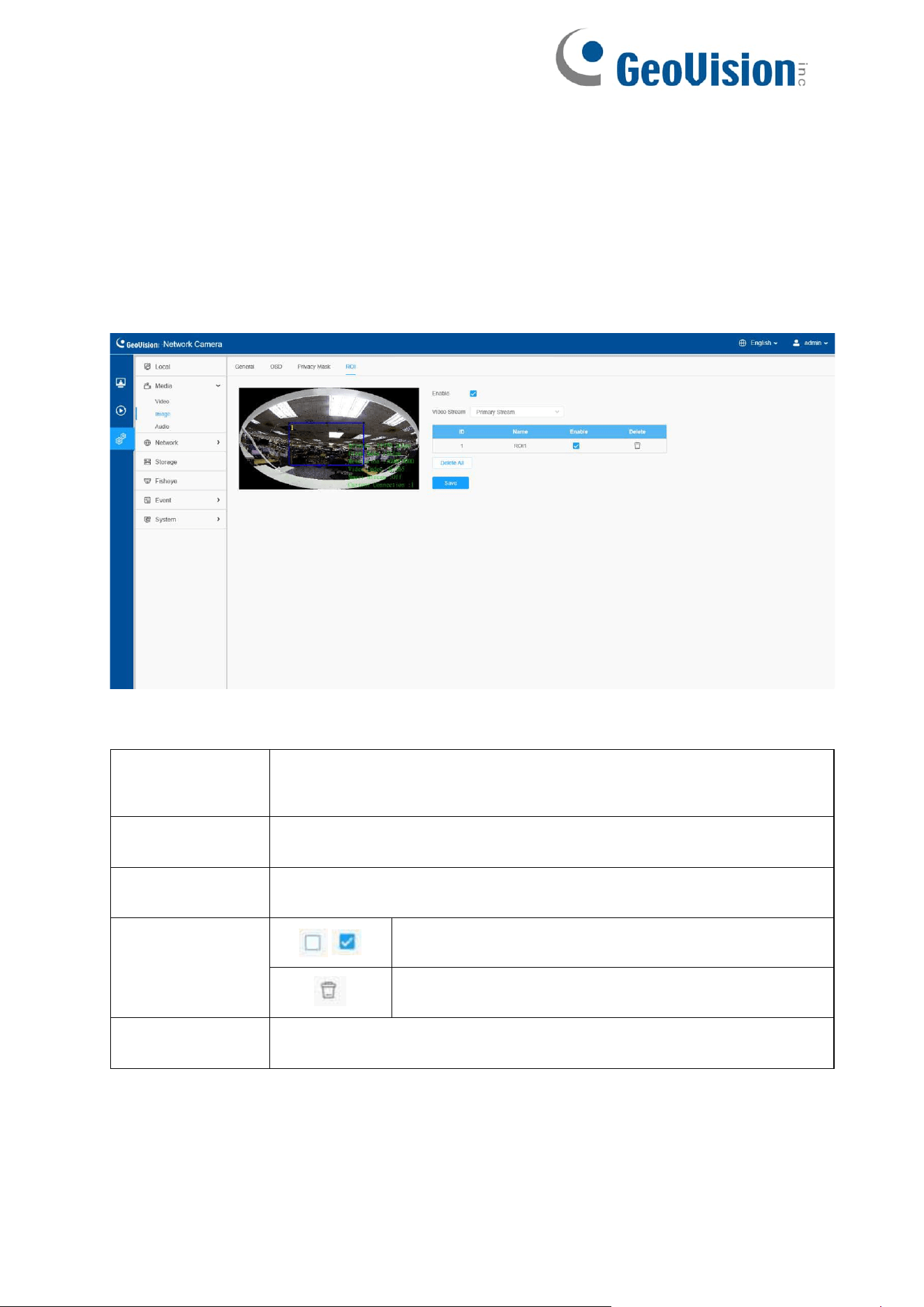
8.1.2.4 ROI
Region of interest (often abbreviate ROI), is a selected subset of samples within a
dataset identified for a particular purpose. Users can select up to 8 key regions of a
scene to transmit through separate streams for targeted preview and recording.
By using ROI technology, more than 50% of bit rate can be saved and therefore less
bandwidth demanded and the storage usage reduced. So according to this, you can set
a small bit rate for high resolution.
Table 19. Description of the buttons
Parameters
Function Introduction
Enable
Check the checkbox to enable the ROI function.
Video Stream
Choose the Video Stream.
ROI
/
Enable/disable the selected ROI areas.
Delete the selected ROI areas.
Delete All
Clear all areas you drew before.
49
Note:
You can set a low bit rate. For example, you can set a bit rate with 512
Kbps and a resolution with 1080P, then you can see the image quality of
ROI is clearer and more fluent than the other region.
ROI function will be disabled when the resolution of fisheye camera is 4 K
and above.
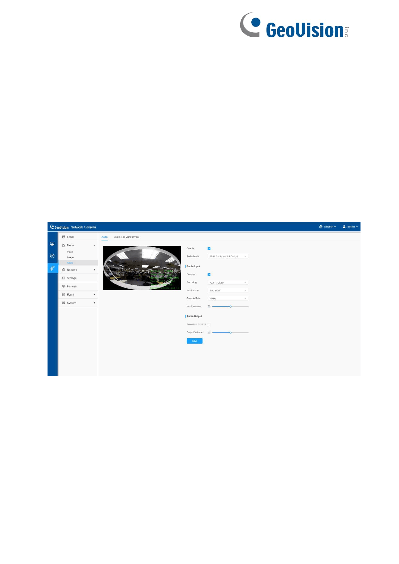
8.1.3 Audio
8.1.3.1 Audio
This audio function allows you to hear the sound from the camera or transmit your
sound to the camera side. A two-way communication is also possible to be achieved
with this feature. Alarm can be triggered when the audio input is above a certain alarm
level you set, and configured audio can be played when an alarm occurs.

50
Table 20. Description of the buttons
Parameters
Function Introduction
Enable
Check on the checkbox to enable audio feature.
Audio Mode
Audio Input/Audio Output/Both Audio Input & Output are
optional.
Audio Input
Denoise: Set it as On/Off. When you set the function on, the
noise detected can be filtered.
Encoding: G.711-ULaw and G.711-ALaw are available
Sample Rate: 8KHz, 16KHz, 32KHz, and 48KHz are available.
Input Volume: Input audio gain level, 0-100.
Audio Output
Auto Gain Control: This function is only for H.265 series,
improve the quality of audio.
Output Volume: Adjust volume of output.
51
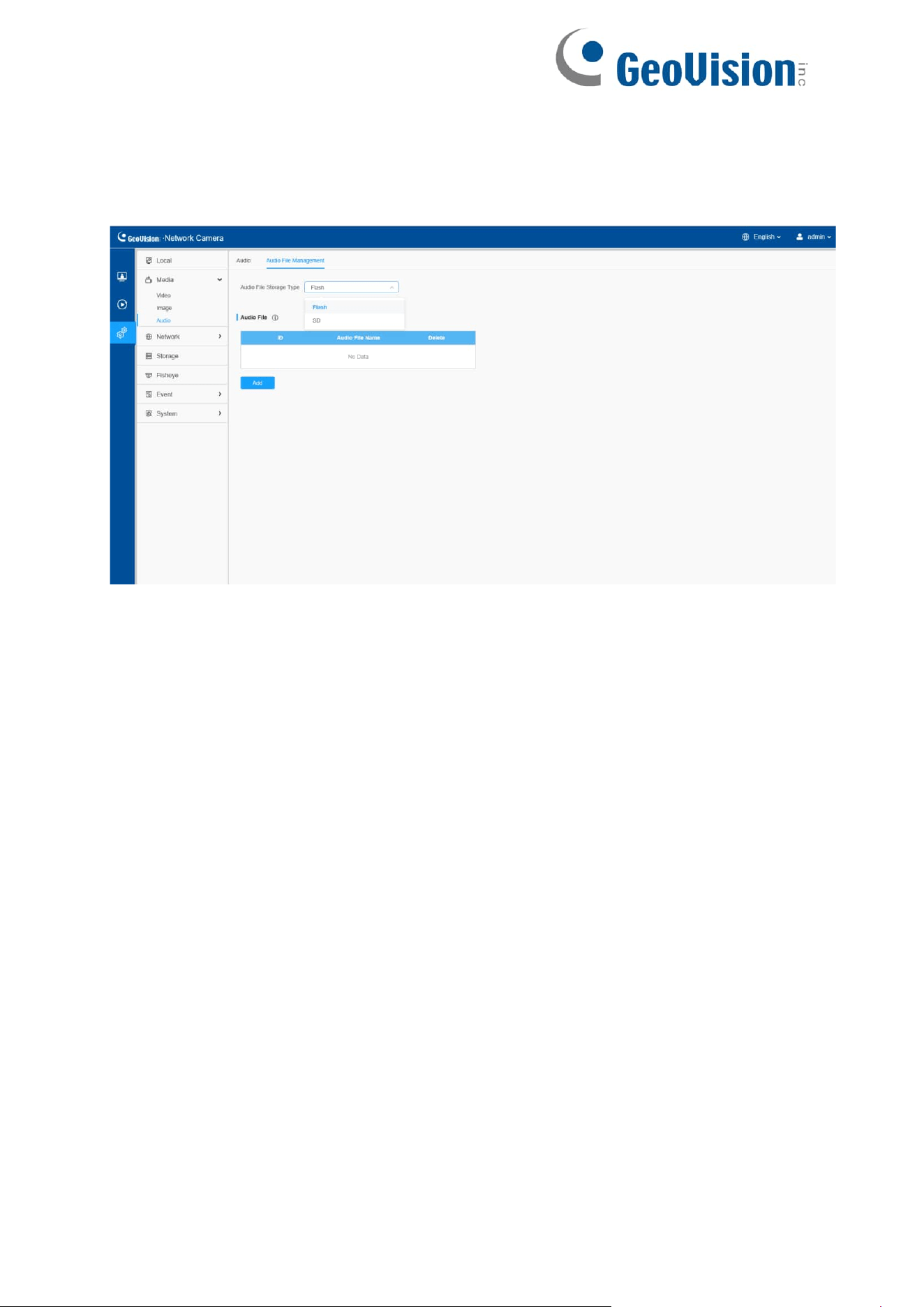
8.1.3.2 Auto File Management
You can upload up to 5 audio files manually to Flash or SD Card on the Audio web page
and you can also edit the audio file’s name when upload.
Note:
Only support ‘.wav’ audio files with codec type PCM/PCMU/PCMA, 64kbps
or 128 kbps and no more than 500k.
52
8.2 Network
8.2.1 Basic
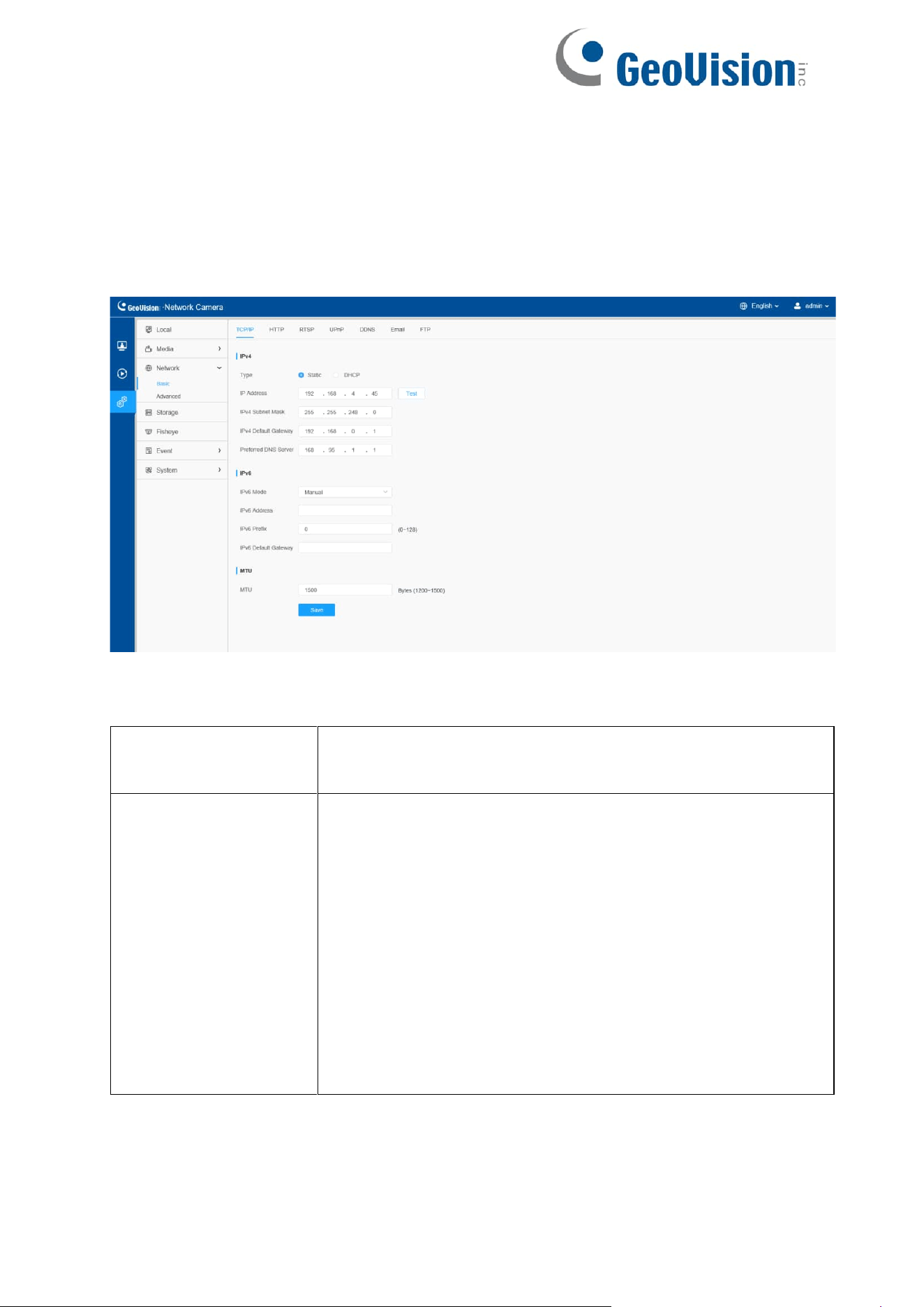
8.2.1.1 TCP/IP
Table 21. Description of the buttons
Parameters
Function Introduction
IPv4
Type: Static Type and DHCP Type are optional for user
to get IPv4 address automatically or use fixed IP
address.
IPv4 Address: An address that used to identify a network
camera on the network.
Note: The Test button is used to test if the IP is conflicting.
IPv4 Subnet Mask: It is used to identify the subnet where
the network camera is located.
IPv4 Default Gateway: The default router address.
Preferred DNS Server: The DNS Server translates the domain
name to IP address.
53
IPv6
IPv6 Mode: Choose different modes for IPv6:
Manual/Route Advertisement/ DHCPv6
IPv6 Address: IPv6 Address used to identify a network camera
on the network
IPv6 Prefix: Define the prefix length of IPv6 address
IPv6 Default Gateway: The default router IPv6 address
MTU
Maximum Transmission Unit. The default value is 1500.
You can customize the value from 1200 to 1500 as
needed.
Save the configuration.
54
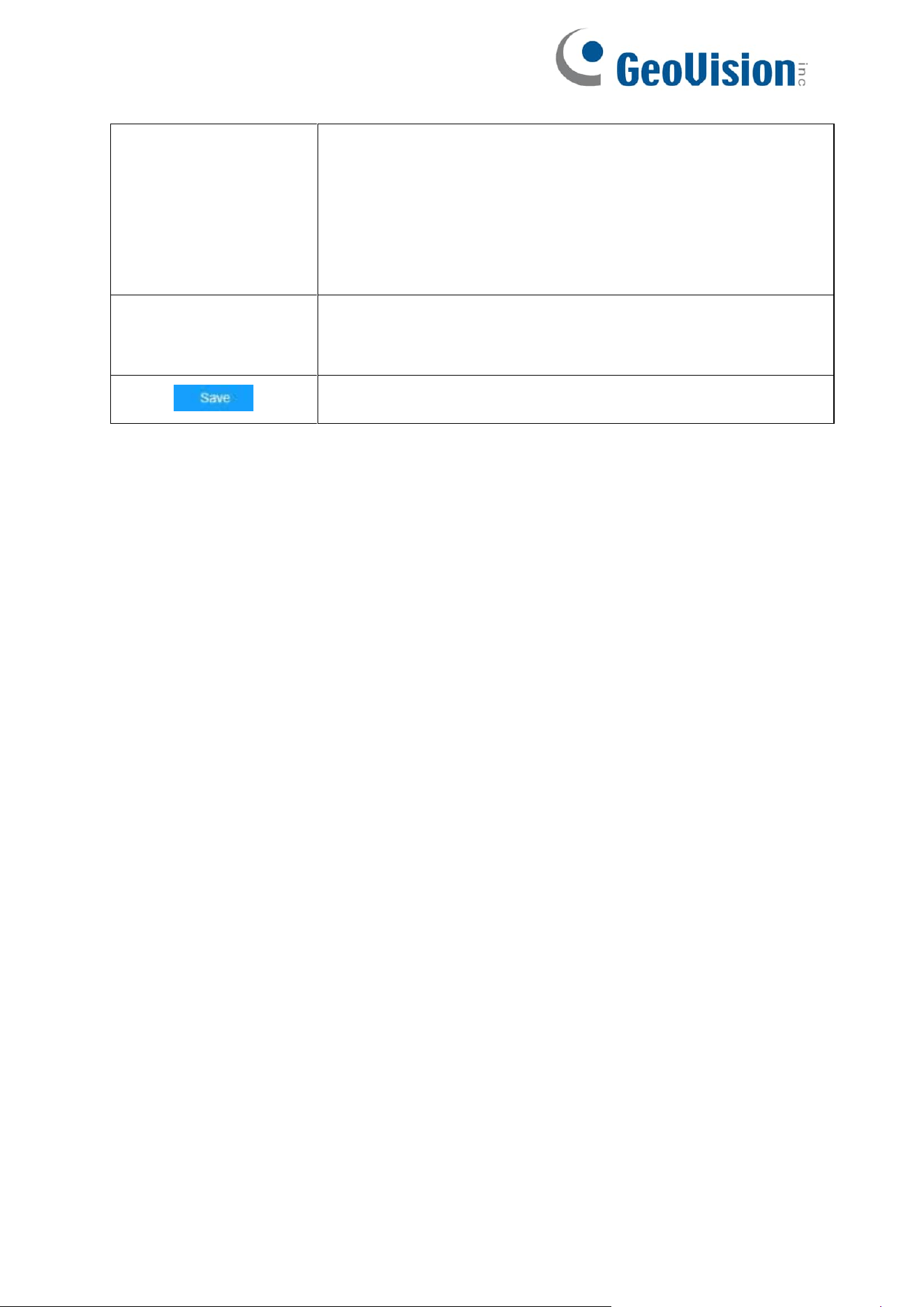
8.2.1.2 HTTP
Table 22. Description of the buttons
Parameters
Function Introduction
HTTP
Enable: Start or stop using HTTP.
Port: Web GUI login port, the default is 80, the same with
ONVIF port.
HTTPs
Enable: Start or stop using HTTPs.
Port: Web GUI login port via HTTPS, the default is 443.
Installed Certificate
Upload and set the SSL certificate.
Attributes
Installation Type
Save the configuration.
55
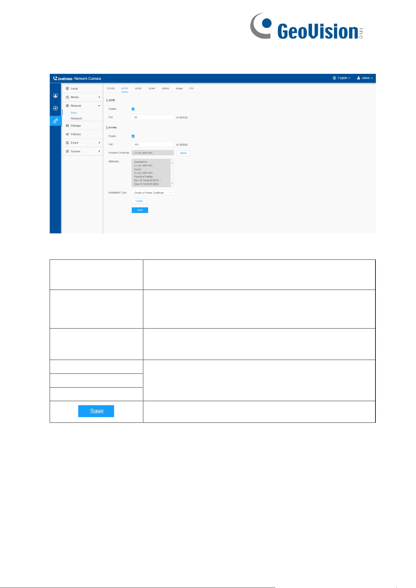
8.2.1.3 RTSP
Table 23. Description of the buttons
Parameters
Function Introduction
RTSP Port
The port of RTSP, the default is 554.
Playback Port
Playback Port The port of playback, the default is 555.
Note: Port 0 means closing playback function.
RTP Packet
There are Better Compatibility and Better Performance two
options, if your camera’s image mess up, please switch this
option.
Multicast Group
Address
Support multicast function.
QoS DSCP
The valid value range of the DSCP is 0-63.
Save the configuration.
Table 24. RTSP URL are as below:
Stream
URL
Primary Stream
rtsp://IP:RTSP Port/main
Secondary Stream
rtsp://IP:RTSP Port/sub
Channel 01
rtsp://IP:RTSP Port/main
Channel 02
rtsp://IP:RTSP Port/sub
56
Channel 03
rtsp://IP:RTSP Port/third
Channel 04
rtsp://IP:RTSP Port/fourth
Channel 05
rtsp://IP:RTSP Port/fifth
Note:
The RTSP URL for Primary Stream and Secondary Stream of fisheye
camera is optional when transfer mode is bundle-stream mode.
The RTSP URL for Channel 01/02/03/04/05 of fisheye camera is
optional when transfer mode is multi- channel mode.
DSCP refers to the Differentiated Service Code Point; and the DSCP
value is used in the IP header to indicate the priority of the data.
A reboot is required for the settings to take effect.
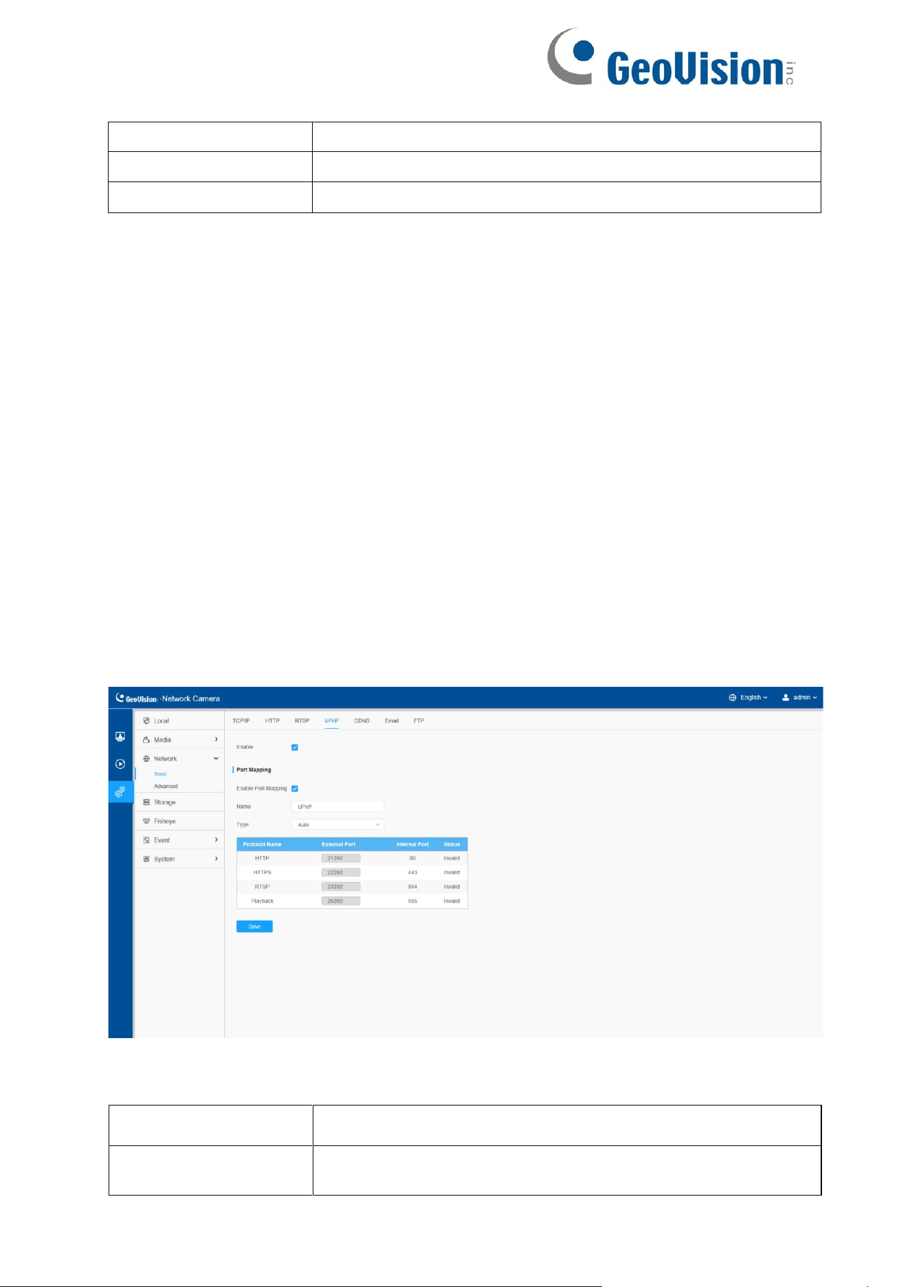
8.2.1.4 UPnP
Universal Plug and Play (UPnP) is a networking architecture that provides compatibility
among networking equipment, software and other hardware devices. The UPnP protocol
allows devices to connect seamlessly and to simplify the implementation of networks in
the home and corporate environments. With the function enabled, you don’t need to
configure the port mapping for each port, and the camera is connected to the Wide Area
Network via the router.
Table 25. Description of the buttons
Parameters
Function Introduction
Enable
Check the checkbox to enable the UPnP function.
57
Enable Port Mapping
Check the checkbox to enable the Port Mapping
Name
The name of the device detected online can be edited
Type
Auto: Automatically obtain the corresponding HTTP and
RTSP port, without any settings
Manual: Need to manually set the appropriate HTTP port
and RTSP Port. When choose Manual, you can customize
the value of the port number by yourself
Save the configuration.
58
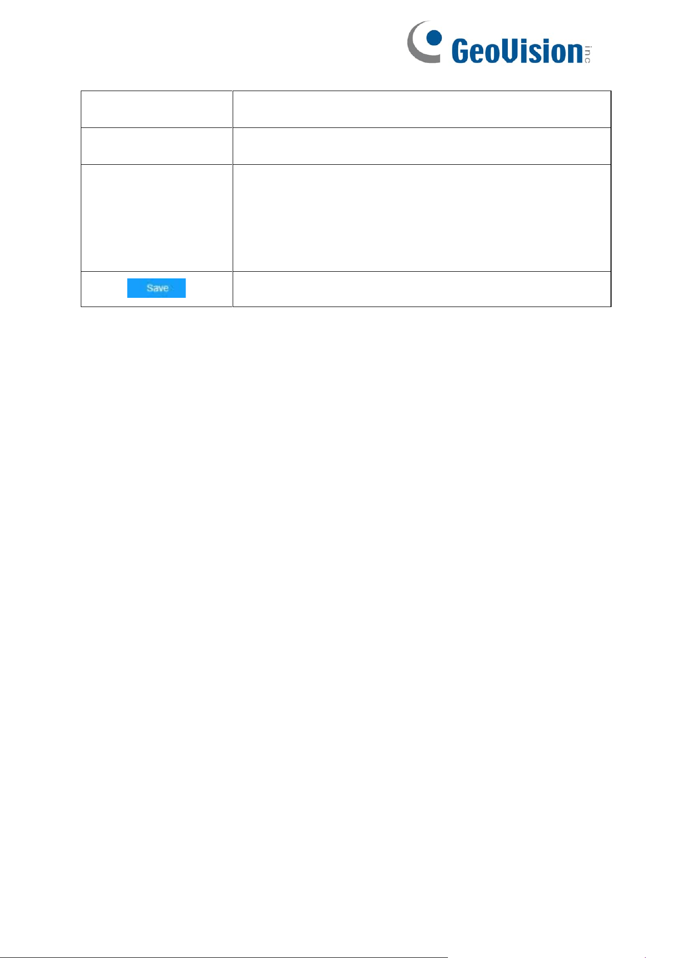
8.2.1.5 DDNS
DDNS allows you to access the camera via domain names instead of IP address. It
manages to change IP address and update your domain information dynamically. You
need to register an account from a provider.
Table 26. Description of the buttons
Parameters
Function Introduction
Enable DDNS
Check the checkbox to enable DDNS service.
Note: Recommend to enable and configure UPnP ports
which can be used directly in DDNS.
Provider
Get support from DDNS provider: freedns.afraid.org,
dyndns.org, www.no-ip.com, www.zoneedit.com.
You can also customize the provider for DDNS.
Hash
A string used for verifying, only for "freedns.afraid.org".
User name
Account name from the DDNS provider, unavailable for
"freedns.afraid.org".
59
Parameters
Function Introduction
Password
Account password, unavailable for "freedns.afraid.org".
Host name
DDNS name enabled in the account.
Status
Display DDNS running status.
Save the configuration.
Note: Make sure that the internal and the external port number of RTSP are the
same.
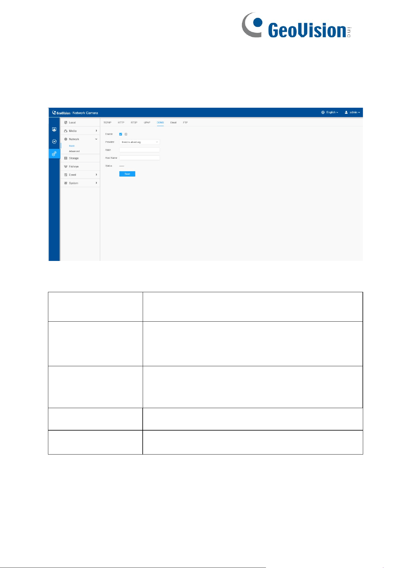
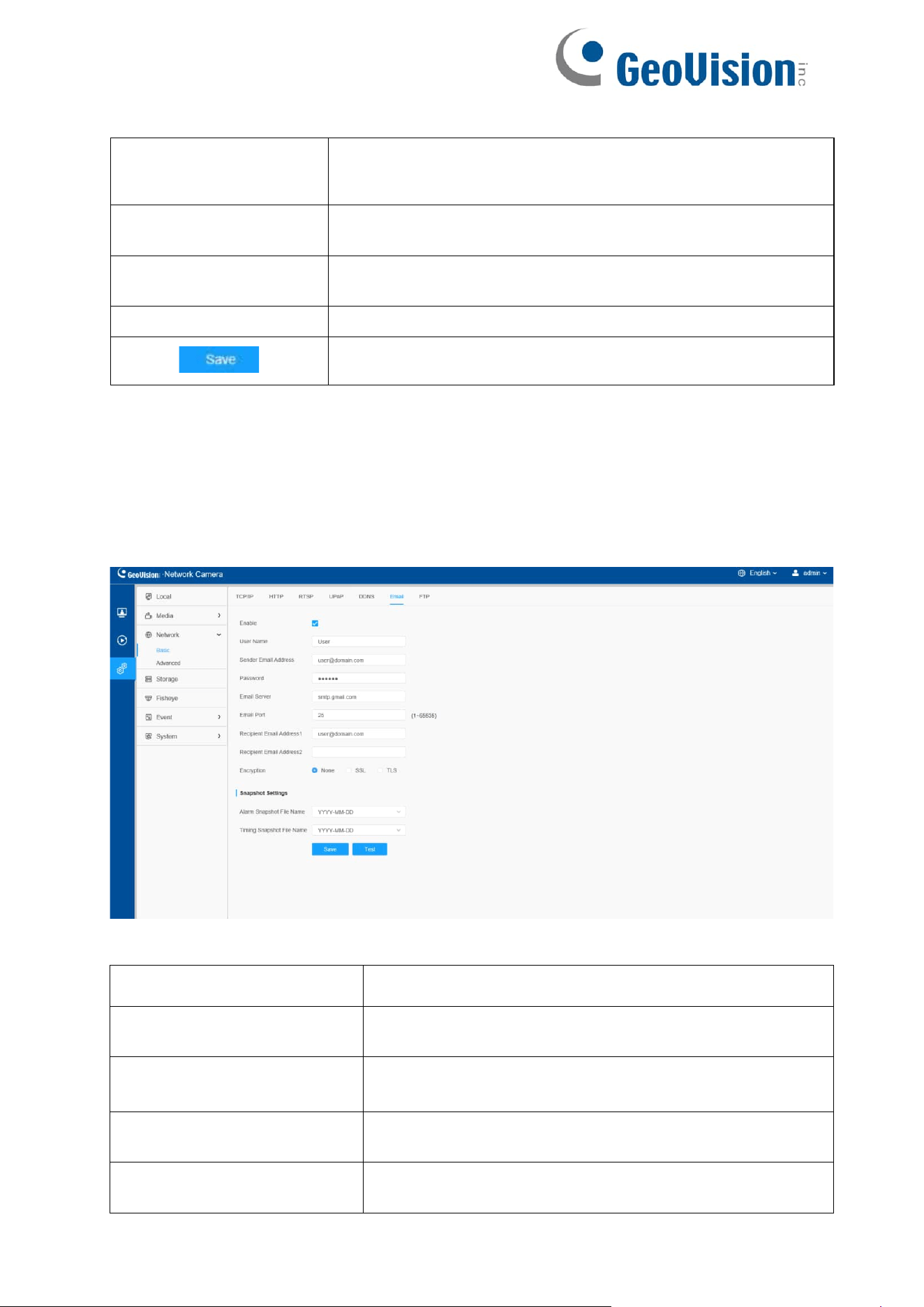
8.2.1.6 Email
Alarm video files can be sent to specific mail account through SMTP server. You must
configure the email settings correctly before using it.
Table 27. Description of the buttons
Parameters
Function Introduction
Enable
Check the checkbox to enable Email function.
User Name
The sender's name. It is usually the same as the account
name.
Sender Email Address
Email address to send video files attached emails.
Password
The password of the sender.
60
Email Server
The email server IP address or host name (e.g.,
smtp.gmail.com).
Email Port
The default TCP/IP port for SMTP is 25 (not secured).
For SSL/TLS port, it depends on the mail you use.
Recipient Email Address1
Email address to receive video files.
Recipient Email Address2
Email address to receive video files.
Encryption
Check the checkbox to enable SSL or TLS if it is
required by the SMTP server.
Snapshot Settings
Alarm Snapshot File Name: Default (YYYY-MM-DD)
/MM-DD-YYYY/ DD- MM-YYYY/ Add prefix/ Overwrite
with the base file name/ Customize are available.
Timing Snapshot File Name: Default (YYYY-MM-DD)
/MM-DD-YYYY/ DD- MM-YYYY/ Add prefix/ Overwrite
with the base file name/ Customize are available.
Save the configuration.
Test whether the configuration is successful.
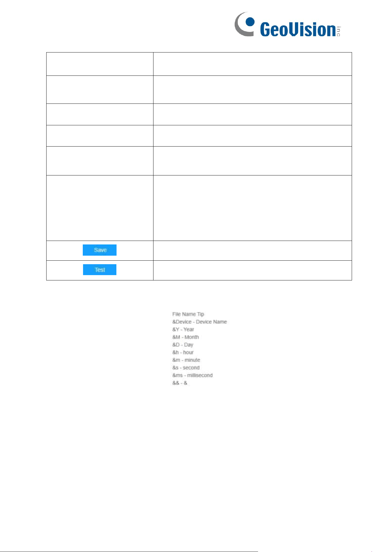
Note: You can refer to the following file name tip to customize the file name.
61
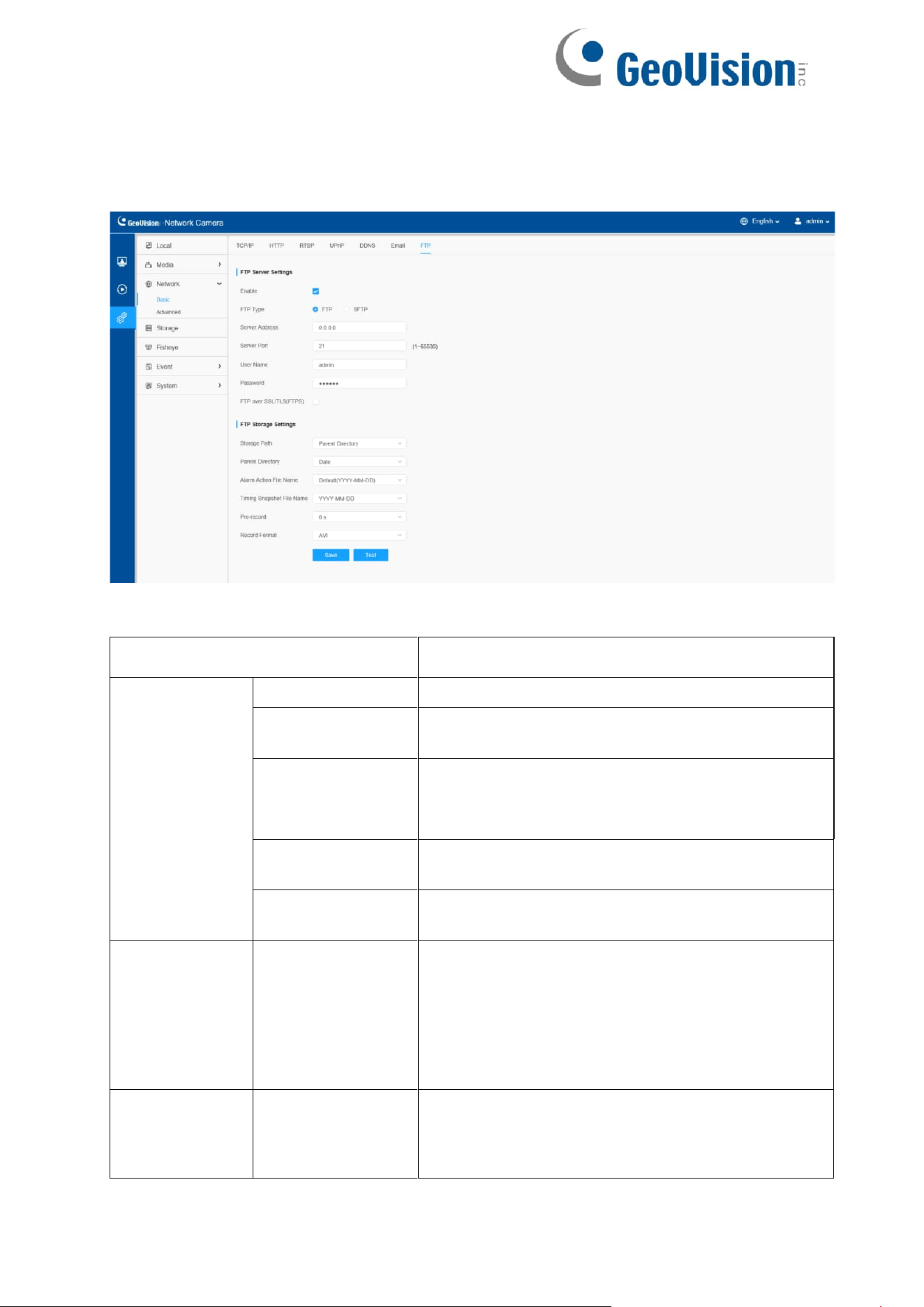
8.2.1.7 FTP
Alarm video files can be sent to specific FTP server. You must configure the FTP
settings correctly before using it.
Table 28. Description of the buttons
Parameters
Function Introduction
FTP Server
Settings
FTP Type
FTP and SFTP are optional.
Server Address
FTP/SFTP server address.
Server Port
The port of the FTP server. Generally, it is 21.
The port of the SFTP server. Generally, it is 22.
User Name
User name used to log in to the FTP/SFTP sever.
Password
User password.
FTP Storage
Settings
Storage Path
Storage Path where video and image will be
uploaded to the FTP server.
Four FTP storage path types are available,
including Root Directory,
Parent Directory, Child
Directory and Customize.
FTP Storage
Settings
Parent Directory
Choose IP Address/ Device Name/ Date as
the folder name of Parent Directory, or
customize the folder name.
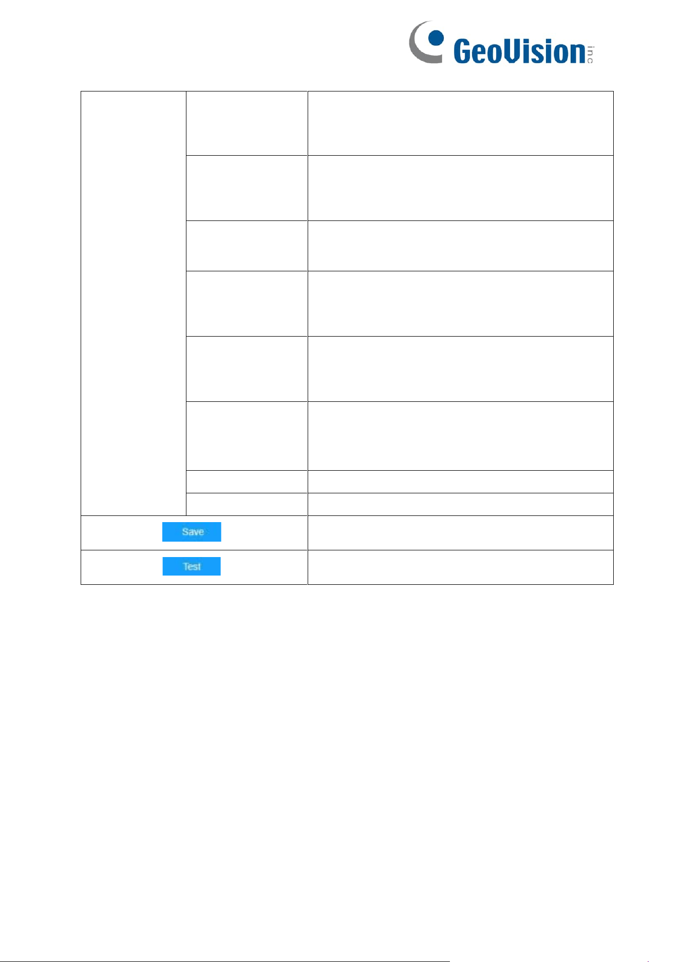
62
Child Directory
Choose IP Address/ Device Name/ Date as the
folder name of Child Directory, or customize the
folder name.
Multilevel Folder
Name
If the storage path is more than two levels,
enter Multilevel FTP storage path here
manually.
Alarm Action
File Name
Choose the default (YYYY-MM-DD) or customize
the alarm action file name.
Video File Name
If you choose to customize the alarm action file
name, YYYY-MM- DD/ MM-DD-YYYY/ DD-MM-
YYYY/ Add prefix are available.
Image File Name
If you choose to customize the alarm action file
name, YYYY-MM- DD/ MM-DD-YYYY/ DD-MM-
YYYY/ Add prefix are available.
Timing
Snapshot File
Name
Default (YYYY-MM-DD) /MM-DD-YYYY/ DD-
MM-YYYY/ Add prefix/ Overwrite with the base
file name are available.
Pre Second
Reserve the record time before alarm, 0~10 sec.
Record Format
Choose AVI / MP4 as the default record file format.
Save the configuration, 0s ~ 10s are optional.
Test whether the configuration is successful.
Note: Parent Directory will be under Root Directory, and Child Directory will be under
Parent Directory.
63
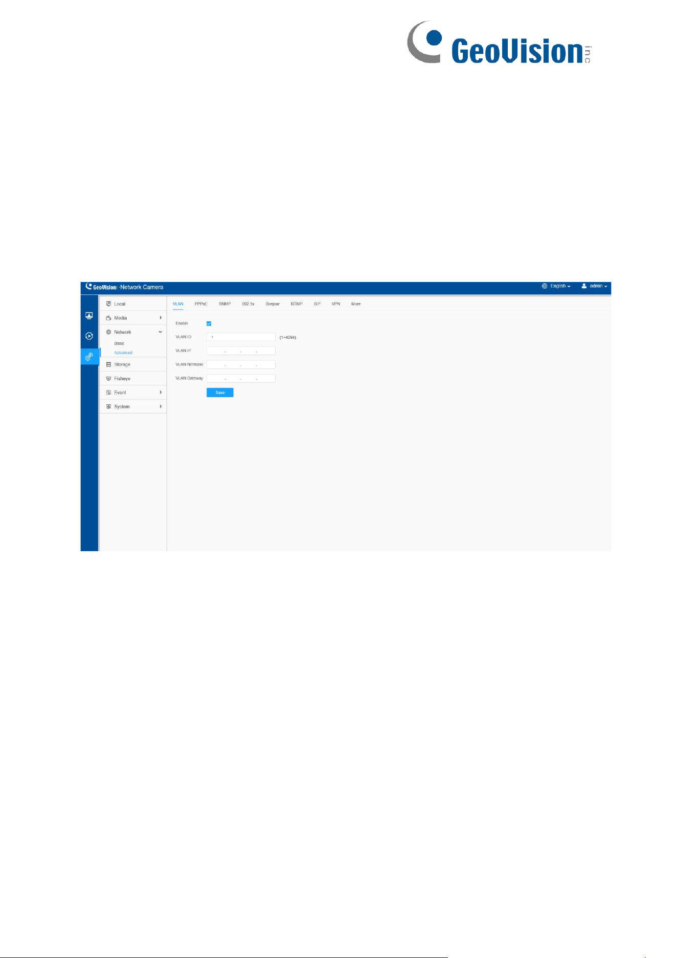
8.2.2 Advanced
8.2.2.1 VLAN
A virtual LAN (VLAN) is any broadcast domain that is partitioned and isolated in a
computer network at the data link layer (OSI layer 2). LAN is an abbreviation of local
area network. VLANs allow network administrators to group hosts together even if the
hosts are not on the same network switch. This can greatly simplify network design
and deployment, because VLAN membership can be configured through software.
Without VLANs, grouping hosts according to their resource needs necessitates the
labor of relocating nodes or rewiring data links.
Note: About how to set up VLAN in switches, please refer to your switch user manual.
64
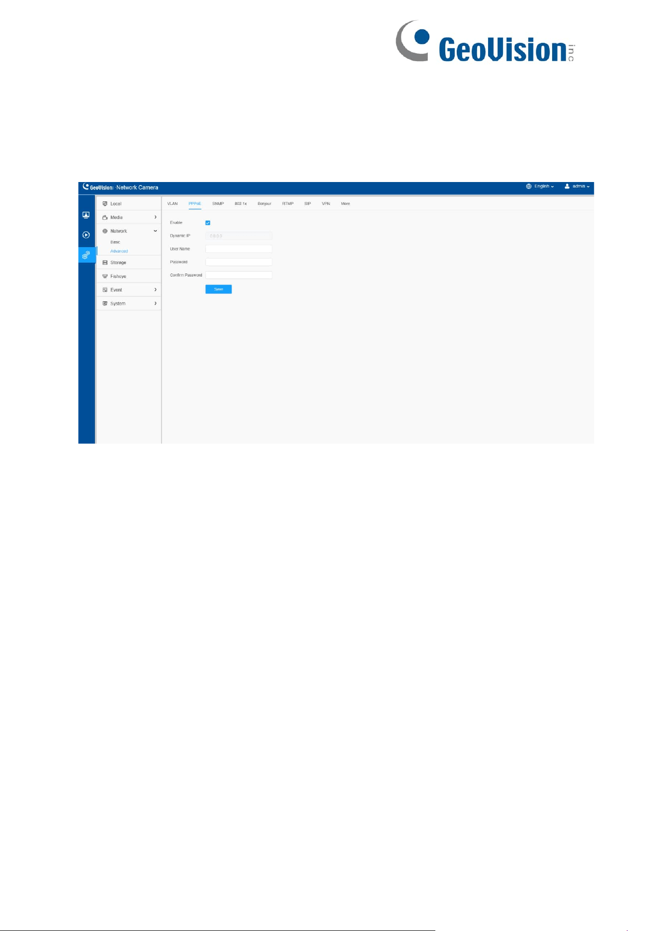
8.2.2.2 PPPoE
This camera supports the PPPoE auto dial-up function. The camera gets a public IP
address by ADSL dial-up after the camera is connected to a modem. You need to
configure the PPPoE parameters of the network camera.
Note:
The obtained IP address is dynamically assigned via PPPoE, so the IP
address always changes after rebooting the camera. To solve the
inconvenience of the dynamic IP, you need to get a domain name from the
DDNS provider (e.g., DynDns.com).
The user name and password should be assigned by your ISP.
65
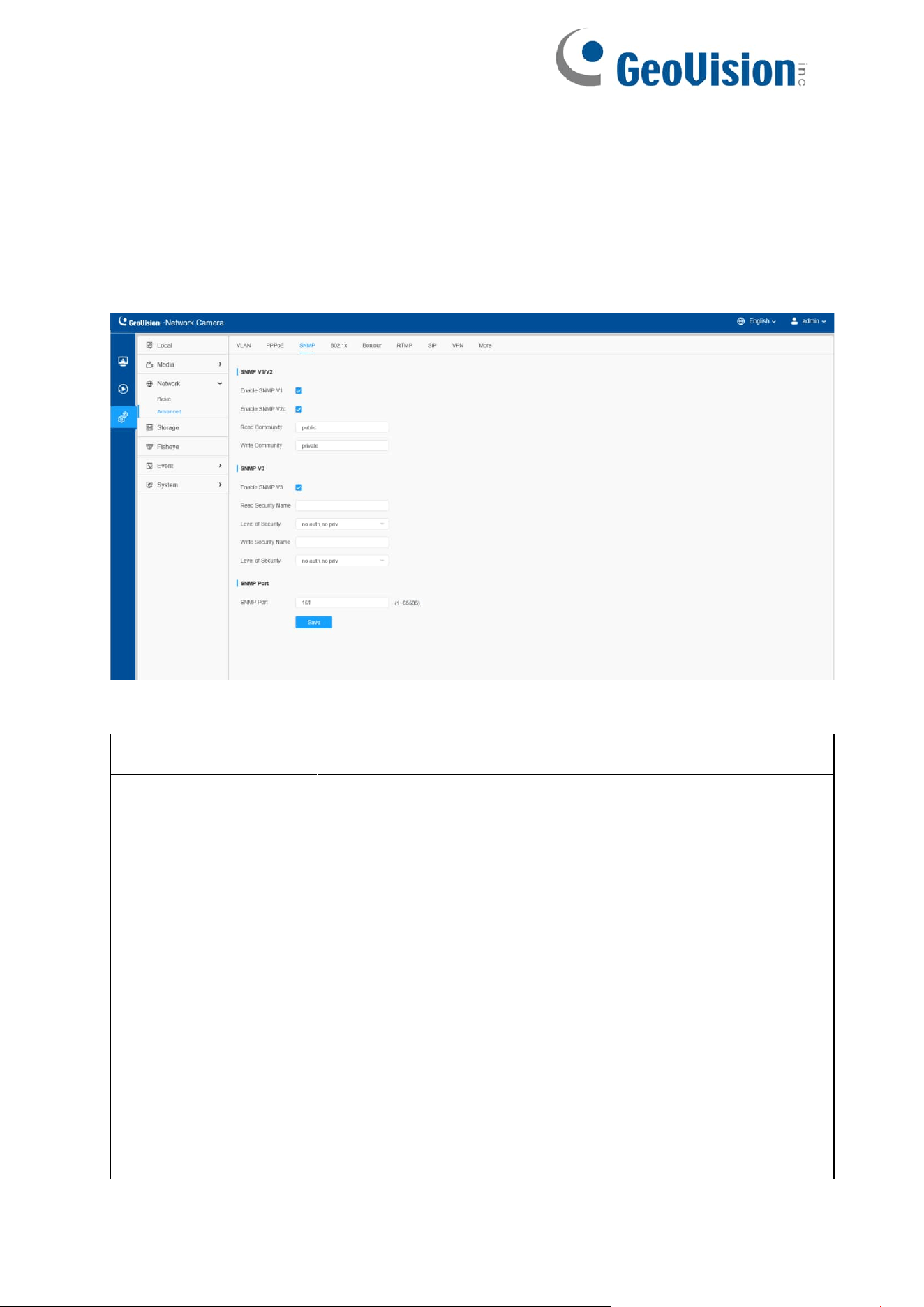
8.2.2.3 SNMP
You can set the SNMP function to get camera status, parameters and alarm related
information and manage the camera remotely when it is connected to the network.
Before setting the SNMP, please download the SNMP software and manage to
receive the camera information via SNMP port. By setting the Trap Address, the
camera can send the alarm event and exception messages to the surveillance center.
Table 29. Description of the buttons
Parameters
Function Introduction
SNMP v1/v2
The version of SNMP, please select the version of
your SNMP software.
Enable SNMP v1: Provide no security.
Enable SNMP v2: Require password for access.
Write Community: Input the name of Write Community.
Read Community: Input the name of Read Community
SNMP v3
Enable SNMP v3: Provide encryption and the HTTPS protocol
must be enabled.
Read Security Name: Input the name of Read Security
Community.
Level of Security: There are three levels available: (auth,
priv), (auth, no priv) and (no auth, no priv).
Write Security Name: Input the name of Write Security
Community.
Level of Security: There are three levels available: (auth,
priv), (auth, no priv) and (no auth, no priv).
66
SNMP Port
The port of SNMP, the default is 161.
Save the configuration.
Note:
The settings of SNMP software should be the same as the settings you configure
here;
A reboot is required for the settings to take effect.
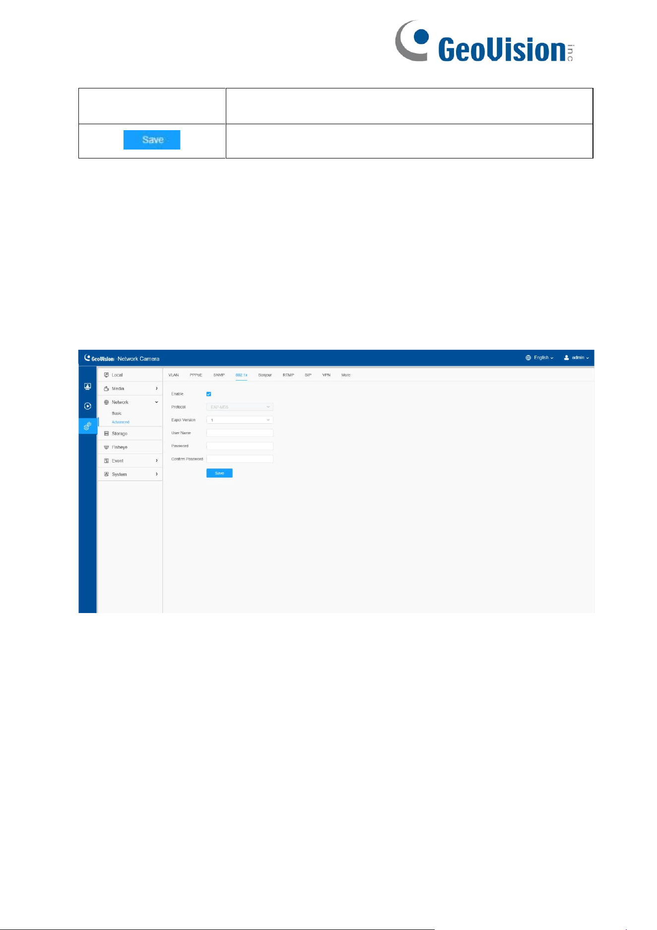
8.2.2.4 802. 1x
The IEEE 802. 1X standard is supported by the network cameras, and when the feature
is enabled, the camera data is secured and user authentication is needed when
connecting the camera to the network protected by the IEEE 802. 1X.
67
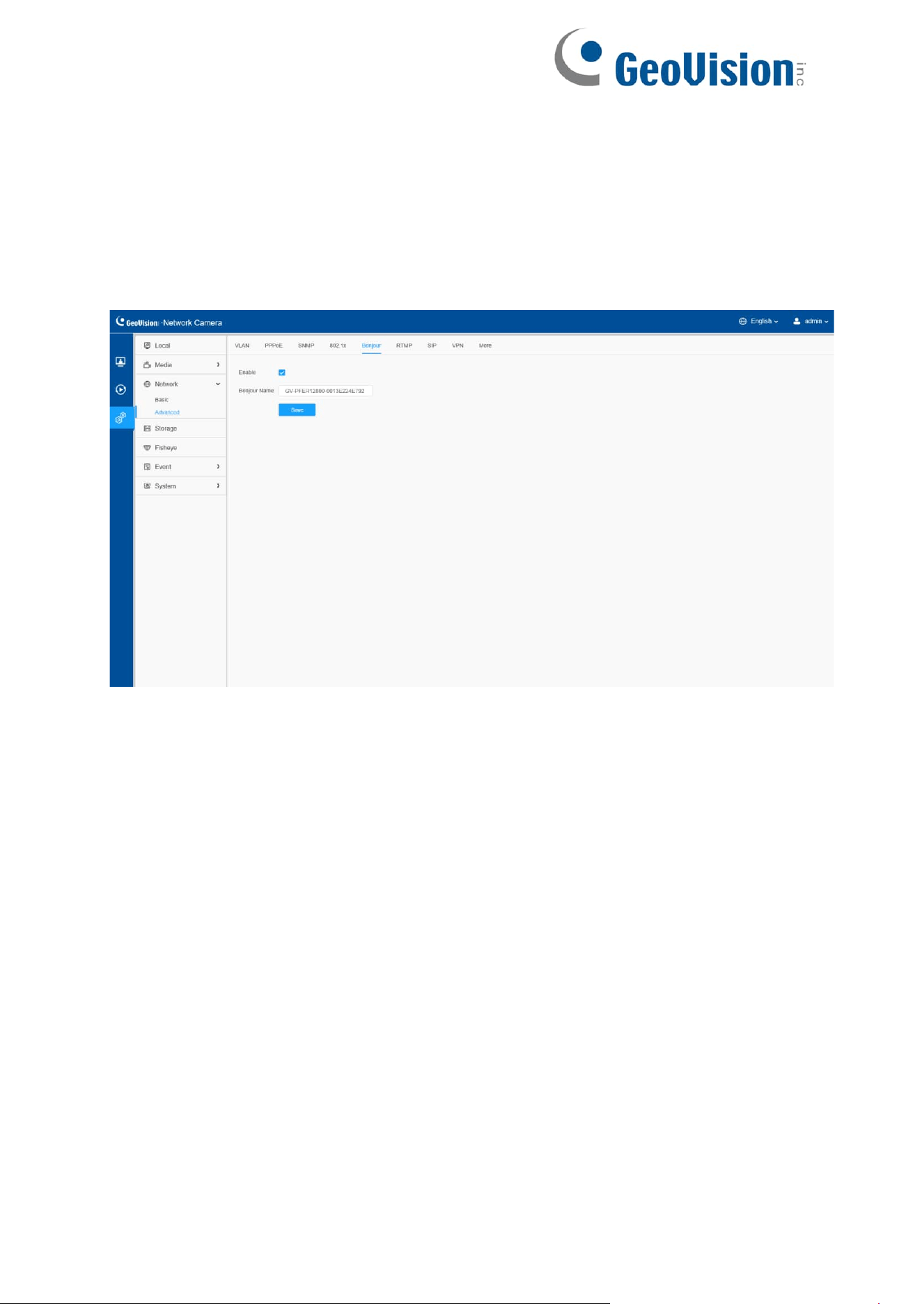
8.2.2.5 Bonjour
Bonjour is based on Apple's multicast DNS service. Bonjour devices can
automatically broadcast their service information and listen to the service information
of other devices.
If you don't know the camera information, you can use the Bonjour service on the
same LAN to search for network camera devices and then to access the devices.
68
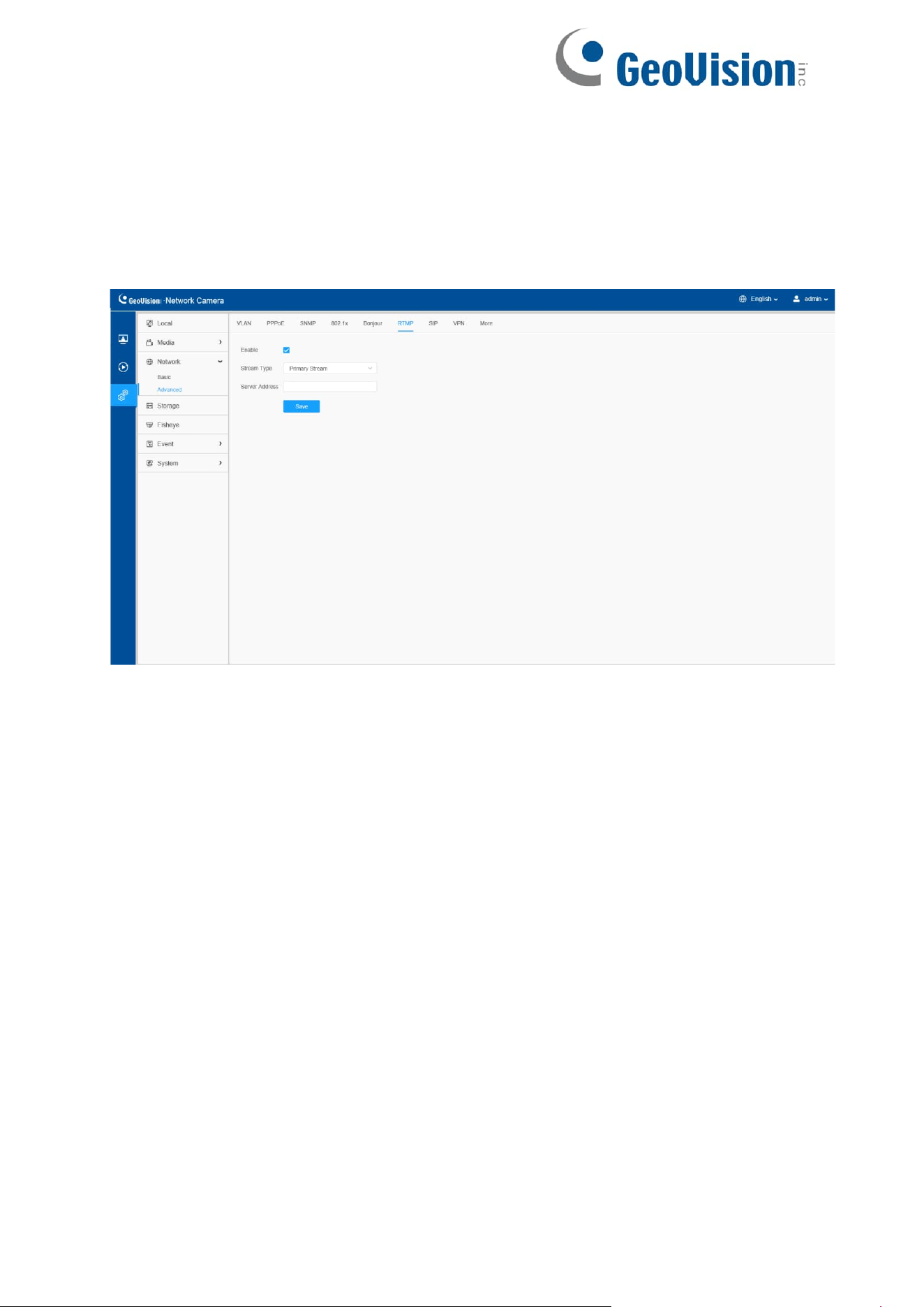
8.2.2.6 RTMP
Real-Time Messaging Protocol (RTMP) was initially a proprietary protocol for streaming
audio, video and data over the Internet, between a Flash player and a server. RTMP is a
TCP-based protocol which maintains persistent connections and allows low-latency
communication. It can realize the function of live broadcast so that customers can log in
to the camera wherever there is a network.
Note:
Server Address in Network Camera RTMP interface needs to be filled with
the format: rtmp://< Server URL >/< Stream key >. Remember it needs ’/’to
connect between < Server URL > and < Stream key >.

69
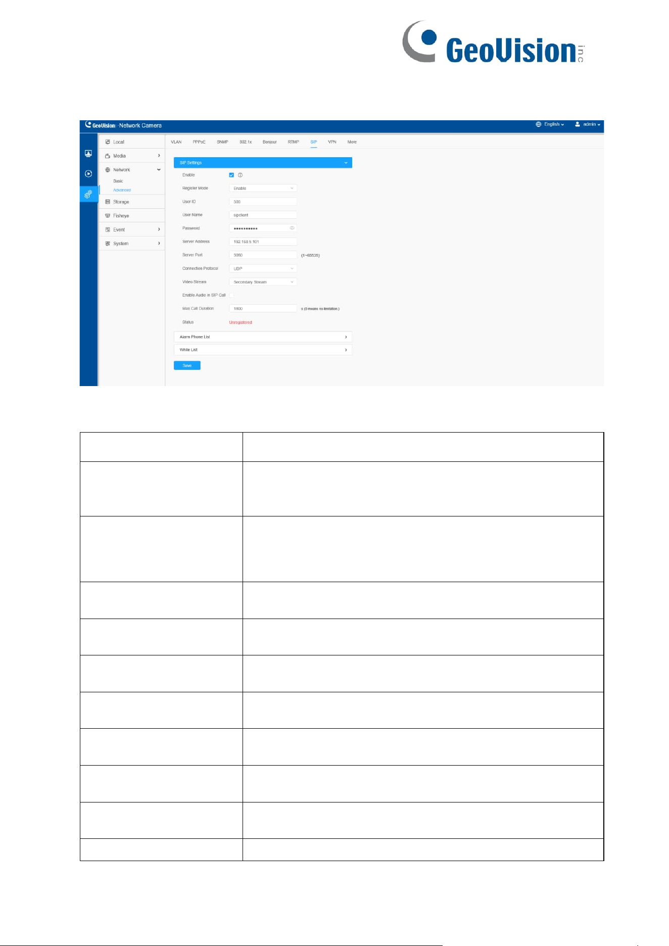
8.2.2.7 SIP
The Session Initiation Protocol (SIP) is a signaling communications protocol, widely
used for controlling multimedia communication sessions such as voice and video calls
over Internet Protocol (IP) networks. This page allows user to configure SIP related
parameters. The camera can be configured as SIP endpoint to call out when alarm
triggered; or allow permitted number to call in to check the video if the video IP phone
is used.
To use this function, the settings in SIP page must be configured properly. There are
two ways to get video through SIP, one is to dial the IP address directly, the other is
account registration mode. The details are as follows:
Method 1: IP Direct mode
Dial on the camera’s IP address directly through SIP phone, so you can
see the video.
Note: SIP phone and the camera should in the same network segment.
Method 2: Account registration mode
•
Before using the SIP, you need to register an account for the camera from the
SIP server;
•
Register another user account for the SIP device from the same SIP server;
•
Call the camera User ID from the SIP device, you will get the video on the SIP
device.
70
[SIP Settings]
Table 30. Description of the buttons
Parameters
Function Introduction
Enable
Start or stop using SIP.
Note: SIP supports Direct IP call.
Register Mode
Choose to use Enable mode or Disable mode. Enable
mode means to use SIP with register account. Disable
mode refers to use SIP without register account, just use
the IP address to call.
User ID
SIP ID.
User Name
SIP account name.
Password
SIP account password.
Server Address
Server IP address.
Server Port
Server port.
Connection Protocol
UDP/TCP.
Video Stream
Choose the video stream.
Enable Audio in SIP Call
Enable/disable audio in SIP call.
71
Max Call Duration
The max call duration when use SIP.
Status
SIP registration status. Display “Unregistered” or
“Registered”.
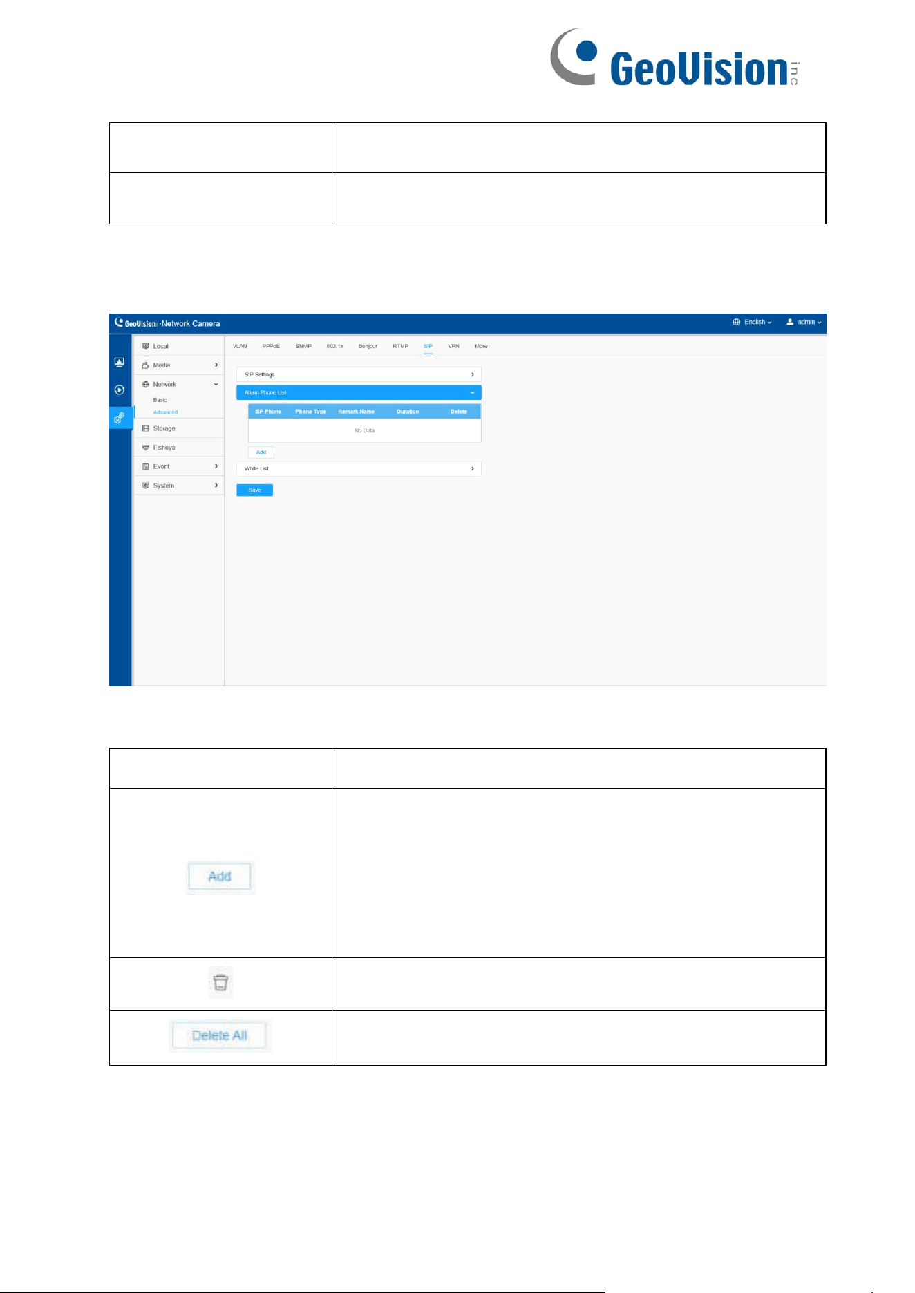
[Alarm Phone List]
Table 31. Description of the buttons
Parameters
Function Introduction
Add alarm phone to the camera.
Phone Type: Phone Number (Call by phone number) &
Direct IP Call (Check to accept peer to peer IP call).
To Phone Number/IP Address: Call by phone
number or IP address.
Remark Name: Display name.
Duration: The time schedule to use SIP.
Delete the selected alarm phone.
Delete all added alarm phone.
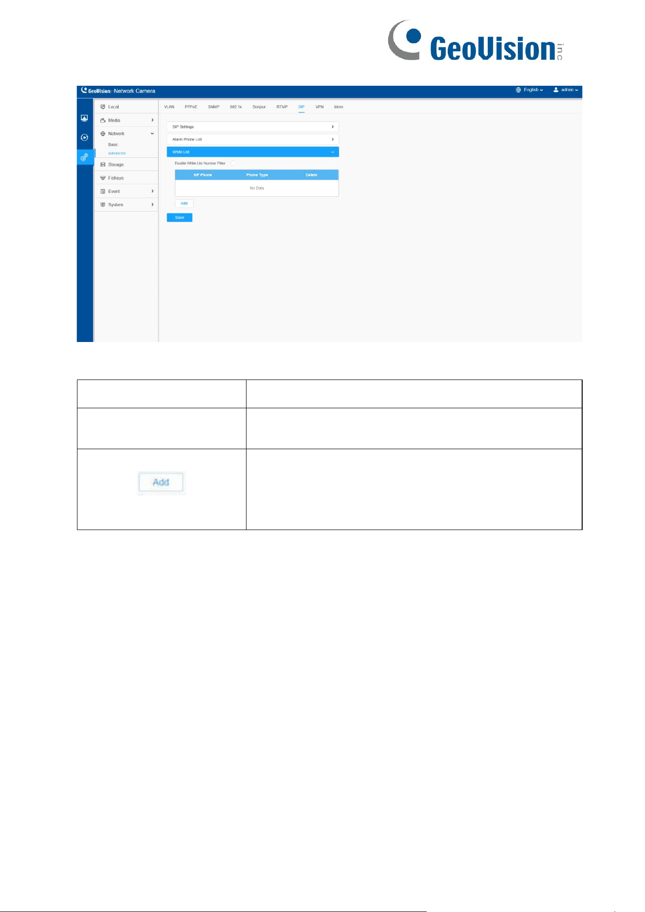
[White List]
72
Table 32. Description of the buttons
Parameters
Function Introduction
Enable White List
Number Filter
When enabled, only the designated phone number or IP
address can visit
Phone Type: Phone Number (Call by phone number) &
Direct IP Call.
Phone Number/IP Address: Including the phone number
or IP address on the white list.

73
8.2.2.8 VPN
VPN stands for Virtual Private Network. It is a network protocol that can provide you
secure encrypted connection over the public Internet. It is s significant technology in
surveillance industry. Imagine that you have a network camera connected via public
IP address, it’s possible for others to log in or listen illegally if someone knows the
specific IP address and and forwarded port. Via VPN the camera streams and data
will be transferred through an encrypted tunnel. This encrypted VPN tunnel makes it
appear as though you are directly connected to the private network, keeping your
online activity (including your browsing history) hidden. VPN feature allows users to
log in the camera via a virtual IP, which makes it easier to configure the camera
remotely.
General VPN mode allows users to upload OpenVPN configuration file directly.
Please note that the General VPN mode is working under OpenVPN protocol. You
can take the camera as an OpenVPN client.
Exporting an OpenVPN configuration file
First we need to prepare an OpenVPN configuration file. Configuration file (also
known as connection profile) is an .ovpn text file that contains the directives,
parameters, and certificates required to establish the server-client connection. Refer
to the official instruction regarding the configuration file exporting:
https://openvpn.net/vpn-server-resources/create-connection-profiles-and-connect-
client-installers/
74
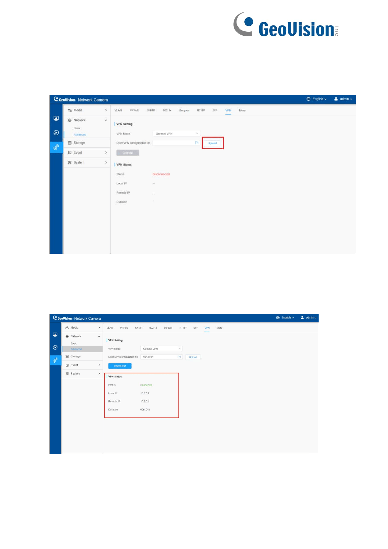
Uploading the OpenVPN configuration file
Next, we need to upload the configuration file. The connection will start automatically
once the uploading is done:
Note: If you disconnect the VPN manually or the connection is broken due to
network error, to restore connection you need to upload the configuration file on this
page again.
Check the connection status. The picture below shows a normal connection status:
75
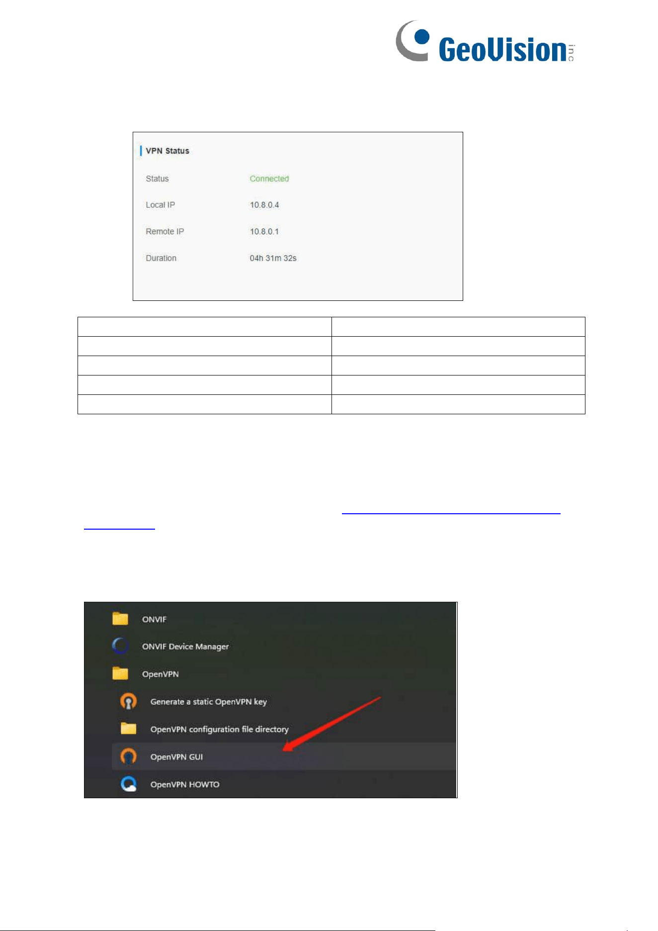
Connecting camera via VPN on the web browser
After the VPN connection is established, we can log in the camera via virtual IP
address.
Parameters
Definition
Status
Status of VPN connection
Local IP
Camera virtual IP
Remote IP
VPN virtual IP
Duration
Connection duration
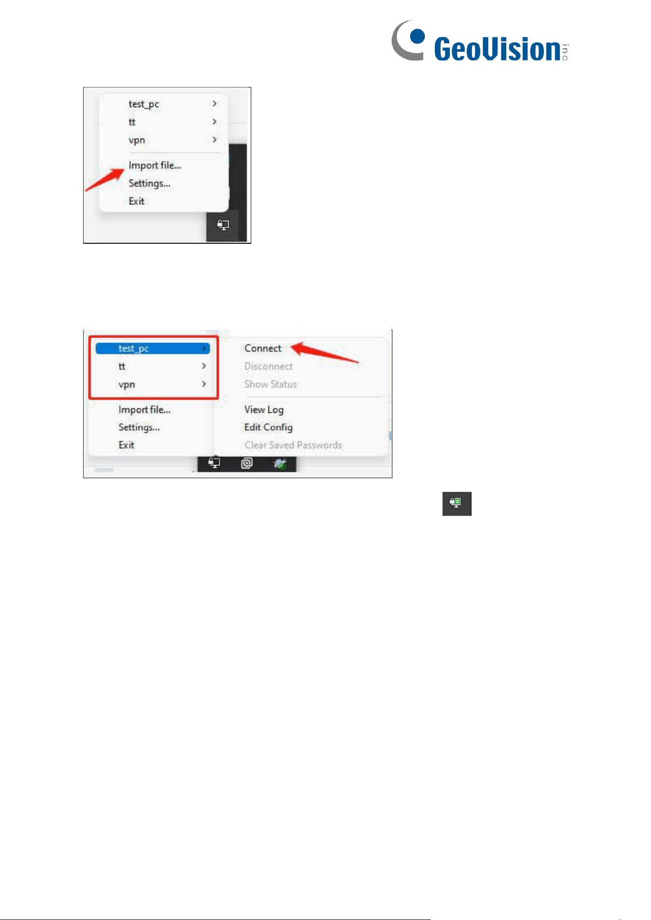
Connecting camera via VPN on OpenVPN application
Optionally, you can also connect the camera via VPN on OpenVPN application. First
please make sure your computer is also connected to VPN. For example, you can
download OpenVPN client for Windows from: https://openvpn.net/client-connect-vpn-
for-windows/
After installation, you can see the application in Start menu. Open the app
Right click the VPN connection icon on tool bar and select Import file. Please
prepare another OpenVPN configuration file that is different from camera’s.
76
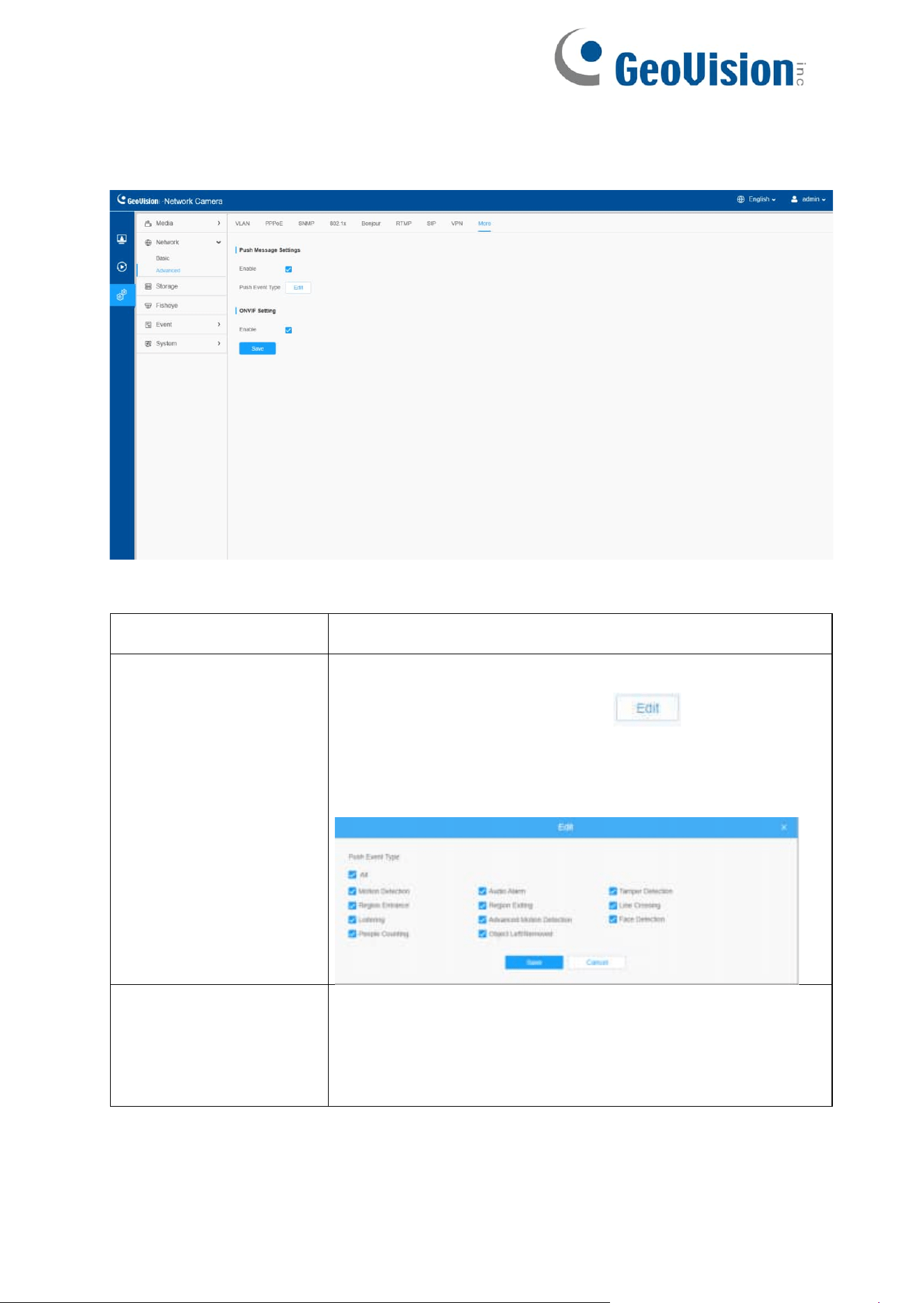
In this area, you can see all the configuration file you’ve uploaded. Select the
corresponding file to connect:
When the connection is done, your computer will show this icon: Open the
Web browser and enter virtual IP address to log in the camera via Web.
77
8.2.2.9 More
Here you can set more functions, like Push Message Settings and ONVIF Settings.
Table 33. Description of the buttons
Parameters
Function Introduction
Push Message
Settings
Enable: Enable/disable the Push Message function
Push Event Type: You can click to choose the
types of Events'
message which will be pushed to M-sight Pro App as
shown below:
ONVIF Setting
Here you can choose whether to enable or disable camera
ONVIF function. If camera ONVIF function is enabled, it can
be searched out, added and connected by third-party
software through ONVIF protocols. Generally, the default
status of ONVIF function is enabled.
8.3 Storage
78
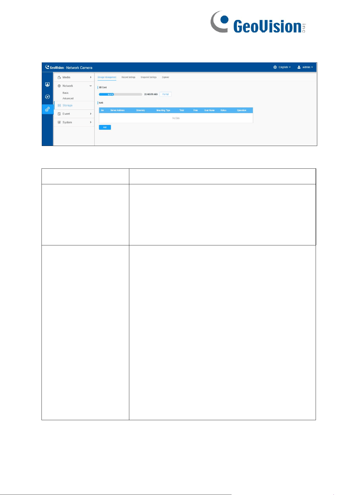
8.3.1 Storage Management
Table 34. Description of the buttons
Parameters
Function Introduction
SD Card
Format: Format SD card, the files in SD card will be
removed.
Mount/UnMount: Mount/Dismount SD card.
Delete: Enable cyclic storage, when the free disk space
reach at a certain value, it will automatically delete the
files at certain percentage according to your settings.
Nas
The network disk should be available within the
network and properly configured to store the
recorded files, etc.
NAS (Network-Attached Storage), connecting the
storage devices to the existing network, provides data
and files services.
Server Address: IP address of NAS server.
Directory: Input the NAS directory, e.g., “\path”.
Mounting Type: NFS and SMB/CIFS are available. And
you can set the user name and password to guarantee
the security if SMB/CIFS is selected.
Note:
• Up to 5 NAS disks can be connected to the camera.
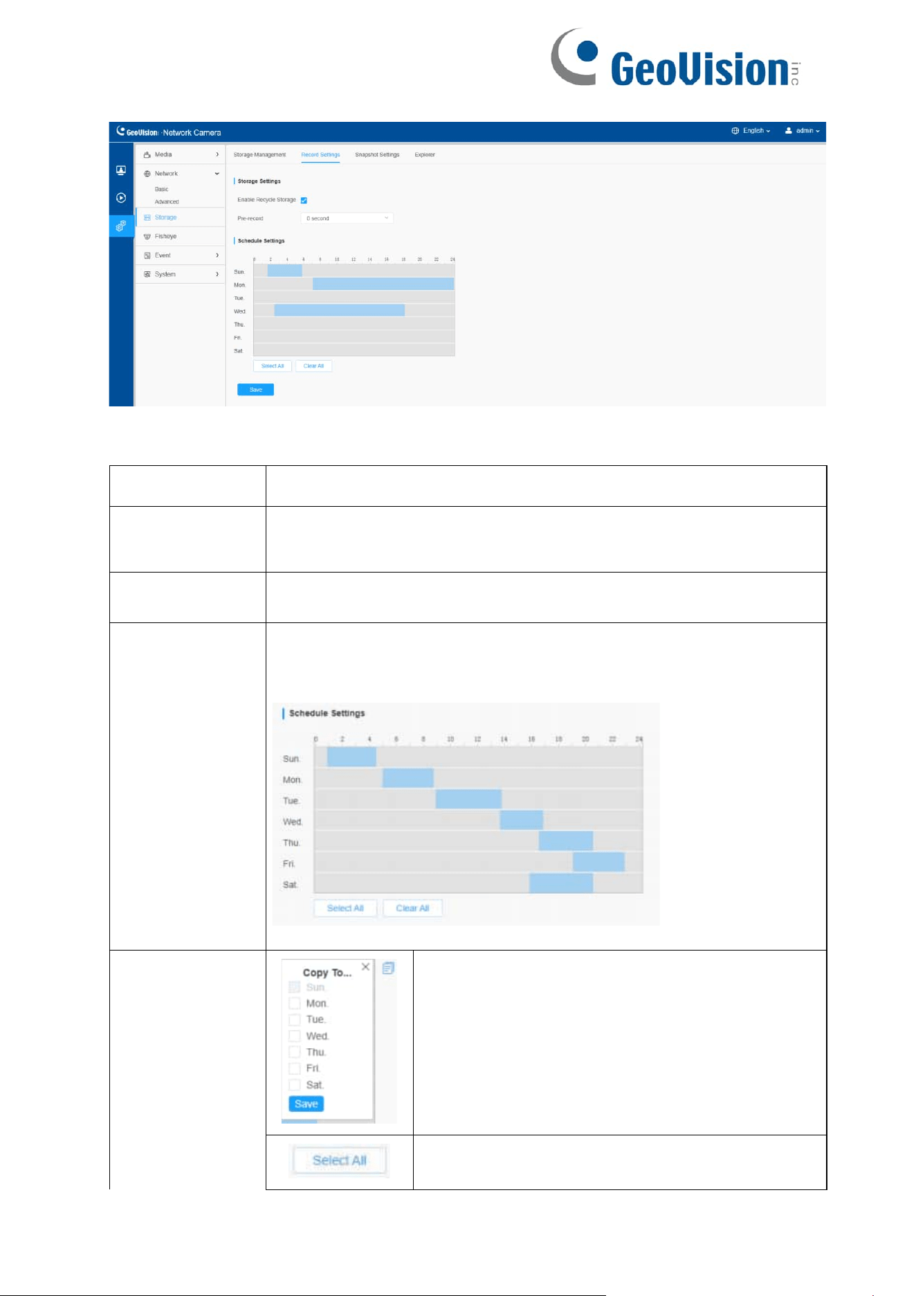
8.3.2 Record Settings
79
Table 35. Description of the buttons
Parameters
Function Introduction
Enable
Recycle
Storage
Enable/Disable Recycle Storage, if you enable this option, it will
delete the files when the free disk space reaches a certain value.
Pre Second
Reserve the record time before alarm, 0~10 sec.
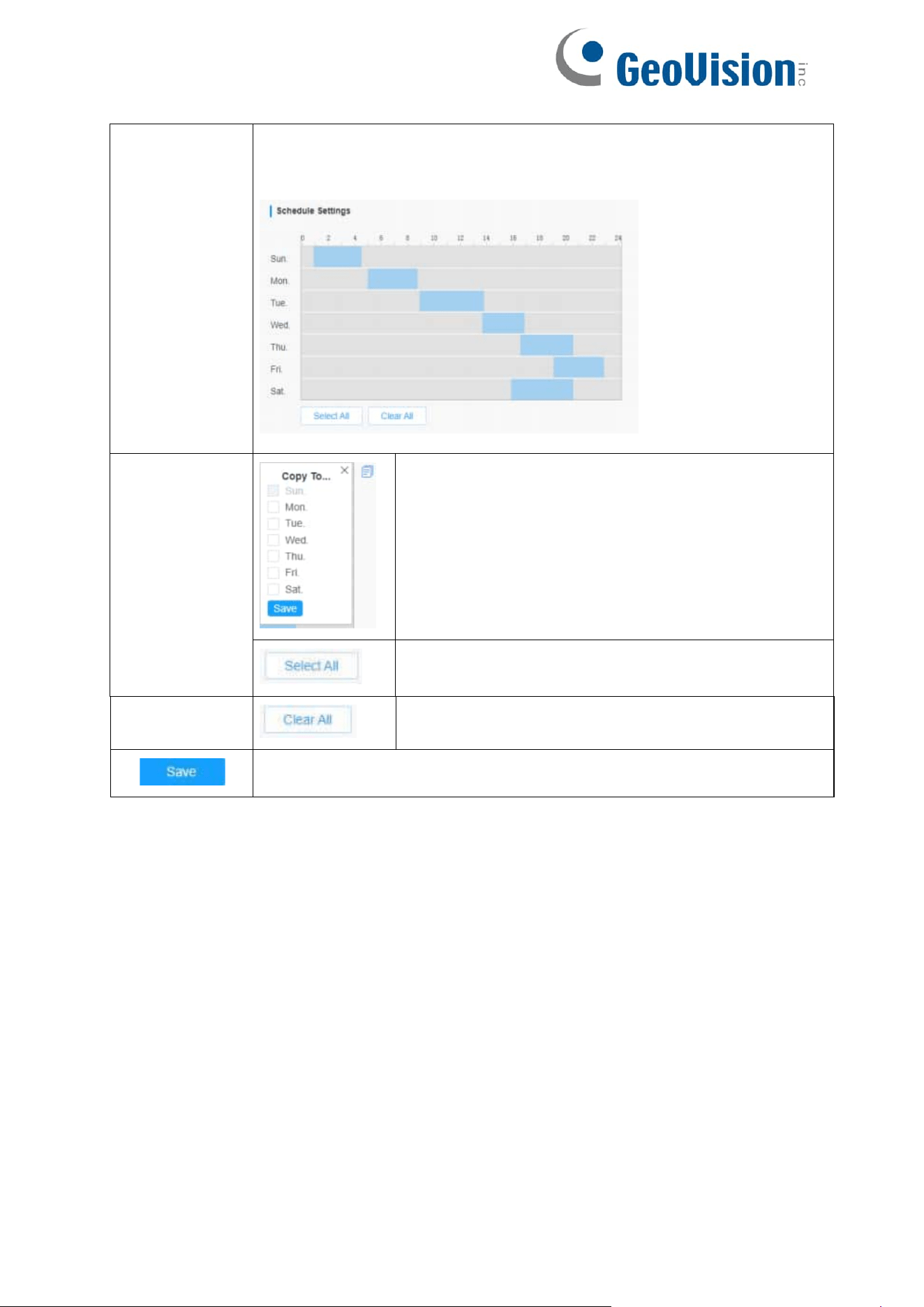
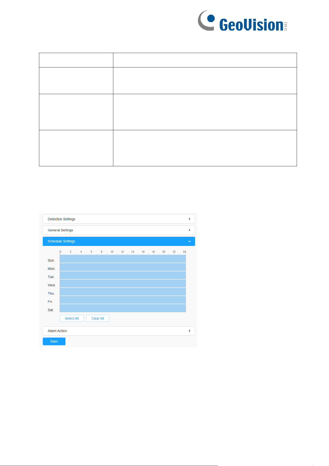
Schedule Settings
Edit record schedule as needed. Intuitive scheduling by drawing the
time bar directly.
Schedule Settings
Copy the schedule area to another date.
Select all schedule.
80
Clear all schedule.
Save the configuration.
Note: SD Card or NAS are available.
81
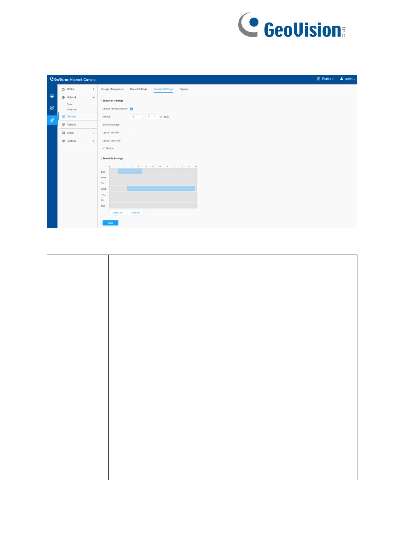
8.3.3 Snapshot Settings
Table 36. Description of the buttons
Parameters
Function Introduction
Snapshot
Settings
Enable Timing Snapshot: Check the checkbox to enable the Timing
Snapshot function
Interval: Set the snapshots interval, input the number and choose the
unit (millisecond, second, minute, hour, day).
Save Into Storage: Save the snapshots into SD card or NAS, and
choose the file name to add time suffix or overwrite the base file
name.
Save Into NAS: Save the snapshots into NAS, and choose the file
name to add time suffix or overwrite the base file name.
Upload Via FTP: Upload the snapshots via FTP.
Upload Via Email: Upload the snapshots via email.
Note: If you choose to add time suffix, every snapshot picture will be
saved, but if you choose to overwrite the base file name, only one
latest picture will be saved. When you choose add overwrite the
base file name to SD Card or NAS, it will create a file named
“ Snapshot” to place the snapshot.
HTTP Post: Upload the snapshots via HTTP Post. Support
uploading the snapshots to specified HTTP URL.
82
Schedule
Settings
Edit record schedule as needed. Intuitive scheduling by drawing the
time bar directly.
Schedule
Settings
Copy the schedule area to another date.
Select all schedule.
Clear all schedule.
Save the configuration.
83
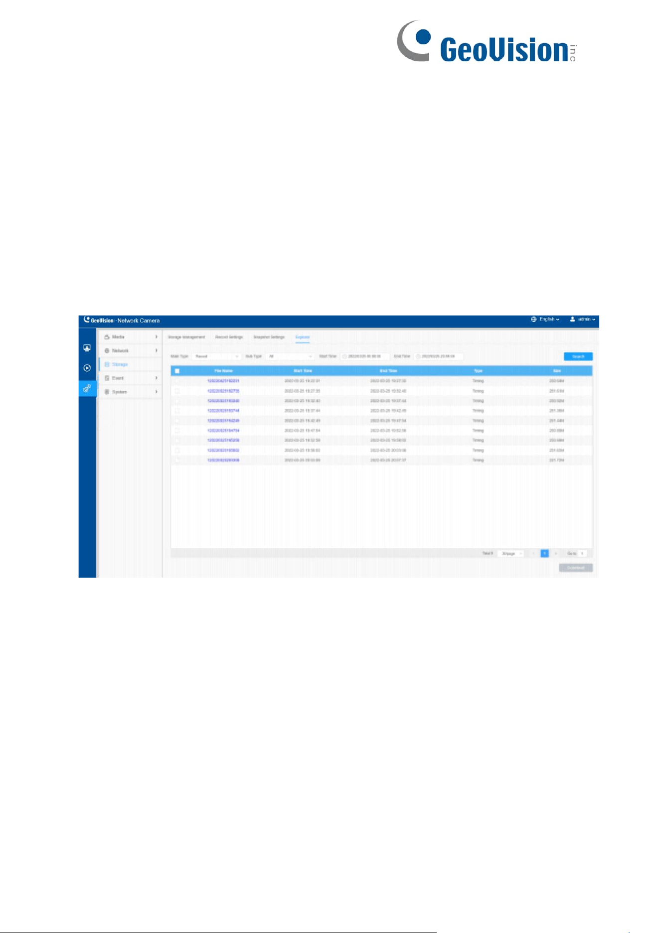
8.3.4 Explorer
Files will be seen on this page when they are configured to save into SD card or NAS.
You can set time schedule every day for recording videos and save video files to your
desired location.
Note: Files are visible once SD card is inserted. Don’t insert or pull out SD card when
power on
Video files are arranged by date. Set file type and start/end time to search out files.
Each day files will be displayed under the corresponding date, from here you can copy
and delete files etc. You can visit the files in SD card by ftp, for example,
ftp://username:password@192. 168.5. 190 (user name and password are the same as
the camera account and the IP followed is the IP of your device.).
84
8.4 Event
8.4.1 Basic Event
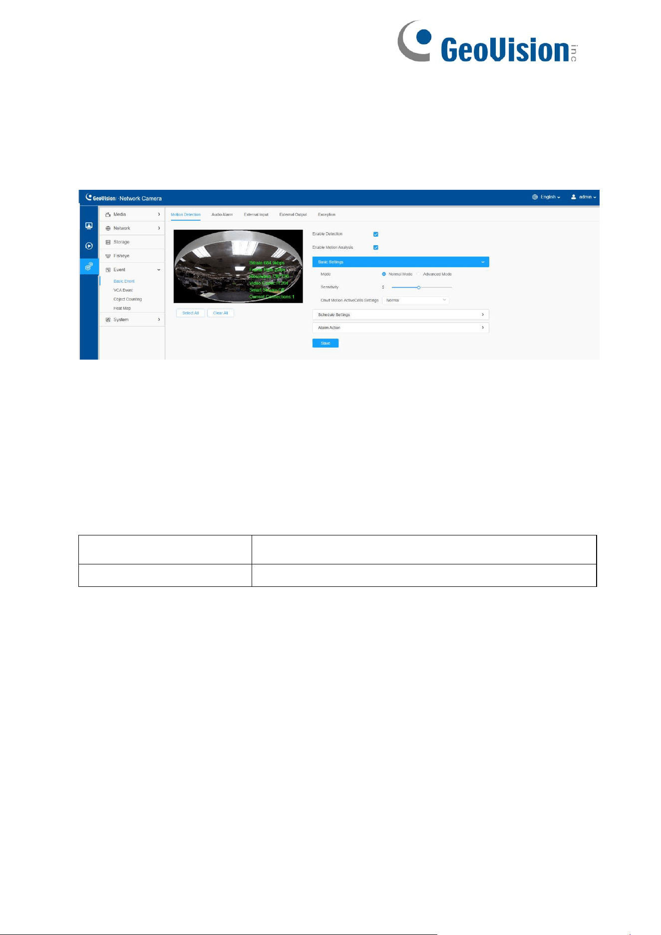
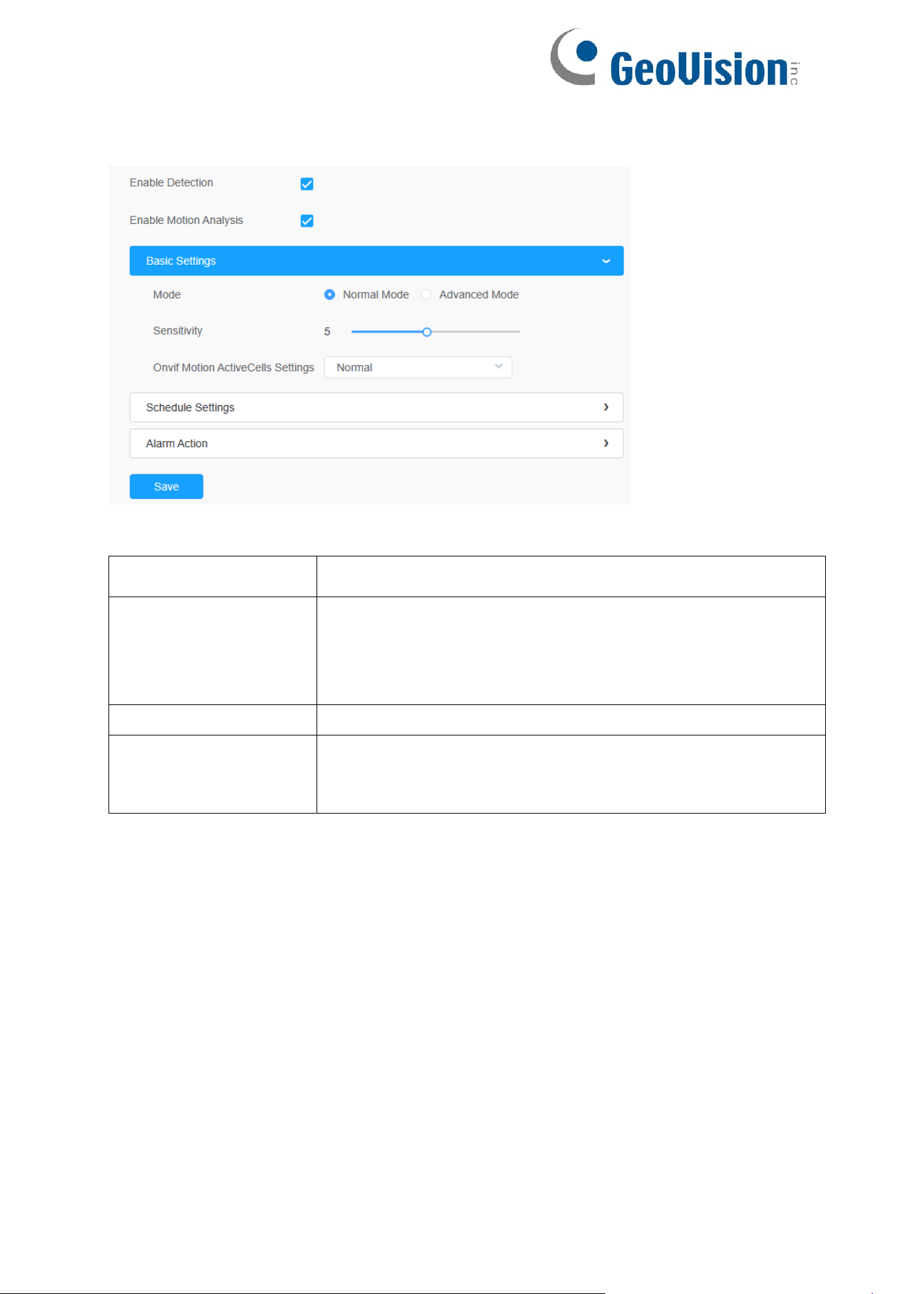
8.4.1.1 Motion Detection
Settings steps are shown as follows:
Step1: Check the checkbox to enable the motion detection.
Step2: Check the check box to enable the motion analysis.
Step3: Select the detection mode;
Step4: Set motion region;
Table 37. Description of the buttons
Parameters
Function Introduction
Enable Detection
Check the checkbox to enable Motion Detection function.
85
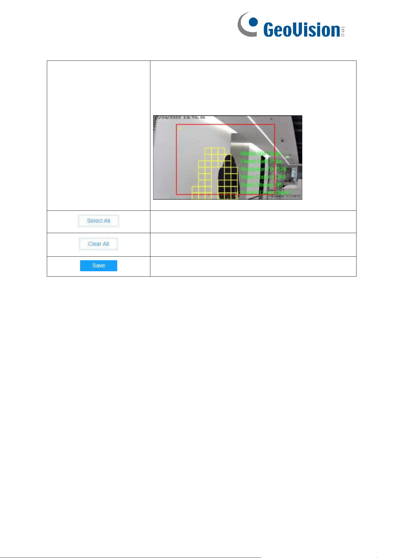
Enable Motion
Analysis
When Motion Analysis is enabled, the moving region will
turn yellow so that the user can know exactly where the
motion occurred.
Note: Only support when HTTP is selected in Live View.
Click the button, the motion in the area will be detected.
Click the button, the area drawn before will be removed.
Save the configuration.
86
[Basic Settings]
Table 38. Description of the buttons
Parameters
Function Introduction
Detection Mode
Normal Mode and Advanced Mode are available for the
option. When Advanced Mode is selected, users can
configure up to 4 detection regions and sensitivity for each
detection region.
Sensitivity
Sensitivity level, 1~10
Onvif Motion
ActiveCells
Settings
Normal and Compatible are available for the option. If the
setting of motion region of the third-party software is different
from ours, please set this option to Compatible
87
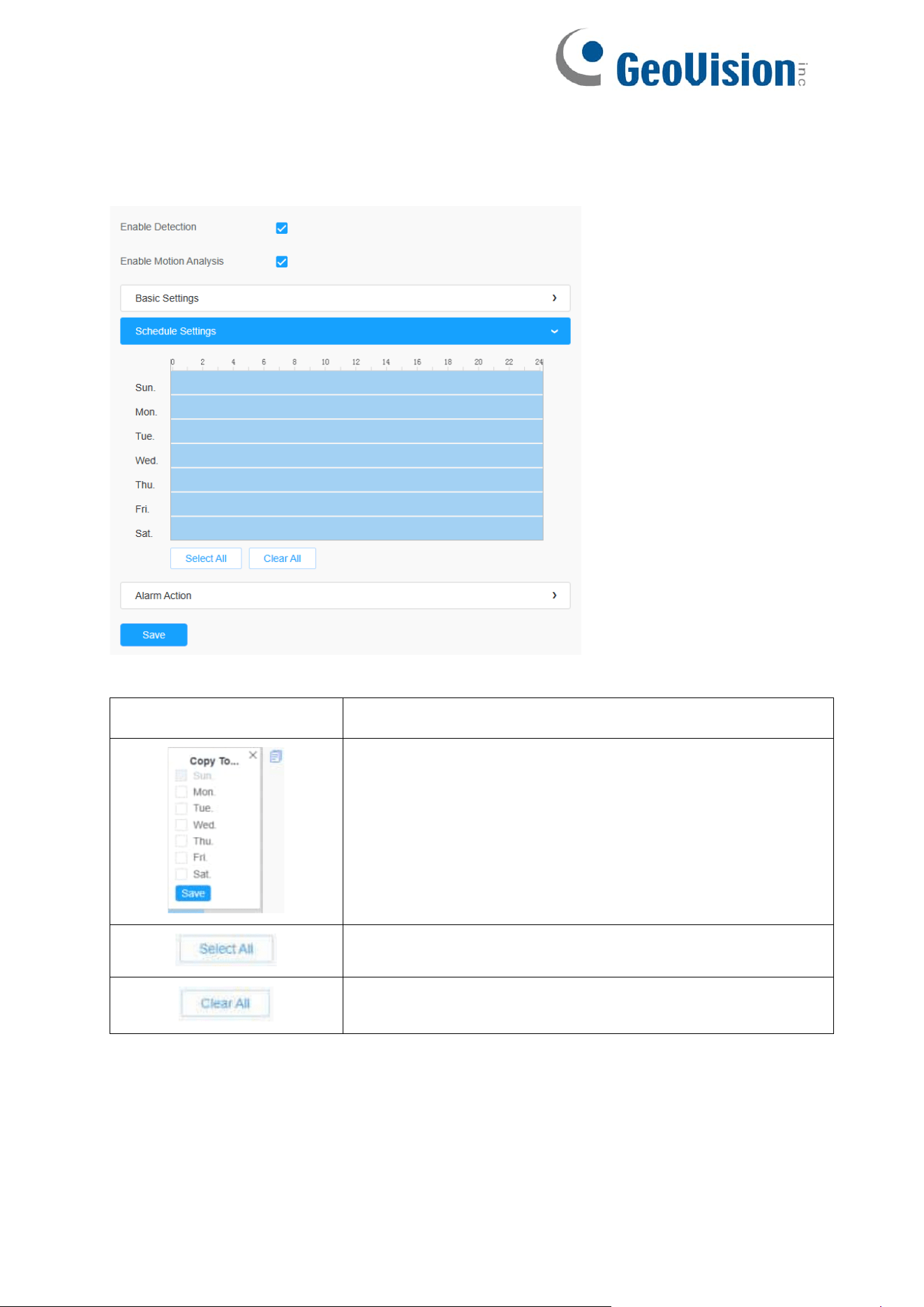
[Schedule Settings]
Step5: Set motion detection schedule;
Table 39. Description of the buttons
Parameters
Function Introduction
Copy the schedule area to another date.
Select all schedule.
Clear all schedule.
88
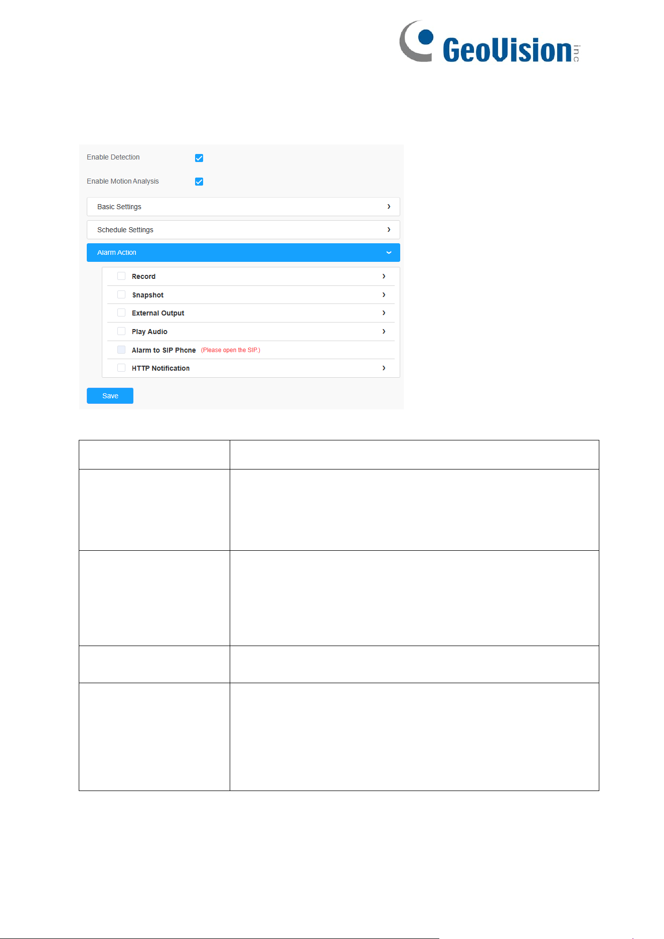
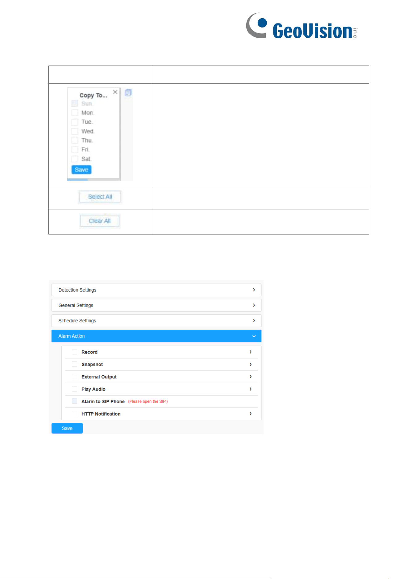
[Alarm Action]
Step6: Set alarm action;
Table 40. Description of the buttons
Parameters
Function Introduction
Record
Duration: Selected the duration time of alarm.
5s/10s/15s/20s/25s/30s are available.
Linkage: Save alarm recording files into SD Card or NAS or
Upload the recording files via FTP.
Snapshot
Number: The number of snapshots. 1~5 is available.
Interval: This cannot be edited unless you choose more than 1
to Snapshot.
Linkage: Save alarm recording files into SD Card or NAS,
Upload the recording files via FTP and send alarm email.
External Output
If the camera equips with External Output, you can
enable the action after configuring the trigger duration.
Play Audio
Auto/10 seconds/30 seconds/1 minute/5 minutes/10
minutes are available.
Note: Please enable the Audio Speaker.
89
Alarm to SIP
Phone
Support to call the SIP phone after enable the SIP function.
HTTP Notification
Support to pop up the alarm news to specified HTTP URL.
Note:
Three HTTP notifications at most can be added to the
same event.
HTTP Notification supports Basic & Digest authentication
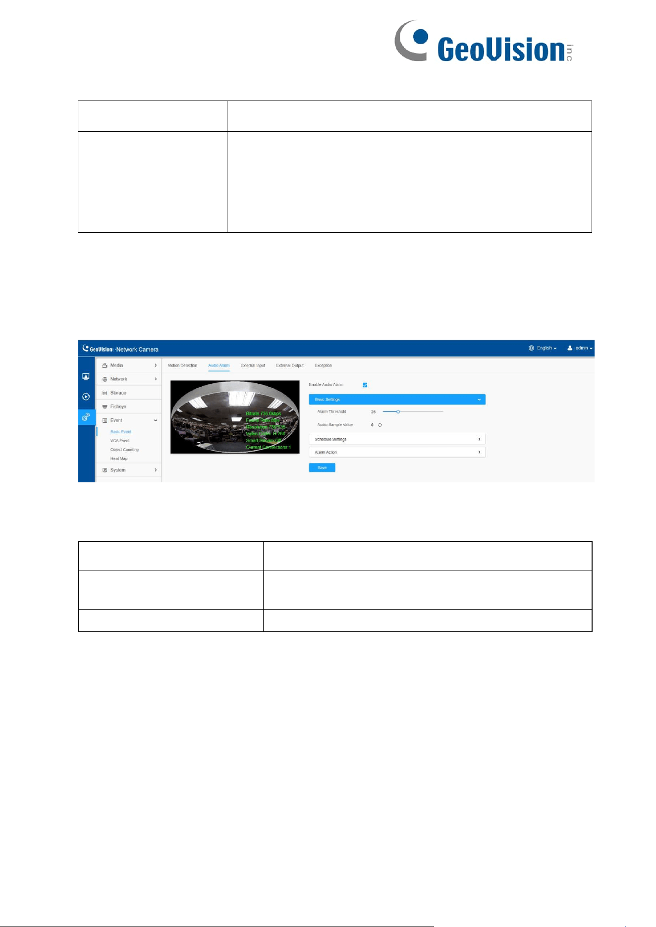
8.4.1.2 Audio Alarm
Check the check box to enable the Audio Alarm function.
Note: Enable the Audio Mic before using Audio Alarm function.
[Basic Settings]
Table 41. Description of the buttons
Parameters
Function Introduction
Alarm Threshold
Audio Alarm will be triggered when the threshold
reaches to a certain value from 0 to 100.
Audio Sample Value
The current value of the audio sample.
[Schedule Settings]
Refer to Schedule Settings in 8.4.1.1 Motion Detection for details.
[Alarm Action]
Refer to Alarm Action in 8.4.1.1 Motion Detection for details.
90
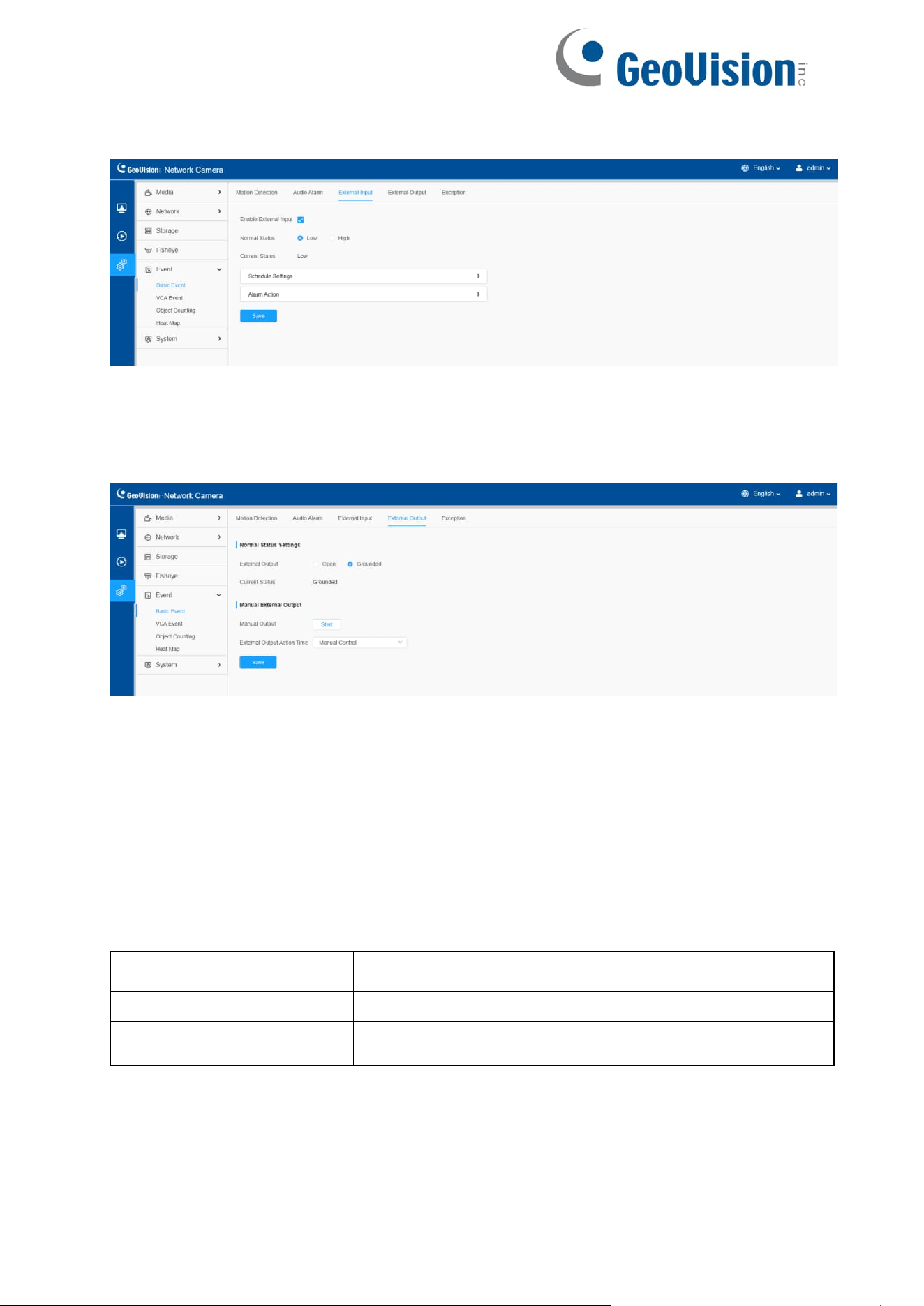
8.4.1.3 External Input
Refer to Alarm Action in 8.4.1.1 Motion Detection for details.
8.4.1.4 External Output
Please set the Normal Status firstly, when the Current Status is different with
Normal Status, it will lead to the alarm.
[Manual External Output]
You can set the manual external output.
Table 42. Description of the buttons
Parameters
Function Introduction
Manual Output
Click to Start/Stop manual external output.
External Output Action
Time
Manual Control/Customize/10 s/1 min./5 min./10 min. are
available.
91
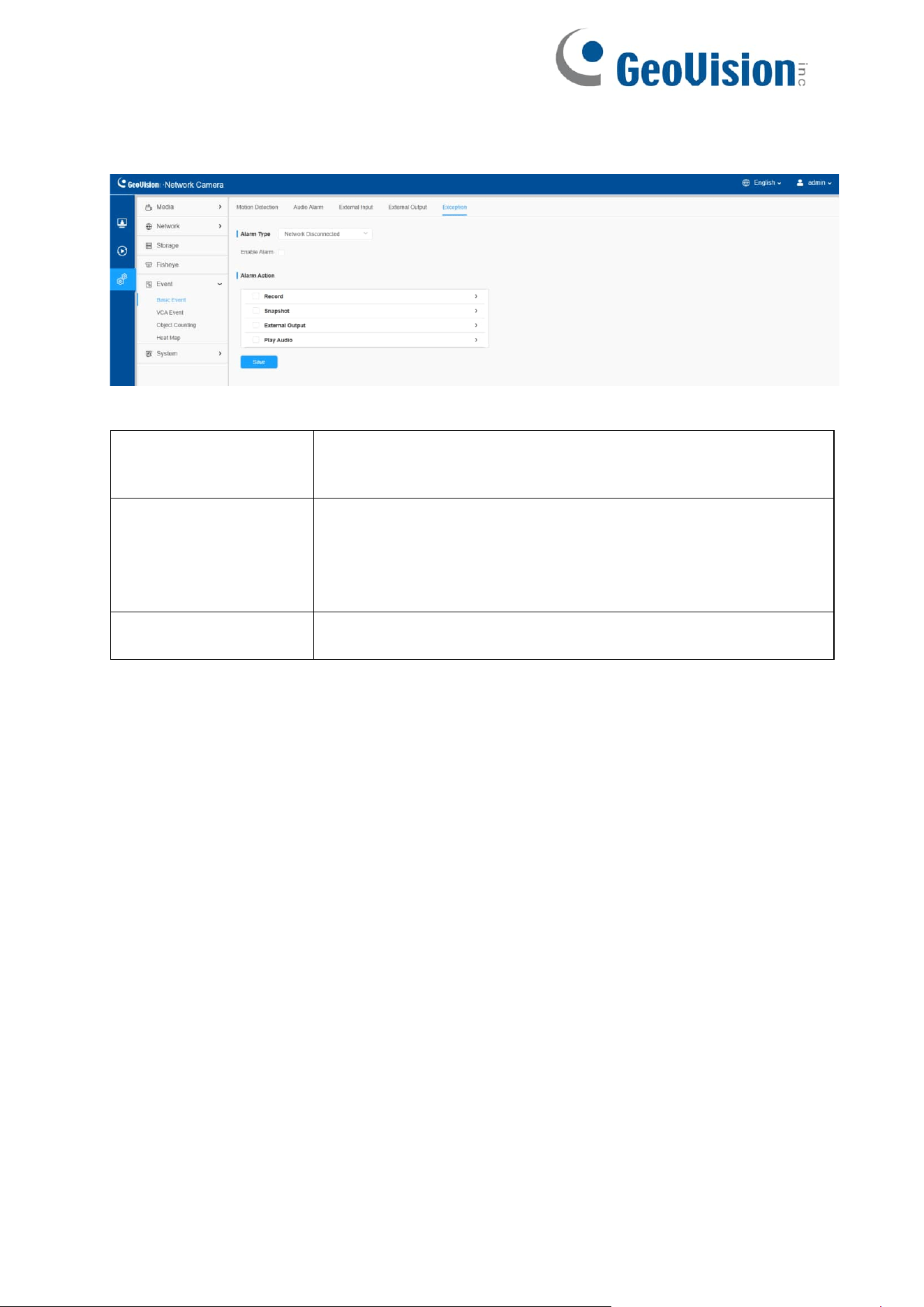
8.4.1.5 Exception
Table 43. Description of the buttons
Parameters
Function Introduction
Alarm Type
Network Disconnected, IP Address Conflicted, Record
Failed, SD Card Full, SD Card Uninitialized, SD Card Error
and No SD Card are available
Check the checkbox to enable the alarm type you selected
Alarm Action
Refer to Alarm Action in 8.4.1.1 Motion Detection for details.
92
8.4.2 VCA Event
Smart Event uses VCA (Video Content Analysis) technology, which provides advanced,
accurate smart video analysis for network cameras. Powered by AI chip, the new
generation video analytics is capable of recognizing vast attributes of human and object
pattern recognition models. As related events are very important in security monitoring,
the filtering is supported to better optimize the efficiency.
Note:
• Smart Event of fisheye camera only supports in 1O mode of Bundle-
Stream mode and 1O, 1O3R, 1O1P3R mode of Multi-Channel mode.
• Vehicle recognition is currently not applicable.
• It is suggested to install the camera at the height of 3 – 5 m for ceiling
mount and 2.5 – 4 m for wall mount.
• The applicable object size for detection is 3 x 3 – 320 x 240 pixels.
• For optimal detection results, ensure the entire object is within the screen
boundaries and does not appear partially or is cut off.
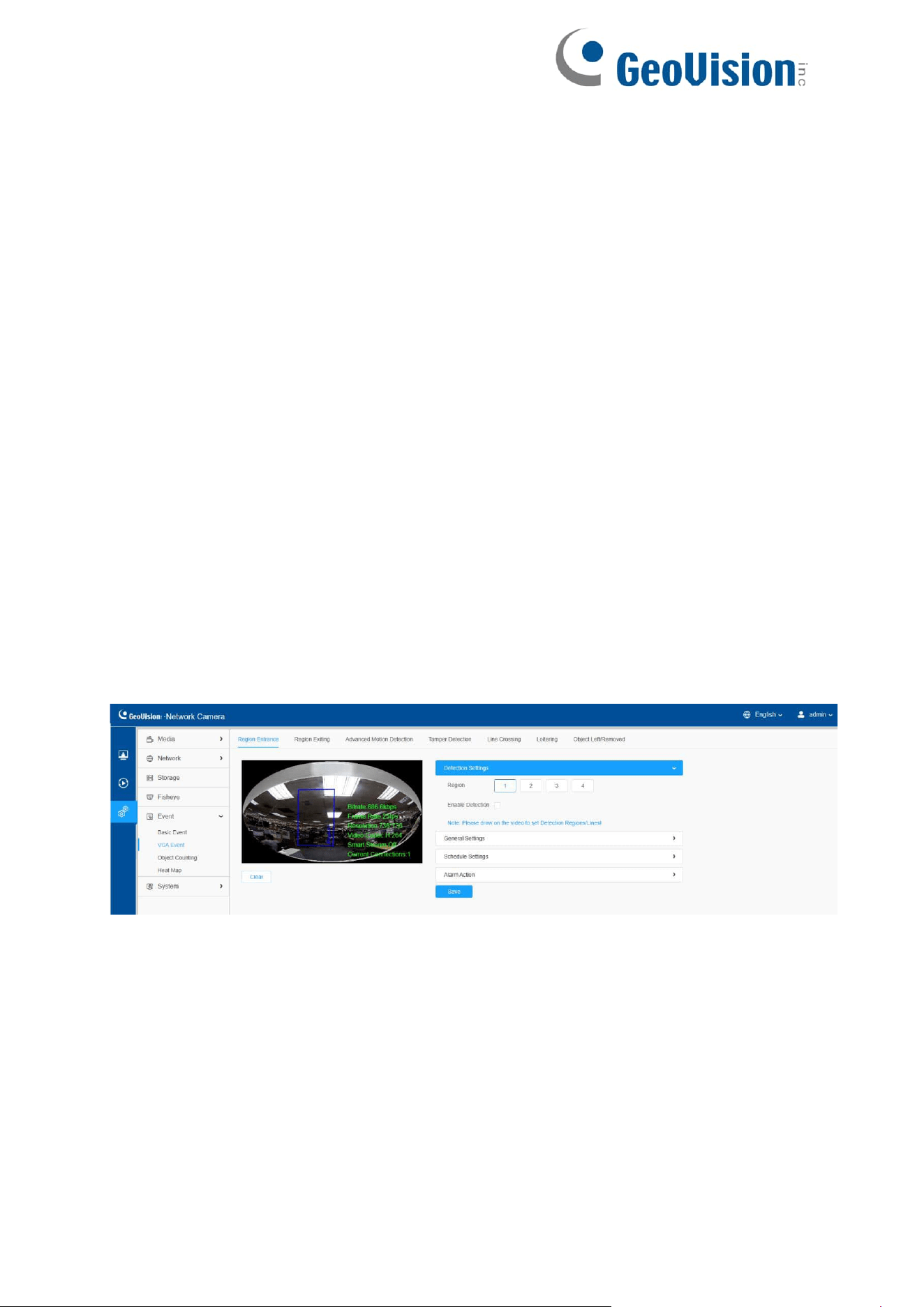
8.4.2.1 Region Entrance
Region entrance helps to protect a special area from potential threat of suspicious
person’s or object’s entrance. An alarm will be triggered when objects enter the selected
regions by enabling region entrance.
Settings steps are shown as follows:
[Detection Settings]
Note: General Settings will take effect in all detection regions/lines!
Step 1: Selected detection region.
93
Step 2: Enable region entrance detection.
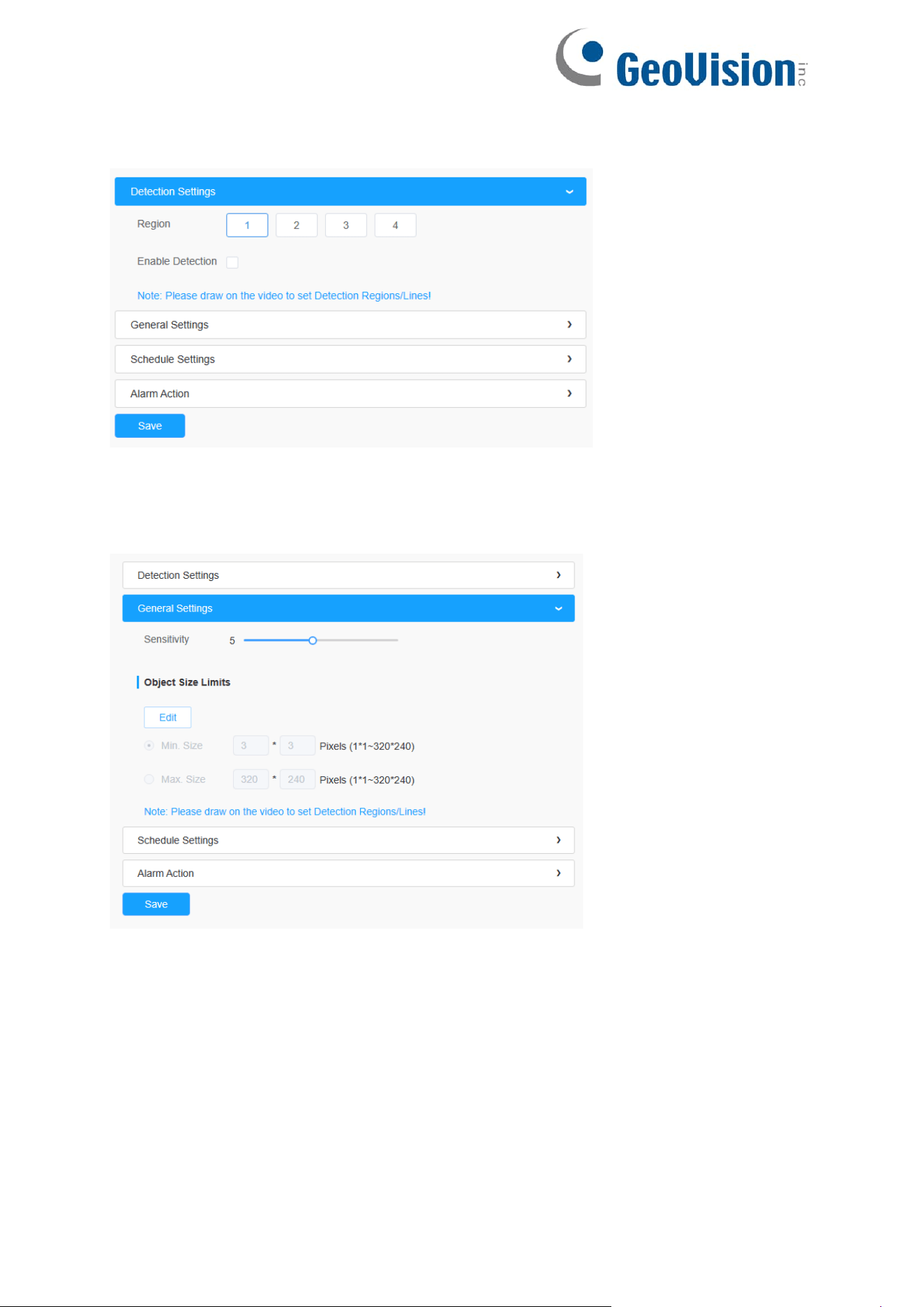
[General Settings]
Step 3: Set detecting sensitivity and object size limits;
94
Table 44. Description of the buttons
Parameters
Function Introduction
Sensitivity
Level 1~10 is available, the default level is 5. The higher the
sensitivity, the easier it is for moving objects to be recorded in
the results.
Min. Size
Draw the screen or input pixel number to set the minimum
size of the detected object. When the object is smaller than
this size, it will not be detected. The default minimum size is
3*3.
Max. Size
Draw the screen or input pixel number to set the maximum
size of the detected object. When the object is larger than
this size, it will not be detected. The default maximum size
is 320*240.
[Schedule Settings]
Step 4: Set detection schedule;
95
Table 45. Description of the buttons
Parameters
Function Introduction
Copy the schedule area to another date.
Select all schedule.
Clear all schedule.
[Alarm Action]
Step 5: Set alarm action;

96
Table 46. Description of the buttons
Parameters
Function Introduction
Record
Duration: Selected the duration time of alarm.
5s/10s/15s/20s/25s/30s are available.
Linkage: Save alarm recording files into SD Card or
NAS or Upload the recording files via FTP.
Snapshot
Number: The number of snapshots. 1~5 is available.
Interval: This cannot be edited unless you choose more
than 1 to Snapshot.
Linkage: Save alarm recording files into SD Card
or NAS, Upload the recording files via FTP and
send alarm email.
External Output
If the camera equips with External Output, you can
enable the action after configuring the trigger duration.
Play Audio
Auto/10 seconds/30 seconds/1 minute/5 minutes/10
minutes are available.
Note: Please enable the Audio Speaker.
Alarm to SIP Phone
Support to call the SIP phone after enabling the SIP
function.
Note: Please open the SIP.
HTTP Notification
Support to pop up the alarm news to specified HTTP URL.
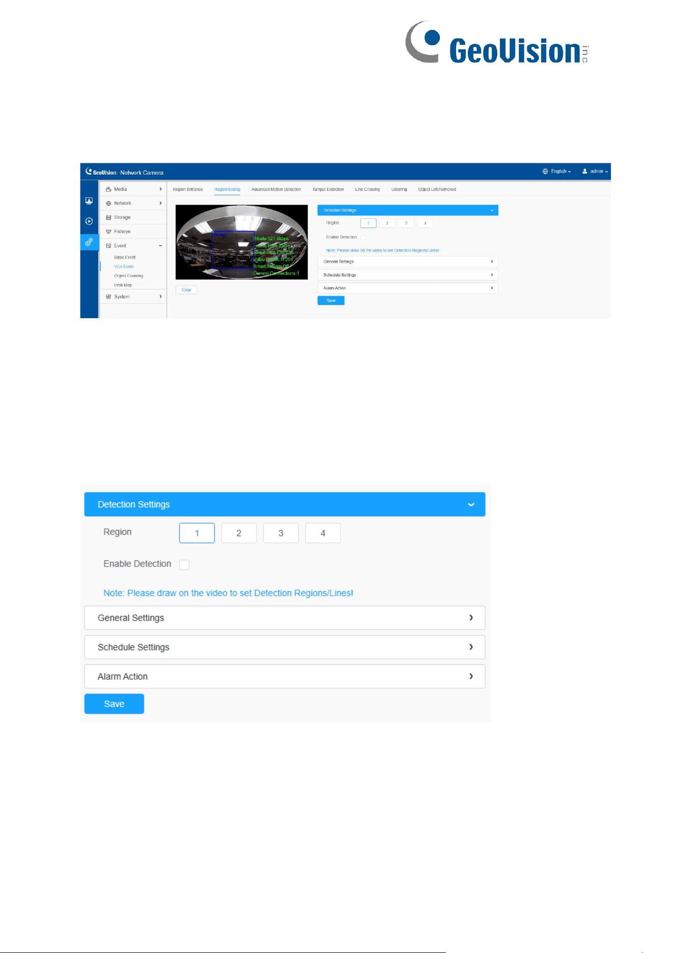
97
8.4.2.2 Region Exiting
Region exiting is to make sure that any person or object won't exit the area that is
being monitored. Any exit of people or objects will trigger an alarm.
Settings steps are shown as follows:
[Detection Settings]
Note: General Settings will take effect in all detection regions/lines!
Step 1: Selected detection region.
Step 2: Enable region exiting detection.
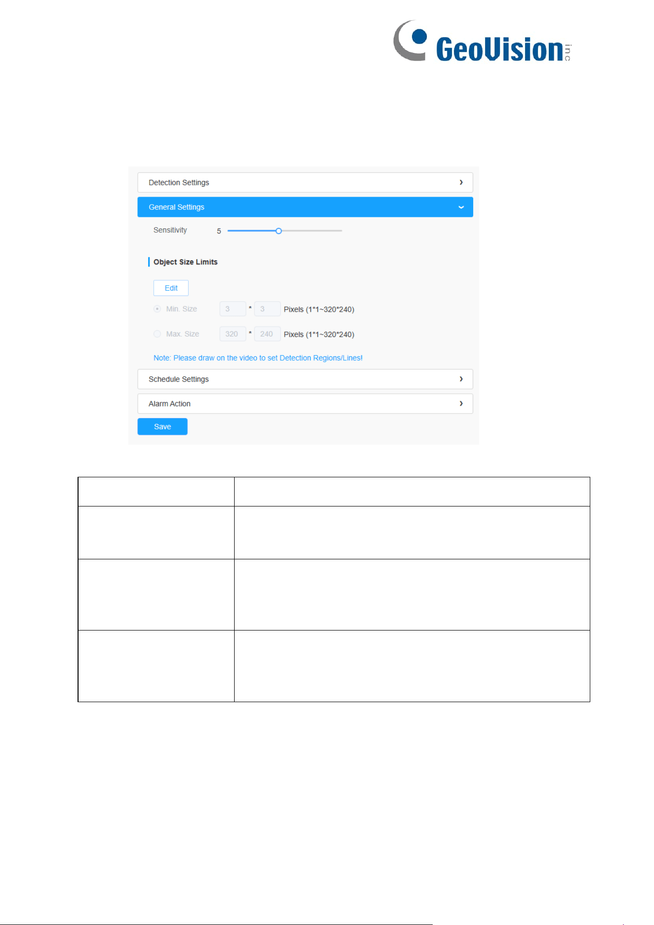
98
[General Settings]
Step 3: Set detecting sensitivity and object size limits;
Table 47. Description of the buttons
Parameters
Function Introduction
Sensitivity
Level 1~10 is available, the default level is 5. The higher
the sensitivity, the easier it is for moving objects to be
recorded in the results.
Min. Size
Draw the screen or input pixel number to set the minimum
size of the detected object. When the object is smaller
than this size, it will not be detected. The default minimum
size is 3*3.
Max. Size
Draw the screen or input pixel number to set the maximum
size of the detected object. When the object is larger than
this size, it will not be detected. The default maximum size
is 320*240.
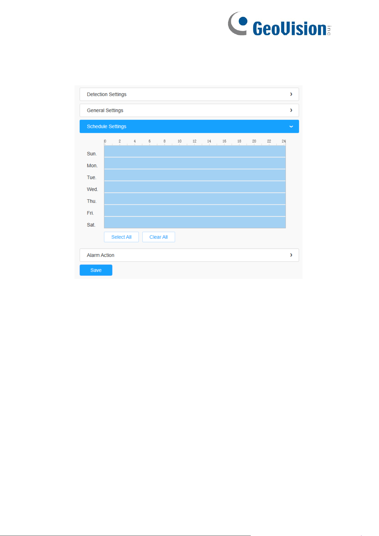
99
[Schedule Settings]
Step 4: Set detection schedule;
Note: This part is the same as the regular schedule settings. You can refer to
8.4.2.1 Region Entrance.
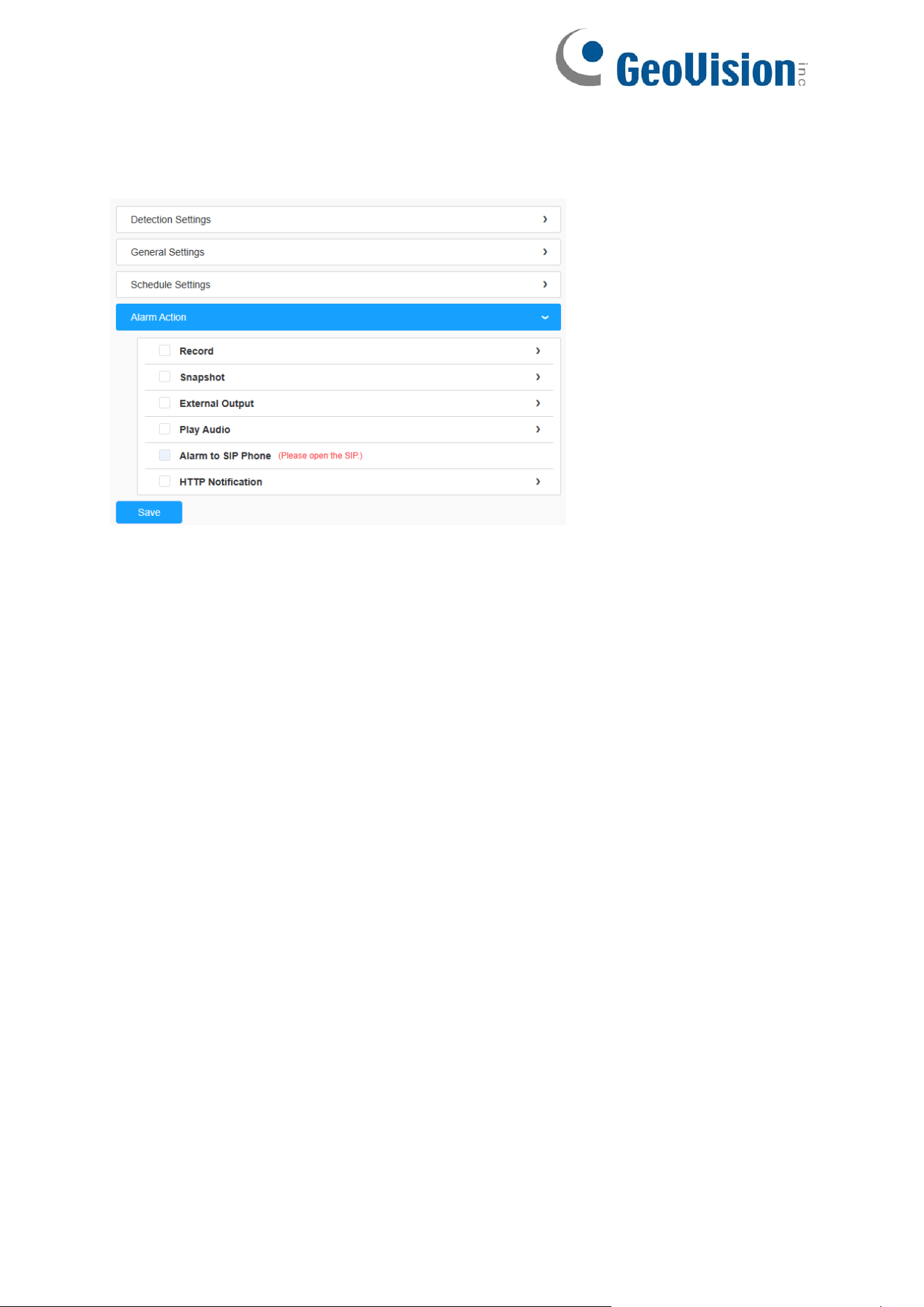
100
[Alarm Action]
Step 5: Set alarm action;
Note: This part is the same as the regular alarm settings.
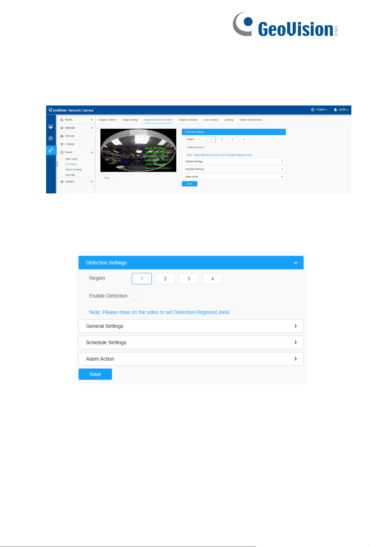
101
8.4.2.3 Advanced Motion Detection
Different from traditional motion detection, advanced motion detection can filter out
“noise” such as lighting changes, natural tree movements, etc. When an object moves
in the selected area, it will trigger alarm.
Settings steps are shown as follows:
Step 1: Selected detection region.
Step 2: Enable advanced motion detection.
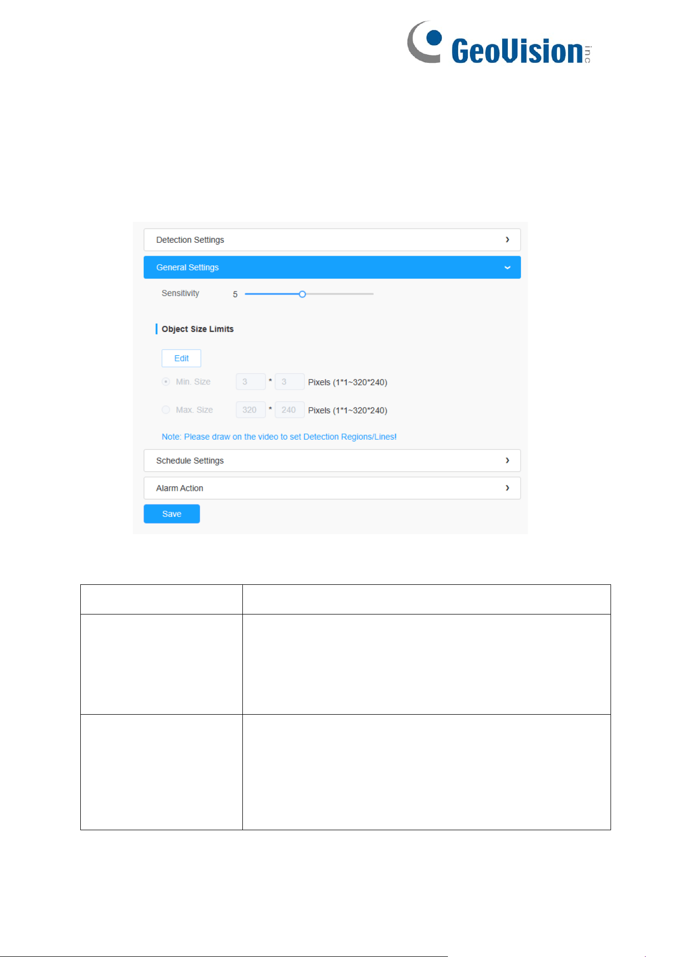
102
[General Settings]
Step 3: Set Ignore Short-Lived Motion time. If you set the time, when the moving
duration of an object is within the setting time, the alarm will not be triggered;
Step 4: Set detecting sensitivity and object size limits;
Table 48. Description of the buttons
Parameters
Function Introduction
Ignore Short-Lived
Motion
The alarm will not be triggered when the moving duration of
an object is within the setting time. Off/1s/2s/3s/4s/5s are
available.
Note: Ignore Short-Lived Motion time is to avoid false
alarm caused by
instant object movement within time
setting.
Sensitivity
Level 1~10 is available, the default level is 5. The higher
the sensitivity, the easier it is for moving objects to be
recorded in the results.
Note: The sensitivity can be configured to detect various
movement according to different requirements. When the
level of sensitivity is low, slight
movement won’ t trigger
the alarm.

103
Min. Size
Draw the screen or input pixel number to set the minimum
size of the detected object. When the object is smaller
than this size, it will not be detected. The default minimum
size is 3*3.
Max. Size
Draw the screen or input pixel number to set the maximum
size of the detected object. When the object is larger than
this size, it will not be detected. The default maximum size
is 320*240.
[Schedule Settings]
Step 5: Set detection schedule;
Note: This part is the same as the regular schedule settings. You can refer to
8.4.2.1 Region Entrance.
[Alarm Action]
Step 6: Set alarm action;
Note:
This part is the same as the regular alarm settings.
If you enable External Output and choose Constant External Output Action
Time, when object motion time is longer than the Ignore Short-Lived
Motion time which you set in the selected regions, External Output Action
alarm time will be always constant till the alarm is released.
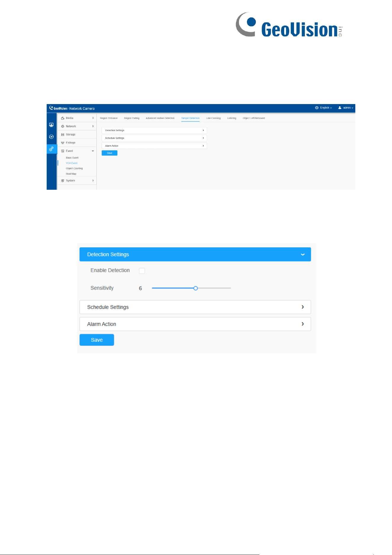
104
8.4.2.4 Tamper Detection
Tamper Detection is used to detect possible tampering like the camera being unfocused,
obstructed or moved. This functionality alerts security staff immediately when any above-
mentioned actions occur.
Settings steps are shown as follows:
Step 1: Enable Tamper Detection and set detecting sensitivity;
[Schedule Settings]
Step 2: Set detection schedule;
Note: This part is the same as the regular schedule settings. You can refer to
8.4.2.1 Region Entrance.
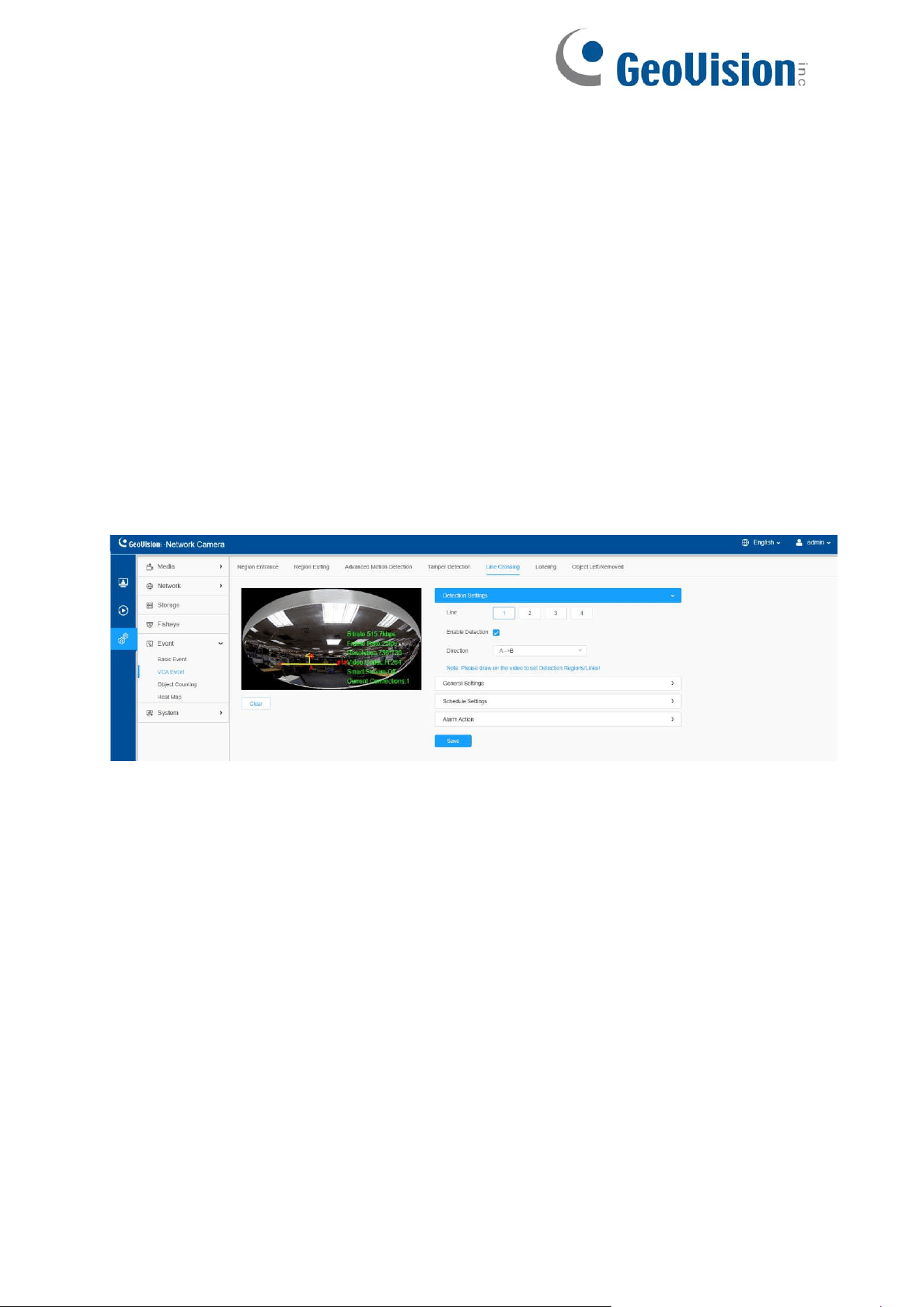
105
[Alarm Action]
Step 3: Set alarm action;
Note:
This part is the same as the regular alarm settings.
If you enable External Output and choose Constant External Output Action
Time, when possible tampering is detected, External Output Action alarm
time will be always constant till the alarm is released.
The algorithm supports defocus detection in Tamper Detection function.
8.4.2.5 Line Crossing
Line Crossing detection is designed to work in most indoor and outdoor environment.
An event will be triggered every time when the camera detects objects crossing a
defined virtual line.
Settings steps are shown as follows:
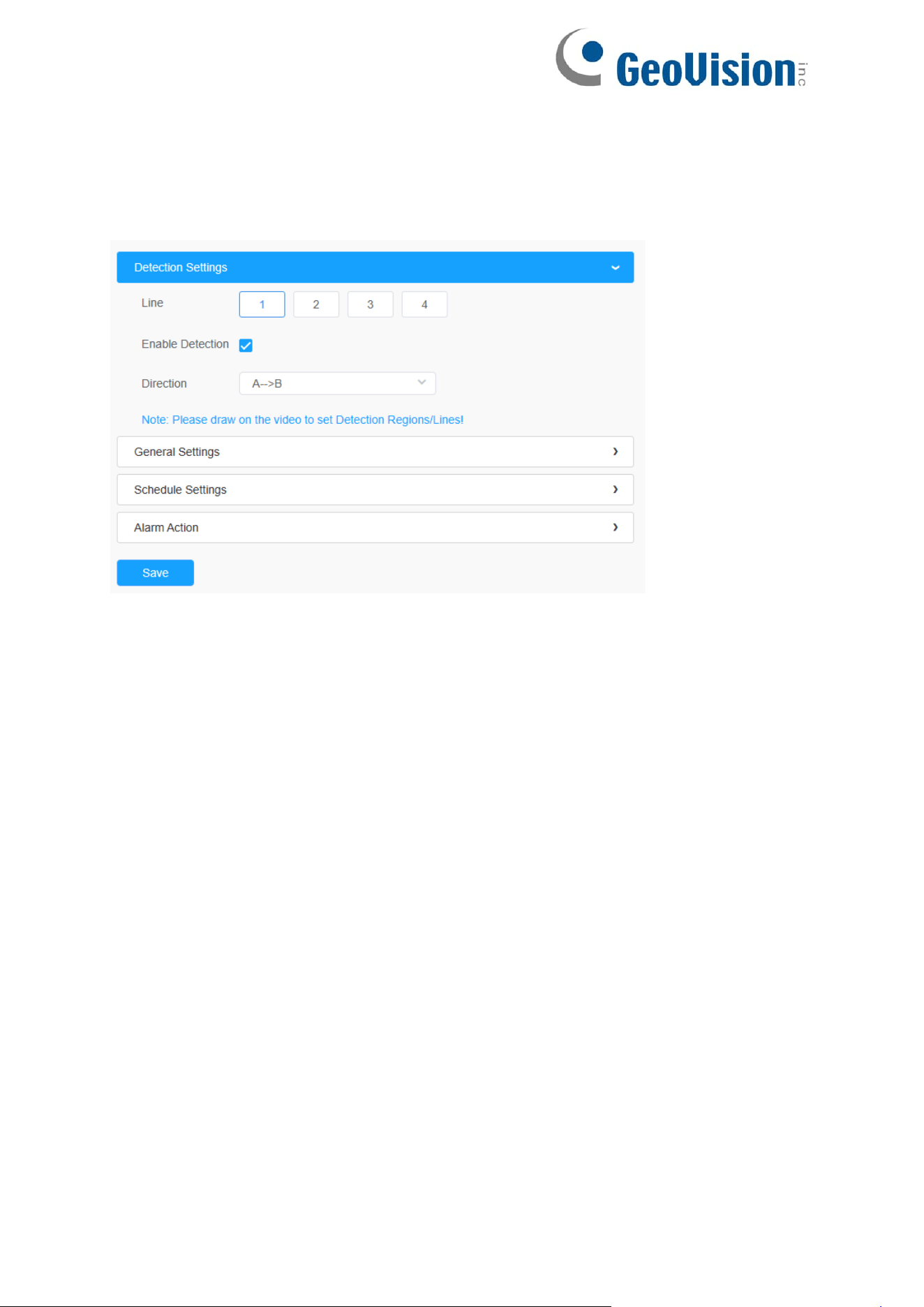
106
[Detection Settings]
Step 1: Selected detection line.
Step 2: Enable line crossing detection and define its direction.
Note:
Allows to set up to four lines at a time. There are three direction modes to
choose for triggering alarm. “A→B” means when there is any object crossing
the line from the “A” side to the “B” side, the alarm will be triggered. “B→A” vice
versa. “A ↔ B” means that the alarm will be triggered when objects cross line
from either side.
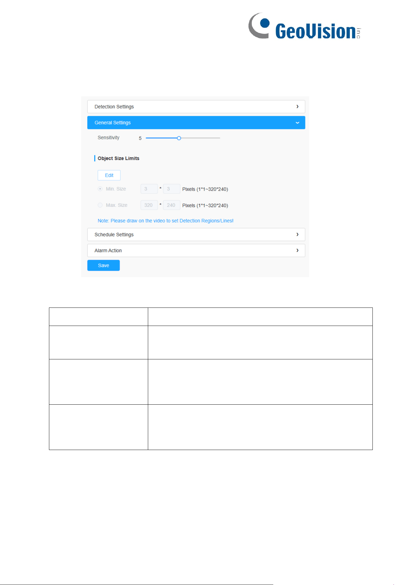
107
[General Settings]
Step 3: Set detecting sensitivity and object size limits;
Table 49. Description of the buttons
Parameters
Function Introduction
Sensitivity
Level 1~10 is available, the default level is 5. The higher
the sensitivity, the easier it is for moving objects to be
recorded in the results.
Min. Size
Draw the screen or input pixel number to set the minimum
size of the detected object. When the object is smaller
than this size, it will not be detected. The default
minimum size is 3*3.
Max. Size
Draw the screen or input pixel number to set the maximum
size of the detected object. When the object is larger than
this size, it will not be detected. The default maximum size
is 320*240.
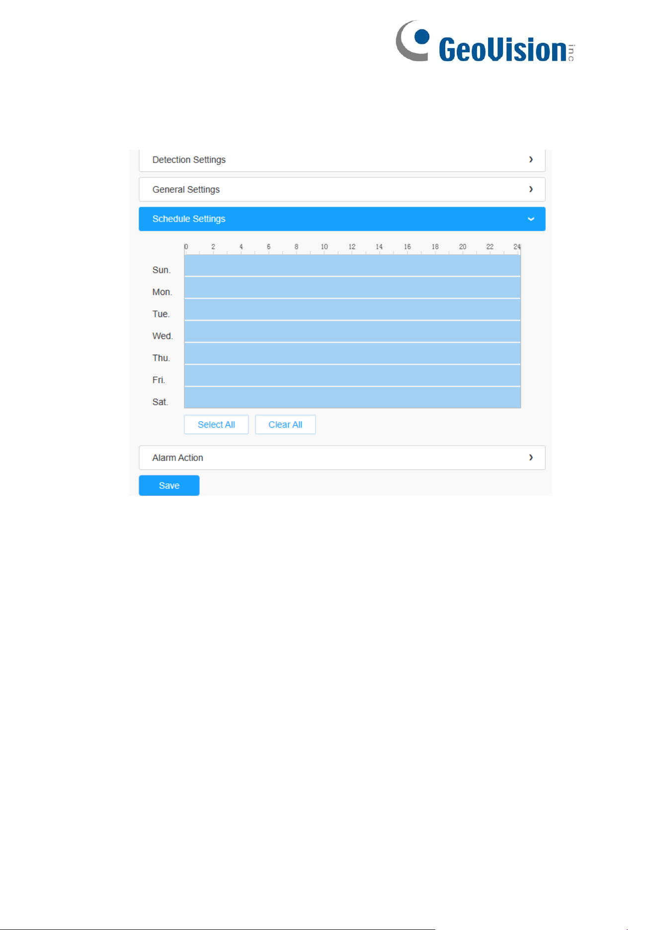
108
[Schedule Settings]
Step 4: Set detection schedule;
Note: This part is the same as the regular schedule settings. You can refer to 8.4.2.1
Region Entrance.
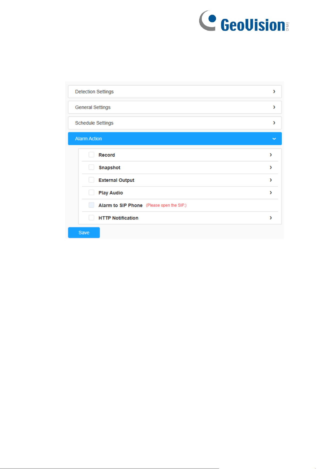
109
[Alarm Action]
Step 5: Set alarm action;
Note:
This part is the same as the regular alarm settings.
If you enable External Output and choose Constant External Output Action
Time, when objects cross a defined virtual line, External Output Action alarm
time will be always constant till the alarm is released
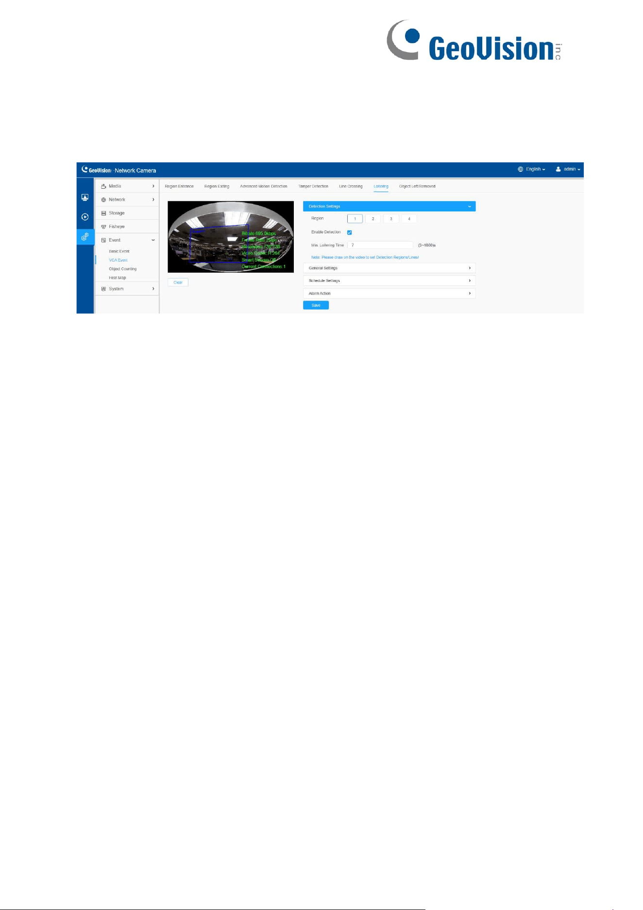
110
8.4.2.6 Loitering
When objects are loitering in a defined area for a specific period of time, it would trigger
an alarm.
Settings steps are shown as follows:
[Detection Settings]
Note: General Settings will take effect in all detection regions/lines!
Step 1: Selected detection region.
Step 2: Enable loitering detection.
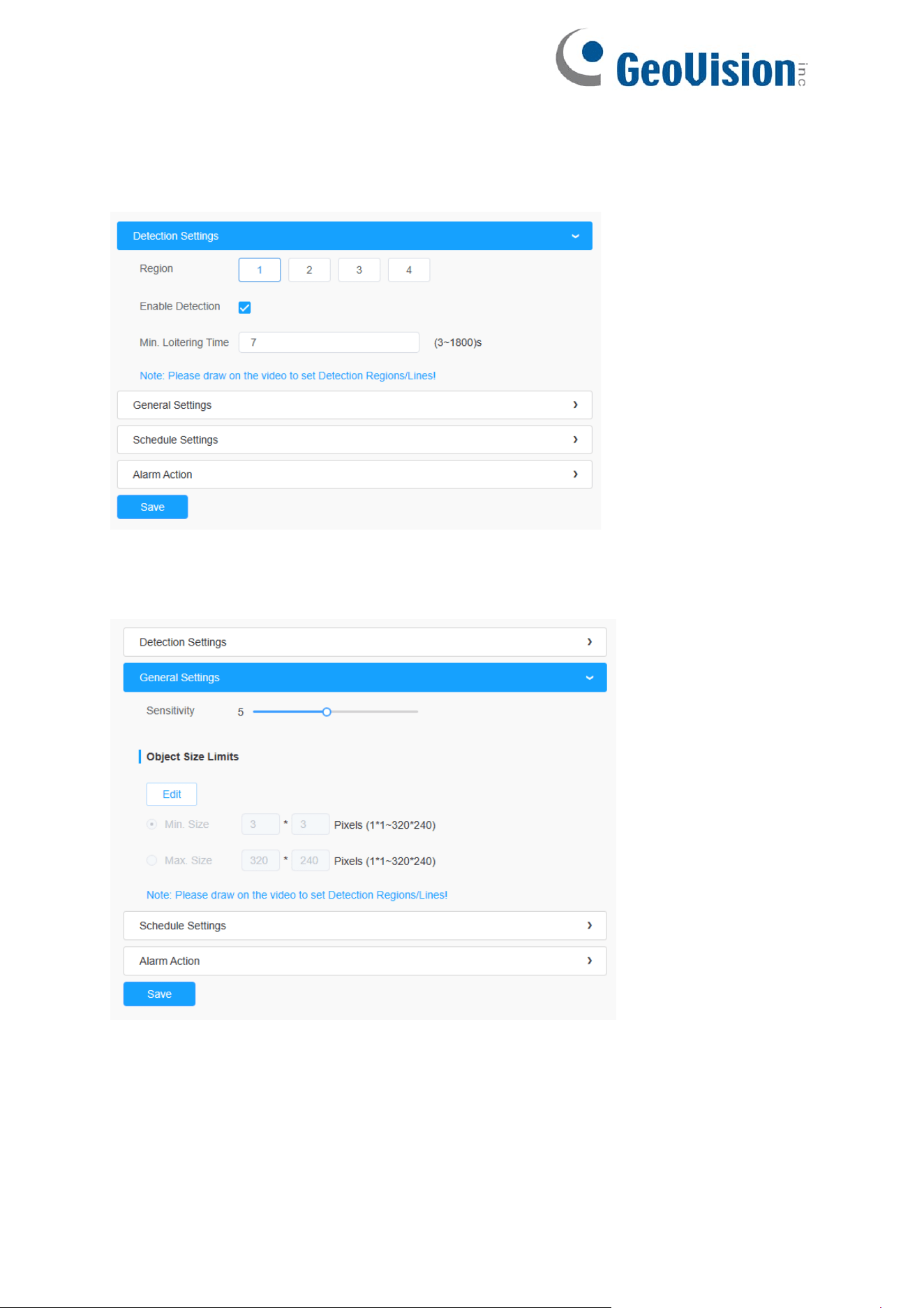
111
Step 3: Set Min. Loitering Time. After setting minimum loitering time from 3s to 1800s,
any objects loitering in the selected area over the minimum loitering time will trigger the
alarm;
[General Settings]
Step4: Set object size limits;
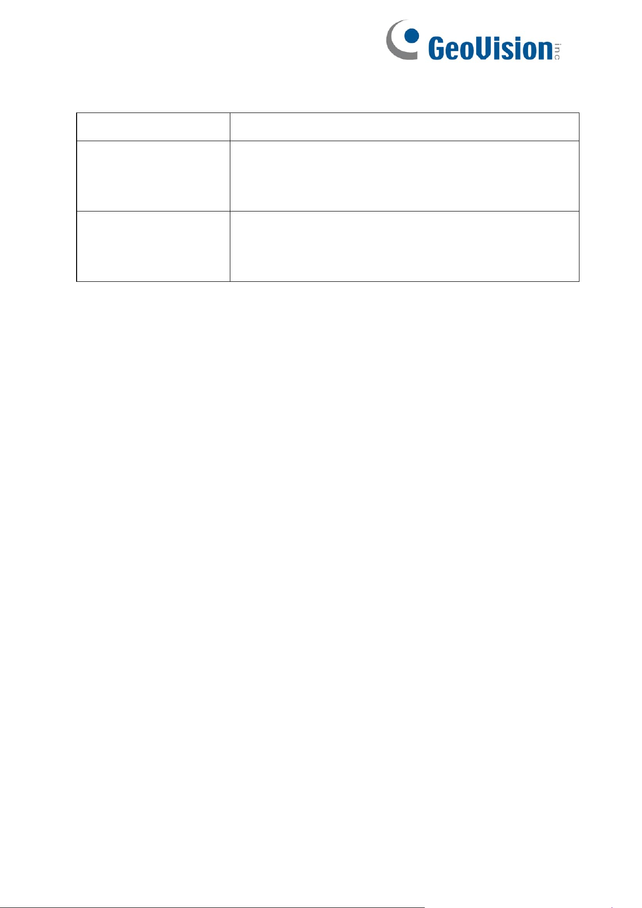
112
Table 50. Description of the buttons
Parameters
Function Introduction
Min. Size
Draw the screen or input pixel number to set the minimum
size of the detected object. When the object is smaller
than this size, it will not be detected. The default minimum
size is 3*3.
Max. Size
Draw the screen or input pixel number to set the maximum
size of the detected object. When the object is larger than
this size, it will not be detected. The default maximum size
is 320*240.
[Schedule Settings]
Step 4: Set detection schedule;
Note: This part is the same as the regular schedule settings. You can refer to
8.4.2.1 Region Entrance.
[Alarm Action]
Step 5: Set alarm action;
Note:
• This part is the same as the regular alarm settings.
• If you enable External Output and choose Constant External Output Action
Time, when objects loiter in the selected regions, External Output Action
alarm time will be always constant till the alarm is released.
Step 5: Set alarm settings. If you enable External Output and choose Constant External
Output Action Time, when objects loiter in the selected regions, External Output Action
alarm time will be always constant till the alarm is released.
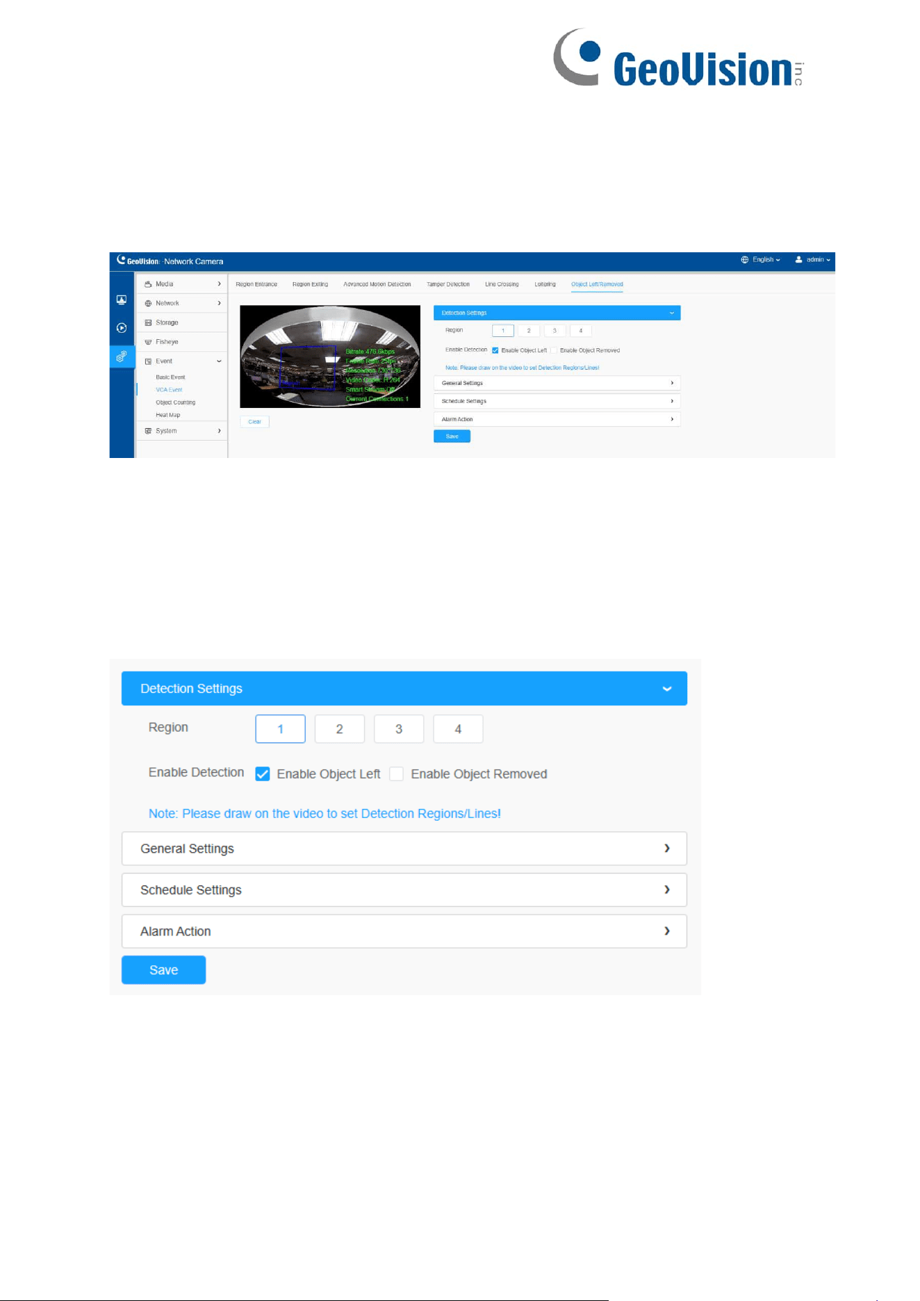
113
8.4.2.7 Object Left/Removed
Object Left can detect and prompt an alarm if an object is left in a pre-defined
region. Object Removed can detect and prompt an alarm if an object is removed
from a pre-defined region.
Settings steps are shown as follows:
[Detection Settings]
Note: General Settings will take effect in all detection regions/lines!
Step 1: Selected detection region and enable object left/removed detection (Or you
can enable both features at the same time);
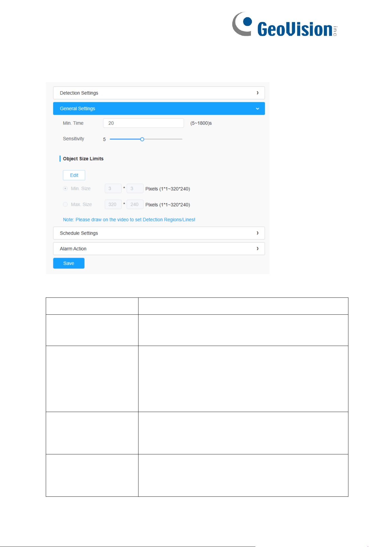
114
[General Settings]
Step 2: Set Min. time, detecting sensitivity and object size limits.
Table 51. Description of the buttons
Parameters
Function Introduction
Min. Time
After setting Min. time from 5s to 1800s, any objects are
left in the selected area or removed from the selected area
over the minimum time will trigger the alarm.
Sensitivity
Level 1~10 is available, the default level is 5. The higher
the sensitivity, the easier it is for moving objects to be
recorded in the results.
Note: The sensitivity can be configured to detect various
movement according to different requirements. When the
level of sensitivity is low, slight
movement won’ t trigger
the alarm.
Min. Size
Draw the screen or input pixel number to set the minimum
size of the detected object. When the object is smaller
than this size, it will not be detected. The default
minimum size is 3*3.
Max. Size
Draw the screen or input pixel number to set the maximum
size of the detected object. When the object is larger than
this size, it will not be detected. The default maximum size
is 320*240.

115
[Schedule Settings]
Step 5: Set detection schedule;
Note: This part is the same as the regular schedule settings. You can refer to
8.4.2.1 Region Entrance.
[Alarm Action]
Step 6: Set alarm action;
Note:
This part is the same as the regular alarm settings.
If you enable External Output and choose Constant External Output
Action Time, when an object is left/removed from the selected regions,
External Output Action alarm time will be always constant till the alarm
is released.
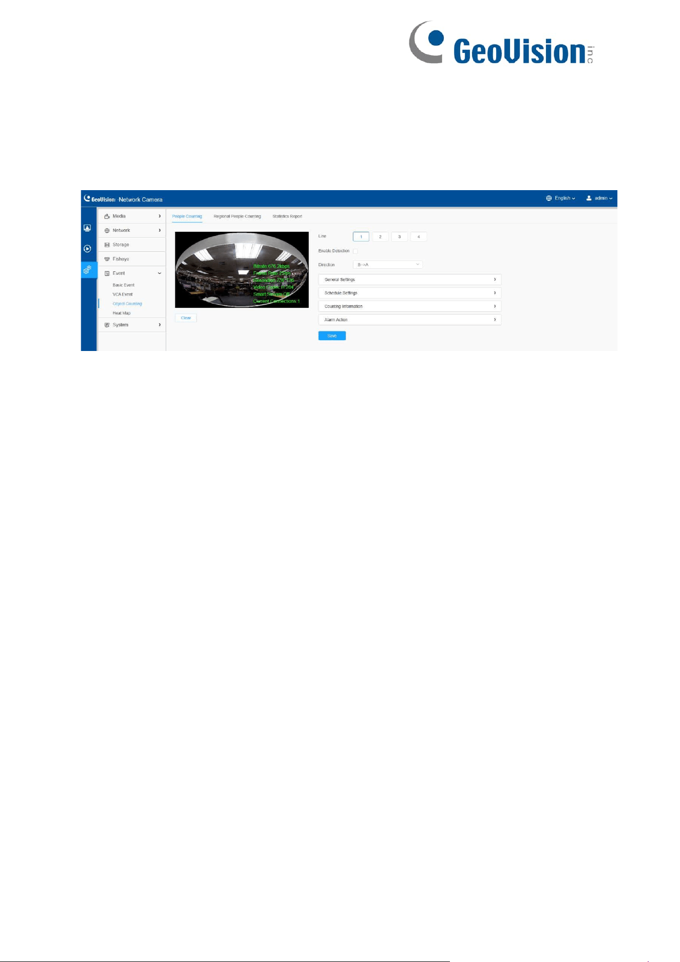
116
8.4.3 Object Counting
8.4.3.1 People Counting
People Counting is able to count how many people enter or exit during the setting period.
Settings steps are as shown below:
Step 1: Enable People Counting;
Step 2: Set detection line and direction.
Note:
•
Crossing along the direction of the arrow will record as “In” , opposite is
“Out”.
•
Support up to 4 detection lines.
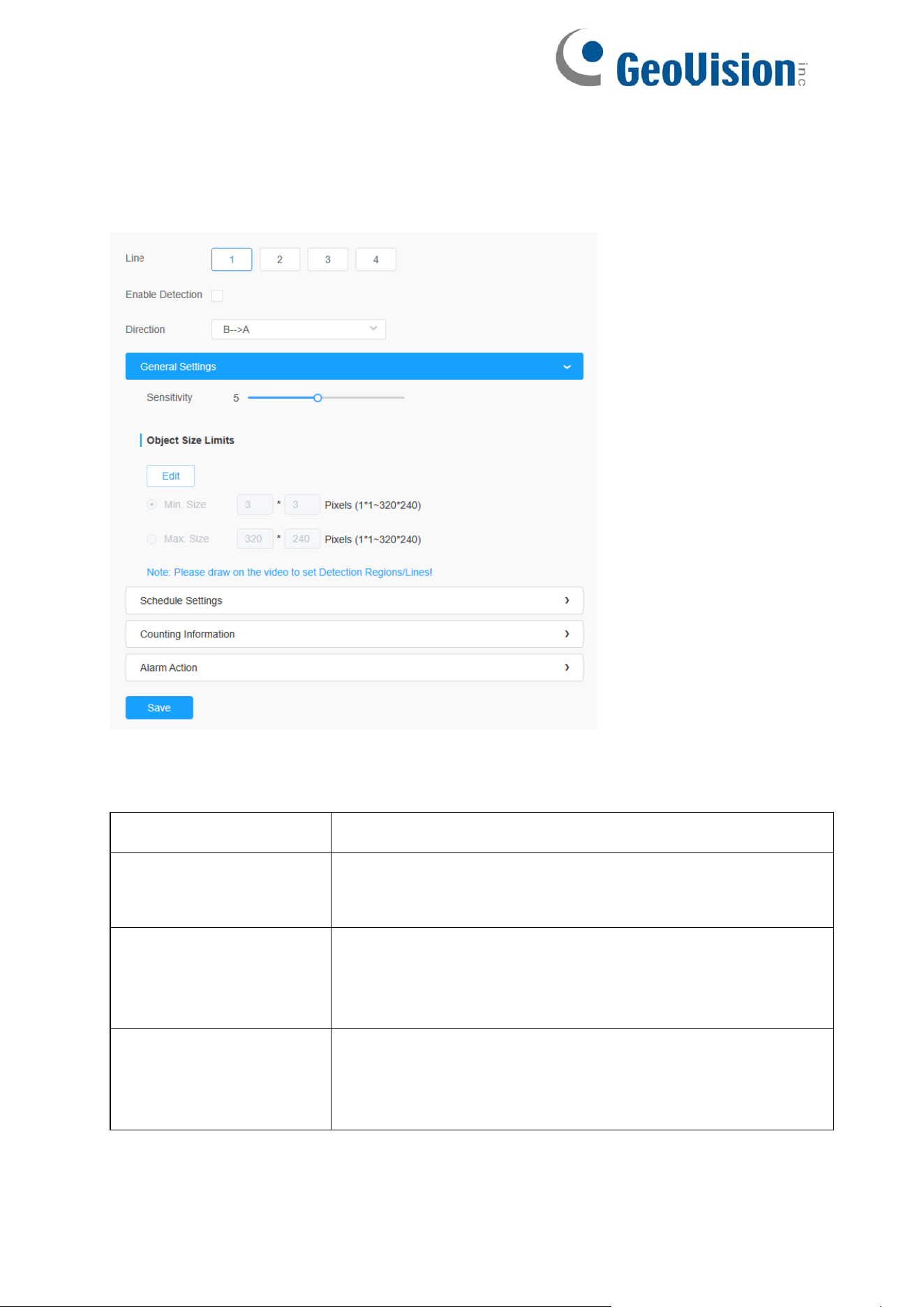
117
[General Settings]
Step 3: Set sensitivity and object size limits.
Table 52. Description of the buttons
Parameters
Function Introduction
Sensitivity
Level 1~10 is available, the default level is 5. The higher
the sensitivity, the easier it is for moving objects to be
recorded in the results.
Min. Size
Draw the screen or input pixel number to set the minimum
size of the detected object. When the object is smaller
than this size, it will not be detected. The default minimum
size is 3*3.
Max. Size
Draw the screen or input pixel number to set the maximum
size of the detected object. When the object is larger than
this size, it will not be detected. The default maximum size
is 320*240.
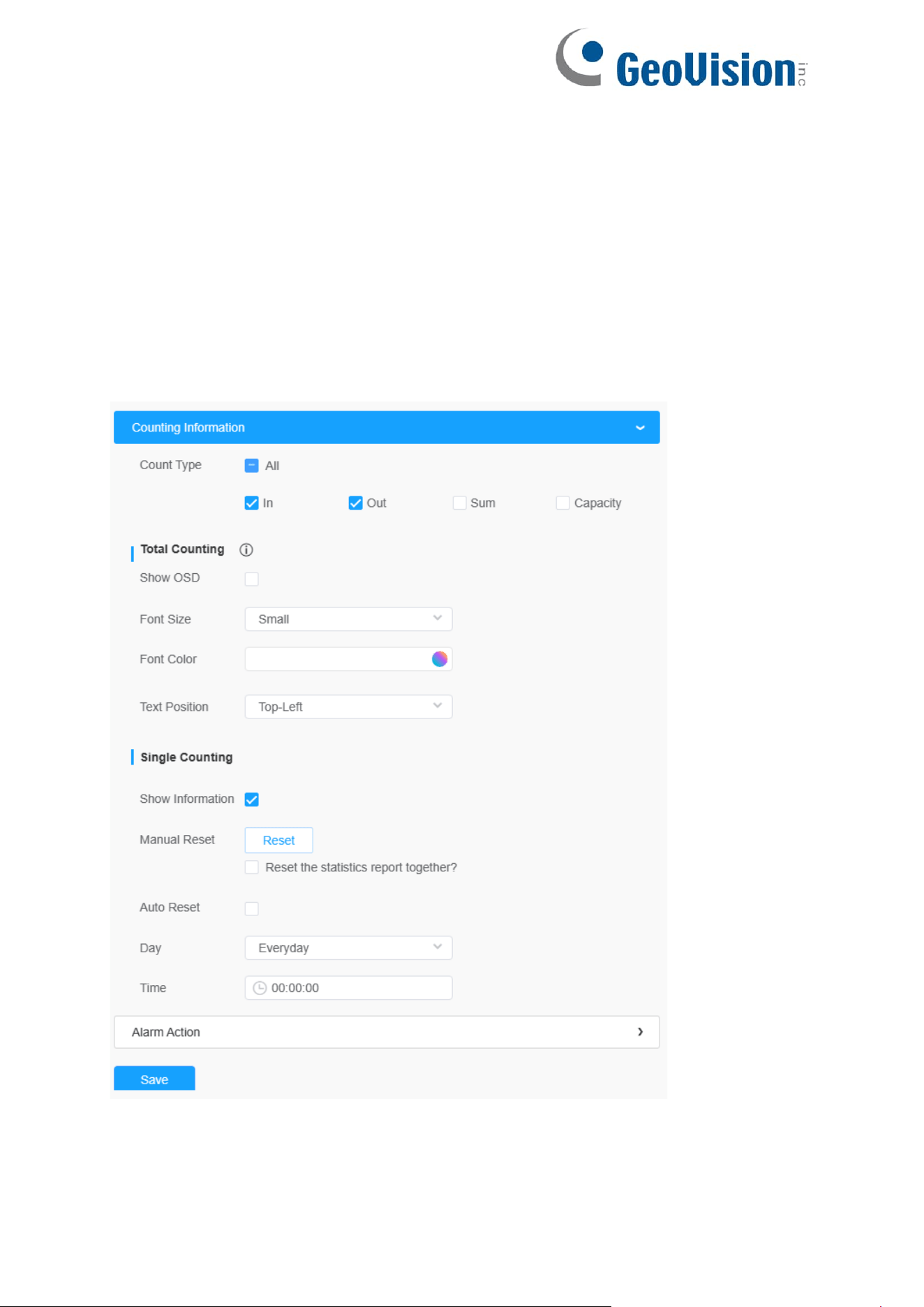
118
[Schedule Settings]
Step 4: Set detection schedule;
Note: This part is the same as the regular schedule settings. You can refer to
8.4.2.1 Region Entrance.
[Counting Information]
Step 5: Set counting information;

119
Table 53. Description of the buttons
Parameters
Function Introduction
Count Type
Users can choose the information they want to display in Live
Video.
Total Counting
Set counting OSD.
Note: The Total Counting OSD configuration is linked in
all detection lines. Show OSD: Click to enable/disable the
OSD shown.
Font Size: The font size of the OSD display.
Font Color: The font color of the OSD display.
Text Position: The text position of the OSD display.
Single Counting
Set Single Counting.
Note: The Total Counting OSD configuration is linked in
all detection lines.
Show Information: Click to show the information.
Manual Reset: Reset the counting of each single line.
You can choose to reset the statistics report together.
Auto Reset: It is used to automatically clear the single
counting information. Day: The day of Auto Reset.
Time: The time of Auto Reset.
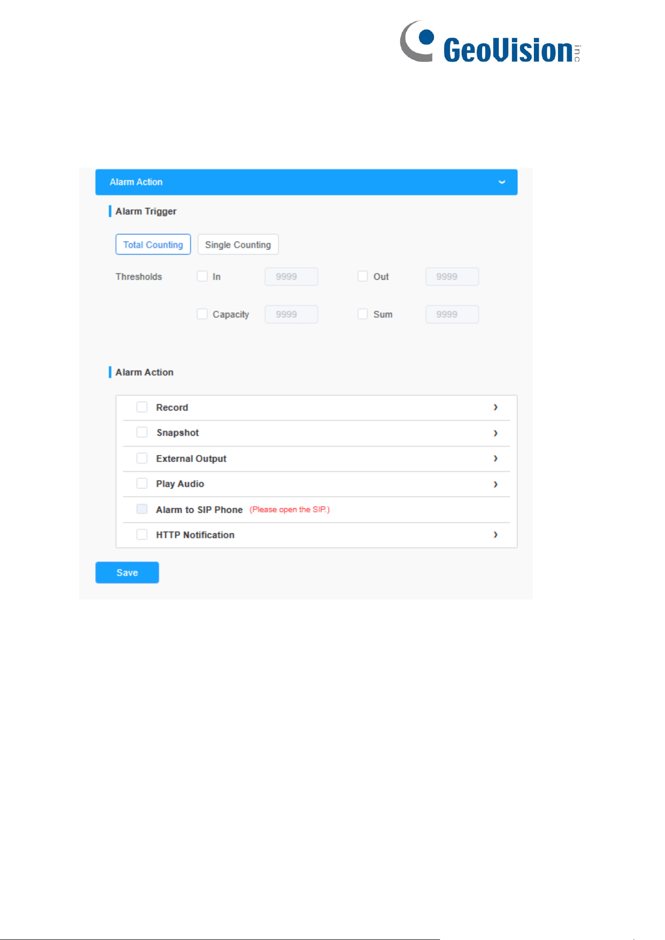
120
[Alarm Action]
Step6: Set alarm trigger and alarm action;

121
Table 54. Description of the buttons
Parameters
Function Introduction
Alarm Trigger
Alarm will be triggered when the threshold reaches to a
certain value from 1 to 9999. Total Counting and Single
Counting are available. You can set the Alarm Thresholds
of In/Out/Capacity/Sum.
Note:
For Total Counting, the thresholds are the
sum of the total number of 4 detection lines.
For Single Counting, the threshold is for the
selected detection line.
Alarm Action
This part is the same as the regular alarm settings.
Note:
The alarm action is effective on 4 detection lines
simultaneously.
If you enable External Output and choose
Constant External Output Action Time, when the
thresholds reach to a certain value you set,
External Output Action alarm time will be always
constant till the alarm is released.
8.4.3.2 Regional People Counting
When enabling Regional People Counting, users can check the real-time number of
people and the time of each person's stay in the detection region.
Note:
•
Support up to 4 detection regions for regional people counting.
• Users can check the real-time number of people and the time of each
person's stay in the detection region on Live View interface.
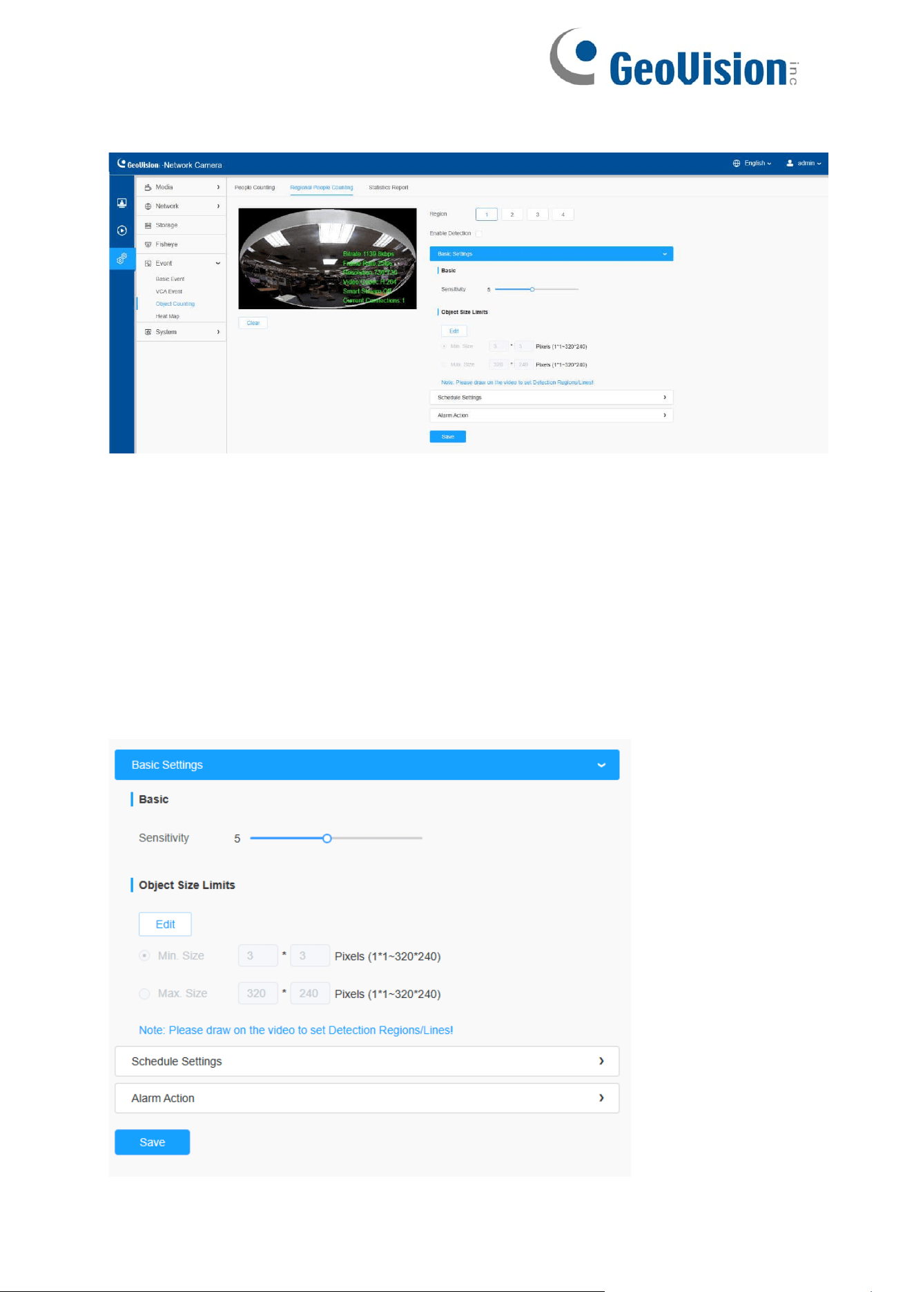
122
Settings steps are as shown below:
Step 1: Select Detection Region and enable regional people counting detection;
Note: Support up to 4 detection regions.
[Basic Settings]
Step 2: Set sensitivity and object size limits.
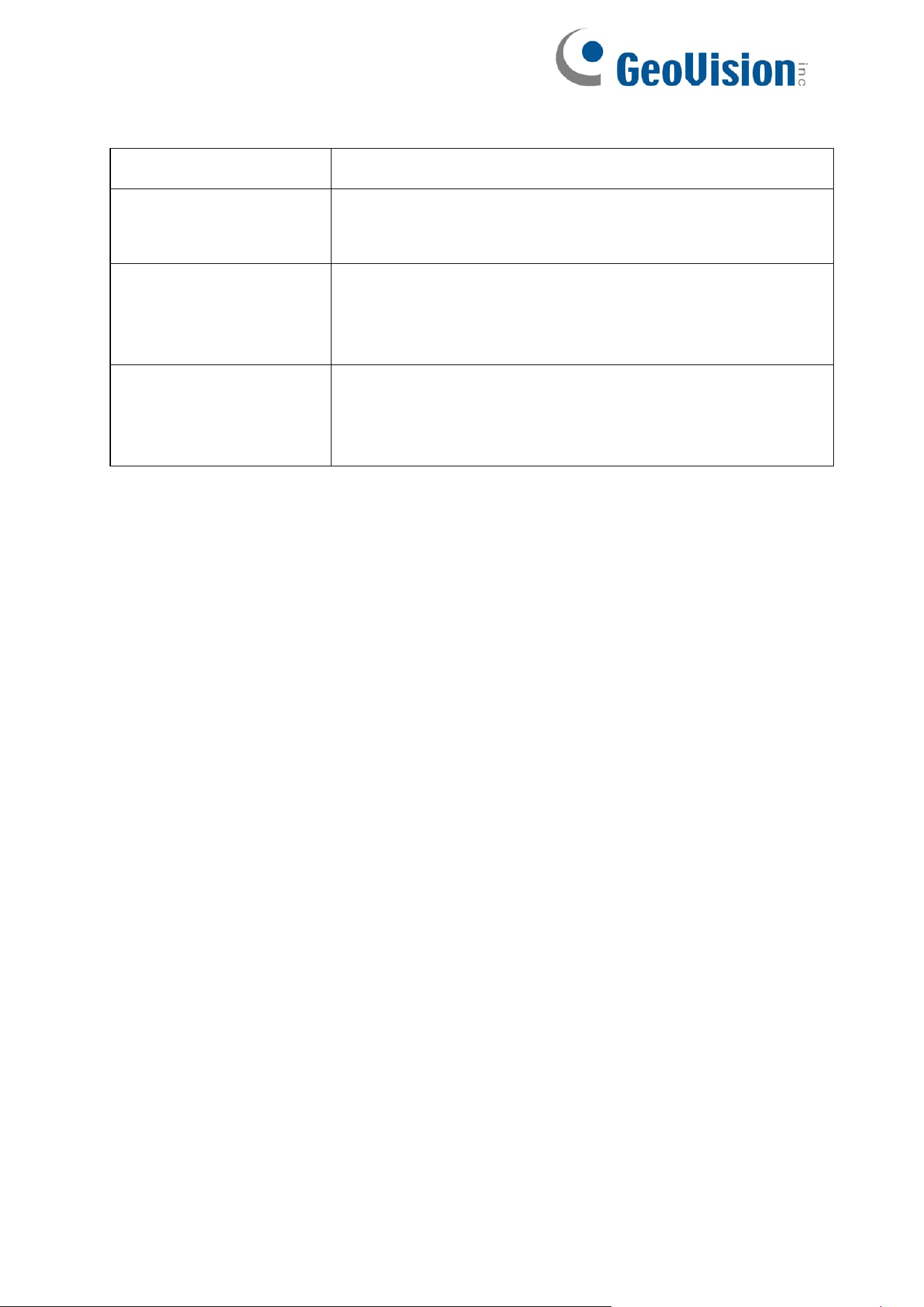
123
Table 55. Description of the buttons
Parameters
Function Introduction
Sensitivity
Level 1~10 is available, the default level is 5. The higher
the sensitivity, the easier it is for moving objects to be
recorded in the results.
Min. Size
Draw the screen or input pixel number to set the minimum
size of the detected object. When the object is smaller
than this size, it will not be detected. The default minimum
size is 3*3.
Max. Size
Draw the screen or input pixel number to set the maximum
size of the detected object. When the object is larger than
this size, it will not be detected. The default maximum size
is 320*240.
[Schedule Settings]
Step 4: Set detection schedule;
Note: This part is the same as the regular schedule settings. You can refer to
8.4.2.1 Region Entrance.
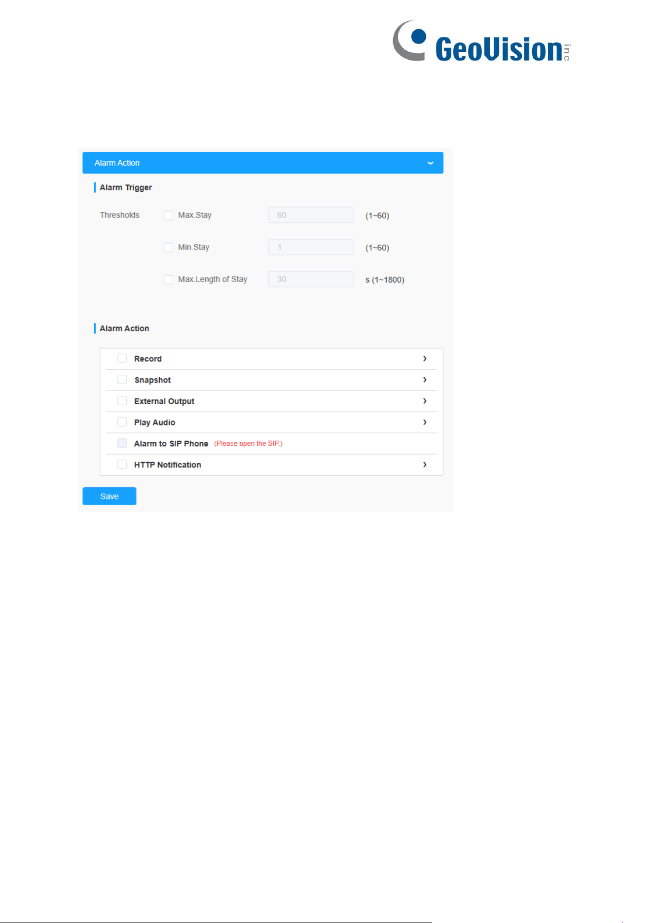
124
[Alarm Action]
Step 6: Set alarm trigger and alarm action;

125
Table 56. Description of the buttons
Parameters
Function Introduction
Alarm Trigger
Alarm will be triggered when the Max./Min. Stay/Max.
Length of Stay thresholds reaches to the value.
Note: The value must be in the range of 1 to 60.
Alarm Action
This part is the same as the regular alarm settings.
Note:
The alarm action is effective on 4 detection regions
simultaneously.
If you enable External Output and choose
Constant External Output Action Time, when the
thresholds reach to a certain value you set,
External Output Action alarm time will be always
constant till the alarm is released.
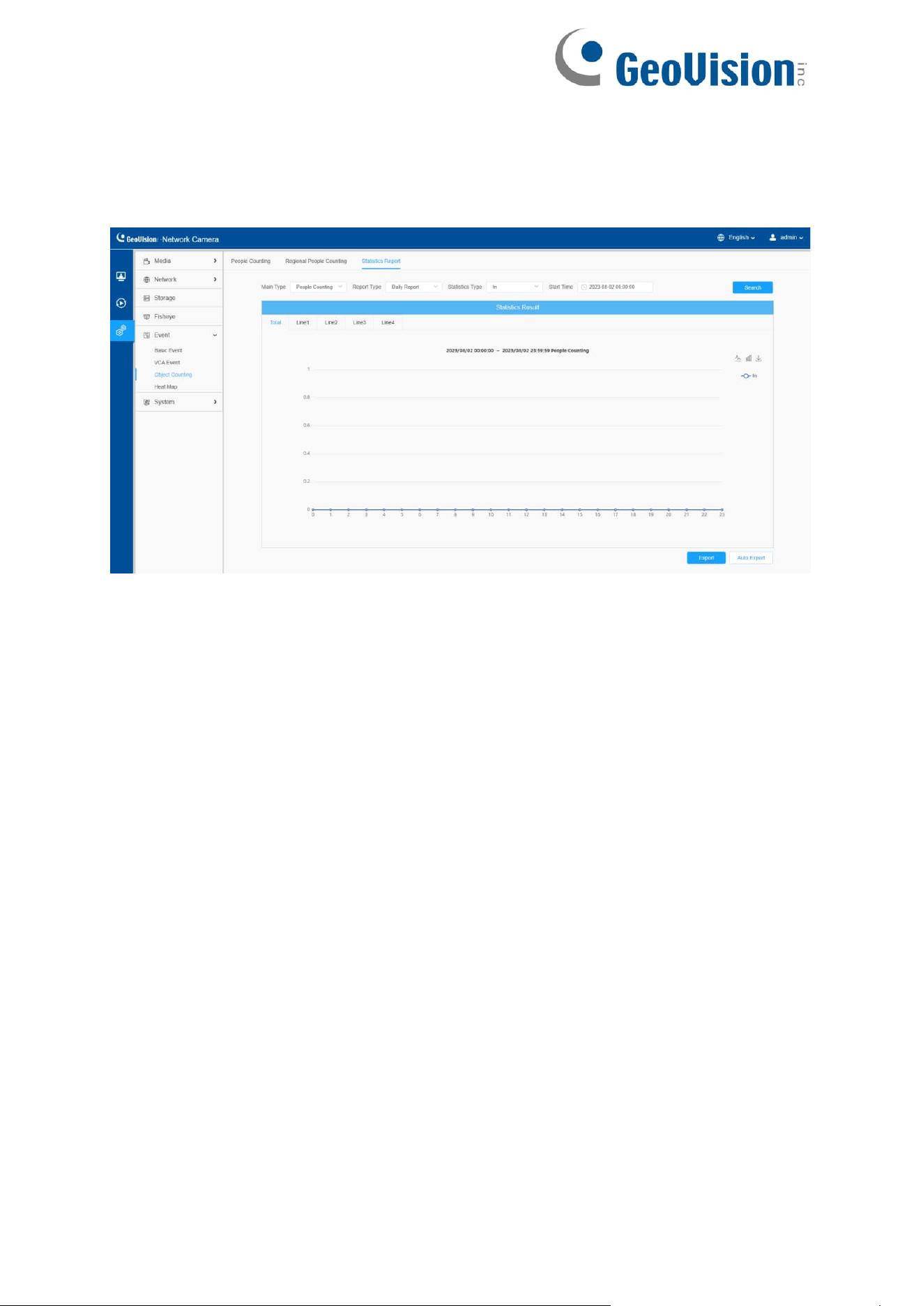
126
8.4.3.3 Statistics Report
The results during the enabling period will be displayed on “Statistics Report” interface.
Step 1: Select Main Type;
Step 2: Select Report Type including Daily Report, Weekly Report, Monthly Report
and Annual Report;
Step 3: For people counting, select Statistics Type including In, Out and Sum. For
regional people counting, select Length of Stay including All, More Than and Less
Than and set the time.
Note: For regional people counting, check the check box to search the report of
regions as needed.
Step 4: Select Start Time, then click "Search" button, the camera will automatically
count the data for the day/ week/ month/ year (based on the report type selected by the
user) from the start time and generate the corresponding report.
Step 5: Moreover, you can also click "Line Chart" or "Bar Chart" to switch display mode
of Statistics Report as shown below.
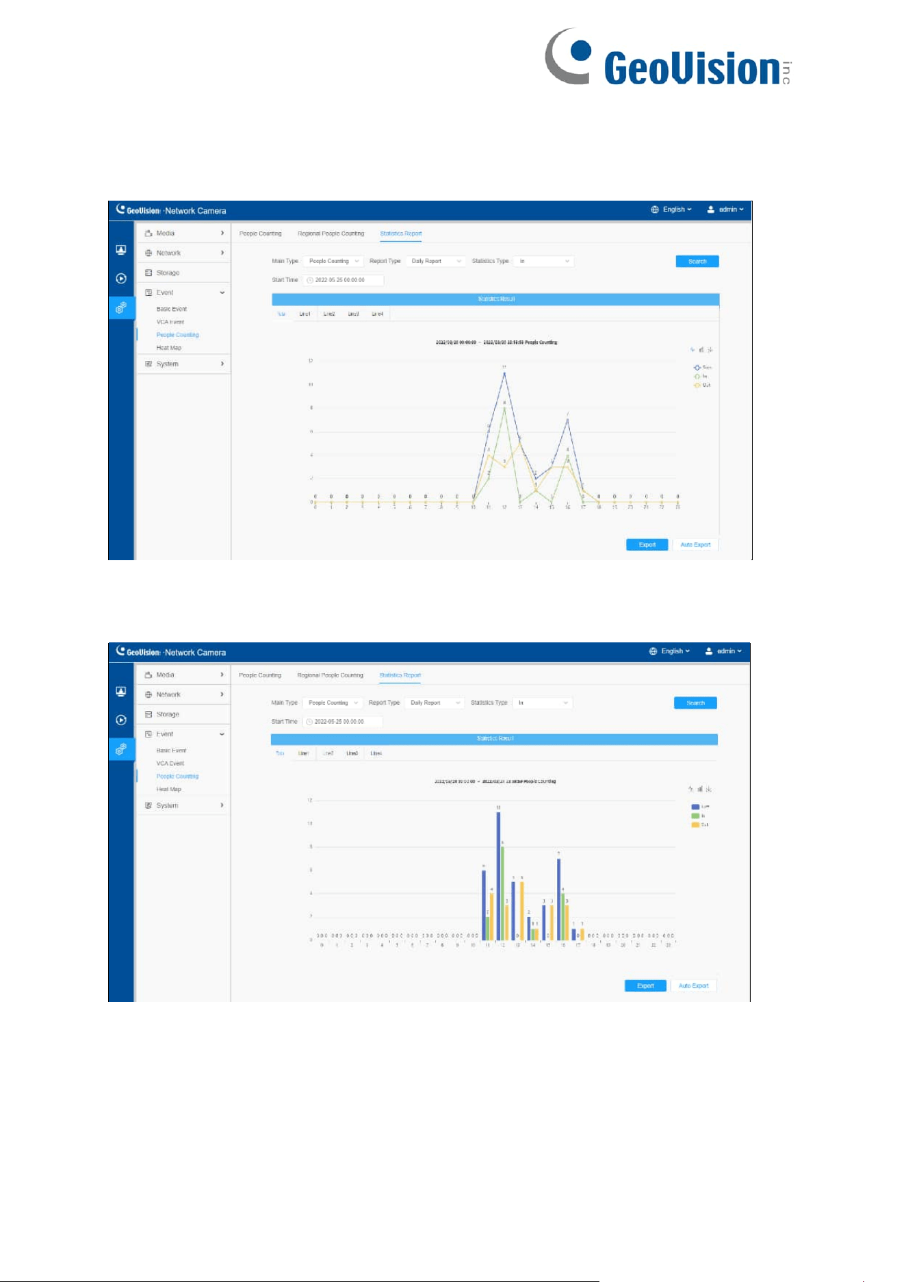
127
People Counting-Statistics Report (Line Chart)
People Counting-Statistics Report (Bar Chart)
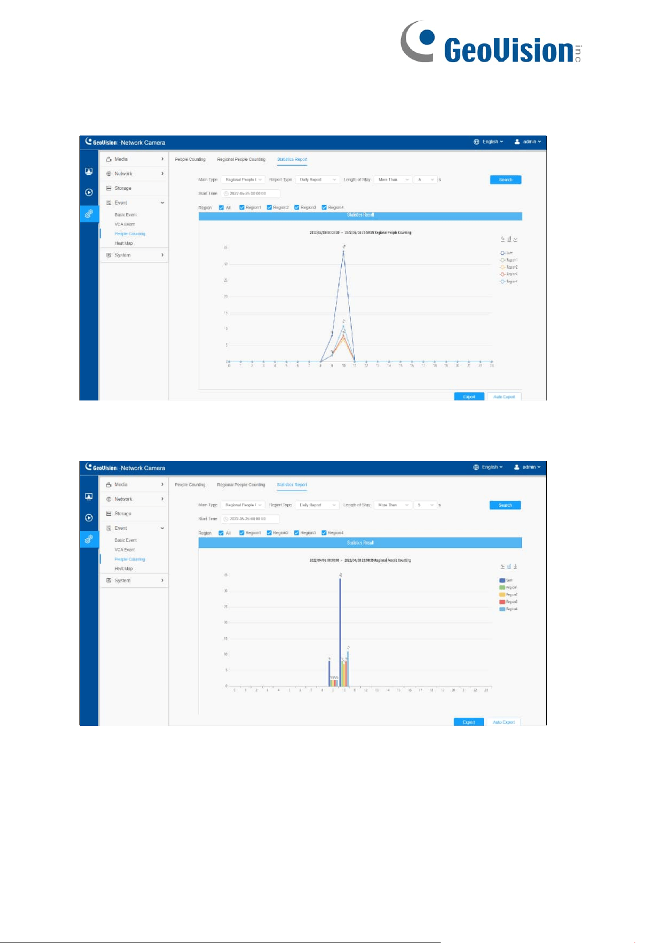
128
Regional People Counting-Statistics Report (Line Chart)
Regional People Counting-Statistics Report (Bar Chart)
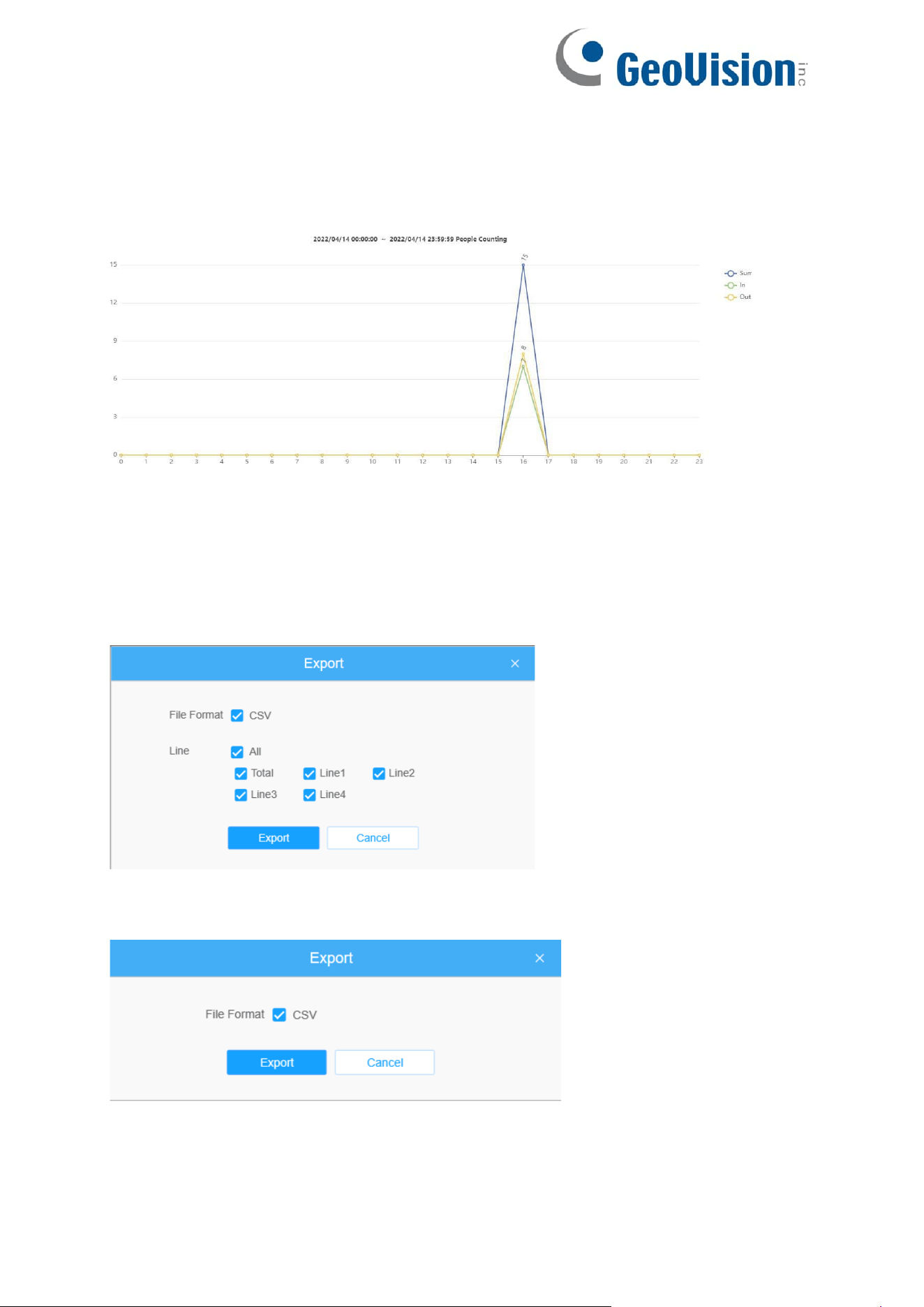
129
Step 6: Click "Download" button to download the screenshot of the statistical report
chart.
Step 7: Click "Export" button to pop up the Export window as shown below, and you can
choose File Format to export the report to local. For people counting Statistics Report,
you can check the check box to export the report of different lines as needed.
People Counting-Export
Regional People Counting-Export
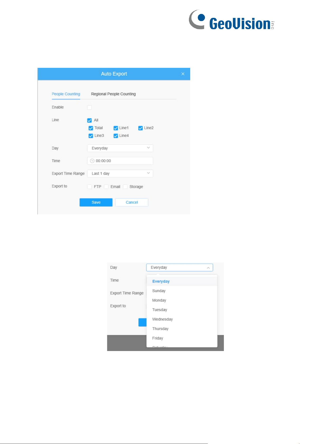
130
Step 8: Click "Auto Export" button to pop up the Statistics Report Settings as shown
below.
• Check the check box to enable the auto export of people counting, then
select the lines as needed.
• Set Day. User can choose Everyday to export daily reports, while choosing
others to export reports on a specific day of the week;
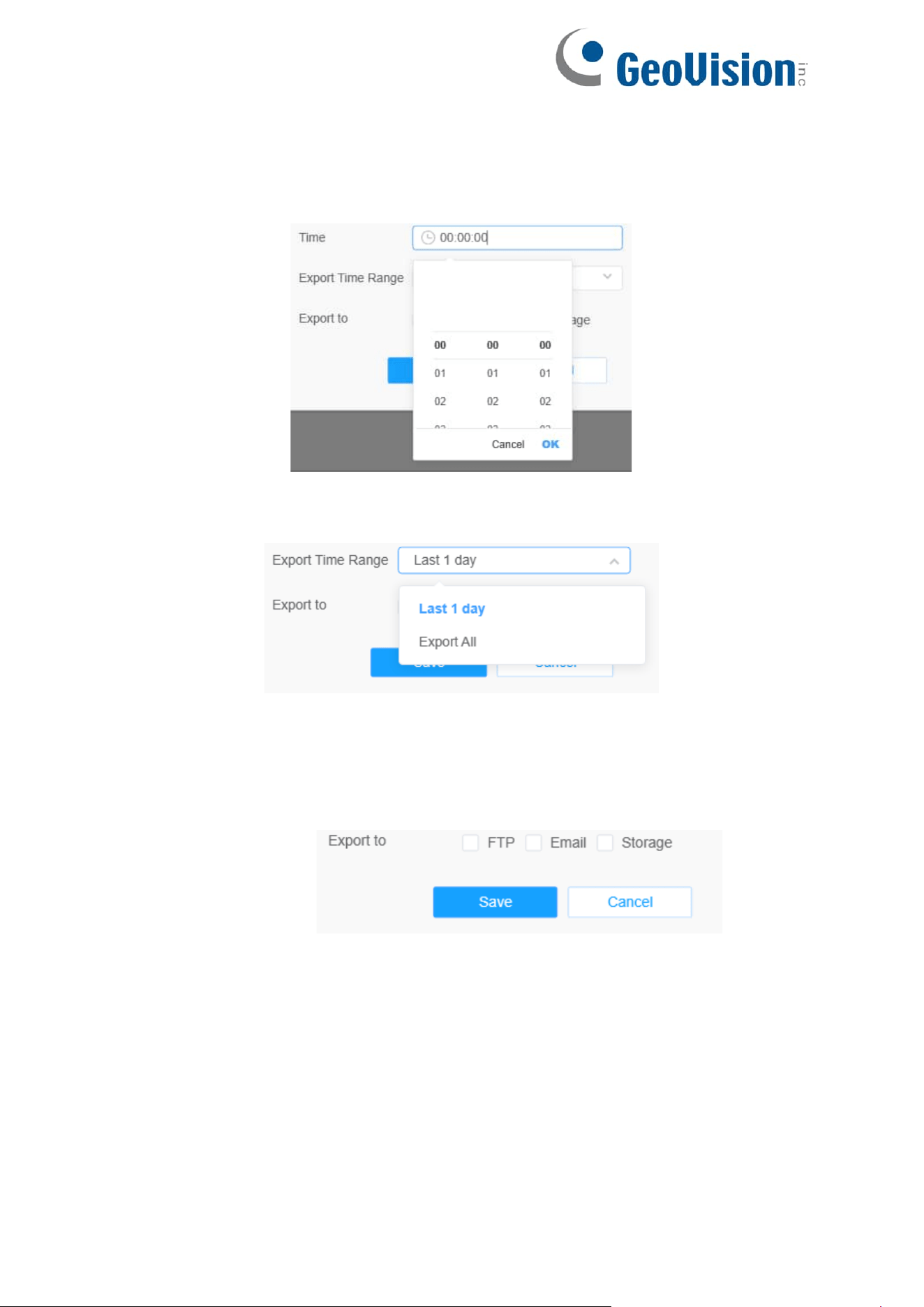
131
• Set Time. User can choose the time of day to export the Statistics Report
automatically, click the calendar icon to pop up the following Quick Selection;
• Set Export Time Range;
• Set the destination path of the automatically exported report. The report can be
exported to FTP/ Email/Storage automatically as the form of an Excel
spreadsheet according to the day, time and export time range you set. Then click
“Save”.
Note: If the current Statistics Report is generated, it will be saved as a csv form.
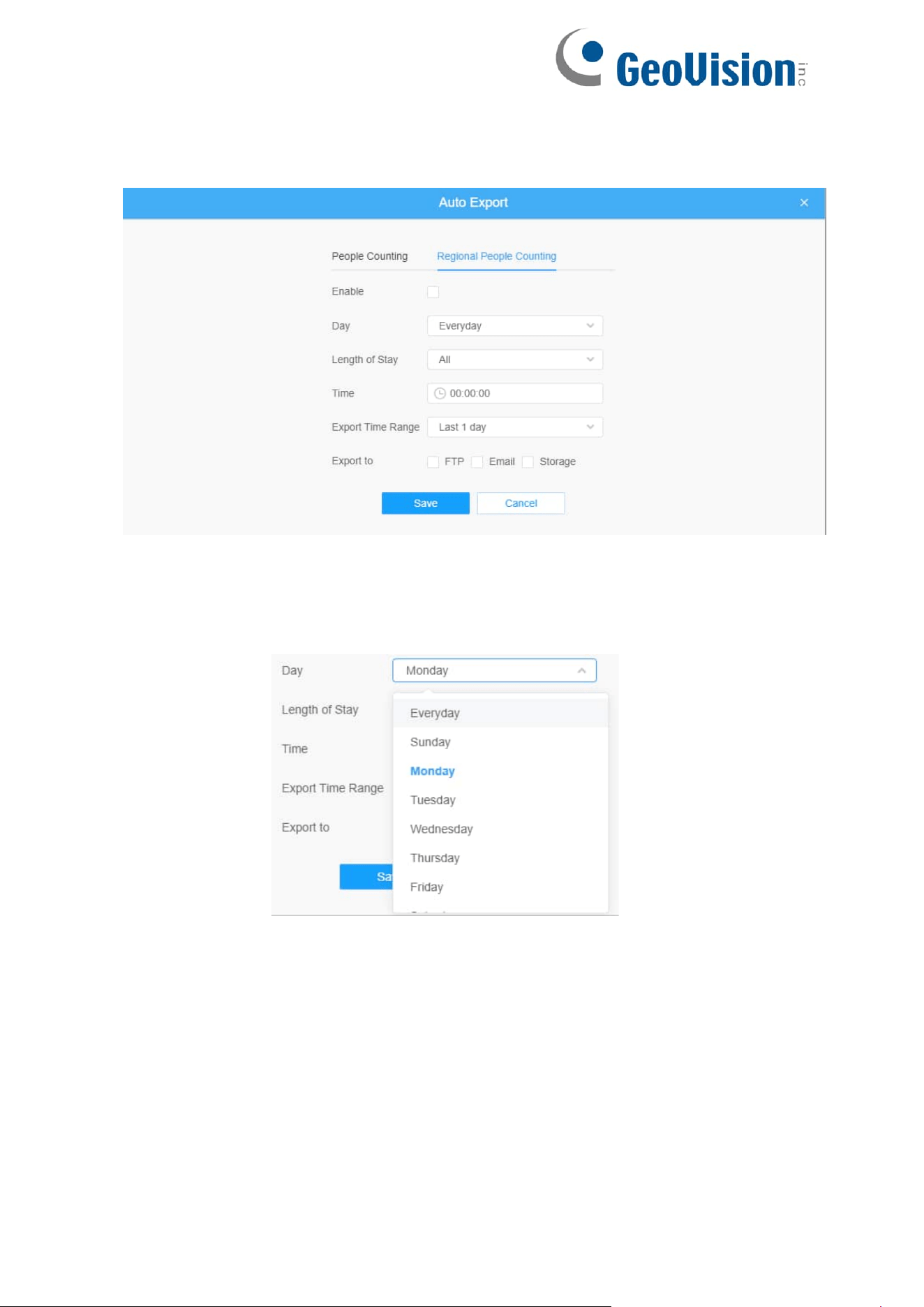
132
Regional People Counting-Auto Export
•
Check the check box to enable the auto export of regional people counting.
• Set Day. User can choose Everyday to export daily reports, while choosing
others to export reports on a specific day of the week;
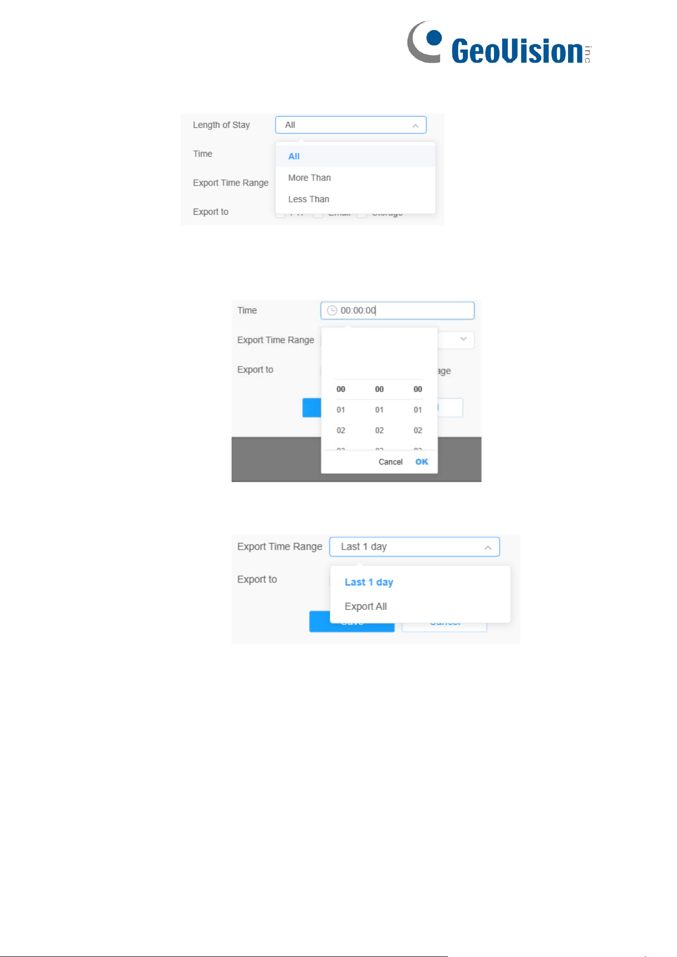
133
•
Set Length of Stay.
• Set Time. User can choose the time of day to export the Statistics Report
automatically, click the calendar icon to pop up the following Quick Selection;
• Set Export Time Range;

134
• Set the destination path of the automatically exported report. The report can be
exported to FTP/ Email/Storage automatically as the form of an Excel
spreadsheet according to the day, time and export time range you set. Then click
“Save”.
Note: If the current Statistics Report is generated, it will be saved as a csv form.
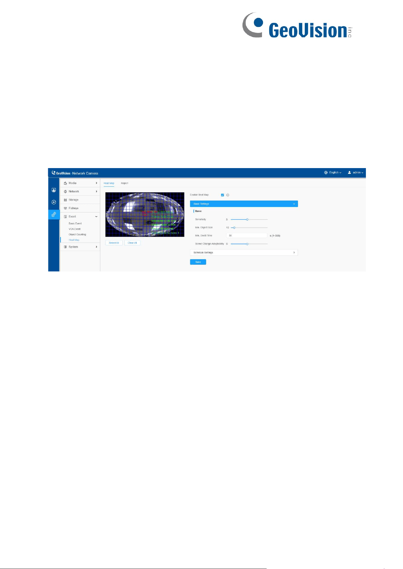
135
8.4.4 Heat Map
Heat Map function can analyze customers movement to reveal insights for better
business management with the intuitive and accurate statistical analysis results in
time or space pattern as needed.
8.4.4.1 Heat Map
Note:
•
Only allowed to view reports within 7 days without a SD card or NAS.
Step 1: Enable Heat Map function.
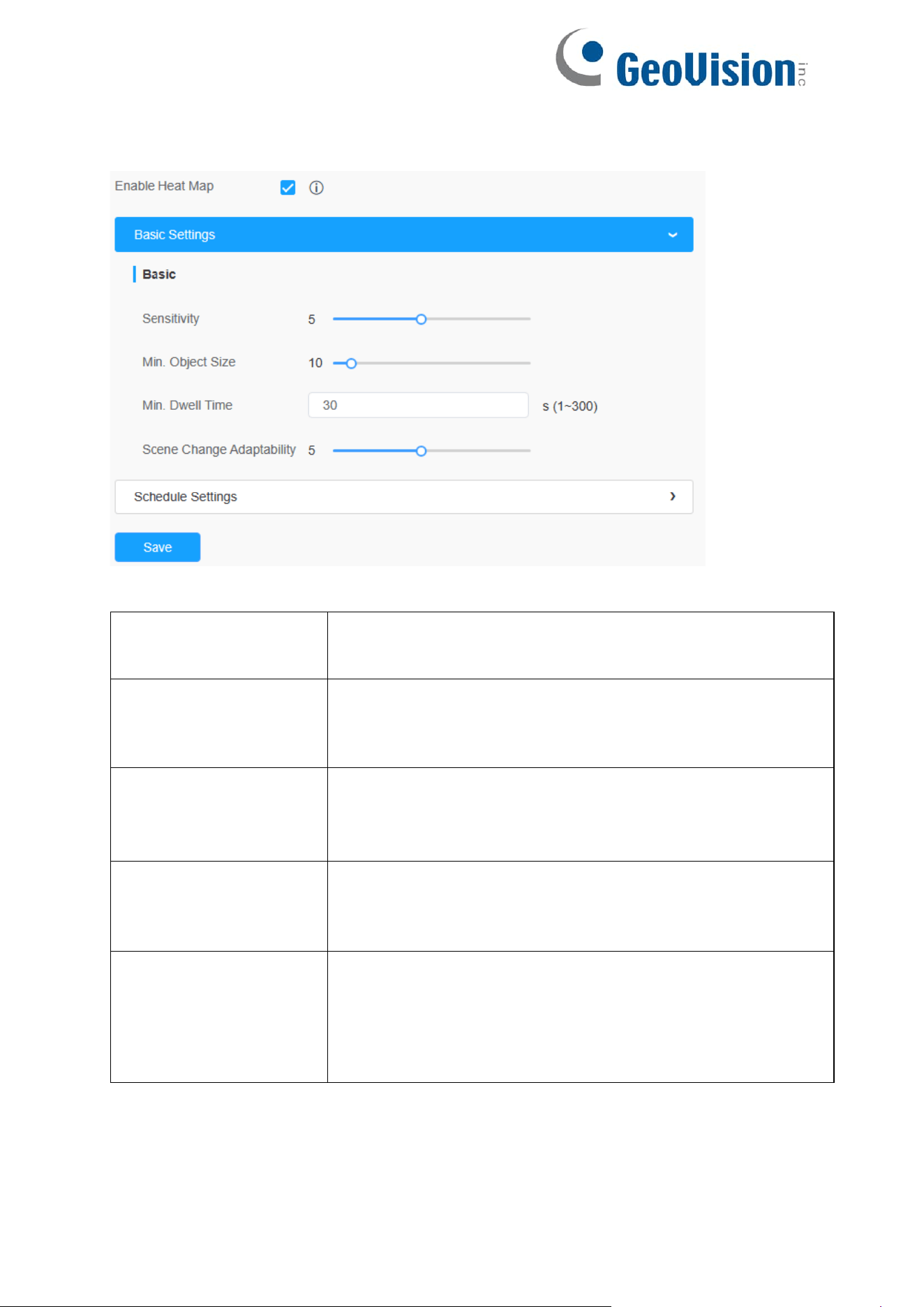
136
[Basic Settings]
Table 57. Description of the buttons
Parameters
Function Introduction
Sensitivity
Level 1~10 is available, the default level is 5. The higher
the sensitivity, the easier it is for moving objects to be
recorded in the results.
Min. Object Size
Set the minimum object size from 1 to 100, the default value
is 10. Objects smaller than this value will not be recorded in
the result.
Min. Dwell Time
Set the minimum dwell time from 1 to 300, the default value
is 30. If the object stays in the area longer than the set
"Minimum Dwell Time", it will not be recorded in the result.
Scene Change
Adaptability
Level 1~10 is available, the default level is 5. Scene
Change Adaptability indicates the camera's adaptability to
scene changes, which can increase the accuracy of
detection. The camera better adapts to faster changing
scenes if the value is higher.

137
Step 2: Set Heat Map Region. Draw the screen to set the detection area. You can
click “Select All” button to select all areas, or "Clear All" button to remove the current
drawn area.
[Schedule Settings]
Step 3: Schedule Settings.
Note: This part is the same as the regular schedule settings. You can refer to
8.4.2.1 Region Entrance.
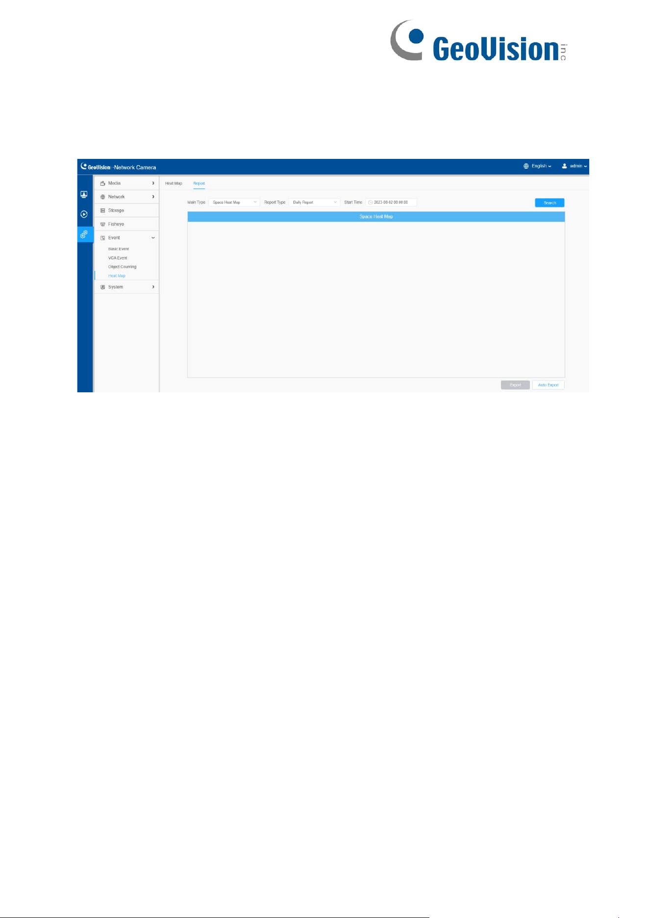
138
8.4.4.2 Report
The heat map results will be displayed on this interface.
Step 1: Select Main Heat Map Type.
[Space Heat Map]: Space Heat Map will be presented as a picture with different
colors. Different colors represent different heat values. Red represents the highest
and blue represents the lowest.
[Time Heat Map]: Time heat map will be presented as a line chart to show the heat at
different times.
Step 2: Select Report Type including Daily Report, Weekly Report, Monthly Report
and Annual Report.
Step 3: Select Start Time, then click the "Search" button, the camera will automatically
count the data for the day/ week/ month/ year (based on the report type selected by the
user) from the start time and generate the corresponding report as shown below.
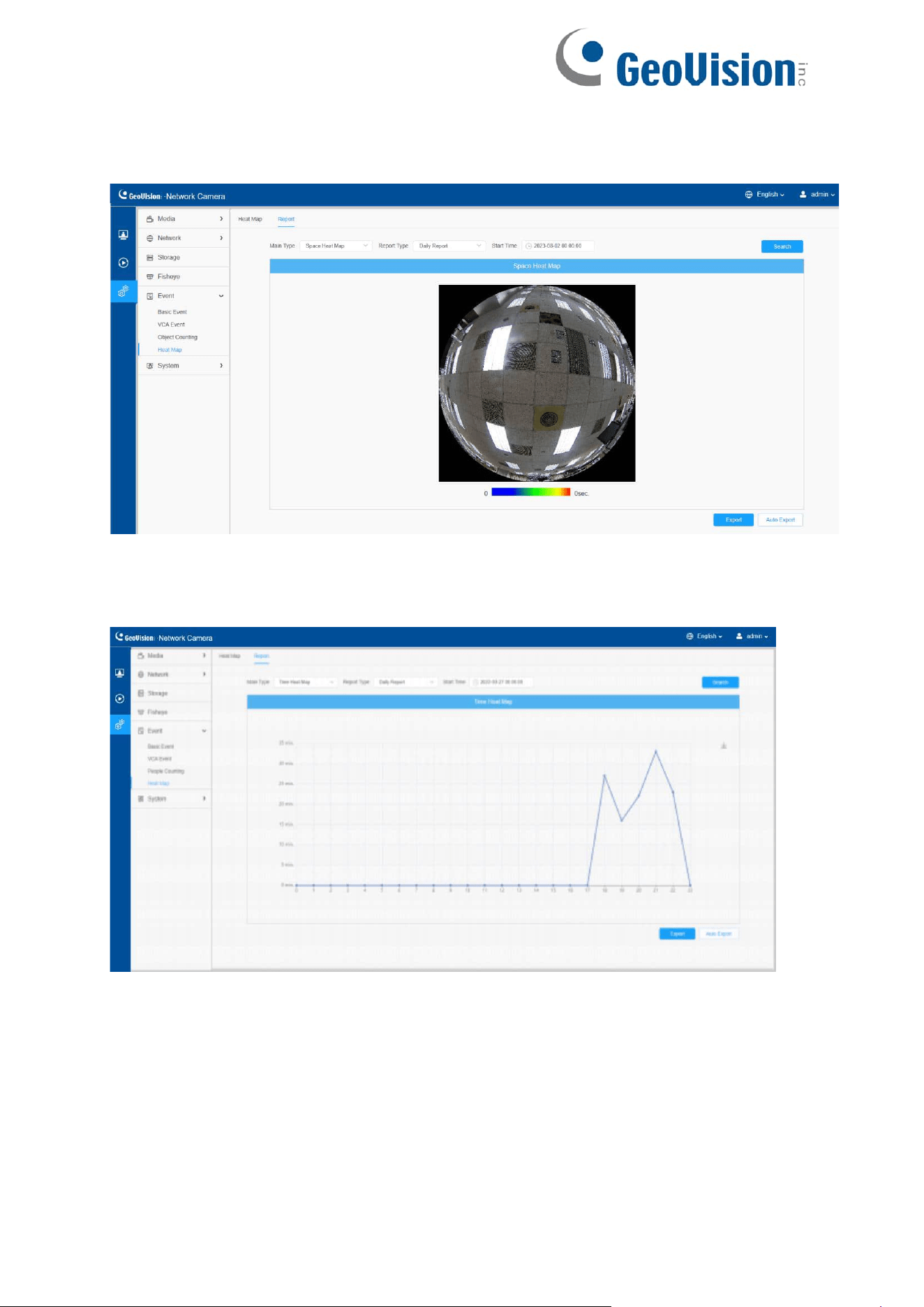
139
Space Heat Map
Time Heat Map
Step 4: Click the "Report Export" button to export the report to local.
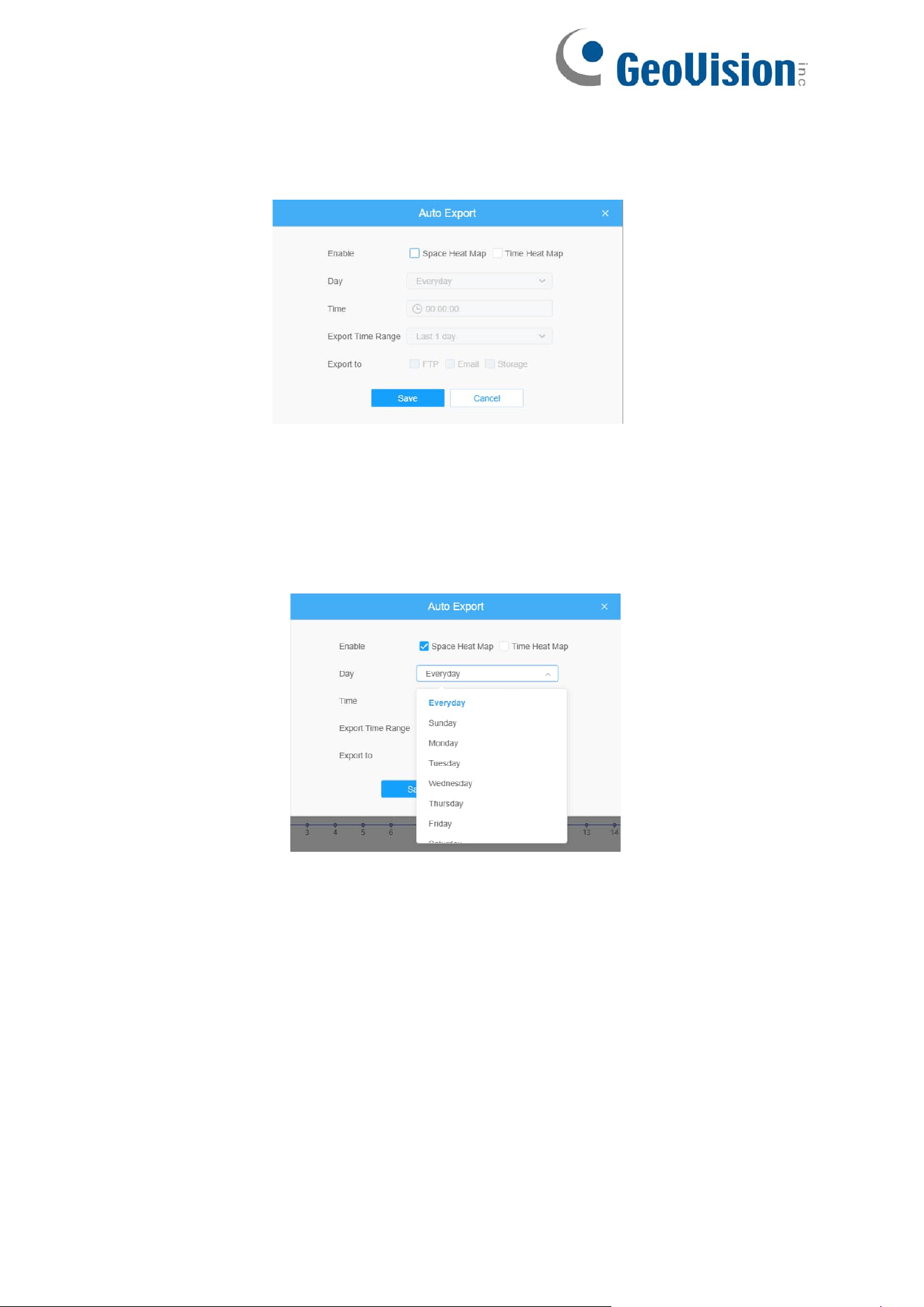
140
Step 5: Click the "Auto Export" button to pop up the Heat Map Report Settings as
shown below.
Set Export Type. User can check Space Heat Map or Time Heat Map or both.
When either Space Heat Map or Time Heat Map is checked, the gray item
becomes editable as shown below;
Set Day. User can choose Everyday to export daily reports, while choosing
others to export reports on a specific day of the week;
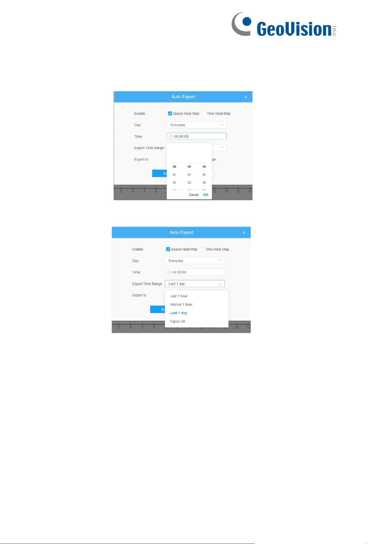
141
• Set Time. User can choose the time of day to export the heat map
automatically, click the calendar icon to pop up the following Quick
Selection;
• Set Export Time Range.
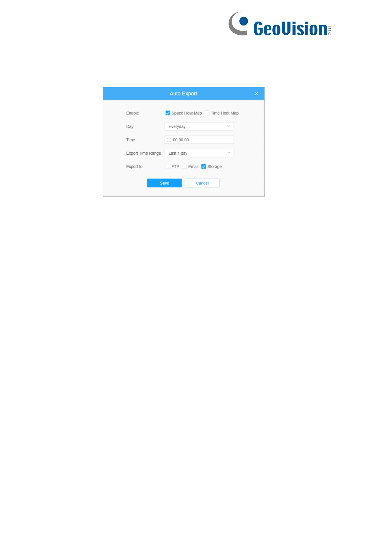
142
Set the destination path of the automatically exported report. The report can be
exported to FTP/ Email/Storage automatically as the form of an Excel
spreadsheet or a picture according to the day, time and export time range you set.
Then click “Save”.
If the current Space Heat Map is generated, it will be saved as a png image. If the
current Time Heat Map is generated, it will be saved as a csv form.
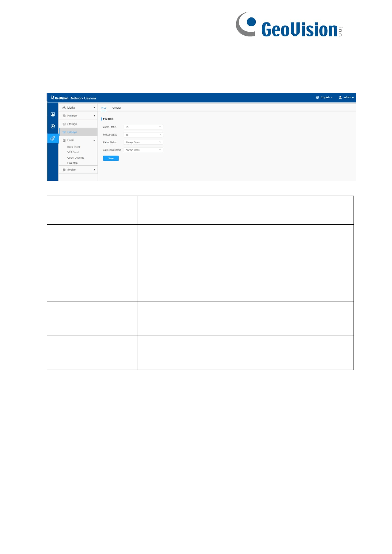
143
8.5 Fisheye
[PTZ]
Table 58. Description of the buttons
Parameters
Function Introduction
Zoom Status
Support to set display time of Zoom Status OSD.
2 seconds/5 seconds/10 seconds/Always Open/Always Close
are available.
Preset Status
Support to set display time of Preset Status OSD.
2 seconds/5 seconds/10 seconds/Always Open/Always Close
are available.
Patrol Status
Support to set display time of Patrol Status OSD.
Always Open/Always Close are available.
Auto Scan Status
Support to set display time of Auto Scan Status OSD.
Always Open/Always Close are available.
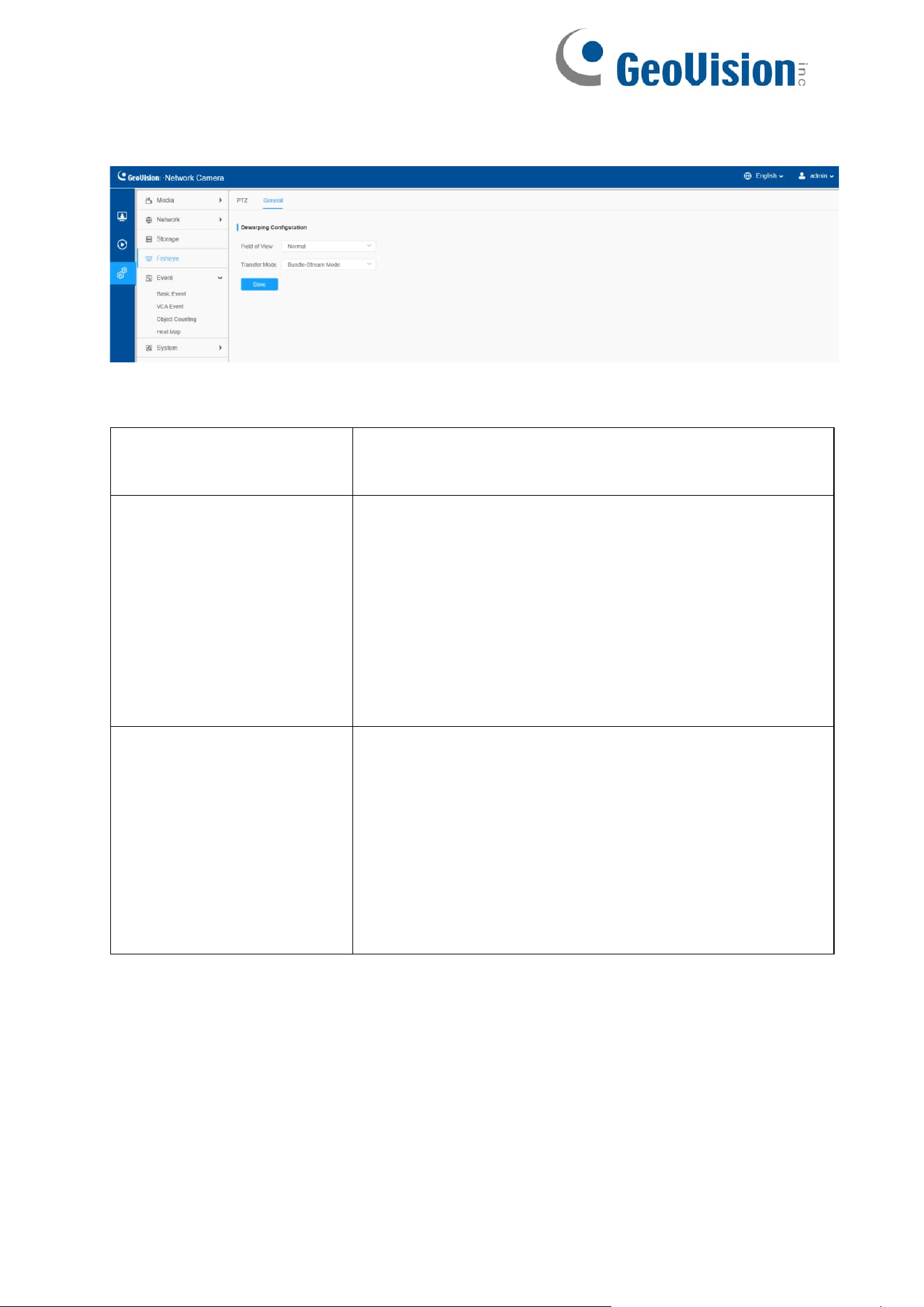
144
[General]
Table 59. Description of the buttons
Parameters
Function Introduction
Field of View
Support optional Field of View on fisheye camera.
Normal: With this option enabled, all views will maintain
the original viewing angle.
Original View Larger: With this option enabled, the
original view(1O) will have a larger viewing angle, and the
other views will maintain the original viewing angle.
All View Larger: With this option enabled, all views will
have a larger viewing angle.
Transfer Mode
Support to choose Bundle-Stream Mode or Multi-
Channel Mode to meet different needs.
Bundle-Stream Mode: The Bundle-Stream Mode
combines all the channels into one and sends to NVR
or VMS, which is easy for compatibility.
Multi-Channel Mode: The Multi-Channel Mode sends all
the original channels to NVR or VMS, so the channels
can be modified separately.
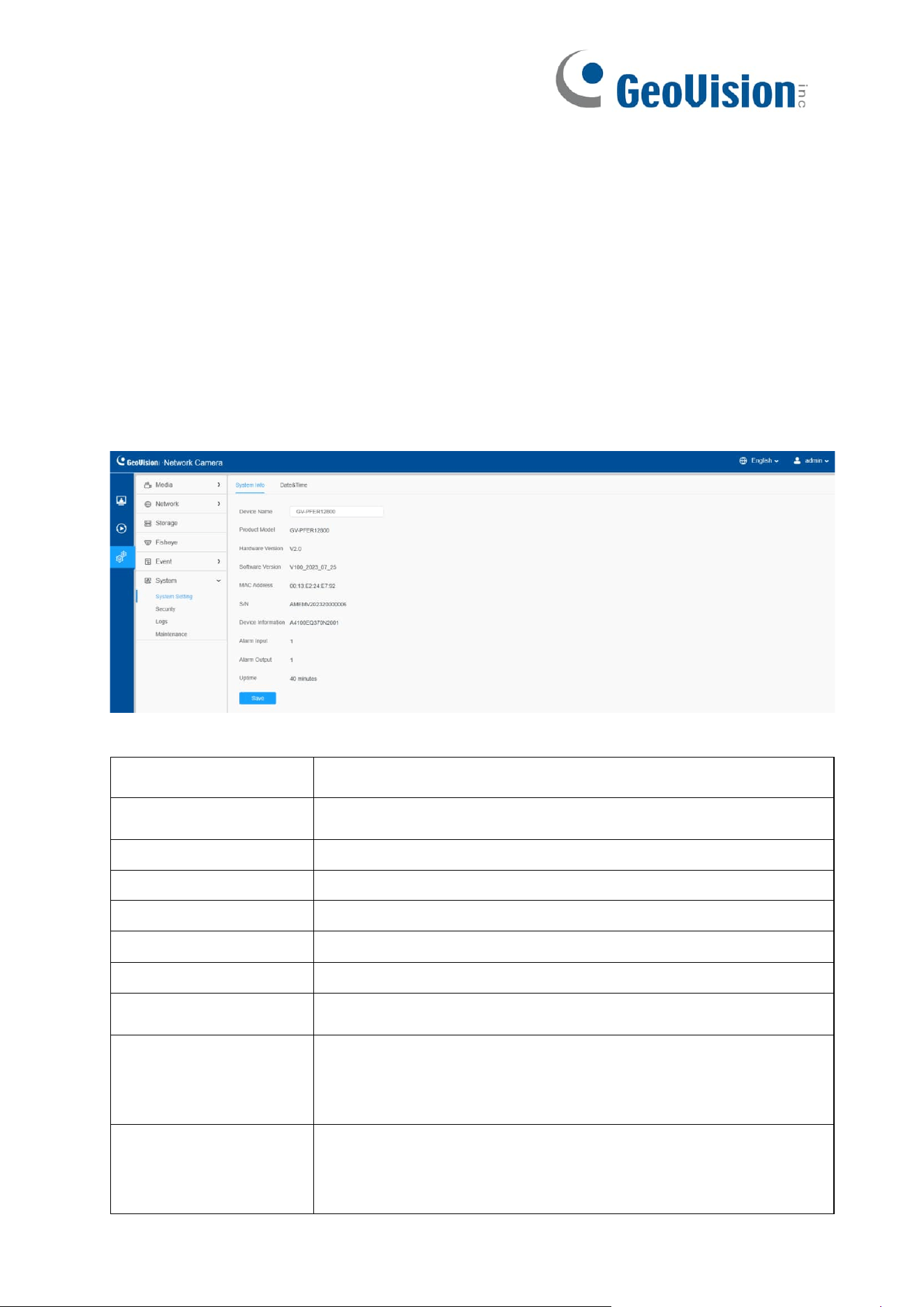
145
8.6 System
Here you can configure System Setting, Security, Logs and Maintenance.
8.6.1 System Setting
Here you can check System information and Date & Time.
8.6.1.1 System info
All information about the hardware and software of the camera can be checked on this
page.
Table 60. Description of the buttons
Parameters
Function Introduction
Device Name
The device name can be customized. It will be seen in file
names of video files.
Product Model
The product model of the camera.
Hardware Version
The hardware version of the camera.
Software Version
The software version of the camera can be upgraded.
MAC Address
Media Access Control address.
S/N
Stock Number.
Device Information
The device information, including information about alarm I/O
and clipper chip.
Alarm Input
The number of Alarm Input interface.
Note: The Alarm Input will appear only when the camera has
alarm input/
output interface.
Alarm Output
The number of Alarm Output interface.
Note: The Alarm Output will appear only when the camera
has alarm input/
output interface.
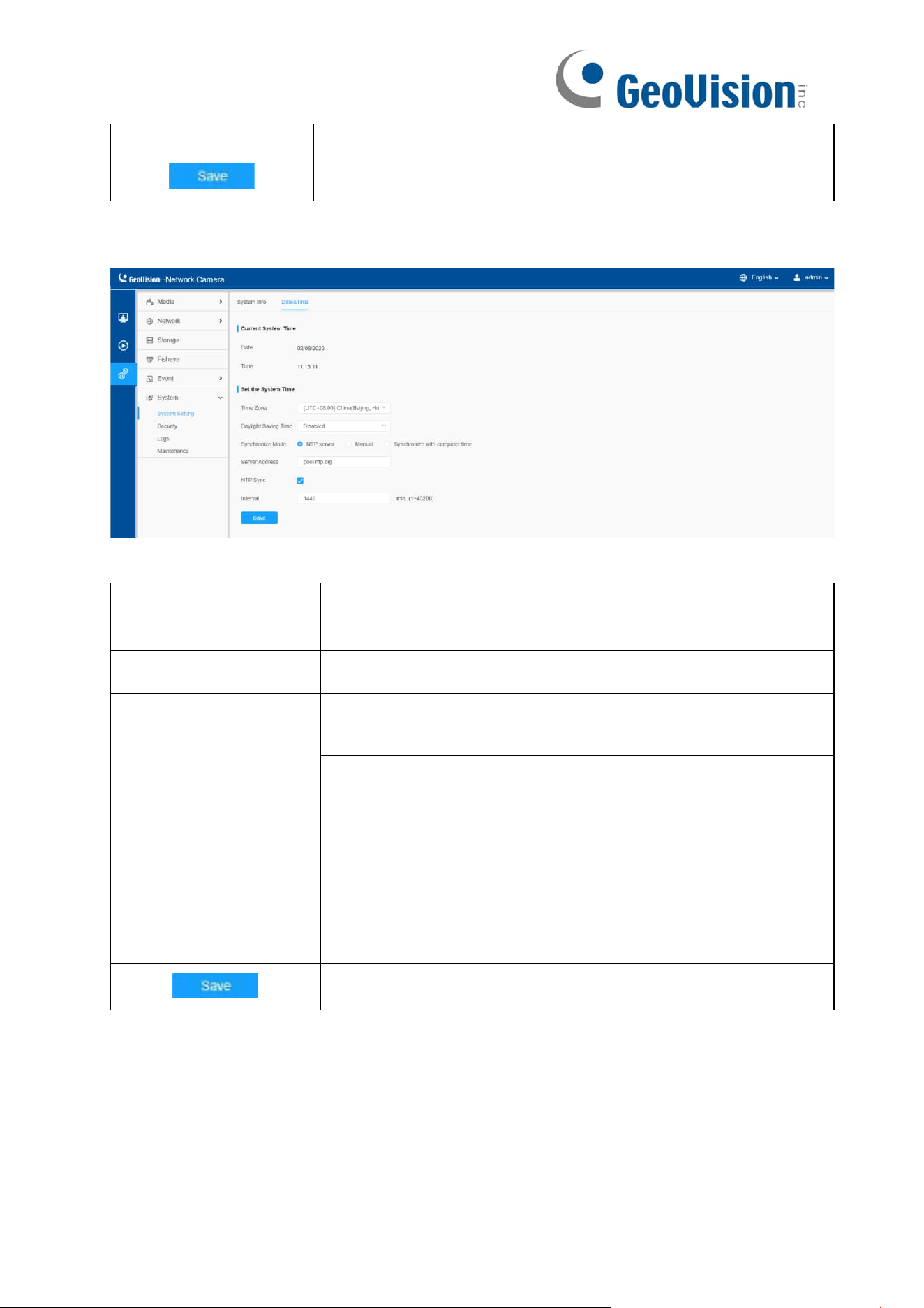
146
Uptime
The elapsed time since the last restarted of the device.
Save the configuration.
8.6.1.2 Date & Time
Table 61. Description of the buttons
Parameters
Function Introduction
Current System
Time
Current date & time of the system.
Set the System Time
Time Zone: Choose a time zone for your location.
Daylight Saving time: Enable the daylight-saving time.
Synchronize Mode: NTP server, Manual and Synchronize
with computer time are optional.
NTP server: Input the address of NTP server.
NTP Sync: Regularly update your time according to the
interval time.
Manual: Set the system time manually.
Synchronize with computer time: Synchronize the time with
your computer.
Save the configuration.
8.6.2 Security
Here you can configure User, Access List, Security Service, Watermark, etc.
8.6.2.1 User
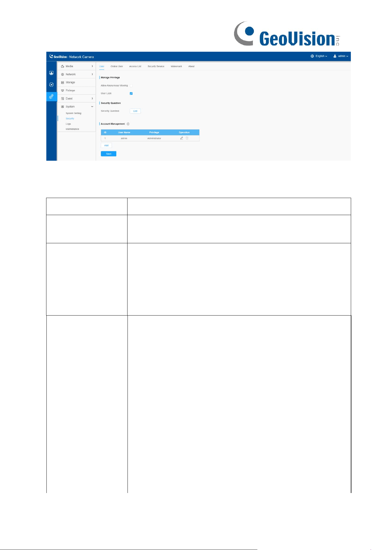
147
Table 62. Description of the buttons
Parameters
Function Introduction
Manage Privilege
Allow anonymous viewing: Check the checkbox to enable
visit from whom doesn’t have account of the device.
Security Question
Click “Edit” button to set three security questions for your
camera. In case that you forget the password, you can click
“Forget Password” button on login page to reset the password
by answering three security questions correctly.
There are twelve default questions below, you can also
customize the security questions.
Account Management
Click “Add” button, it will display Account Management page.
You can add an account to the camera by entering Admin
Password, User Level, User Name, New Password, Confirm,
and edit user privilege by clicking. The added account will be
displayed in the account list.
Admin Password: You can add an account only after you
enter the correct admin password.
User Level: Set the privilege for the account.
User Name: Input user name for creating an account.
New Password: Input password for the account.
Confirm: Confirm the password.
You can edit and delete the account in the account list under
the admin account. For the default admin account, you can
only change the password, and it cannot be deleted.
Note:

148
•
Support up to 20 users, including a default user and 19
custom added users.
•
The operator privilege is all checked by default.
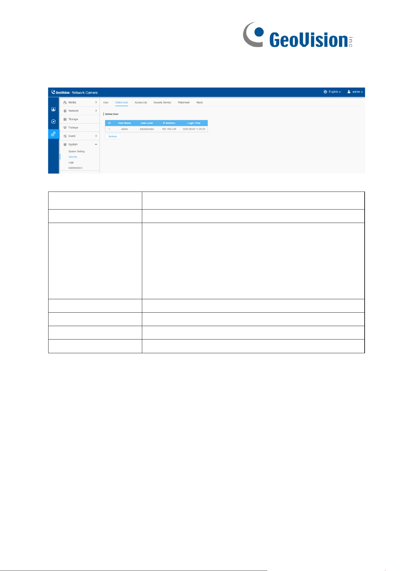
149
8.6.2.2 Online User
Here real-time status of user logging in camera will be shown.
Table 63. Description of the buttons
Parameters
Function Introduction
Refresh
Click to get latest status of user accessing to camera.
ID
Record serial number of user logging in camera.
Note:
•
There are at most 30 records shown at the list.
• There is only one record if the same user logging on
camera by the same IP address.
User Name
Name of user logging in camera.
User Level
Level of user logging in camera.
IP Address
Device IP address where user logging in camera web located.
Login Time
Camera system time of user logging in camera.
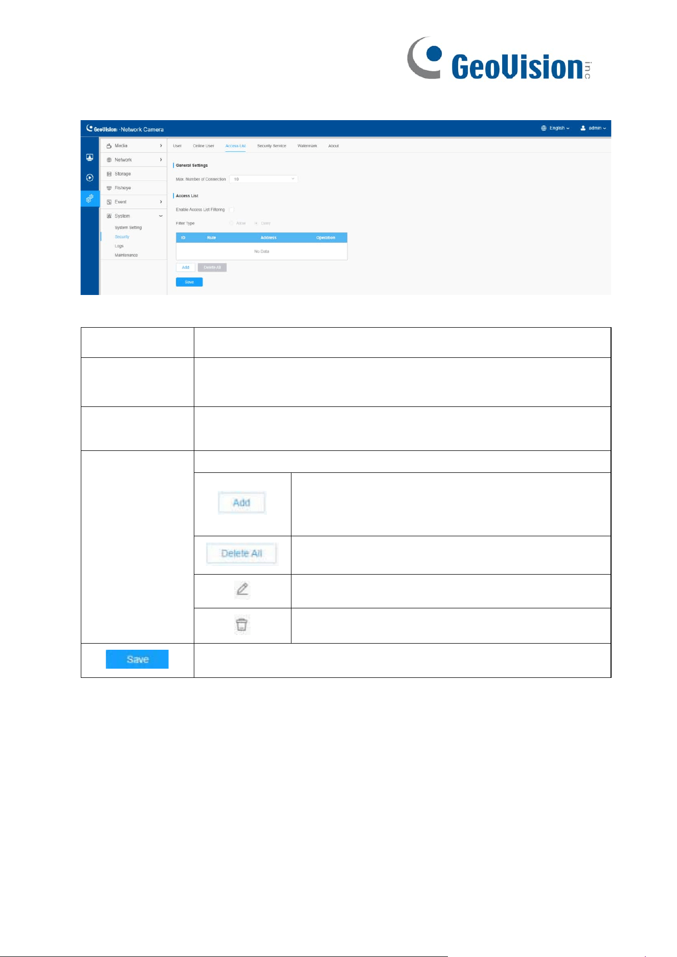
150
8.6.2.3 Access List
Table 64. Description of the buttons
Parameters
Function Introduction
General Settings
Max. Number of Connection: Select the maximum number of
concurrent streaming. Options include No Limit, 1~10.
Access List
Enable Access List Filtering: Able to access or restrict access for
some IP address.
Access List
Filter type: Allow or deny access.
Rule: Single, Network and Range are available.
IP address: Input the address to get the access to
the device.
Delete all the access list.
Edit the selected IP on access list.
Delete the selected IP on access list.
Save the configuration.
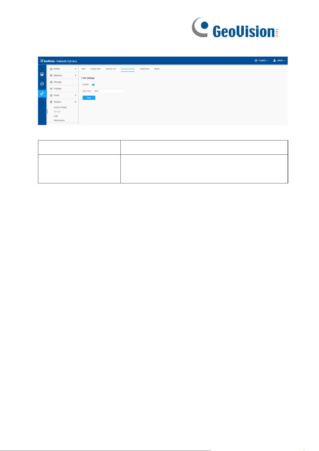
151
8.6.2.4 Security Service
Table 65. Description of the buttons
Parameters
Function Introduction
SSH Settings
Secure Shell (SSH) has many functions: it can
replace Telnet and also provides a secure channel
for FTP, POP, even for PPP.
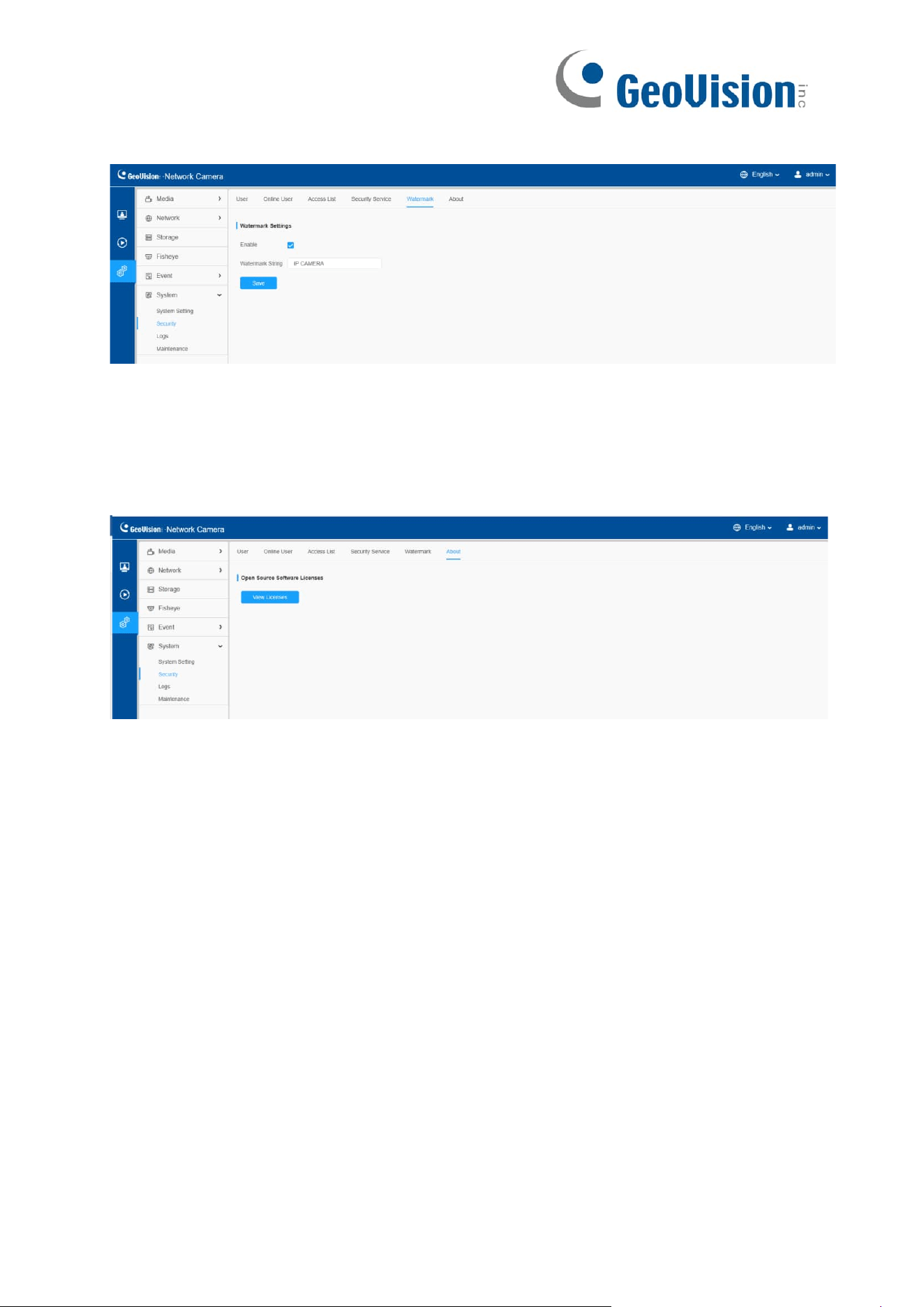
152
8.6.2.5 Watermark
Watermarking is an effective method to protect information security, realizing anti-
counterfeiting traceability and copyright protection. Watermark function is supported to
ensure information security.
8.6.2.6 About
User can view some open-source software licenses about the camera by clicking the
View Licenses button.
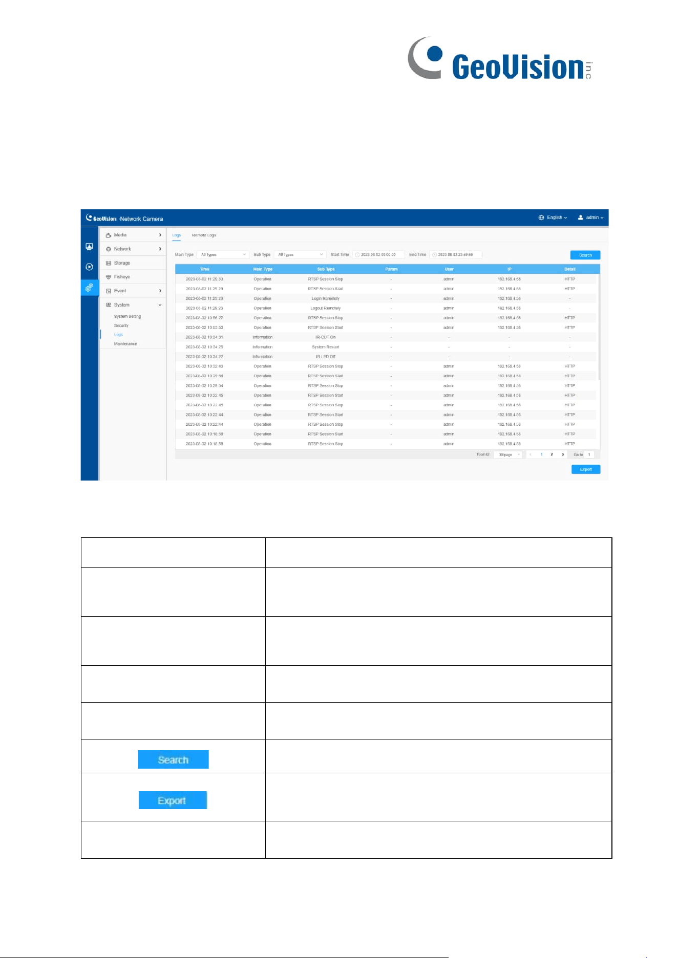
153
8.6.3 Logs
8.6.3.1 Logs
The logs contain the information about the time and IP that has accessed the camera
through web.
Table 66. Description of the buttons
Parameters
Function Introduction
Main Type
There are five main log types: All Type, Event,
Operation, Information, Exception and Smart.
Sub Type
On the premise that main type has been selected,
select the sub type to narrow the range of logs.
Start Time
The time log starts.
End Time
The time log ends.
Search the logs.
Export the logs.
Go to
Input the number of logs’ page.
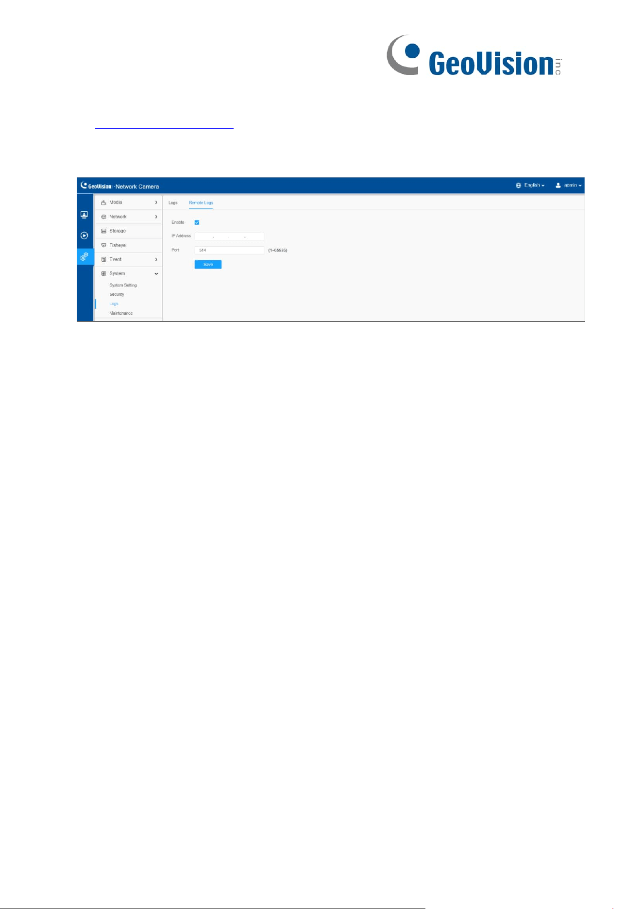
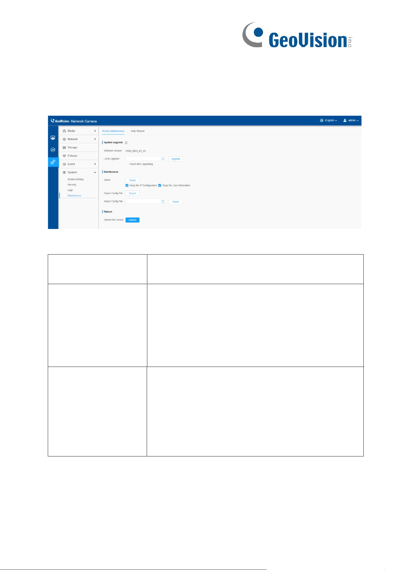
155
8.6.4 Maintenance
Here you can configure System Maintenance and Auto Reboot.
8.6.4.1 System Maintenance
Table 67. Description of the buttons
Parameters
Function Introduction
System Upgrade
Software Version: The software version of the camera.
Local Upgrade: Click the “Browse” button and select the
upgrading file, then click the “Upgrade” button to upgrade.
After the system reboots successfully, the update is done.
You can check “Reset after Upgrading” to reset the
camera after upgrading it.
Maintenance
Reset: Click “Reset” button to reset the camera to factory
default settings.
Keep the IP Configuration: Check this option to keep the
IP configuration when resetting the camera.
Keep the User information: Check this option to keep
the user information when resetting the camera.
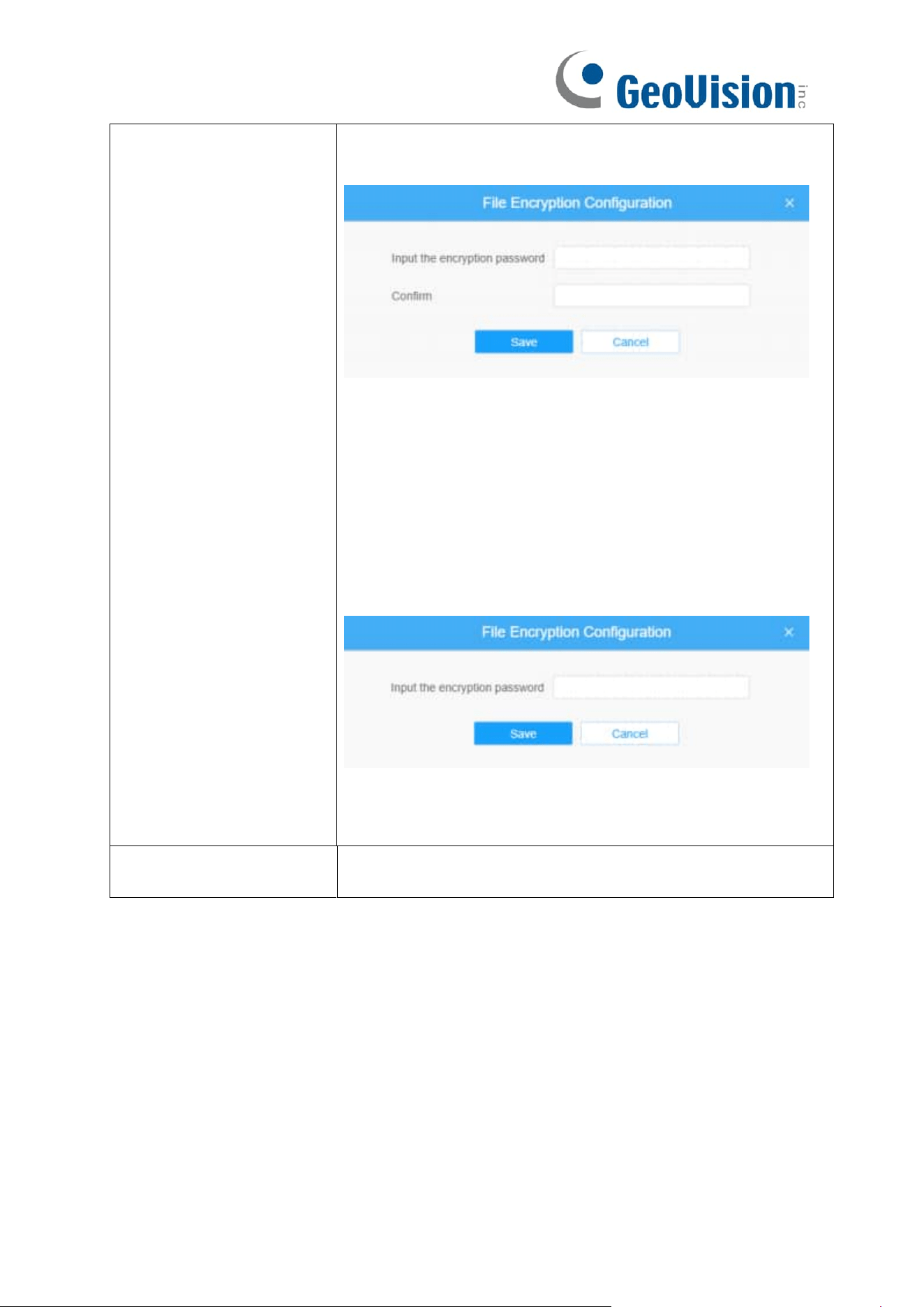
156
Export Config File: Click this button and a window will pop
up as shown below:
You need to enter and confirm password again, then click
save button to export configuration file.
Import Config File: Click this button, then a window will
pop up and you can click "OK" to update the
configuration.
It will pop up a window to prompt "Input the password of
config file”, then enter password and click save button to
import configuration file.
Note:
Export and import the same configuration file. Password
must be the same.
Reboot
Click “Reboot” button to restart the device immediately.

157
8.6.4.2 Auto Reboot
Set the date and time to enable Auto Reboot function, the camera will reboot
automatically according to the customized time in case that camera overload after
running a long time.
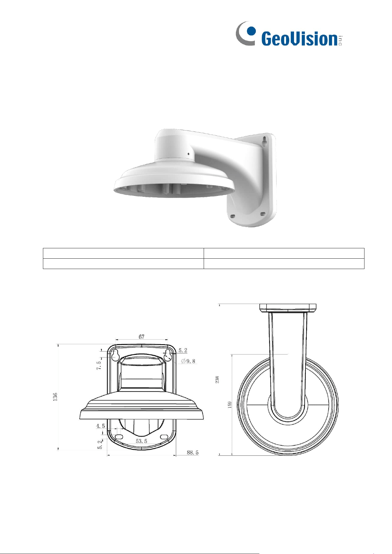
158
Appendix
A. Optional Installation
1. GV-Mount211-7
GV-Mount211-7 Packing List
1. GV-Mount211-7
2. M4 Screw (40 mm) x 4
3. M4 Screw (6 mm) x 4
4. Hex Key
Dimension
Unit: mm
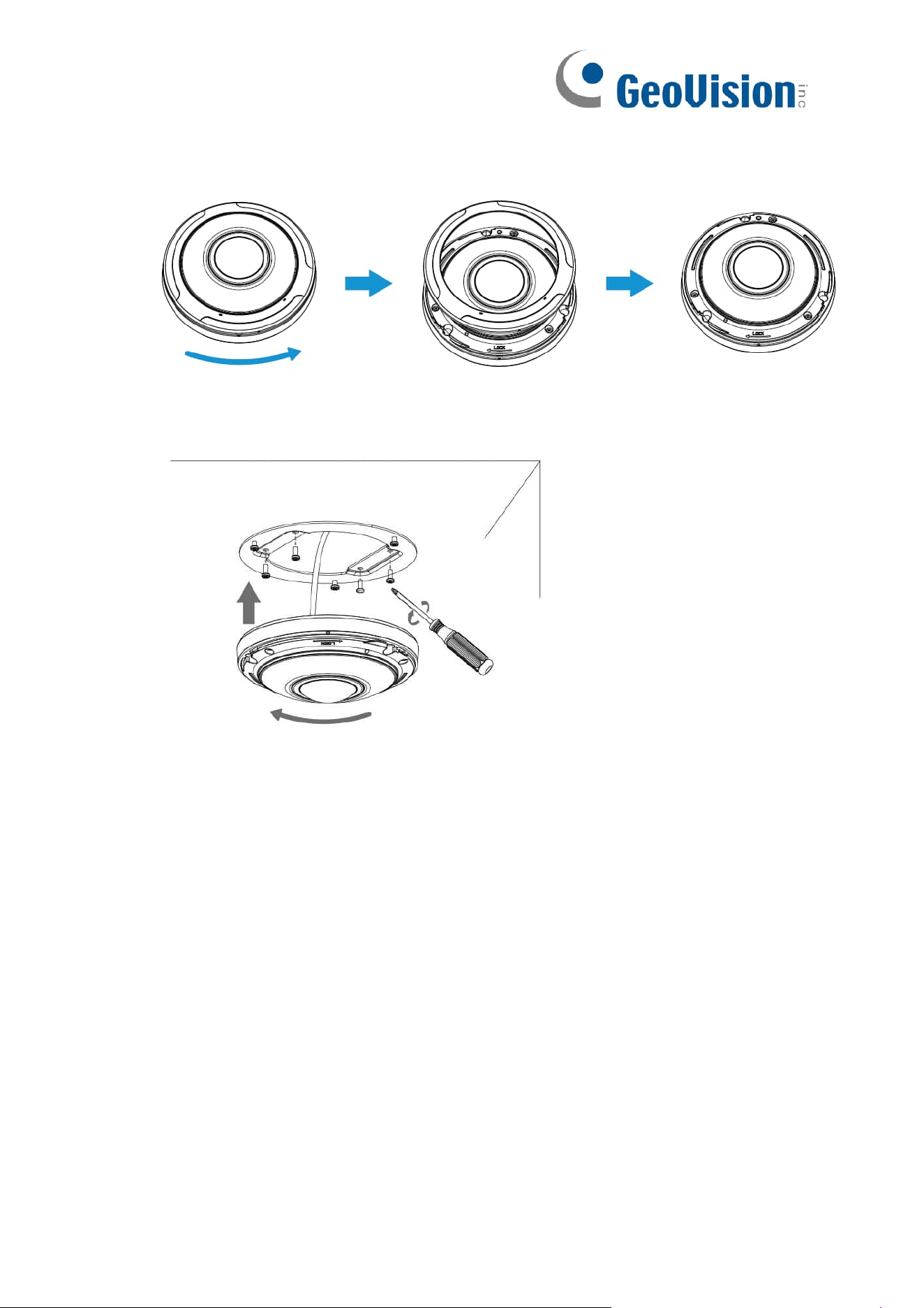
159
Install with Wall Mount Bracket GV-Mount211-7
1. Hold the camera and turn the top cover anticlockwise, then take it off.
2. Remove the base plate from the camera.
3. Fix GV-Mount211-7 on the wall where the camera is intended to be installed.
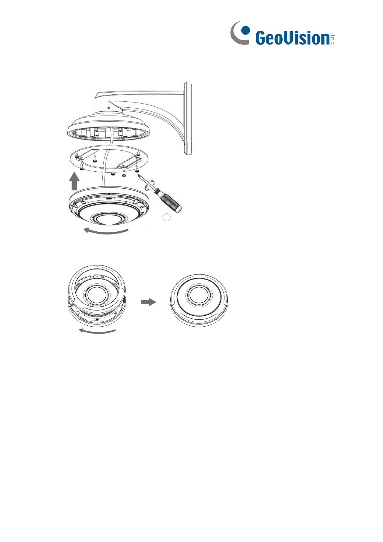
160
4. Secure the base plate onto GV-Mount211-7, thread the cables of the camera, and
fix the camera onto the base plate.
5. Turn the top cover clockwise till the anchor points are aligned.
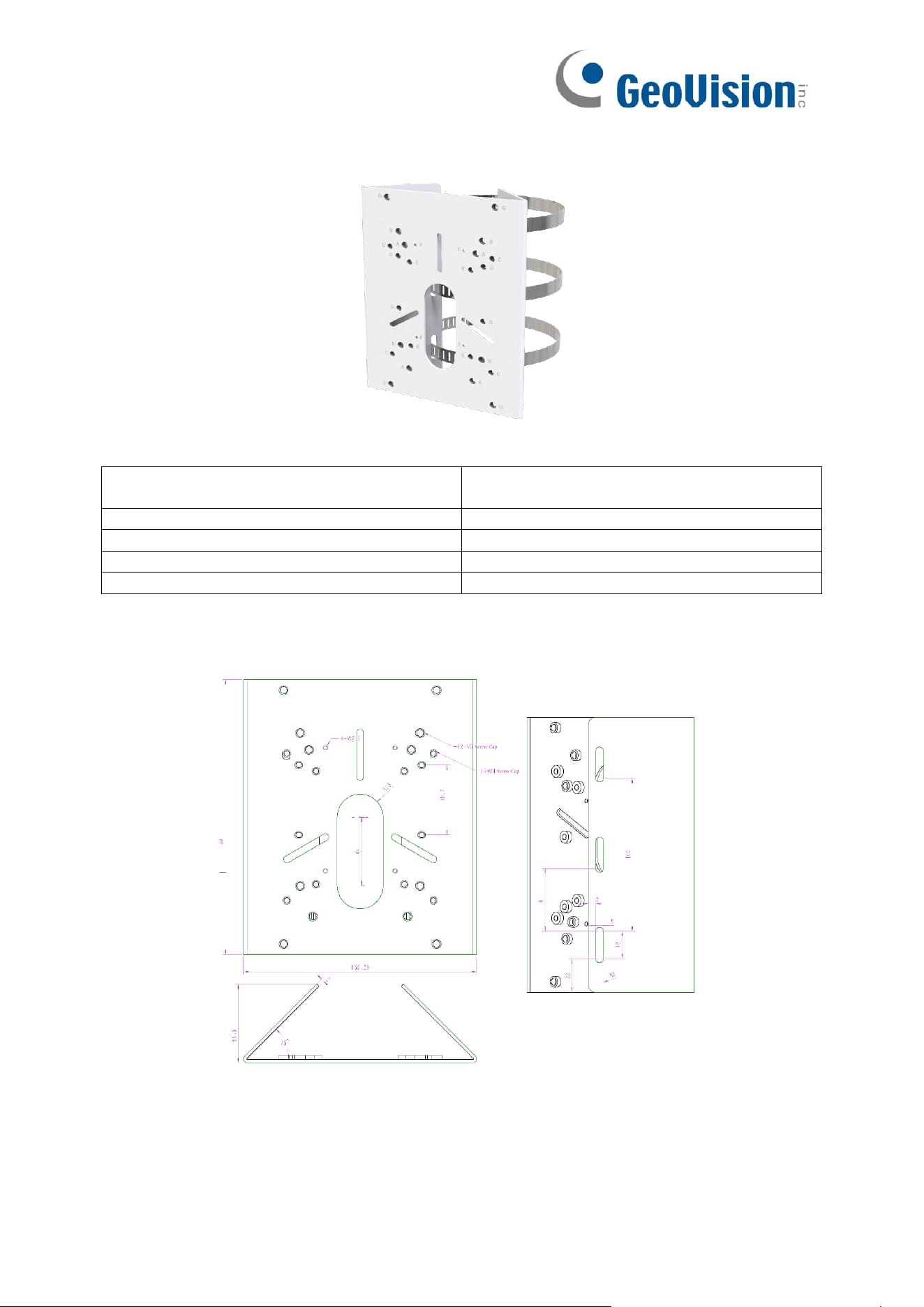
161
2. GV-Mount430
GV-Mount430 Packing List
1. GV-Mount430
2. Steel Strap (Ø 102 ~ 107; 4.1” ~ 5”) x
3
3. Plain Washer (Ø 6 x 18 x 1.5 mm) x 4
4. M4 Plain Washer (10 x 1 mm) x 4
5. M3 Screw (12 mm) x 3
6. M4 Screw (12 mm) x 4
7. M4 Screw (20 mm) x 4
8. M5 Screw (25 mm) x 4
9. M3 Screw Cap x 3
10. M4 Screw Cap x 4
Dimension
Unit: mm
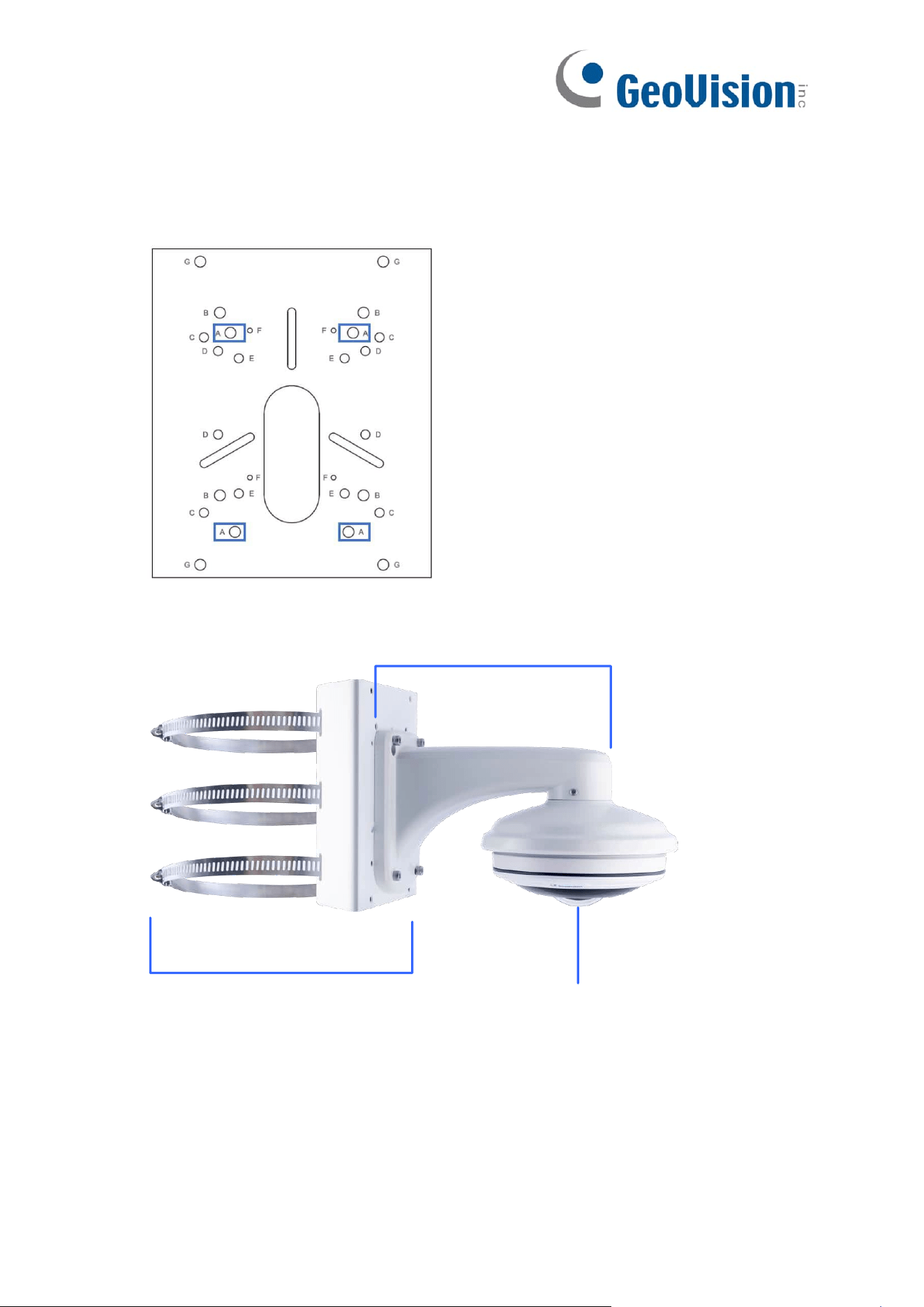
162
Install with Pole Mount Bracket GV-Mount430
Note: It is required to use GV-Mount211-7 with GV-Mount430 to complete pole mounting
of GV-PFER12800.
1. Secure GV-Mount211-7 onto GV-Mount430 according to the holes indicated below.
2. Follow the installation instruction in 1. GV-Mount211-7 to finish the installation of the
camera and GV-Mount211-7.
GV-Mount211-7
GV-Mount430
GV-PFER12800
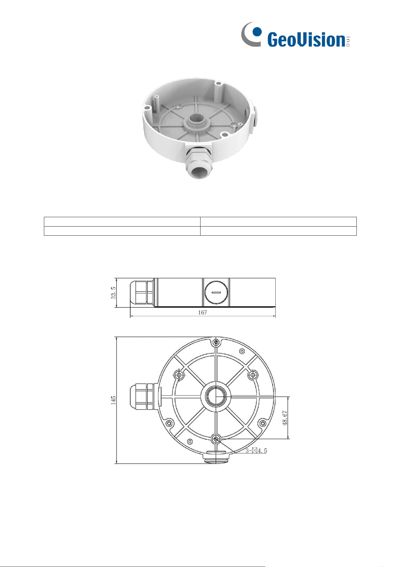
163
3. GV-Mount508
GV-Mount508 Packing List
1. GV-Mount508
2. M4 Screw (30 mm) x 3
3. M4 Screw (8 mm) x 3
4. Drill Template Paster
Dimension
Unit: mm
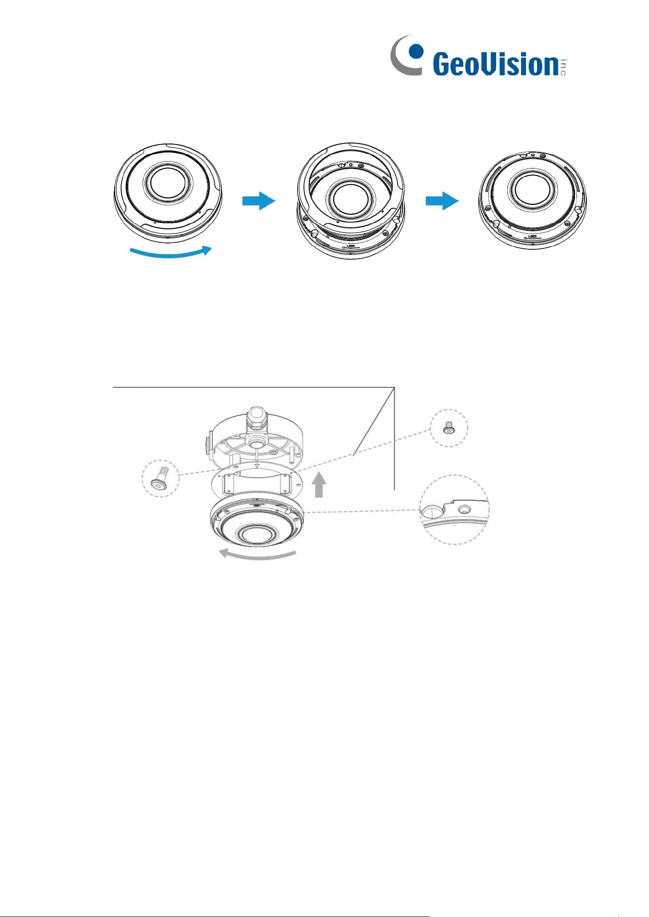
164
Install with Junction Box GV-Mount508
1. Hold the camera and turn the top cover anticlockwise, then take it off.
2. Remove the base plate from the camera.
3. Fix GV-Mount508 in the position where the camera is intended to be installed.
4. Secure the base plate to GV-Mount508. Pay attention that the two marks on the
junction box and the bracket shall be aligned. Then connect the cables and rotate
the camera to GV-Mount508 and secure them.
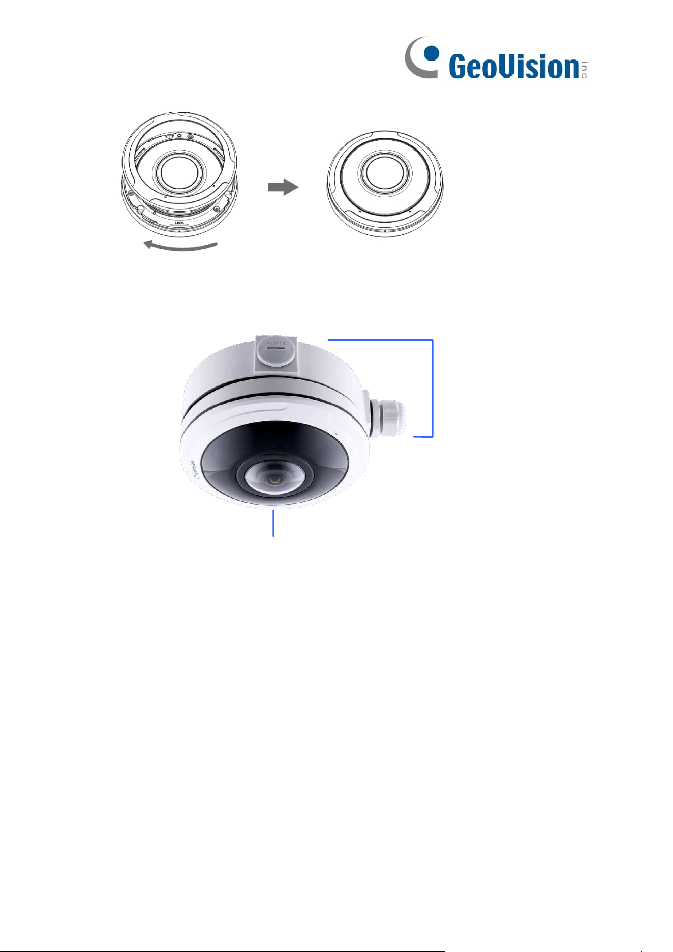
165
5. Turn the top cover clockwise till the anchor points are aligned.
GV-PFER12800 + GV-Mount508
GV-PFER12800
GV-Mount508
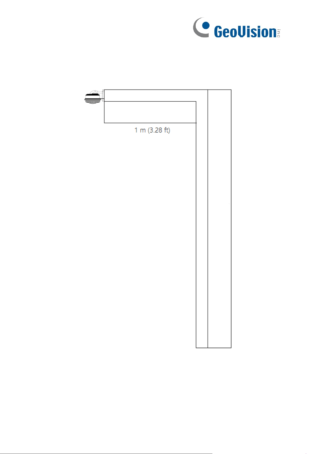
166
B. Note for Fisheye Camera with IR LED
When installing GV-Mount211-7 / 508 / 430 to GV-PFER12800, leave a distance of 1 M
(3.28 ft) or mote between the camera body and nearby walls to avoid reflected glare by
IR LED.