
MILWAUKEE TOOL
l
www.milwaukeetool.com
13135 W. LISBON RD., BROOKFIELD, WI 53005
Drwg. 1
BULLETIN NO.
54-06-2170
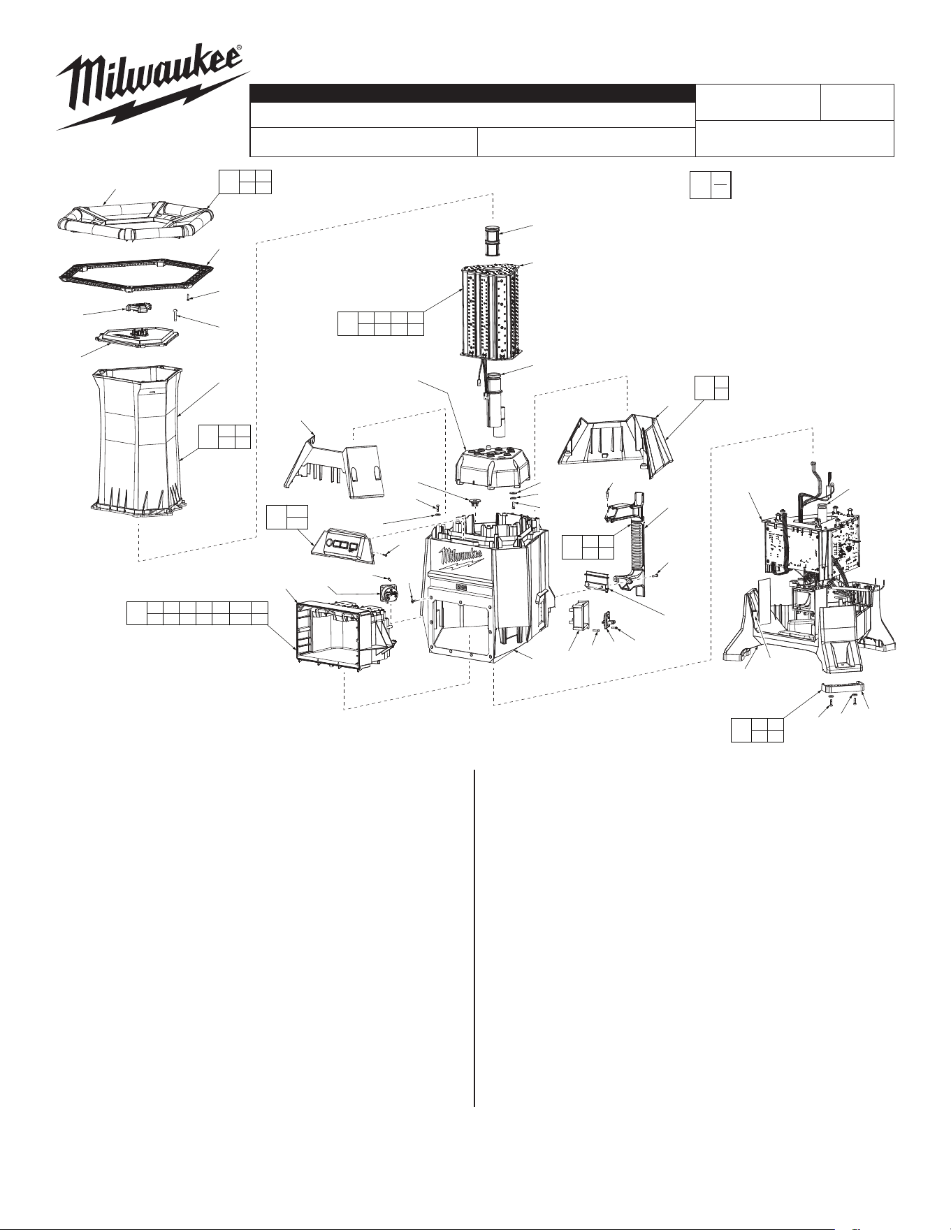
SERVICE PARTS LIST
FIG. PART NO. DESCRIPTION OF PART NO. REQ.
1a 06-82-2250 M5 x 29mm Pan Hd. T-25 Screw (6)
1b --------------- Top Handle (1)
1c --------------- Top handle Cover (1)
1d 06-82-0190 M3 x 14mm St. T-10 Screw (13)
1e --------------- Chimney Cap (1)
1f --------------- Top lens (1)
1g --------------- Main Lens (1)
2 06-82-0195 M4 x 13.5mm Pan Hd. Screw (10)
3 --------------- Housing Cone Front (1)
4 --------------- Housing Cone Back (1)
5 45-76-0077 Top Chimney (1)
6 --------------- Light Engine (1)
7 --------------- Chimney Adapter (1)
8 --------------- Light Engine Base (1)
9 45-88-2060 Washer (16)
10 05-88-1210 M4 x 14mm Pan Hd. T-20 Screw (8)
12 43-40-0050 Rubber Piston (1)
13 --------------- UI Assembly (1)
13a --------------- M3 x 11mm Pan Hd. Screw (12)
14 --------------- Main Housing (1)
15 05-78-0135 M4 x 12mm Pan Hd. Phillips Screw (9)
16 --------------- Side Handle (1)
CATALOG NO. 2151-20
REVISED BULLETIN
SPECIFY CATALOG NO. AND SERIAL NO. WHEN ORDERING PARTS
M18™ RADIUS™ Site Light
STARTING
SERIAL NO.
DATE
Mar. 2020
WIRING INSTRUCTION
J42A
See Page 2 and 3
FIG. PART NO. DESCRIPTION OF PART NO. REQ.
18 --------------- Side Handle Support (1)
19 23-33-0005 AC Output (1)
22 23-33-0010 AC Input (1)
23 --------------- Inlet Base (1)
24 --------------- PCB Holder Assembly (1)
25 45-76-0076 Chimney Tube (1)
27 --------------- Box Assembly (1)
28 42-20-2002 Bottom Base (1)
29 --------------- Rubber Boot (1)
30 31-44-5001 Screw Cover (2)
32 06-82-1020 M4 x 14mm Pan Hd. T-20 Screw (2)
40 14-34-0005 Top Handle Assembly (1)
41 44-06-1001 Lenses Assembly (1)
42 23-28-0001 Light Engine Service Assembly (1)
43 43-76-0045 Cone Housing Assembly (1)
44 14-74-0115 Rubber Boot Kit (3)
45 05-90-0225 Spring Washer (8)
46 42-62-0005 Side Handle Assembly (1)
47 14-20-2200 Base / PCBA Assembly (1)
48 12-20-2055 Service nameplate (Not Shown) (1)
49 10-20-3000 Warning Label (Not Shown) (1)
0
00
EXAMPLE:
Component Parts (Small #)
Are Included When Ordering
The Assembly (Large #).
1b
13a
(x4)
15
(x9)
19
12
27
4
16
24
25
18
14
2
(x2)
2
(x6)
9
(x6)
30
(X2)
28
9
(x2)
29
23
1d
(x4)
22
13a
(x4)
13a
(x4)
32
(x2)
1c
1g
1d
(x9)
5
6
7
8
1a
(x9)
1e
3
2
(x2)
1f
45(x8)
10(x8)
9(x8)
13
13a
43
3
4
47
1d 2 9 12 13 13a 14
15 19 22 23 24 27
42
5 6 7 8
9 10 45
46
2 16
18 32
41
1a 1e
1f 1g
40
1b 1c
1d
44
2 9
29
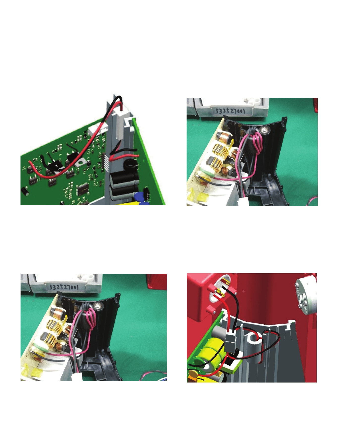
Wire Routing:
1. Connect wire harness from AC board to the control
board wire harness.
2. Set Ferrite Bead to PCB Holder with a screw
and washer.
3. Gather wires from terminals and fasten wire clip to
housing.
4. Connect wire harness from power board to AC
inlet terminal.
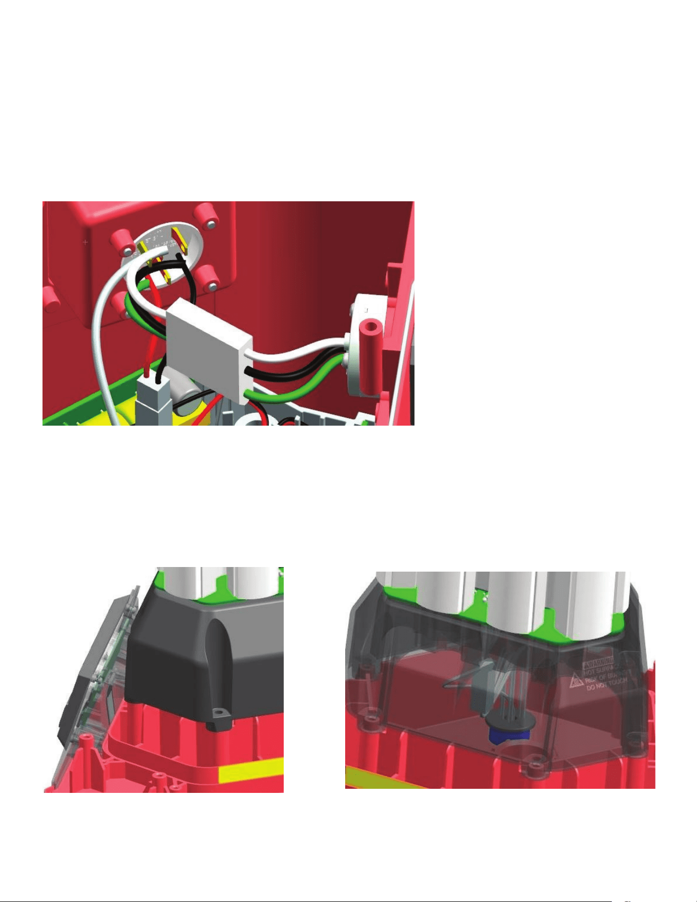
Wire Routing:
5. Connect AC inlet terminal to Output terminal.
6. Connect Wires from control board to UI board. 7. Connect Wires from Control board to Light Engine
and ground wire from AC inlet to light engine.