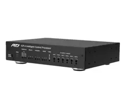
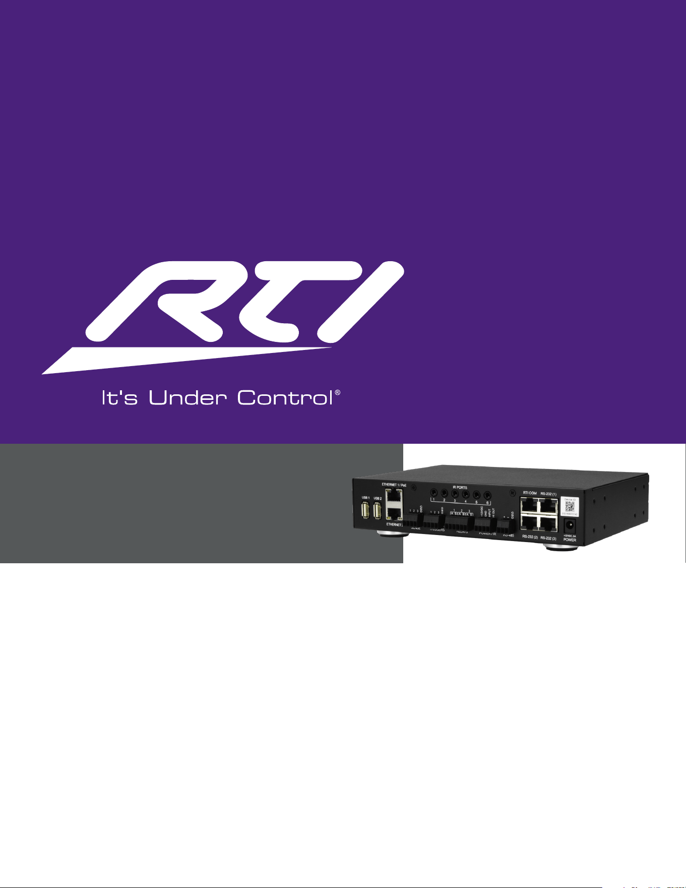
RTI-ICP-4
Intelligent control processor with six IR ports, three two-way RS-232 ports, three relay/
trigger outputs, three sense inputs and dual Gigabit Ethernet with PoE.
RTI-ICP-4
User Manual

Page 2 ICP-4 User Manual
Introduction ........................................................................................................................................ 3
Features ............................................................................................................................................. 3
What’s in the box ................................................................................................................................ 3
Specifications ...................................................................................................................................... 4
Front Panel Overview ........................................................................................................................... 5
Rear Panel Overview ............................................................................................................................ 6
Mounting ............................................................................................................................................ 7
Initial Setup ........................................................................................................................................ 7
Programming the ICP-4 ........................................................................................................................ 8
Updating Firmware .............................................................................................................................. 8
IR Ports .............................................................................................................................................. 8
IR Output Gain Adjustment ................................................................................................................... 8
Power / IR Terminal ............................................................................................................................. 8
RS-232 Ports .................................................................................................................................... 10
RS-232 Port Pinout ............................................................................................................................ 10
Sense Inputs..................................................................................................................................... 10
Relay / Trigger Outputs .......................................................................................................................10
Ethernet and Power over Ethernet ....................................................................................................... 10
USB Ports ......................................................................................................................................... 11
RTI COM Port .................................................................................................................................... 11
Status Indicators ............................................................................................................................... 12
Reset Buttons ................................................................................................................................... 12
RTI Accessories Supported.................................................................................................................. 12
Troubleshooting ................................................................................................................................ 13
Maintenance ..................................................................................................................................... 14
Damage Requiring Service .................................................................................................................. 14
Safety Suggestions ............................................................................................................................ 15
Regulatory Compliance ....................................................................................................................... 15
Support ............................................................................................................................................ 17
Contacting RTI .................................................................................................................................. 17
Warranty .......................................................................................................................................... 17

Page 3 ICP-4 User Manual
Introduction
The ICP-4 is a whole-house control processor that balances capability against footprint. It suits residential and
commercial projects equally — homes, offices, meeting rooms and small venues — and runs the same
complex drivers as the rest of the range from a half-width 1U chassis. Where a project grows beyond a single
unit, it can be expanded through additional ICP units and a whole range of expansion accessories.
Control programs are authored in RTI's Integration Designer® software (version 12.0 or higher) on a Windows
PC and downloaded over USB or Ethernet. Drivers run on a JavaScript-based platform, and the processor runs
Yocto with embedded Linux operating system with a real-time clock for time-based events and sleep timers.
Features
• Six (6) IR output ports, 5V mono 3.5mm, individually adjustable by potentiometer
• Three (3) two-way RS-232 ports on RJ-45 connectors
• Three (3) programmable relay/trigger outputs rated 3A @ 30VDC
• Three (3) assignable digital/closure sense inputs, 3-24VDC
• High-current IR output terminal (200mA) for blasters and long IR runs
• Dual Gigabit Ethernet (10/100/1000) on two separate network interfaces
• Power over Ethernet or DC powered
• Two (2) USB-A host ports for supported accessories and dongles
• USB-C programming port
• RTI COM port for the ZM-24 Zigbee® transceiver module
• Real-time clock with Network Time Protocol synchronization
• Non-volatile flash storage retains the system configuration without power
• Field-upgradeable firmware with failsafe storage during download
• Front panel status indicators and multifunction reset buttons
• Metal enclosure, half-width 1U; surface mountable, or rack mountable with the optional rack kit
What’s in the box
• One (1) ICP-4 Intelligent Control Processor
• One (1) 12VDC power supply with international interchangeable blades
• Three (3) RJS-232 connector
• Two (2) Rack mount brackets
• Four (4) Rack screws
• Four (4) removable feet (shipped already installed)
• Terminal blocks (phoenix connectors, shipped plugged into the unit)
• One (1) Quick reference card with QR code to this online reference guide
Page 4 ICP-4 User Manual
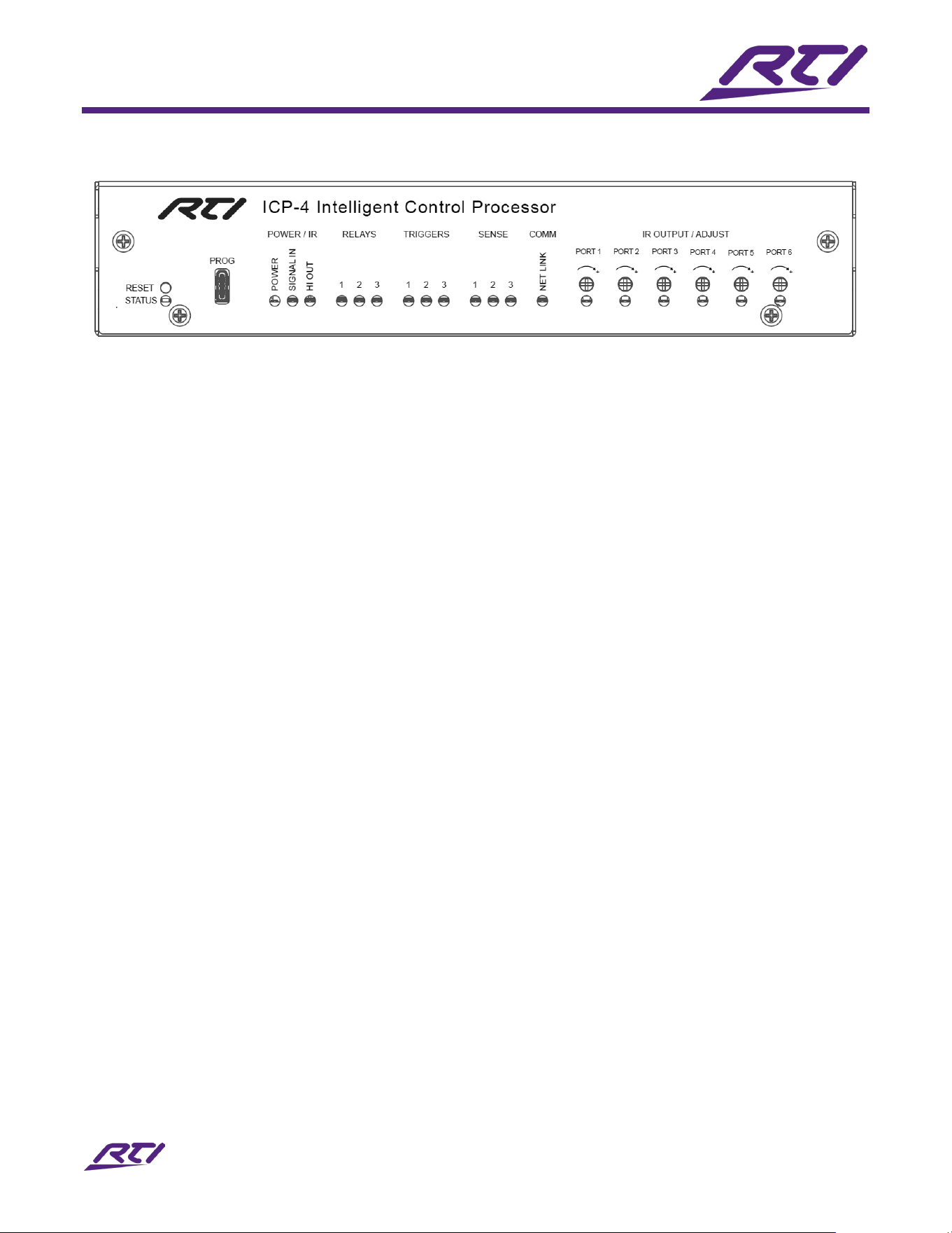
Specifications
PROCESSING & MEMORY:
PROCESSOR
NXP i.MX8MM
OPERATING SYSTEM
Yocto with embedded Linux
RAM
3GB
FLASH STORAGE
16GB
REAL-TIME CLOCK
Yes, Time-Based Events and Sleep Timers, NTP Synchronization
DRIVER PLATFORM
Javascript Based, Node.js Capable
IR:
IR OUTPUT PORTS
Six (6), Output Only
IR OUTPUT CONNECTOR
5v Mono 3.5mm
IR OUTPUT LEVEL
Variable By Potentiometer, Adjustable Per Port
IR OUTPUT CURRENT
100mA Maximum Per Port
HIGH OUT TERMINAL
200mA Maximum; Up To 10 Emitters, an IR Blaster, or IR To 1000 Ft. Max
IR FREQUENCY RANGE
15khz - 460khz
Serial:
RS-232 PORTS
Three (3), Two-Way
RS-232 CONNECTOR
RJ-45
RS-232 BAUD RATE
Up To 19,200 bps
Sense Inputs & Relay / Trigger Outputs:
SENSE INPUTS
Three (3), Voltage sense
SENSE INPUT VOLTAGE
3 – 24VDC; Off / Low Must Not Exceed 1VDC
RELAY / TRIGGER OUTPUTS
Three (3), Programmable
RELAY RATING
3A@30VDC Max Each Relay
TRIGGER OUTPUT RATING
12VDC@100mA Max Each Trigger Output
RELAY DEFAULT STATE
Normally Open; Programmable as Normally Closed While Powered
CONNECTOR
Phoenix Terminal Blocks, A / B Per Channel
Power / IR Terminal:
+12VDC TERMINAL
Positive Supply, Internally Tied to the Power Jack; Powers External IR
Receivers
GROUND TERMINAL
Common Ground Reference
INPUT TERMINAL
System Trigger Codes; Also Accepts an RM433 433MHz Receiver
HI OUT TERMINAL
High-Current (200mA) IR Output
Network & Expansion:
ETHERNET PORTS
Two (2) Ethernet 1 (PoE) and Ethernet 2
ETHERNET SPEED
Gigabit, 10/100/1000 Mb/S
NETWORK INTERFACES
Configurable as Switch or Two Separate NICs
USB-A HOST (REAR)
Two (2) USB 2.0, For Supported Third-Party Dongles
USB-C (PROGRAMMING)
One (1) USB 2.0 Device, For Integration Designer (ID12.0 or higher)
RTI COM
One (1) Supports The ZM-24 Zigbee® Transceiver Module
WI-FI
No
Control & Programming:
PROGRAMMING SOFTWARE
RTI Integration Designer® (Must be ID12.0 or higher)
DOWNLOAD METHODS
USB-C Programming Port or Ethernet
FIRMWARE
Field Upgradeable
Existing Firmware Retained Until A New Download Completes Successfully
BUTTONS
Multifunction By Hold Time — DHCP, Reset, and Factory Reset
Power:
DC INPUT
12VDC, 2A
DC CONNECTOR
5.5mm Barrel, Negative Case
POWER SUPPLY
International 110-240v AC to DC, Interchangeable Blades
POWER OVER ETHERNET
IEEE 802.3af Type 1, Up To 15.4W, on Ethernet 1
Enclosure & Mounting:
MATERIAL
Metal
COLOR
Black
WIDTH
8.5" (215mm)
DEPTH
6.0" (152mm)
HEIGHT
1.7" (44mm), Half-Width 1U
WEIGHT
115.4oz (890g)
MOUNTING
Surface Mountable or Rack Mountable (Kit Included)
Compliance:
REQUIRED MARKS
CE, FCC, RCM, UKCA
Page 5 ICP-4 User Manual
Front Panel Overview
I
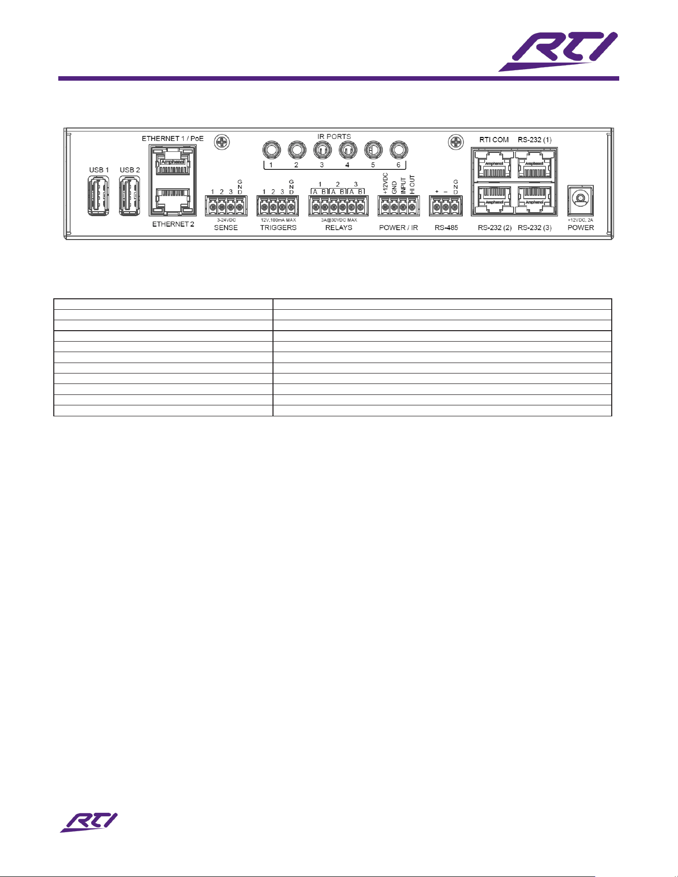
CP-4 FRONT PANEL
The front panel carries the following controls and indicators.
• Status indicator at the left-hand side of the panel
• Indicators for power, IR (in/out), relays, triggers, sense, comm, and IR port output
• IR output adjustment potentiometers
• USB-C programming port
• Multifunction RESET button for DHCP reset and factory reset
Page 6 ICP-4 User Manual
Rear Panel Overview
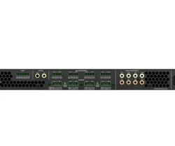
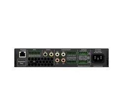
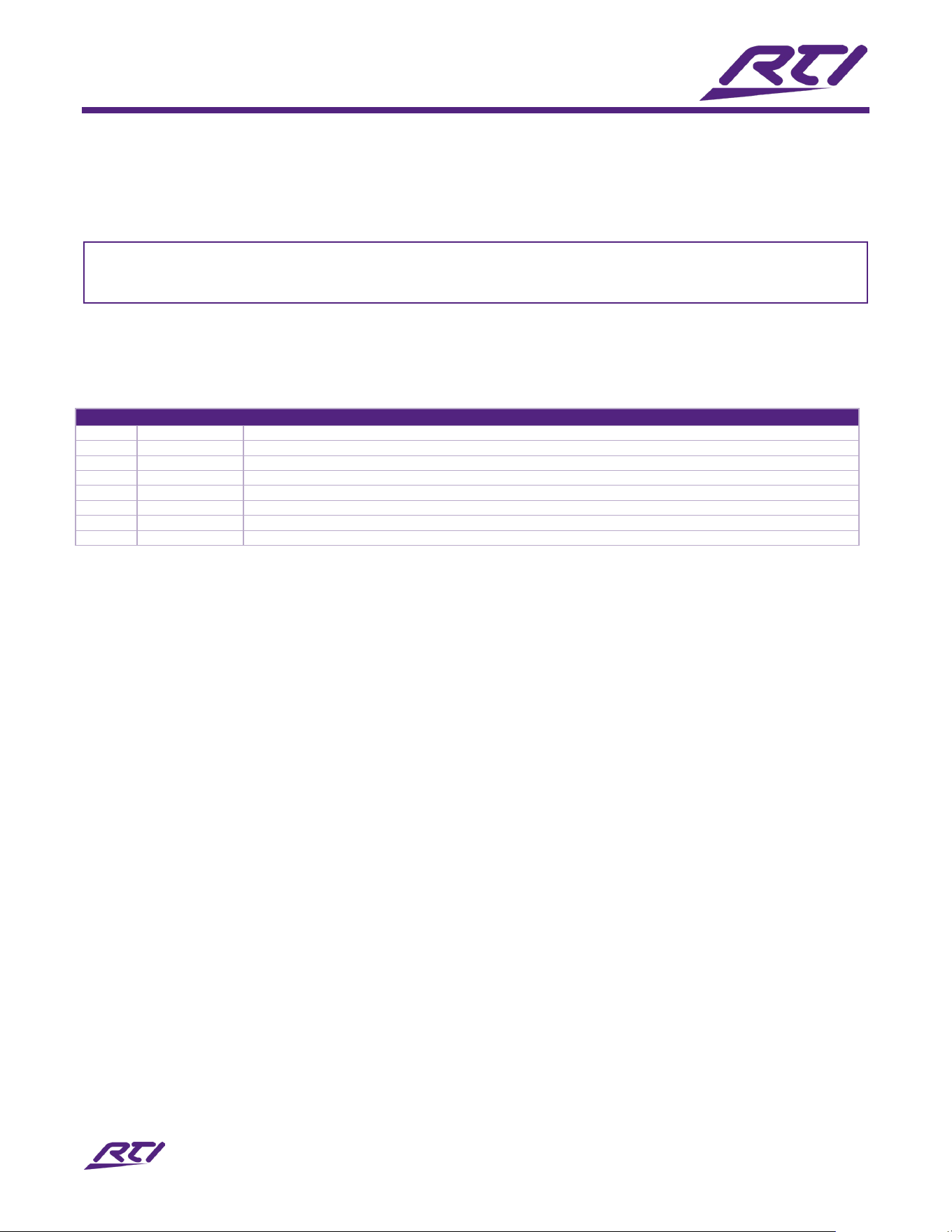
ICP-4 REAR PANEL CONNECTIONS
Connectors are grouped left to right as follows.
USB 1 / USB 2
USB-A Host Ports for Supported Accessories and Dongles
ETHERNET 1 / POE
Gigabit Ethernet; Also Powers the Processor Over PoE
ETHERNET 2
Gigabit Ethernet; Configurable as Separate NIC or Switch with Ethernet 1
SENSE INPUTS 1-3
Voltage / Closure, A and B options
TRIGGER OUTPUTS 1-3
Voltage Triggers, 12VDC 100mA
RELAY OUTPUTS 1-3
Each Relay is Separate with Two Connections per Contact
POWER / IR
+12vdc, GND, Input and Hi Out Terminals
IR PORTS 1-6
5v Mono 3.5mm IR Outputs (Does Not Accept MPIO Accessories)
RS-232 1-3
RJ-45 Two-Way Serial Ports
RTI COM
Connection for ZM-24 Zigbee® Transceiver
POWER
+12vdc, 2A (Not Required if Using PoE)

Page 7 ICP-4 User Manual
Mounting
The ICP-4 is a half-width 1U product. It can be used freestanding (with included removeable feet) or with the
supplied rack mount kit which allows a single ICP-4 to be rack mounted in the center of the rack slot.
Initial Setup
Work through these steps to get the ICP-4 installed, powered, connected and ready to receive its first system
file. The sections that follow cover each connector group in detail.
1. Install the ICP-4 on its surface or in its rack. See Mounting above.
2. Connect IR emitters to the IR PORTS. Each port is a 5V mono 3.5mm output.
3. Connect any IR blaster or long IR run to the HI OUT terminal in the POWER / IR block.
4. If the system uses an external IR receiver or an RM433 433MHz receiver, wire it to the +12VDC, GND
and INPUT terminals in the POWER / IR block.
5. Connect two-way serial devices to the RS-232 ports using Cat-5/6 cable terminated to the pinout given
in this guide.
6. Wire contact-closure and voltage sources into the SENSE INPUTS terminal blocks, and wire the devices
you intend to switch into the RELAY / TRIGGER OUTPUTS terminal blocks.
7. If the system uses RTI Zigbee® handheld controllers, connect a ZM-24 transceiver module to the RTI
COM port.
8. Connect the network. Use ETHERNET 1 / PoE if the switch supplies Power over Ethernet; the processor
will draw its power from that port. ETHERNET 2 is a second, separate network interface.
9. If the network does not supply PoE, connect the supplied 12VDC power supply to the POWER jack and
then to a suitable power source.
10. Power on the connected source and destination equipment.
11. Watch the front panel Status indicator. Solid red means the operating system is starting. Solid green
means the system file and drivers have loaded. The indicator goes off when the processor is ready for
use.
12. Update the firmware before programming. See Updating Firmware.
13. Create the control program in Integration Designer® (ID12.0 or higher) and download it to the processor
over the USB-C programming port or over Ethernet.
14. With the system file loaded, verify control of each connected device. If a device is not responding over
IR, adjust that port's output level using the IR adjustment potentiometer behind the front cover.
NOTE: The ICP-4 must be programmed to operate. It will not control anything until a system file has been
downloaded.

Page 8 ICP-4 User Manual
Programming the ICP-4
All programming is done using RTI's Integration Designer® (ID12.0 or higher) software (ID12.0 or higher) on
a Windows PC. The software creates the control program, referred to as an ID file, and identifies each
processor by a unique identifier.
Programs are downloaded over the USB-C programming port or over Ethernet. Network settings, sense input
modes, and relay and trigger output modes are all configured within Integration Designer® (ID12.0 or higher)
and downloaded as part of the system file.
Updating Firmware
It is highly recommended that this and all RTI products have the latest firmware installed. Firmware is
available by selecting the Firmware button in the AVPro Connect section of the AVPro Global website at
https://www.avproglobal.com
NOTE: The ICP-4 retains the currently installed firmware while a new file downloads and only transfers over
once the download has completed successfully. A failed or interrupted download will not leave the processor
without working firmware.
IR Ports
The ICP-4 provides six IR output ports on 5V mono 3.5mm connectors. The ports are output only. Infrared
transmission covers a frequency range of 15kHz to 460kHz, and each port supplies up to 100mA.
IR Output Gain Adjustment
IR output level is adjustable per port by potentiometer.
1. The IR output adjustment potentiometers are located on the front panel.
2. Locate the potentiometer for the affected port.
3. Rotate it clockwise for higher output power, or counterclockwise for lower output power.
4. Test the device again and repeat until control is reliable.
NOTE: The IR output indicator illuminates in response to an output signal on any port.
Power / IR Terminal
TERMINAL: +12VDC
Positive power supply connection. It is internally tied to the power jack. This can be used to power an external
IR receiver.
TERMINAL: GND
Common ground connection. Use this ground reference for any device connected to the +12VDC, INPUT or HI
OUT terminals.

Page 9 ICP-4 User Manual
TERMINAL: INPUT
Input connection for system trigger codes. This terminal can also be used to connect an RM433 433MHz
receiver.
TERMINAL: HI OUT
High current (200mA) IR output connection. This can be used to power up to 10 infrared emitters, an IR
blaster, or to extend IR control over a long distance, up to 1000 ft. maximum.
Page 10 ICP-4 User Manual
RS-232 Ports
The ICP-4 provides three two-way RS-232 ports on RJ-45 connectors for bi-directional communication with
supported devices. The connectors carry no LEDs. Serial communication is supported at baud rates up to
19,200 bps through the applicable RTI driver.
IMPORTANT NOTE
RS-232 communication cabling should be kept short and well away from mains wiring. Confirm the baud
rate set in Integration Designer® (ID12.0 or higher) matches the connected device.
RS-232 Port Pinout
RJ-45 (ICP-4 RS-232 PORT)
1
DSR
Data Set Ready
2
DCD
Carrier Detect
3
DTR
Data Terminal Ready
4
GND
Signal Ground / Common
5
RXD
Receive Data
6
TXD
Transmit Data
7
CTS
Clear To Send
8
RTS
Request To Send
NOTE: Pins 1, 2 and 3 are wired for compatibility but are not required for communication with supported
devices. Pins 4 through 8 carry the signals used by RTI drivers.
Sense Inputs
The ICP-4 provides two digital sense inputs on phoenix terminal blocks, with A and B terminals per input. On
sensing voltage, events such as a macro or command can be triggered automatically.
Sense voltage input: Connect the positive lead from the voltage source to Side A of the sense input
and the ground lead to Side B.
NOTE: Sense inputs accept 3-24VDC. The off or low state must not exceed 1VDC.
Relay Outputs
Three programmable relay outputs are provided on phoenix terminal blocks, with A and B terminals per
output. Relay modes are configured within Integration Designer® (ID12.0 or higher). Connect the A and B
contact terminals of a relay to the device.
NOTE: All relays are Normally Open when not energized and may be programmed to behave Normally Closed
while power is applied to the processor. Each relay is rated 3A@30VDC.

Page 11 ICP-4 User Manual
Trigger Outputs (Voltage Only)
Three programmable trigger outputs are provided on phoenix terminal blocks and can provide
12VDC@100mA. Trigger modes are configured within Integration Designer® (ID12.0 or higher). Connect the
positive lead to a trigger output (1-3) and the negative lead to the ground (GND) terminal.
Ethernet and Power over Ethernet
Two Gigabit Ethernet ports are provided. ETHERNET 1 / PoE and ETHERNET 2 operate on two separate
network interfaces, or they can be tied together as a switch. Both ports support 10/100/1000 Mb/s.
ETHERNET 1 / PoE will power the processor from a switch or injector supplying IEEE 802.3af Type 1 power, up
to 15.4W. When PoE is used, the 12VDC power supply is not required.
Network settings such as the IP address, and the mode of operation, are configured within Integration
Designer® (ID12.0 or higher). Ethernet may also be used to download system files to the processor.
NOTE: The MAC address is programmed during manufacture, stored in non-volatile memory, and drawn from
a range assigned to RTI. The MAC address label is applied near the Ethernet ports.
USB Ports
USB 1 AND USB 2 (REAR)
Two USB-A host ports, USB 2.0. These are provided for connection of supported third-party dongles, such as a
Wi-Fi access point or an audio output adaptor, and for future accessories and features.
USB-C PROGRAMMING PORT
USB 2.0 device port used for connection to Integration Designer® (ID12.0 or higher) on a Windows PC, for
download of program files and firmware updates. The port presents an RTI-specific USB identifier so the
software can recognise the processor.
RTI COM Port
The RTI COM port supports a ZM-24 Zigbee® transceiver module, providing 2.4GHz communication with
compatible RTI handheld controllers. Refer to the ZM-24 operation guide for installation instructions.
Page 12 ICP-4 User Manual
Status Indicators
Indicators are red unless otherwise specified, diffused and flush mounted.
INDICATOR BEHAVIOUR:
POWER
SOLID — POWER APPLIED
STATUS — SOLID RED
PROCESSOR IS PLUGGED IN AND BOOTING; THE OPERATING SYSTEM IS
STARTING UP
STATUS — SOLID GREEN
SYSTEM FILE AND DRIVERS HAVE BEEN LOADED
STATUS — OFF
PROCESSOR HAS FINISHED STARTING UP AND IS READY FOR USE
STATUS — BLINK GREEN
EXECUTING COMMANDS OR MACROS DURING OPERATION
SIGNAL IN
SOLID RED — RESPONSE TO INPUT SIGNAL
HIGH OUT
SOLID RED — ENABLED
RELAY
SOLID RED — ACTUATED
TRIGGER
SOLID RED — RESPONSE TO SIGNAL
SENSE
SOLID RED — RESPONSE TO INPUT SIGNAL
IR OUTPUT
SOLID RED — RESPONSE TO OUTPUT SIGNAL
NET LINK
SOLID RED — SUCCESSFULLY CONNECTED TO ETHERNET
Reset Buttons
The front panel button is multifunction, with the action determined by how long the button is held.
• Reboot.
• Press and hold for between 2 to 5 seconds.
• Reboots the processor.
• DHCP reset.
• Press and hold for between 10 to 30 seconds.
• Returns the processor to DHCP addressing.
• Factory reset.
• Press and hold for longer than 30 seconds.
• Returns the processor to its factory configuration.
• The system file must be downloaded again afterwards.
RTI Accessories Supported
SUPPORTED CONNECTIONS:
TOUCHPANELS
ETHERNET
REMOTE CONTROLS
WIFI VIA ROUTER FROM ETHERNET, ZIGBEE® 2.4GHZ VIA COM PORT TO
ZM-24; 433MHZ VIA TERMINALS TO RM433
EXPANSION PROCESSORS
ETHERNET
THIRD-PARTY DEVICES
ETHERNET or RS-232 CONTROL — AUDIO, VIDEO, CABLE BOXES, TV,
PROJECTORS, LIGHTING, HVAC, SECURITY

Page 13 ICP-4 User Manual
Troubleshooting
Work through the checks below before contacting Technical Support.
THE ICP-4 DOES NOT RESPOND TO ANY COMMANDS
The processor must be programmed to operate. Confirm that a system file has been created in Integration
Designer® (ID12.0 or higher) and downloaded over the USB-C programming port or over Ethernet. Check the
Status indicator: if it is off, the processor has started up and is ready.
THE PROCESSOR WILL NOT POWER UP
If powering over PoE, confirm the network cable is in ETHERNET 1 / PoE and that the switch or injector
supplies IEEE 802.3af Type 1 power. Otherwise confirm the 12VDC 2A supply is connected to the POWER jack
and to a live outlet.
A DEVICE IS NOT RESPONDING TO INFRARED COMMANDS
Confirm the IR output indicator illuminates when a command is sent. If it does, the port is delivering the code
and the issue is at the emitter. Check emitter placement over the device's IR window, then remove the front
cover and adjust that port's potentiometer clockwise for higher output power. For an IR blaster or a long run,
use the HI OUT terminal rather than a port output.
A SERIAL DEVICE IS NOT RESPONDING
Confirm the Cat-5/6 run is terminated to the pinout given in this guide, and check the baud rate set in
Integration Designer® (ID12.0 or higher) against the device's own setting. Supported rates run up to 19,200
bps.
A SENSE INPUT IS NOT TRIGGERING EVENTS
Confirm the sense input mode in Integration Designer® (ID12.0 or higher) matches the wiring. For contact
closure, conductors go to both sides (A and B) of the input. For a voltage trigger, the positive lead goes to
Side A and the ground lead to Side B, with 3-24VDC present. Confirm the off state does not exceed 1VDC.
THE NETWORK CONNECTION IS UNRELIABLE
ETHERNET 1 and ETHERNET 2 are separate network interfaces. Confirm the cable is in the intended port and
that the Net Link indicator is lit. Check the IP configuration in Integration Designer® (ID12.0 or higher).

Page 14 ICP-4 User Manual
Maintenance
To clean the ICP-4, lightly dampen a lint-free cloth with plain water or a mild detergent and wipe the outer
surfaces.
NOTE: Do not use harsh chemicals as damage to the unit may occur.
Damage Requiring Service
The unit should be serviced by qualified service personnel when:
• The power supply cord or the plug has been damaged.
• Objects have fallen or liquid has been spilled into the unit.
• The unit has been exposed to rain.
• The unit does not appear to operate normally or exhibits a marked change in performance.
• The unit has been dropped, or the enclosure has been damaged.
Do not attempt any service beyond that described in these operating instructions. Refer all other service
needs to qualified service personnel.

Page 15 ICP-4 User Manual
Safety Suggestions
Read and Follow Instructions. Read all safety and operating instructions before operating the unit.
Retain Instructions. Keep the safety and operating instructions for future reference.
Heed Warnings. Adhere to all warnings on the unit and in the operating instructions.
Heat. Keep the unit away from heat sources such as radiators, heat registers, stoves, etc., including amplifiers that produce
heat.
Power Sources. Connect the unit only to a power supply of the type described in the operating instructions, or as marked
on the unit.
Power Cord Protection. Route power supply cords so that they are not likely to be walked on or pinched by items placed
on or against them, paying particular attention to the cord plugs at power receptacles and at the point at which they exit
from the unit.
Water and Moisture. Do not use the unit near water—for example, near a sink, in a wet basement, near a swimming pool,
near an open window, etc.
Object and Liquid Entry. Do not allow objects to fall or liquids to be spilled into the enclosure through openings.
Ventilation. Do not obstruct the enclosure vents. Allow clearance around the unit for airflow.
Servicing. Do not attempt any service beyond that described in the operating instructions. Refer all other service needs to
qualified service personnel.
Regulatory Compliance
The ICP-4 carries CE, FCC, RCM and UKCA marks.
DECLARATION OF CONFORMITY (DOC)
The Declaration of Conformity for this product can be found on the AVPro Global website https://www.avproglobal.com
FEDERAL COMMUNICATIONS COMMISSION NOTICE
This equipment has been tested and found to comply with the limits for a Class B digital device, pursuant to Part 15 of the FCC
Rules. These limits are designed to provide reasonable protection against harmful interference in a residential installation. Any
changes or modifications not expressly approved by the party responsible for compliance could void the user's authority to
operate the device.
This equipment generates, uses, and can radiate radio frequency energy and, if not installed and used in accordance with the
instructions, may cause harmful interference to radio communications. However, there is no guarantee that interference will not
occur in a particular installation.
If this equipment does cause harmful interference to radio or television reception, which can be determined by turning the
equipment off and on, the user is encouraged to try to correct the interference by one or more of the following measures:
Reorient or relocate the receiving antenna.
• Increase the separation between the equipment and the receiver.
• Connect the equipment into an outlet on a circuit different from that to which the receiver is connected.
• Consult the dealer or an experienced radio/TV technician for help.
This device complies with Part 15 of the FCC Rules. Operation is subject to the following two conditions:
1. This device may not cause harmful interference.
2. This device must accept any interference received including interference that may cause undesired operation.

Page 16 ICP-4 User Manual
INDUSTRY CANADA COMPLIANCE STATEMENT
This device complies with Industry Canada license-exempt RSS standard(s). Operation is subject to the following two conditions:
1. This device may not cause harmful interference.
2. This device must accept any interference received including interference that may cause undesired operation.
Cet appareil est conforme avec Industrie Canada exempts de licence standard RSS (s). Son fonctionnement est soumis aux deux
conditions suivantes:
1. Ce dispositif ne peut causer des interférences nuisibles.
2. Cet appareil doit accepter toute interférence reçue y compris des interférences qui peuvent provoquer un
fonctionnement indésirable.

Page 17 ICP-4 User Manual
Support
If you are encountering any problems or have a question about your RTI product, first refer to the
Troubleshooting section of this guide, then contact RTI Technical Support for assistance.
RTI provides technical support by telephone or e-mail. For the highest quality service, please have the
following information ready:
• Your name
• Company name
• Telephone number
• E-mail address
• Product model and serial number (if applicable)
If you are having a problem with hardware, please note the equipment in your system, a description of the
problem, and any troubleshooting you have already tried.
RETURN AUTHORIZATION
Please do not return products to RTI without return authorization.
Contacting RTI
For news about the latest updates, new product information, and new accessories, please visit our web site at:
www.rticontrol.com
For general information, you can contact RTI at:
AVPro Global Holdings
2222 E 52nd Street North
Sioux Falls SD 57104
Tel: 877-886-5112
Tech Support: info@avproglobal.com
Warranty
THE BASICS
RTI warrants new products for a period of three (3) years (excluding consumables such as rechargeable batteries which are
warrantied for one (1) year) from the date of purchase by the original purchaser (end user) directly from RTI / Pro Control
(herein referred to as “RTI”), or an authorized RTI dealer.
Warranty claims may be initiated by an authorized RTI dealer using the original dated sales receipt or other proof of
warranty coverage. In the absence of the receipt of purchase from the original dealer, RTI will provide warranty coverage
extension of six (6) months from the date code of the product.
Note: RTI warranty is limited to the provisions set forth in this policy and does not preclude any other warranties offered by
third parties who are solely responsible for those other warranties.
COVERAGE DETAILS
Except as specified below, this warranty covers defects in product material and workmanship. The following are not covered
by the warranty:
• Product purchased via unauthorized sellers or internet sites will not be serviced — regardless of purchase date.

Page 18 ICP-4 User Manual
• Damages caused by accident, misuse, abuse, neglect or acts of God.
•
Cosmetic damage, including, but not limited to, scratches, dents and normal wear and tear.
•
Failure to follow instructions contained in the Product Installation Guide.
•
Damages due to products used in an application or environment other than that for which it was intended, improper
installation procedures or adverse environmental factors such as incorrect line voltages, improper wiring, or insufficient
ventilation.
•
Repair or attempted repair by anyone other than RTI and Pro Control or authorized service partners.
•
Failure to perform recommended periodic maintenance.
•
Causes other than product defects, including lack of skill, competence or experience of user.
•
Damage due to shipment of this product (claims must be made to the carrier).
• Altered unit or altered serial number: defaced, modified or removed.
LIMITATIONS OF LIABILITY
RTI Control is also not liable for:
• Damages caused by its products or for failure of its products to perform, including any labor costs, lost profits, lost
savings, incidental damages, or consequential damages.
•
Damages based upon inconvenience, loss of use of the product, loss of time, interrupted operation, commercial loss,
any claim made by a third party or made on behalf of a third party.
•
Loss of, or damage to, data, computer systems or computer programs.
RTI's liability for any defective product is limited to repair or replacement of the product, at the sole discretion of RTI.
In cases where the warranty policy conflicts with local laws, the local laws will be adopted.

AVPro Global Holdings, LLC
2222 E 52nd Street N
Sioux Falls, SD 57104
www.avproglobal.com
© 2026 AVPro Global Holdings, LLC. All rights reserved.