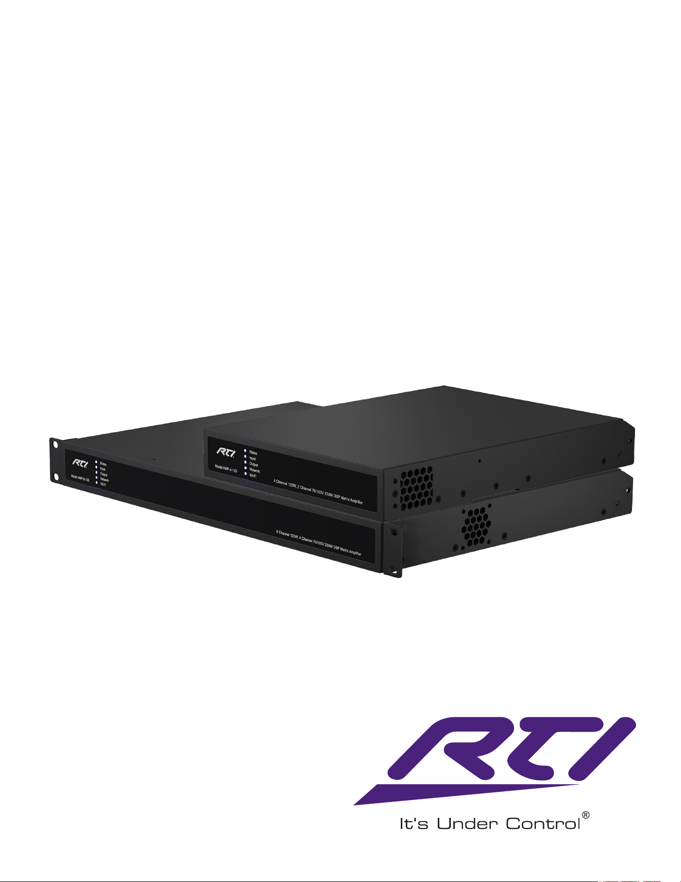
Installation and Operation Guide
RTI Commercial Ampliers
AMP-4-125 4Channel125W8Ω,
2Channel70/100V250WDSPMatrixAmplier
AMP-8-125 8Channel125W8Ω,
4Channel70/100V250WDSPMatrixAmplier
Technical Support: [email protected] - Customer Service: [email protected]
2
AUDIO DISTRIBUTION
Important Safety Instructions
1. Read these instructions.
2. Keep these instructions.
3. Heed all warnings.
4. Follow all instructions.
5. Do not use this apparatus near water.
6. Do not submerge the equipment in water or liquids.
7. Donotuseanyaerosolspray,cleaner,disinfectantor
fumiganton,nearorintotheequipment.
8. Clean only with a dry cloth.
9. Do not block any ventilation opening. Install in
accordancewiththemanufacturer’sinstructions.
10. Donotinstallnearanyheatsourcessuchasradiators,
heatregisters,stoves,orotherapparatus(including
ampliers)thatproduceheat.
11. Toreducetheriskofelectricalshock,thepowercord
shall be connected to a mains socket outlet with a
protective earthing connection.
12. Donotdefeatthesafetypurposeofthepolarizedor
groundingtypeplug.Apolarizedplughastwoblades
with one wider than the other. A grounding type plug
has two blades and a third grounding prong. The wide
bladeorthethirdprongareprovidedforyoursafety.If
theprovidedplugdoesnottintoyouroutlet,consult
anelectricianforreplacementoftheobsoleteoutlet.
13. Protectthepowercordfrombeingwalkedonor
pinchedparticularlyatplugs,conveniencereceptacles,
andthepointwheretheyexitfromtheapparatus.
14. Donotunplugtheunitbypullingonthecord,usethe
plug.
15. Onlyuseattachments/accessoriesspeciedbythe
manufacturer.
16. Unplug this apparatus during lightning storms or when
unusedforlongperiodsoftime.
17. Referallservicingtoqualiedservicepersonnel.
Servicing is required when the apparatus has been
damagedinanyway,suchaspowersupplycordor
plugisdamaged,liquidhasbeenspilledorobjects
havefallenintotheapparatus,theapparatushas
beenexposedtorainormoisture,doesnotoperate
normally,orhasbeendropped.
18. Theappliancecoupler,ortheACMainsplug,isthe
AC mains disconnect device and shall remain readily
accessibleafterinstallation.
19. Adheretoallapplicable,localcodes.
20. Consultalicensed,professionalengineerwhen
any doubt or questions arise regarding a physical
equipment installation.
Environmental Statement
This product complies with international
directives,includingbutnotlimitedtothe
RestrictionofHazardousSubstances(RoHS)
inelectricalandelectronicequipment,the
Registration,Evaluation,Authorizationandrestrictionof
Chemicals(REACH)andthedisposalofWasteElectrical
andElectronicEquipment(WEEE).Consultyourlocal
wastedisposalauthorityforguidanceonhowproperlyto
recycleordisposeofthisproduct.

3
www.rticontrol.com
AUDIO DISTRIBUTION
Introduction and Overview
1. Introduction
The AMP-4-125 and AMP-8-125 powerampliers
havebeendesignedtoprovidecongurable,
consistentandreliablehighperformanceaudio
poweramplicationforresidential,commercial
and entertainment applications. Please read this
manualfullybeforeinstallingandusingtheamplier.
Ifyouhaveanyquestionsregardingamplier
conguration,installationoroperationplease
contact the appropriate customer support portal.
Followingthisintroduction,themanualisdivided
intosectionscoveringthefollowingtopics:
2. Overview
3. Carton Contents
4. Installation
5.Conguration
6. Connections
7. Operation
8.Specications
2. Amplier Overview
TheAMP-4-125andAMP-8-125arehalfrackandfull
rackwidthrespectively,1Uformatpowerampliersthat
candrivebothconventionallowimpedance(Lo-Z,4Ωto
16Ω)loudspeakersandhighimpedance(Hi-Z,70V/100V)
transformercoupledloudspeakers.
Theampliersprovidefouroreightanaloginputsdepending
onmodeltype,onestereoS/PDIFdigitalinput,andeither
fouroreightoutputs(Lo-Zmode),ortwoorfouroutputs
(Hi-Zmode).
TheAMP-4-125andAMP-8-125ampliersalsoincorporate
automatic power sharing technology that enables power
tobesharedproportionatelyasrequiredbetweenpairsof
outputsinLo-Zmode.
TheAMP-4-125andAMP-8-125ampliermodelrackwidths,
outputchannelcountsandpoweroutputsareasfollows:
AMP-4-125(halfrackwidth)
Mode Channels Max Rated Output per Channel
Lo-Z Four 125Watts
Hi-Z Two 250Watts
AMP-8-125(fullrackwidth)
Mode Channels Max Rated Output per Channel
Lo-Z Eight 125Watts
Hi-Z Four 250Watts
TableofContents
Topic Page
Introduction and Overview .......................................................................................................... 3
Installation ..................................................................................................................................... 7
Power,Network,andWi-Fi.......................................................................................................... 10
CongurationMenus:DashboardandInput............................................................................ 11
CongurationMenus:EQandZones......................................................................................... 12
CongurationMenus:Output..................................................................................................... 14
CongurationMenus:SpeakerPresets..................................................................................... 15
CongurationMenus:Settings................................................................................................... 16
Signal Flow Schematic .................................................................................................................. 18
InputSetup,Routing,GPIOConnection.................................................................................... 19
Connections ................................................................................................................................... 21
Operation ....................................................................................................................................... 25
Specications................................................................................................................................. 26

Technical Support: [email protected] - Customer Service: [email protected]
4
AUDIO DISTRIBUTION
Introduction and Overview
2.1 Connections
AMP-4-125 and AMP-8-125 signal input and output
connections are accomplished via RCA Phono and
Euroblockstyleconnectors.AGPIO(GeneralPurpose
In/Out)Euroblockconnectorenablessomeamplier
functionstobecontrolled,andwirelessorRJ45socket
Ethernetnetworkconnectionoptionsarealsoprovided.
The AMP-4-125 and AMP-8-125 have no mains power
switch and are operational as soon as mains power is
connectedviatheIEC60320mainssocket.
2.2 Network Features
TheAMP-4-125andAMP-8-125ampliersareTCP/IP
network connected devices that require a wired or wireless
networkconnectiontoaccesstheircongurationmenus.
Thecongurationmenusareaccessedviathecontrolweb
appinterfaceandcoverInput,Zone,OutputandGeneral
Settingsfunctions.Thecongurationmenusarefully
describedinSection6ofthismanual.
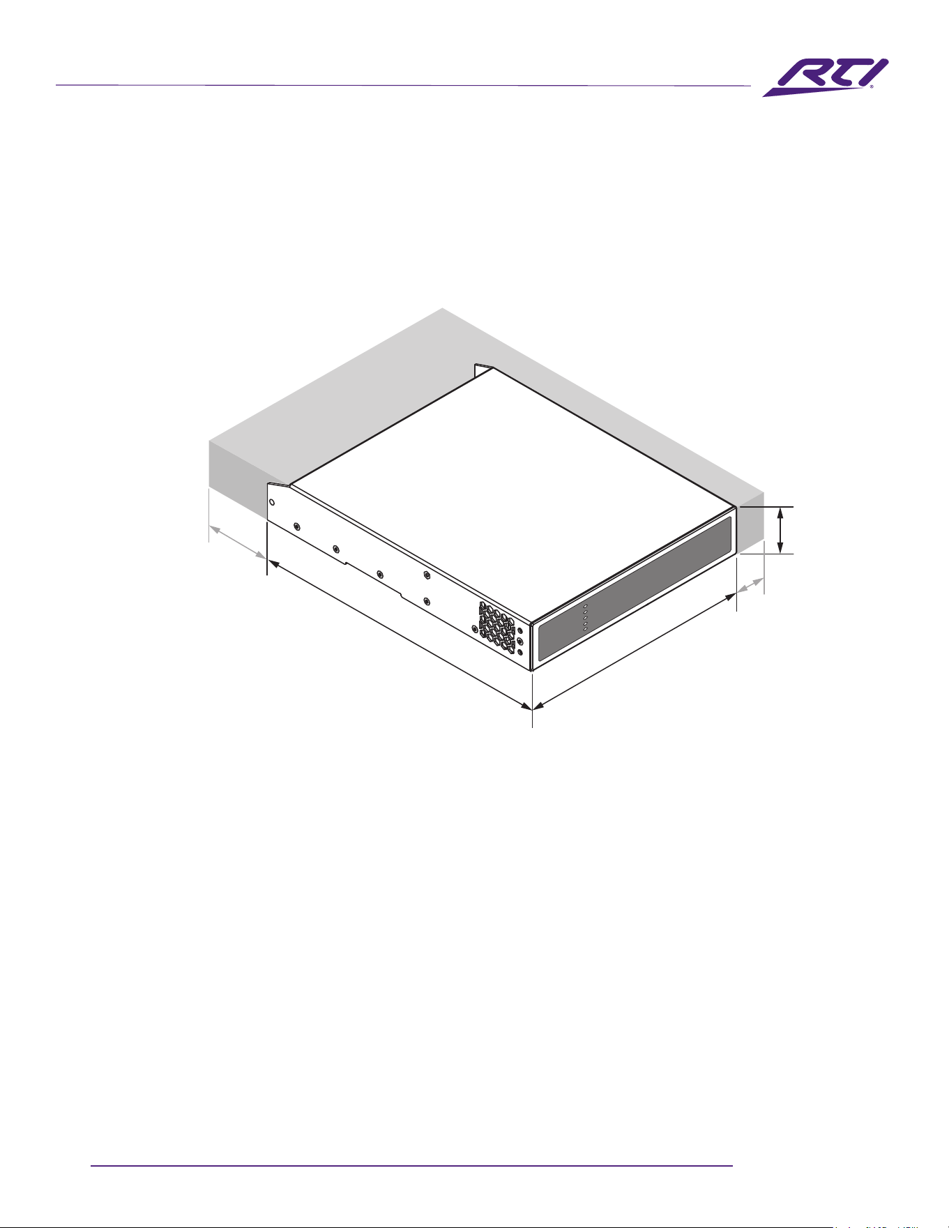
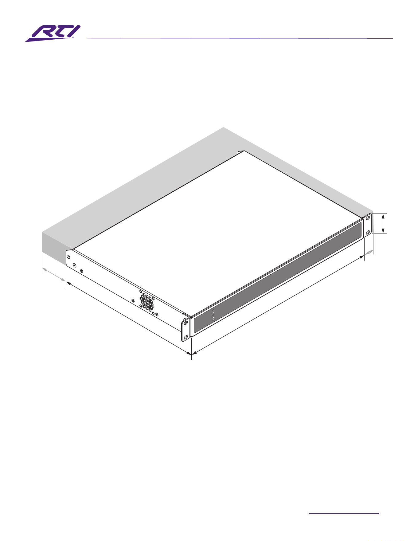
2.3 Dimensions
AMP-4-125andAMP-8-125dimensionsandfeatures
areillustratedinDiagrams2Aand2B.Theampliers
areprimarilyintendedforinstallationinanequipment
rack but in some cases can also be under-desk or wall
mounted,orusedfreestanding.Theyarefan-cooledand
must be installed such that ventilation apertures are not
obstructed.
2.4 Firmware
Thismanualdescribesthefeatures,functionsanduser
interfaceoftheAMP-4-125andAMP-8-125running
Firmware Version 1.7.2.
Westronglyrecommendedthatthermware
versioninstalledintheamplierinuseischecked
initially,andregularlythereafter.Ifupdated
rmwareisavailable,theamplifiershouldbe
updated as a priority.
Thermwareinstalledintheamplifiercanbeidentifiedand
updated by selecting the Device option in the Control web
appSettingsMenu.Firmwareversionscanbechecked,and
rmwaredownloaded,fromtheAMP-4-125andAMP-8-125
website:http://www.rticontrol.com.Firmwareconbefound
athttps://www.rticontrol.com/dealer/rmware(Dealerlogin
isrequired).
3. Carton Contents
TheAMP-4-125andAMP-8-125ampliersareshippedin
acardboardcartoncontainingtheamplierunit,amains
cableappropriateforthesalesterritory,anaccessorypack,
andadocumentpack.Thefullcontentsislistedbelow.
•Amplierunit
• Mains power cable
• Input connector x 2 or 4
•GPIOsocketconnectorx1
•Outputconnectorx1,2or4
•Adhesiverubberfeetx4
•Setofrackears
• Document pack
5
www.rticontrol.com
AUDIO DISTRIBUTION
Diagram 2A
AMP-4-125 dimensions.
(Shadedareadenesventilationspace.)
44 mm
1.7 in
220 mm
8.7 in
213 mm
8.4 in
80 mm
3.1 in
25 mm
1.0 in
Technical Support: [email protected] - Customer Service: [email protected]
6
AUDIO DISTRIBUTION
80 mm
25 mm
Diagram 2B
AMP-8-125 dimensions.
(Shadedareadenesventilationspace.)
44 mm
319 mm
438 mm
7
www.rticontrol.com
AUDIO DISTRIBUTION
Installation
4. AMP-4-125 Half Rack Width Amplier
Installation
4.1 AMP-4-125 Mounting
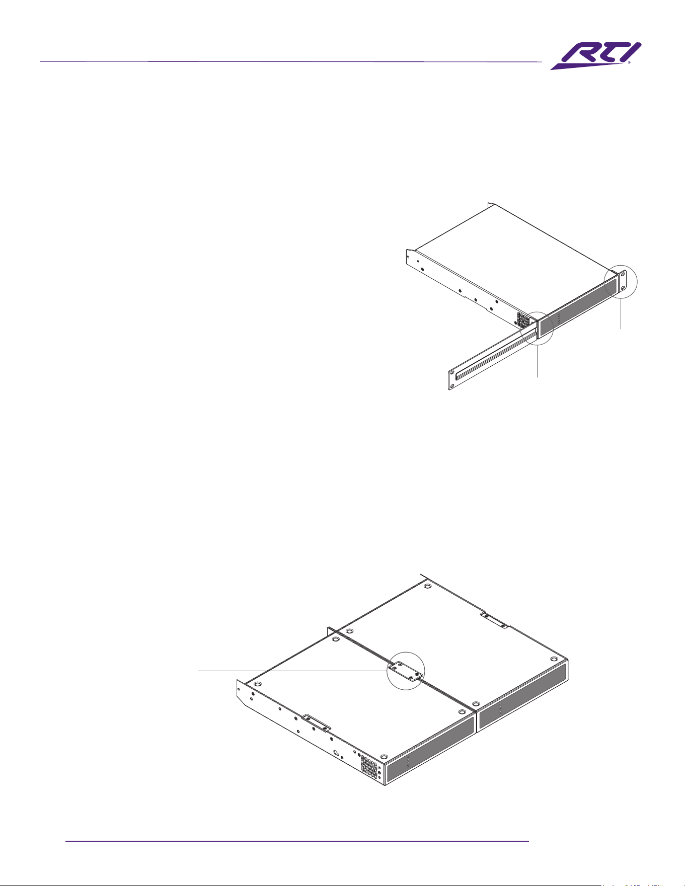
AMP-4-125 halfrackwidthampliersareshippedwithout
rackmounthardwareattachedbutcanbeconguredfor
rackinstallationusingonestandardrack‘ear’andone
half-rackextensionpieceasillustratedinDiagram4A.The
installationandequipmentrackshouldbeconguredto
provideappropriateventilationairowspacearoundthe
sidesandrearoftheamplier.Ventilationairflowspaceof
atleast25mm(1in)shouldbemaintainedalongatleast
onesideoftheamplieratalltimes.Ventilationapertures
arealsolocatedontherearpaneloftheamplierand
must not be obstructed. It is important to retain at least
80mm(3.1in)freespaceforairowbehindtheamplifier
rear panel.
Multiple AMP-4-125 halfrackwidthamplierscanalsobe
mechanically connected using an accessory connecting
plate.Diagram4Billustratestheuseofaconnectingplate.
A connection plate is included in the kit shown in Diagram
4B. Together with 2 x rack ears a connection plate enables
apairofamplierstobejoinedandinstalledinafull
width rack space.
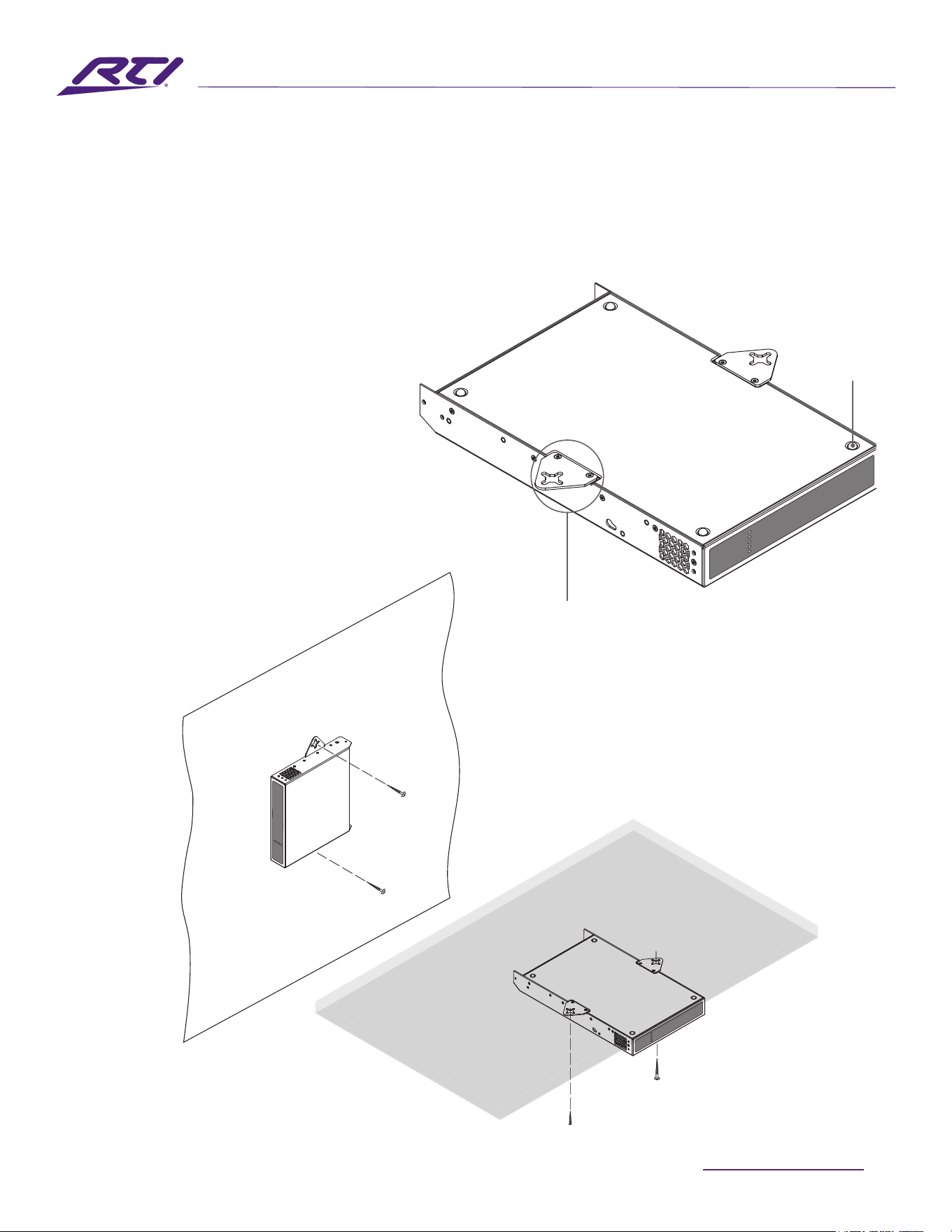
Diagram 4A
AMP-4-125
RackEar+Half-rackExtension.
RackEar+
2 x M4 x 8
countersunk
Half-rackExtension+
2 x M4 x 8 countersunk
ConnectionPlate+
4 x M3 x 6 countersunk
Diagram 4B
2 x AMP-4-125 with Connection Plate.
2 positions
Technical Support: [email protected] - Customer Service: [email protected]
8
AUDIO DISTRIBUTION
Installation
Diagram 4C
AMP-4-125
withdesk/wallMountingPlateandadhesivefeet.
2 positions and 4 positions.
Diagram 4D
AMP-4-125
wall and under-desk mount.
Note: Full rack width ampliers are not suitable for
under-desk or wall mount installation.
MountingPlate+
2 x M3 x 6 countersunk
Adhesive Foot
4 positions
4.2 Free-standing
Ifnotinstalledinanequipmentrack,theAMP-4-125amplier
canbeplacedfree-standingonaatsurface.Adhesiverubber
feetaresuppliedforthispurpose.
TheAMP-4-125ampliercanalsobeattachedtothe
undersideofdesksorwallmountedusingconnecting
platehardware.Theadhesiverubberfeetshould
also be used in these circumstances to minimise
thepossibilityofvibrationbetweentheamplier
andmountingsurface.Wallanddeskmountingis
illustrated in Diagrams 4C and 4D.
Itisimportantinanyfreestandinginstallationthat
airowthroughtheamplifier’ssidepanelmounted
fansandrearpanelventilationaperturesisnot
compromisedbyadjacentitems.Atleast80mmof
freespacebehindtheamplierand25mmalongat
least one side should be retained at all times.
9
www.rticontrol.com
AUDIO DISTRIBUTION
Installation
5. AMP-8-125 Full Rack Width Amplier
Installation
Note:FullrackwidthAMP-8-125isintendedforrackmount
orfree-standinginstallationonly.
5.1 Rack Mounting
TheAMP-8-125fullrackwidthamplierissuppliedwith
rackearstted.Theinstallationandequipmentrack
shouldbeconguredtoprovideappropriateventilation
airowspacearoundthesidesandrearoftheamplifier.
Ventilationairowspaceofatleast25mm(1in)shouldbe
maintainedalongatleastonesideoftheamplieratall
times. Ventilation apertures are also located on the rear
paneloftheamplierandmustnotbeobstructed.Itis
importanttoretainatleast80mm(3.1in)freespacefor
airowbehindtheamplifierrearpanel.
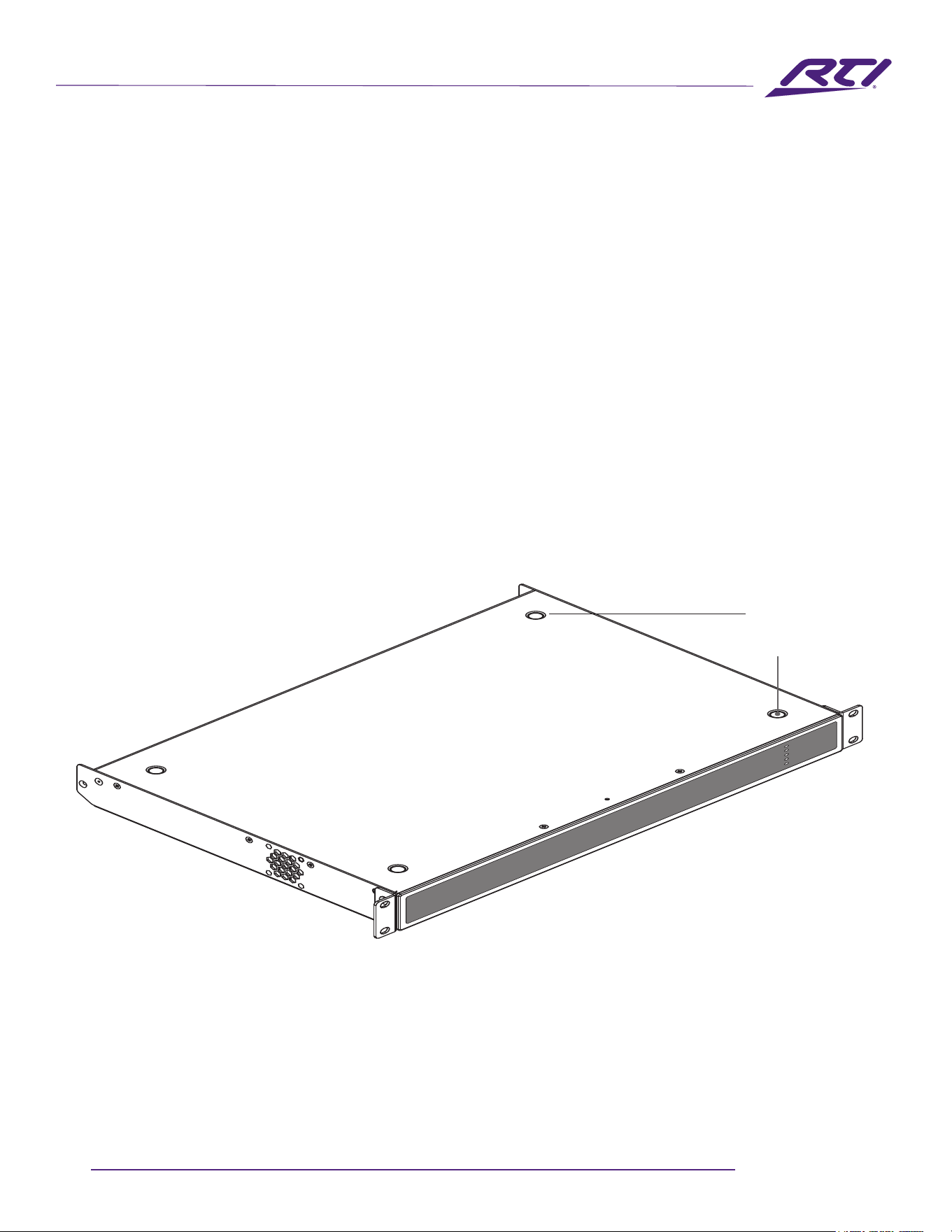
Diagram 5A
AMP-8-125
Adhesivefeet
5.2 Free-standing
Ifnotinstalledinanequipmentrack,theAMP-8-125fullrack
widthampliercanbeplacedfree-standingonaflatsurface.
Adhesiverubberfeetaresuppliedforthispurpose.Diagram
5Aillustratestheadhesivefootlocations.
Adhesive Foot
4 positions

Technical Support: [email protected] - Customer Service: [email protected]
10
AUDIO DISTRIBUTION
Conguration
6. Conguration
Beforemakinginput,outputandGPIOconnections,aninitial
AMP-4-125orAMP-8-125amplierconfigurationshouldbe
established.Itisparticularlyimportantthattheamplier
outputformatisconguredappropriatelyforthespeakers
that are to be connected.
CongurationrequiresthatAMP-4-125andAMP-8-125
ampliersareconnectedtomainspowerandnetwork
services.Theseconnectionsaredescribedinthefollowing
two sections.
6.1 Mains Power Connection
AMP-4-125andAMP-8-125ampliersincorporateapower
factorcorrectedpowersupplyandcanbeusedwithmains
inputvoltagefrom100VACto240VAC,50/60Hz.Usethe
mainscablesuppliedwiththeamplierandconnectittoa
switched mains supply.
AMP-4-125andAMP-8-125ampliershavenomainspower
switch and are operational as soon as mains power is
connected.
6.2 Network Services
AMP-4-125andAMP-8-125ampliersareconfiguredviaa
webpage.Beforethecongurationmenuscanbeaccessed,
theamplier(s)mustbeconnectedtothesameTCP/IP
network as the computer or mobile device that is to be used
forcongurationaccess.
6.2.1Wired(Ethernet)NetworkConnection
ToconnecttheampliertoaTCP/IPnetworkusingawired
connection(Ethernet)followthestepsbelow.
1.UseanEthernetcabletoconnecttheamplierrrearpanel
NetworkControlsocket(uppersocket)toafreesocketona
network router or switch.
2.Connecttheampliertomainspowerusingthesupplied
mainscable.WaitforthefrontpanelNetworkindicatorto
illuminategreentoindicatethattheamplierhasnetwork
connectivity.
3.TheAMP-4-125andAMP-8-125ampliersaresettoDHCP
bydefault.Thenetworkrouterwillautomaticallyassignthe
amplieranIPaddress.Anetworkscanningapplicationcan
beusedifrequiredtoidentifytheamplier’sIPaddress.
4.Openawebbrowserpageandentertheamplier’sIP
address.Theamplier’sControlWebAppinterfacewillopen
toenableamplierconfigurationasrequired.
Note: If the amplier is power cycled while using DHCP, it is
possible that the network router will assign it a dierent IP address,
leaving its conguration page inaccessible via the previous address.
If this occurs, a network scanning app can be used to identify the
new IP address. DHCP and Fixed IP address option settings can be
found in the Settings Tab menu described in Section 6.3. It’s recom-
mended to use a MAC reservation in the network router.
6.2.2 Wireless (WiFi) Network Connection
ToconnectaAMP-4-125orAMP-8-125ampliertoaTCP/IP
networkusingawirelessconnection(WiFi)followthesteps
below.
1.Withtheamplierconnectedtomainspower,waitforthe
frontpanelWiFiindicatortoilluminategreen.
2.Useamobile,laptopordesktopdevicetosearchforavailable
WiFi networks. Connect to the AMP-4-125 or AMP-8-125
(productserialnumber)’usingthepassword,‘password’.The
amplierserialnumbercanbefoundonitsrearpanel.
3. Open a computer or mobile device web browser and enter
theIPaddress:192.168.4.1.TheControlWebAppinterfacewill
opentoenableamplierconfigurationasrequired.
4.SelecttheWebAppSettingsTabfollowedbyWiFi>WiFiMode
>Clienttoconguretheamplifiertoconnecttotherequired
WiFI network. The WiFi network name and password will be
required.
It is strongly recommended that the amplier Access
Point WiFi password is changed following initial wireless
connection.
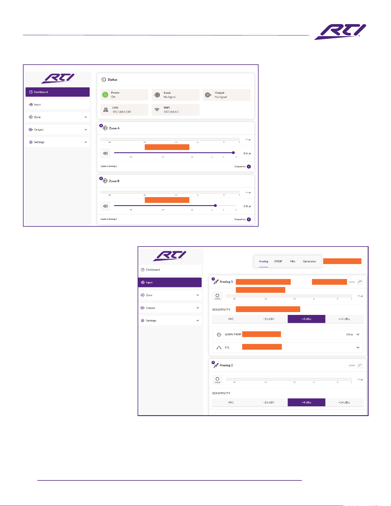
6.3 Conguration Menus
Opening a web browser that is network connected to the
amplierinitiallydisplaystheControlWebAppDashboard
illustratedinDiagram6A.TheDashboardisthe‘home’page
fromwhichallothercongurationoptionscanbeaccessed.
TheDashboarddisplaystheamplierstatus,outputzonesand
thecongurationmenutabs.Italsoenablesimmediateaccess
tozonevolumecontrolThefunctionsavailableundereach
congurationmenutabaredescribedinthefollowingsections.
11
www.rticontrol.com
AUDIO DISTRIBUTION
Conguration
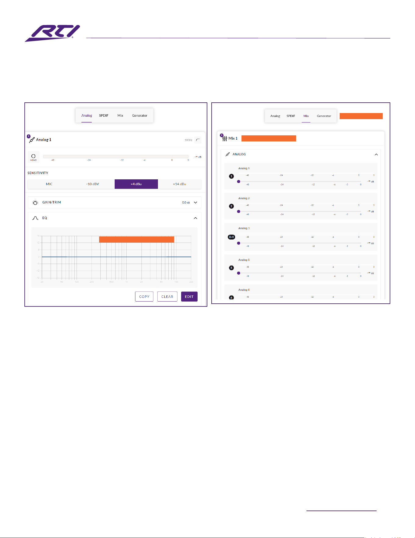
6.3.1 Input Tab
TheInputTab(Diagram6B)providesthe
followingcongurationparametersfor
eachamplierinputchannel:
• Input name
• Mono/Stereo selection
• Input sensitivity
• High-passlter
• Gaintrim
• Fivebandequalization
The Input Tab also enables input signals
tobemixedandroutedtospecic
amplierzones.Themixfunctionenables
anyamplierinput,includingstereoor
splitmonoS/PDIFinputs,tobegrouped
with any other input or inputs to create
multiplepredenedmixes.
Note: When adjusting the input gain, the
input level display should remain green. If it displays red, reduce the
input gain.
Diagram 6A
CongurationDashboarddisplay
Diagram 6B
Input Tab display
(onlytwoinputsshown)
Adjustzonevolume
Adjustzonevolume
Select input type
Input name - type to edit
Select mono or stereo
Select input sensitivity option
Adjustinputgain
OpenEQwindow
High-passlter
Technical Support: [email protected] - Customer Service: [email protected]
12
AUDIO DISTRIBUTION
6.3.2 Zone Tab
TheZoneTabenablesinstallationzonestobedenedand
named,andprovidesaccesstofurthersub-menus.Zones
mightbebarorrestaurantareasforexample,ordierent
roomsinahome.ForallZoneTabmenus,theinstallation
zoneundercongurationisselectedbyhighlightingoneof
thezoneidentiers(AtoHdependingonamplifieroutput
count)atthetopofthedisplay.Diagram6Eand6Fillustrate
theZoneTabandZoneSourcemenudisplays.
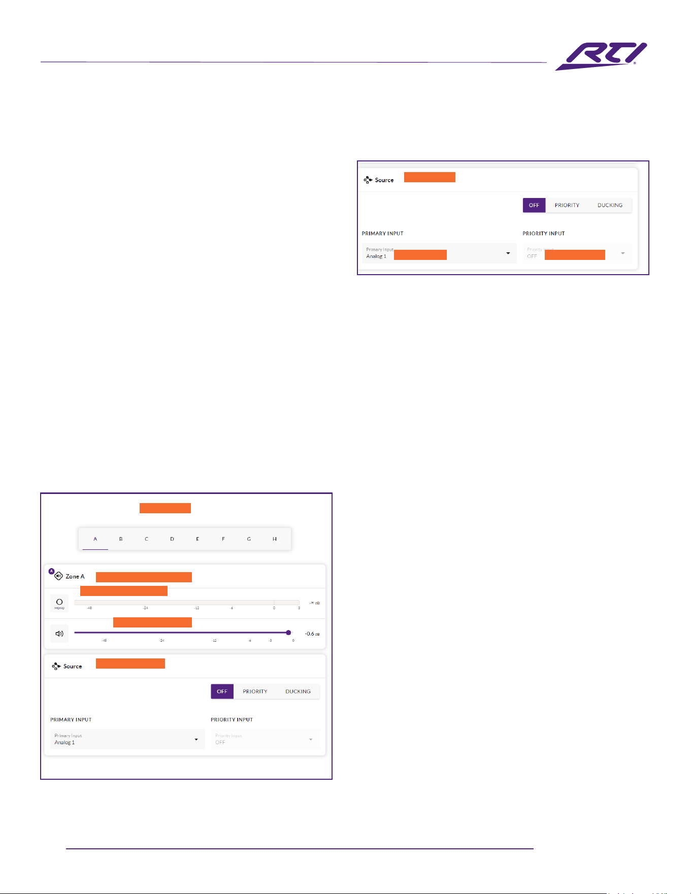
• TheSourcemenuenablesinputstobeassignedtozones
andInputPriorityorInputDuckingtobecongured.The
InputPriorityfunctionenablesanalternativeinputto
replaceandmutetheinputprimarilyroutedtothezone
undercongurationwhenthealternativeinputexceedsa
preset level.
Diagram 6C
InputEQdisplay
Note: The number of individual mixes possible is equal to the
number of amplier analog outputs (two outputs enables two
mixes, four outputs enables four mixes, eight outputs enables
eight mixes). Note: Mix inputs are muted by default with their
level adjustment sliders set to zero. Mix operations take place
following high-pass lter, input equalization and mono/stereo
selection.
Apinknoiseorsinewaveaudiosignalgenerator,
appropriateforaudiosystemtestingandsetup,canalso
beenabled,disabled,andadjustedforgainandfrequency
viatheInputTab.Diagrams6B,6C,and6Dillustratethe
InputTab,InputEQandInputMixdisplaysrespectively.
Conguration
Diagram 6D
Input Mix display
SelectEDITtoapplyrequiredEQ
Slectmicfunction
Mix name - type to edit
13
www.rticontrol.com
AUDIO DISTRIBUTION
Selectzone
Diagram 6E
ZoneTabdisplay
Conguration
The Input Ducking functionenablesanalternativeinput
to replace and attenuate the input primarily routed to
thezoneundercongurationwhenthealternativeinput
exceeds a preset level.
Note: Input Priority and Input Ducking parameters can be
either set to default values or their Threshold, Attack, Hold
and Release values set as required. Input Priority can also be
set to ignore the volume level set for the specied zone and
take a specic override volume.
• The Volume menu allows minimum and maximum
zonevolumelimitstobeset,andenablesexternal
GPIOvolumecontroltobeappliedtoindividualzones.
TheGPIOcongurationmenucanbefoundunder
theSettingsTab,andnotesonconnectinganexternal
volumecontrolviatheGPIOinterfacecanbefoundin
Section6.5ofthismanual.
Diagram 6F
ZoneSource menu display
Note: If an amplier is controlled via a third-party control system
API, volume level limits set via the Input Tab will not apply.
• TheRestrictionsmenuenableszoneinputsorinputmixes
toberestrictedfromroutingtoparticularzones.
Note: Routing restrictions cannot be applied to priority zone
inputs.
Note: If an amplier is controlled via a third-party control system
API, input routing restrictions set via the Input Tab will not
apply.
• TheCompressoroptionenablesdefaultorcustomsignal
compressiontobeappliedtoindividualzones.
Note: Compression can be useful to reduce the volume
dierence between loud and quiet audio material. The lower the
compression threshold is set, the more the dierence between
loud and soft will be reduced. The overall zone volume may
need to be increased when compression is used. The default
compression parameters are appropriate for most installations.
Selectzone
Select input Select priority
Zonename-typetoedit
Select mono or stereo
Selectzoneinput
Adjustzonevolume
Technical Support: [email protected] - Customer Service: [email protected]
14
AUDIO DISTRIBUTION
Conguration
Diagram 6H
Speaker Preset Parameters
Diagram 6G
Output Tab display
6.3.3 Output Tab
TheOutputTab(Diagram6G)enablesamplieroutputsto
benamed,linkedtozones,andprovidesaccesstoDelay,
RoomEqualizerandSpeakerPresetmenus.Diagram6H
illustrates the Output Tab display.
ForallOutputTabmenus,theamplieroutputunder
congurationisselectedbyhighlightingoneoftheoutput
identiersatthetopofthedisplay.
Note:Thenumberofindividualoutputsavailablefor
congurationwilldependontheinput,zone,andoutput
modeconguration.Thediagramsfollowingillistrateafour
outputamplier.
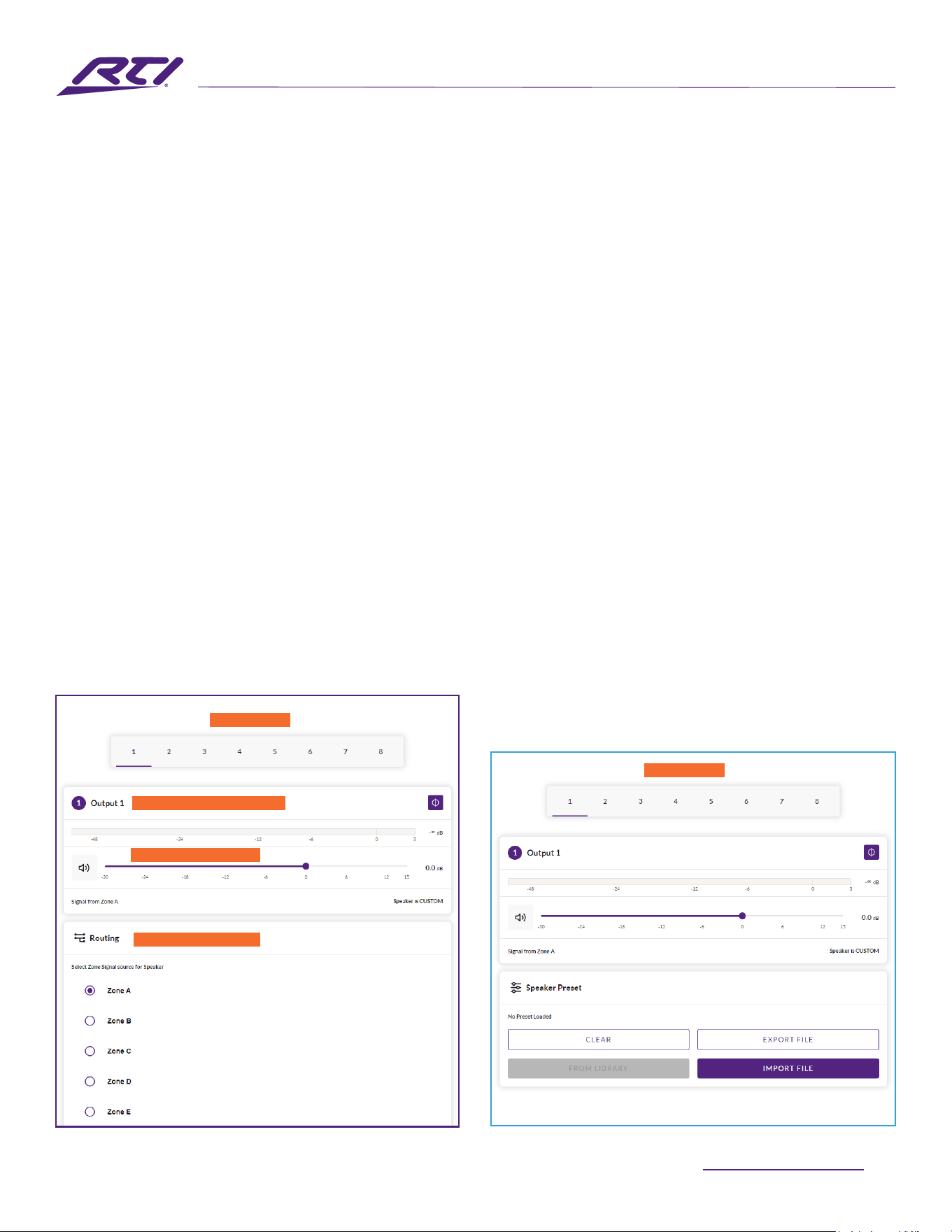
• TheRoutingmenuenableszonestobeassignedto
amplieroutputs.
Note:Routingforzonesspeciedasstereowill
automaticallyoerthreeoutputoptions:leftchannel,
right channel or summed mono. The summed mono signal
canpotentiallybeusedtodriveamonosubwooferora
70/100V mono speaker line.
• The Delay menu enables delay to be applied to
individualamplieroutputs.
• TheEqualizermenuenablesparametricequalizationtobe
appliedtoindividualamplieroutputs.Equalizersettings
conguredforoneamplifieroutputcanbecopiedand
applied to other outputs.
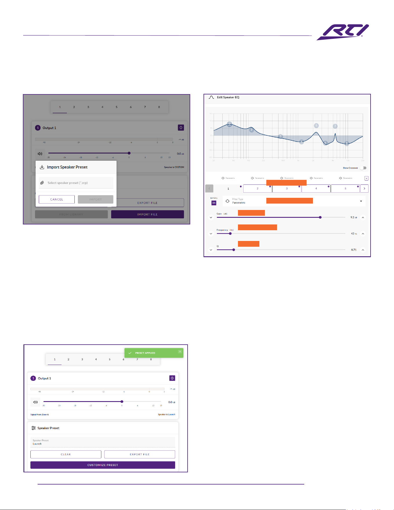
• TheSpeakerPresetmenuenablesasetofspeaker
parameterstobeadjusted,andpresetcongurationsto
becreated,exported,imported,orcleared.
Speaker Presets can be simply applied to the selected
amplieroutputorimported,chosenfromalibrary,
exportedorcleared.Thepresetcongurationscaninclude
anyoralloftheparametersdescribedinSection6.3.4and
canbelockedtopreventinadvertentmodication.Diagrams
6I,6J,and6Killustratetheapplicationofspeaker
presets.
SpeakerPresetdataprovidedbythirdpartiesforusewith
specicspeakerscanbeimportedandappliedtoamplifier
outputs.Toimportspeakerpresetparametersfollowthe
steps described below and illustrated in the diagrams.
1.SelecteithertheIMPORTPRESETFROMLIBRARYor
SELECTPRESETFROMFILEoptionfromtheSpeaker
Presetmenu.Ifnoimportoptionisvisible,select
CLEARtodeleteanyexistingspeakerpresetdata.
Output name - type to edit
Select output
Deneoutputrouting
Adjustgainifrequired
Select output
15
www.rticontrol.com
AUDIO DISTRIBUTION
Note: The SELECT PRESET FROM LIBRARY option will be
unavailable if no speaker preset libraries have been created.
Speaker preset library creation and management is described in
Section 6.3.5.
2.Selecttheappropriate‘.zcp’formatspeakerpreset
dataletoimportfromeitheraLibraryoracomputer
folder.Thepresetdatawillbeappliedtotheselected
amplieroutputassoonasthefileimportiscomplete.
3.
IftheSpeakerPresetdatarequiresmodicationitcanbe
customizedbyselectingtheCUSTOMIZEPRESEToption.
Diagram 6I
SpeakerPresetimportleselection
Conguration
Diagram 6J
Speaker Preset applied
Note: If an imported Speaker Preset data le includes locked
parameters, they will be unavailable for modication.
6.3.4 Speaker Preset Menu Parameters
• The Crossover & Gain preset menu enables high or
low-passcrossoverltersandgainadjustmenttobe
appliedtoindividualamplieroutputs.
• The Speaker EQ preset menu enables parametric
equalizationtobeappliedtoindividualamplier
outputs.
• The FIR presetmenuenablesFIR(FiniteImpulse
Response)basedequalizationltercoefficients
generatedbyexternalspeakermeasurementsoftware
tobeimportedandappliedtoindividualamplier
outputs.TheFIRlterhas512tapsat48kHz.
Note: FIR coecient les in either .csv or .txt format can be
imported.
Diagram 6K
SpeakerPresetparameteradjustment
EngageEQbands
Selectbandfunction
Adjustgain
Adjustfrequency
AdjustQ
Technical Support: [email protected] - Customer Service: [email protected]
16
AUDIO DISTRIBUTION
Conguration
Diagram 6L
Settings Tab menu
• The Driver Alignment preset menu enables delay to be
appliedtoindividualamplieroutputs.
• The Polarity presetmenuenablesthepolarityof
individualamplieroutputstobereversed.
• The Limiter preset menu enables signal limiting
tobeengagedorbypassedonindividualamplier
outputs.Cliplimiting,PeaklimitingandRMSlimiting
can be individually or collectively engaged. The Clip
limitingfunctionoersFastandNormalresponse
timeoptions.ThePeaklimitingfunctioncanbesetto
either Automatic or Manual parameter values. The
RMSLimiterhasdefaultparametervaluesthatcanbe
adjustedbuthasnoautomaticoption.
Note: In automatic mode, the peak limiter parameters adjust
automatically in response to Crossover & Gain high-pass lter
settings.
• The Output Mode preset menu enables individual
amplieroutputstobeswitchedofforconfiguredfor
Lo-ZorHi-Zmodes.InHi-Zmodes,ahigh-passlter
canalsobeconguredandappliedtotheoutput.
Thenumberofoutputsavailablewilldependonthe
ampliermodel,inputsetupandzonesetup.For
example,atwooutputamplierwillhavetwooutputs
availableifLo-Zmodeisselectedbutonlyoneoutput
availableifHi-Zmodeisselected.
Note: Use of a high-pass lter with Hi-Z mode loudspeakers
is useful to avoid the possibility of distortion caused by low
frequency line transformer saturation. Begin with the default
lter setting of 70Hz. If low frequency distortion is still audible,
increase the frequency setting one step at a time until the
distortion is no longer audible.
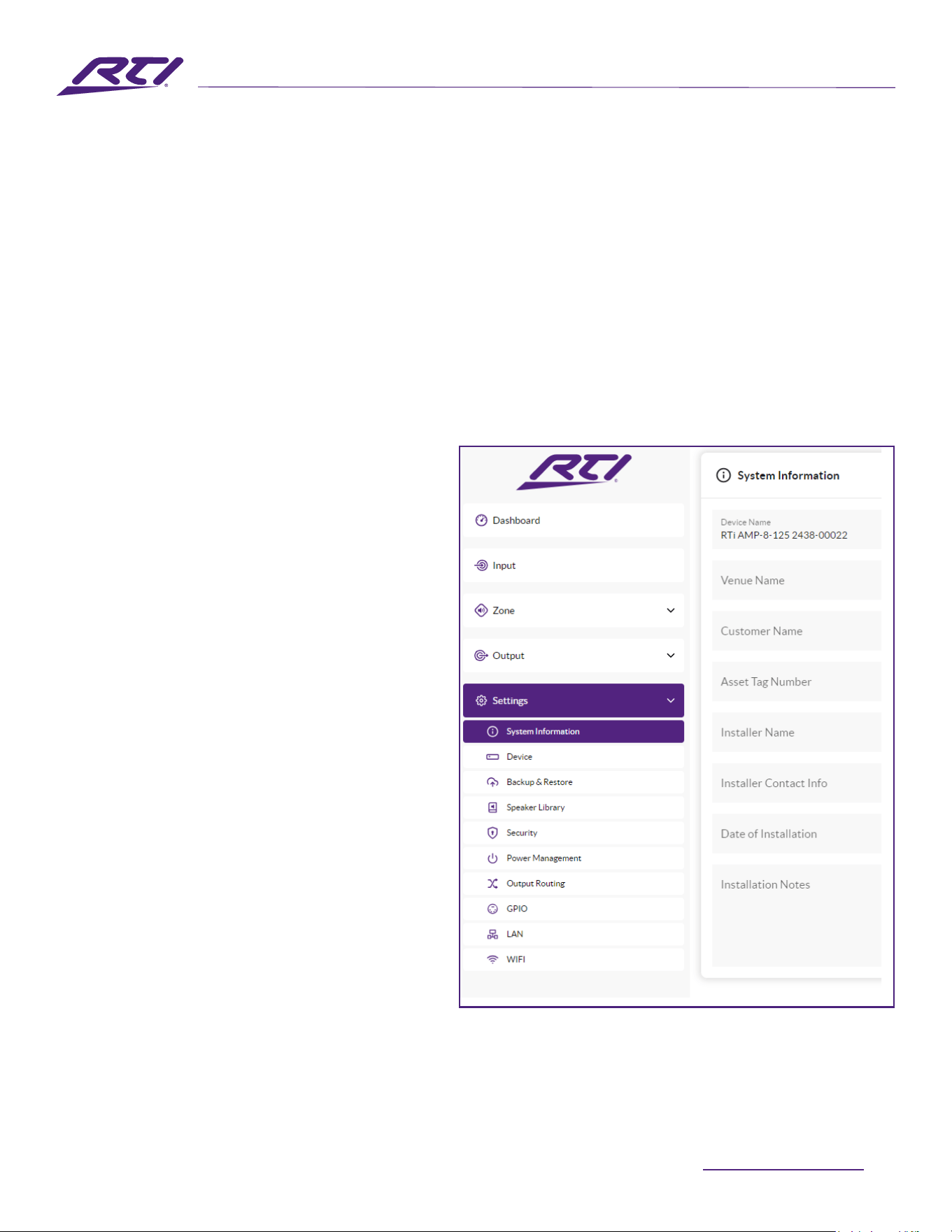
6.3.5 Settings Tab
TheSettingsTabenablesmiscellaneousampliersettings
tobeconguredandinstallationdatatoberecorded.
TheSettingsTabprovidesaccesstofurthersub-menus.
Diagram6LillustratestheSettings Tab.
• The System Informationmenuprovidestexteldsfor
therecordingofinstallationdata.TheDevice menu
recordsamplierspecificinformationsuchasthe
modelnumberandrmwareversion.
Armwareupdateroutineandidentifierbuttoncan
alsobefoundundertheDevicemenu.
• The Devicemenurecordsamplierspecificinformation
suchasthemodelnumberandrmwareversion.A
rmwareupdateroutineandidentifierbuttoncanalso
befoundundertheDevicemenu.
17
www.rticontrol.com
AUDIO DISTRIBUTION
Conguration
Diagram 6M
SpeakerLibraryCreationandManagement
• The Backup & Restore menuenablesamplier
congurationdatatobedownloadedtoanexternalarchive,
andenablespreviouslysavedcongurationfilestobe
uploadedandadoptedbythecurrentlyconnectedamplier.
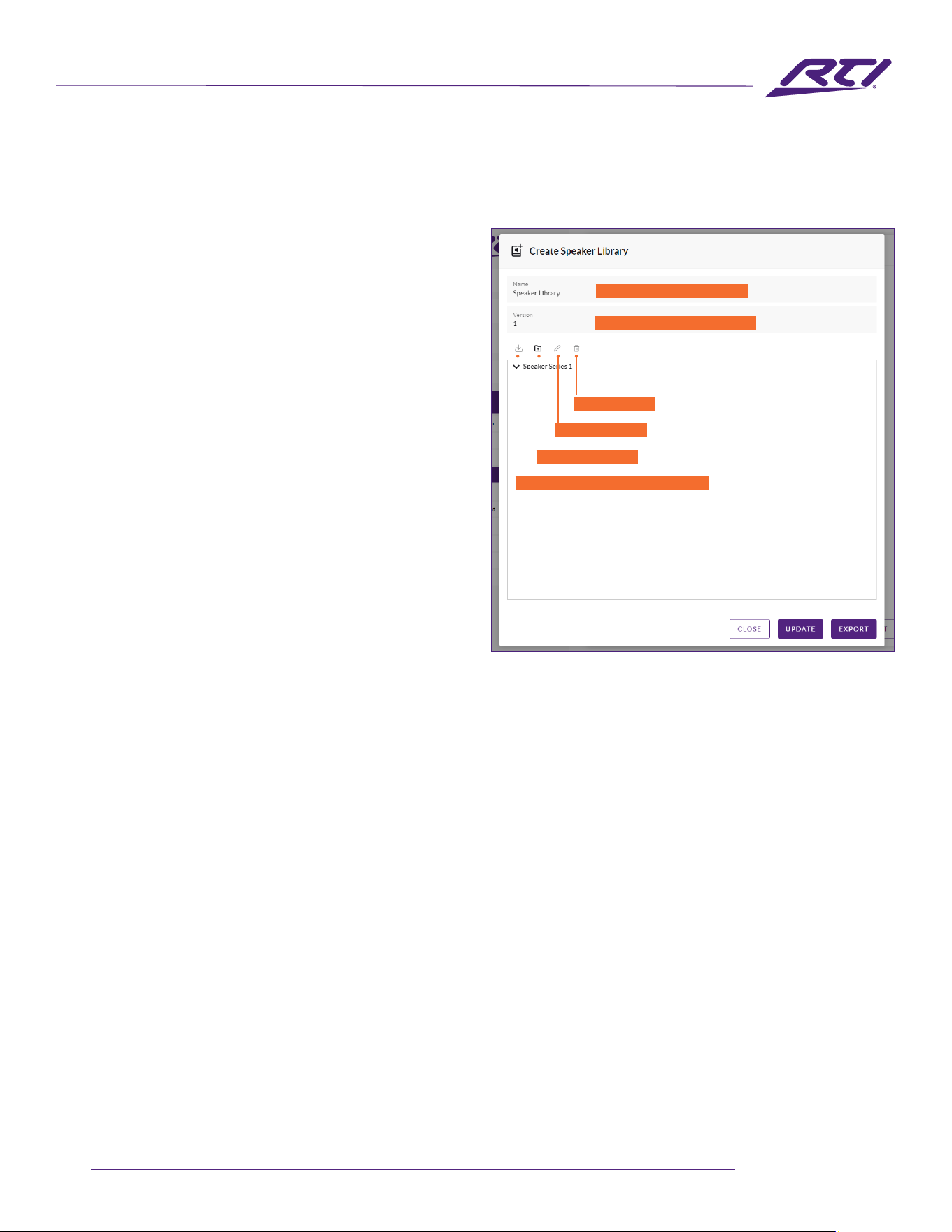
• The Speaker Librarymenuenablesmanagementof
speakerpresetlibraries.Existinglibrariesofspeakerpreset
les(.zcl)canbecreatedorimported,andexistinglibraries
editedorfullydeleted.Diagram6Millustratesthecreation
andmanagementofspeakerpresetlibraries.
• The Security menu enables a password to be set in order
toprotectagainstunauthorisedaccesstotheamplier
Control Web App. Password protection is particularly
importantwhenanamplierisconnectedtoawired
network as the a WiFi password is no longer required to
gain access to Control Web App.
Note: It is recommended that a Control Web App password is
dierent from that required to gain access to the amplier via WiFi.
• The Power Management menu enables various automatic
switch-on options to be engaged. The Power Management
menualsooerstimedStandbyandMutefunctions.
Note: In Eco mode the network is switched o during standby.
• The Output Routingmenuenablesspeciedinputsor
zonestoberoutedtotheamplierS/PDIFoutputs.The
outputlevelcanalsobeadjusted.
Anyzoneorinputcanberoutedtoeitherdigitaloutput,
includinginputsnotactivelyassignedtoazone.Primary
orpriorityinputstatusisimmaterial.Thespeciedinputis
alwaysroutedtothespeciedoutputtobeavailableforuse
by downstream devices.
Note: When a zone is selected for the digital S/PDIF output - the
output signal is variable.
Note: The digital output function is especially useful when
ampliers are to be daisy chained and a specic input; a central
paging mic, for example, is required to be routed to multiple
ampliers.
• The GPIOmenuenablescongurationofthemulti-purpose
GPIOinterfacepins.Adescriptionoftheindividualsettings
is detailed in AMP-4-125 and AMP-8-125 Control.
• The LANmenuenablescongurationandresetofthewired
network options and parameters.
• The WiFimenuenablescongurationandresetofthe
wireless network options and parameters.
6.4 Setup and Signal Routing
Thankstotheirnetworkbasedcongurationfeatures,the
AMP-4-125andAMP-8-125ampliersofferconsiderable
versatilityintermsofsources,signalrouting,installation
zonesandoutputmodes.Inputscanbefreelyassignedto
installationzones,andthosezonesassignedfreelytothe
availableamplieroutputsineitherLo-ZorHi-Zmodes.
Thisversatilityenables,forexample,oneamplier
simultaneouslytodrivebothLo-ZandHi-Zspeakers,orfor
dierentinputstoberoutedtodifferentoutputzones.
Thefollowingparagraphsdescribeandillustratethe
recommendedprocedureforconguringinput,zoneand
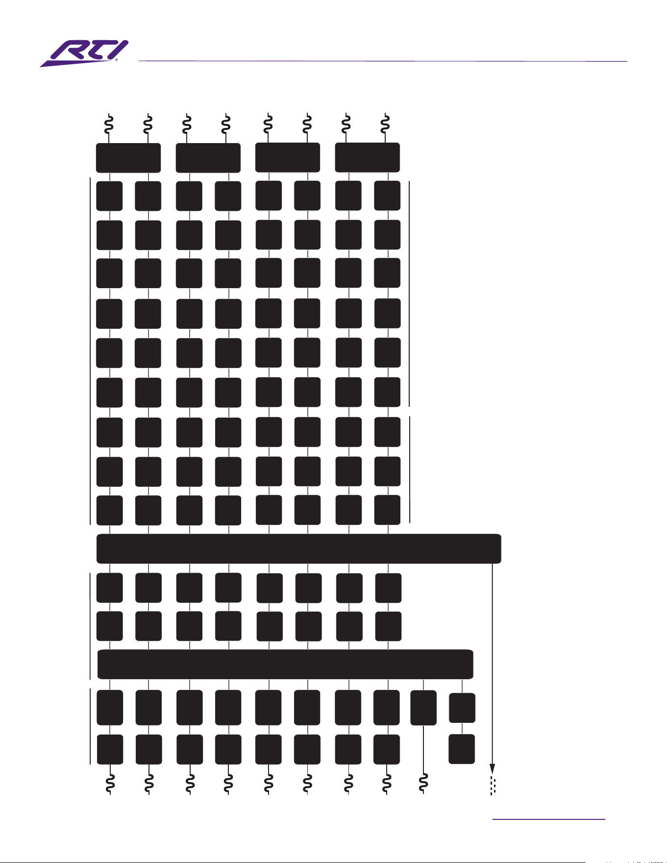
outputrouting.Ageneralsignalowschematicisalso
illustratedinDiagram6N.
Importpresetdata(.zcp)tolibrary
Creat new library
Rename library
Delete library
Libraryname-typetoedit
Libraryversion-typetoedit
Technical Support: [email protected] - Customer Service: [email protected]
18
AUDIO DISTRIBUTION
Conguration
Analog 3
Output
Matrix
Zones A - D
Outputs 1 - 8
Analog 2
Input
Sensitivity
Analog 1
Input
Gain
Input
Sensitivity
Input
Gain
Input
Sensitivity
Input
Gain
Analog 4
SPDIF (stereo)
SPDIF Out (any two input or zone signals).
Pink Noise
Gain
Delay
Level
Adjustment
Level
Adjustment
Level
Adjustment
Level
Adjustment
Compressor
Compressor
Compressor
Compressor
Level
Adjustment
Level
Adjustment
Level
Adjustment
Level
Adjustment
Compressor
Compressor
Compressor
Compressor
Delay
Delay
Delay
EQ
EQ
EQ
EQ
EQ
EQ
EQ
EQ
FIR
FIR
FIR
FIR
Polarity
Polarity
Polarity
Polarity
Limiter
BTL
Amplifier
2 x Low-Z
1 x Hi-Z
BTL
Amplifier
2 x Low-Z
1 x Hi-Z
Limiter
Limiter
Limiter
Driver
Alignment
Driver
Alignment
Driver
Alignment
Driver
Alignment
Crossover
Crossover
Crossover
Crossover
Gain Trim
Gain Trim
Gain Trim
Gain Trim
Input
Sensitivity
Input
Gain
Analog 7
Analog 6
Input
Sensitivity
Analog 5
Input
Gain
Input
Sensitivity
Input
Gain
Input
Sensitivity
Input
Gain
Analog 8
Input
Sensitivity
Input
Gain
Input
Selection
Input Setup
Zone Setup & Routing
Output Setup
Output 1
Output 2
Output 3
Output 4
Delay
Delay
Delay
Delay
EQ
EQ
EQ
EQ
EQ
EQ
EQ
EQ
FIR
FIR
FIR
FIR
Polarity
Polarity
Polarity
Polarity
Limiter
BTL
Amplifier
2 x Low-Z
1 x Hi-Z
BTL
Amplifier
2 x Low-Z
1 x Hi-Z
Limiter
Limiter
Limiter
Driver
Alignment
Driver
Alignment
Driver
Alignment
Driver
Alignment
Crossover
Crossover
Crossover
Crossover
Gain Trim
Gain Trim
Gain Trim
Gain Trim
Output 5
Output 6
Output 7
Output 8
Zone Adjustment Parameters
Speaker Preset Parameters
Input
Gain
Input
Gain
Input
Gain
Input
Gain
Diagram 6N
Signal Flow Schematic
(eightoutputamplier)

19
www.rticontrol.com
AUDIO DISTRIBUTION
Conguration
6.4.1 Input Setup
OpenthecongurationDashboardandselecttheInput
Tab. The Input Tab is shown in Diagram 6B.
• Toeditdefaultinputnamessimplyselectandtypein
theInputNameeld.
• Deneamonoorstereoinputbyselectingthe
appropriateoption.Deningastereoinputwillreduce
thetotalnumberofdiscreteinputsavailable.
• Selectaninputsensitivityoptionfromthedrop-down
menu:+14dB,+4dB,-10dBand‘microphone’options
areavailable.Generally,the+14dBor+4dBoptionsare
appropriatefor‘professionalaudio’sourcehardware
withbalancedoutputs,whilethe-10dBoptionismore
appropriatefor‘consumeraudio’sourcehardware
withunbalancedoutputs.The‘microphone’option
providesthesignicantlygreatersensitivityrequiredfor
microphones.
Note: Only dynamic microphones are suitable for connection.
Phantom power for condenser microphones is not provided.
• Ifnecessary,adjusttheinputgainusingtheslideror
up/downicons.Gainadjustmentisintendedtobe
usedforneoutputleveladjustmentfollowinginitial
use.Ifnecessary,adjusttheinputEQusingthe5band
equalizer.
6.4.2 Zone Setup & Routing
OpenthecongurationDashboardandselecttheZone
Tab.TheZoneTabisshowninDiagram6E.
• Selectthezonetobecongured.Thenumberofzones
availableandtheirchannelformat(stereoormono)will
dependontheampliermodel,inputsetupandoutput
mode(Lo-ZorHi-Z).
• TheAMP-4-125canhavethefollowingzones
congured:
•2xstereoLo-Zzones
•4xmonoLo-Zzones
•2xmonoHi-Z
•1xmonoHi-Z+1xstereoLo-Zzone
•1xmonoHi-Z+2xmonoLo-Zzones
• TheAMP-8-125canhavethefollowingzones
congured:
•4xstereoLo-Zzones
•8xmonoLo-Zzones
•4xmonoHi-Zorzones
•2xmonoHi-Zor+2xstereoLo-Zzone
•2xmonoHi-Zor+4xmonoLo-Zzones
Note:WhenconguredinHi-ZmodetheAMP-4-125and
AMP-8-125ampliersoperatein‘bridged’formatwhere
theoutputoftwochannelsiscombined.Thismeansthat
thenumberofoutputchannelsavailableinHi-Zmodeis
halfthatavailableinLo-Zmode.
Note: Mono signals might be mono at source, created though
combining the left and right channels of a stereo signal
(summed mono) or treating the left and right channels of a
stereo signal independently (split mono).
• NamezonesbytypingintheZoneNameeld.
• Adjustthezonevolumeifrequiredbyusingtheslider.
• Deneamonoorstereozonebyselectingthe
appropriateoption.Deningastereozonewillreduce
thetotalnumberoffurtherzonesavailable.
• Specifyaninputforthezonebyselectingfromthe
drop-downmenu.Selectingastereoinputforamono
zonewillautomaticallysumthestereochannelsto
mono.
6.5 GPIO Setup and Connection
TheAMP-4-1256andAMP-8-125provideaGPIOsocket
thatenablesremotecontrolofvolume,standby,muteand
triggerfunctions.TheGPIOconnectorpinfunctionsare
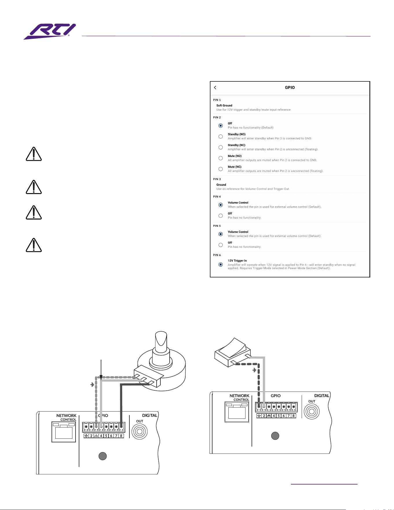
describedintheGPIOSettingsmenuillustratedinDiagram
6Q.TheconnectionofGPIObasedremotevolumecontrol
and standby/mute are illustrated in Diagram 6P and
Diagram6Qrespectively.
Technical Support: [email protected] - Customer Service: [email protected]
20
AUDIO DISTRIBUTION
Conguration
6.5 GPIO Setup and Connection
TheAMP-4-125andAMP-8-125ampliersprovideaGPIOsocket
thatenablesremotecontrolofvolume,standby,muteandtrigger
functions.TheGPIOconnectorpinfunctionsaredescribedinthe
GPIOSettingsmenuillustratedinDiagram6O.Theconnection
ofGPIObasedremotevolumecontrolandstandby/muteare
illustratedinDiagram6PandDiagram6Qrespectively.
Note:TheGPIOconnectormustnotbeusedforany
unintendedpurpose.Amplierdamagemayresultfrom
incorrectuseofGPIO.
Note:Shieldedcablemustbeusedwhenconnecting
standbyswitchesandpotentiometersviaGPIO.
Note:GPIOPin8hasalowoutputimpedanceandis
abletosupplyamaximumcurrentof10mA.
Note:GPIOPin1andPin3bothoergroundconnections:
Pin1isconnecteddirectlytotheamplierchassis.Pin3
is connected to the chassis via a 220 Ohm resistor. The
‘softground’connectionofPin3ispotentiallyusefulfor
managing ground loops that may cause audible hum.
Diagram 6O
GPIOSettingsMenu
Diagram 6P
Potentiometerconnectionsforremotevolume
controlviaGPIO.
Note: Diagram 7E illustrates
use of the GPIO connector.
Diagram 6Q
Connectionsforremotestandby/muteswitchviaGPIO.
Note: Diagram 7E illustrates use of the GPIO connector.
Connect Wiper to
Pin4,5,6,or7.
Switchopen(NO)orclosed
(NC)togglesStandby
or Mute depending on
options selected in the
GPIOSettingsMenu
Potentiometer
(>10kΩ)
Ground
+3V3
Ground
Standby/Mute
21
www.rticontrol.com
AUDIO DISTRIBUTION
Connections
7. Connections
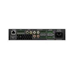
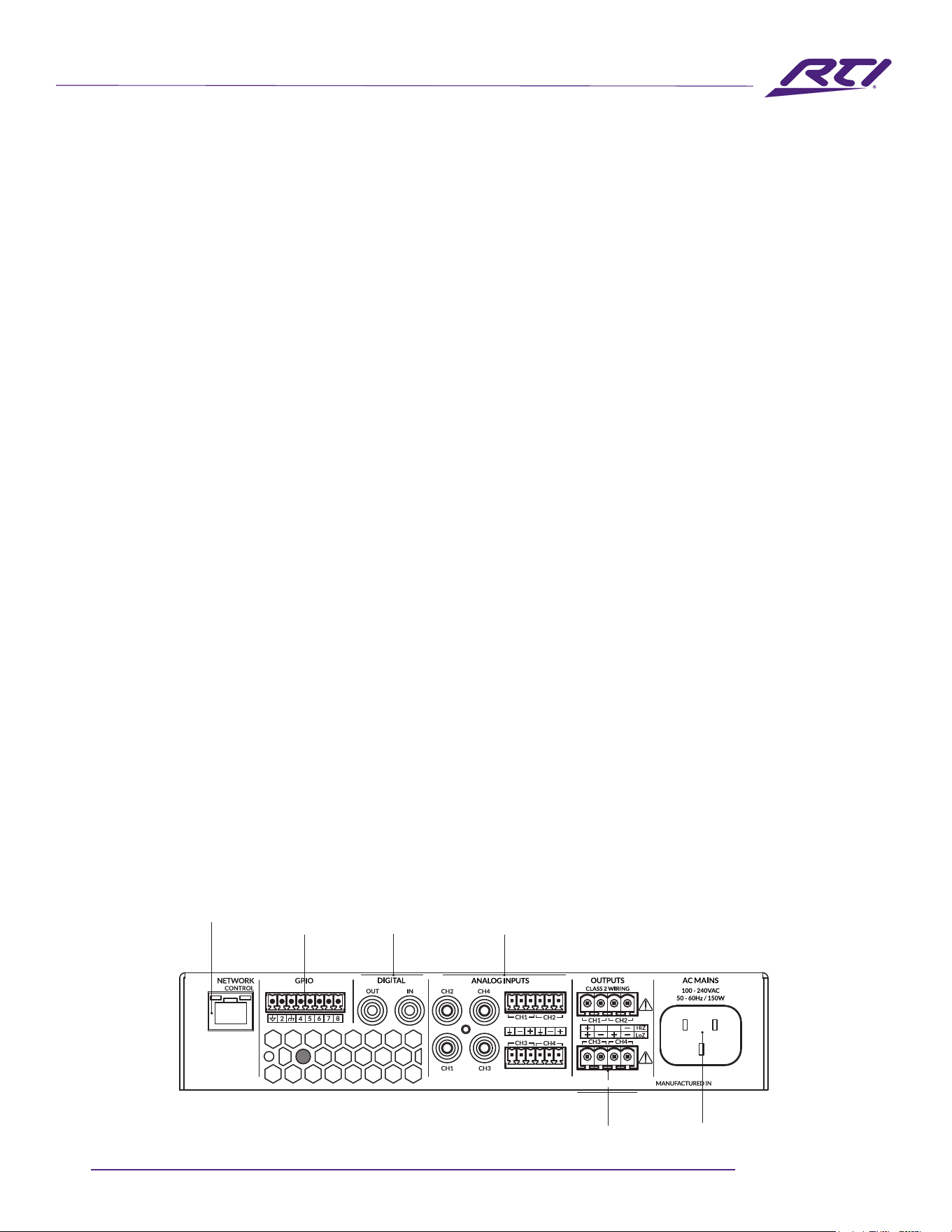
AMP-4-125 and AMP-8-125 rear panel connections
are illustrated in Diagrams 7A and 7B.
7.1 Mains Power Connection
Theseampliersincorporateapowerfactorcorrected
universal power supply and can be used with mains input
voltagefrom100VACto240VAC,50/60Hz.Usethemains
cablesuppliedwiththeamplier.
Theampliershavenomainspowerswitchandare
operationalassoonasmainspowerisconnected.Ensure
thatallsignal,GPIOandoutputconnectionsaremade
beforeconnectingtheampliertomainspower.
7.2 Input Connection
Bothampliermodelsprovidefourbalancedor
unbalanced analog audio inputs and a stereo S/PDIF digital
audio input. Any input channel can be routed to any output
channel.Inputroutingoptionscanbeconguredviathe
ampliernetworkinterface.SeeSection6ofthismanual.
Analog Inputs
Analoginputsareoflinelevelformatwithadefaultinput
sensitivityof+4dBu(fulloutputvoltageswing/sensitivity)
inalloutputmodes.Inputsignallevelsupto+24dBucan
be handled without input clipping. Input sensitivity options
canbesetviatheampliernetworkinterface.SeeSection
6ofthismanual.
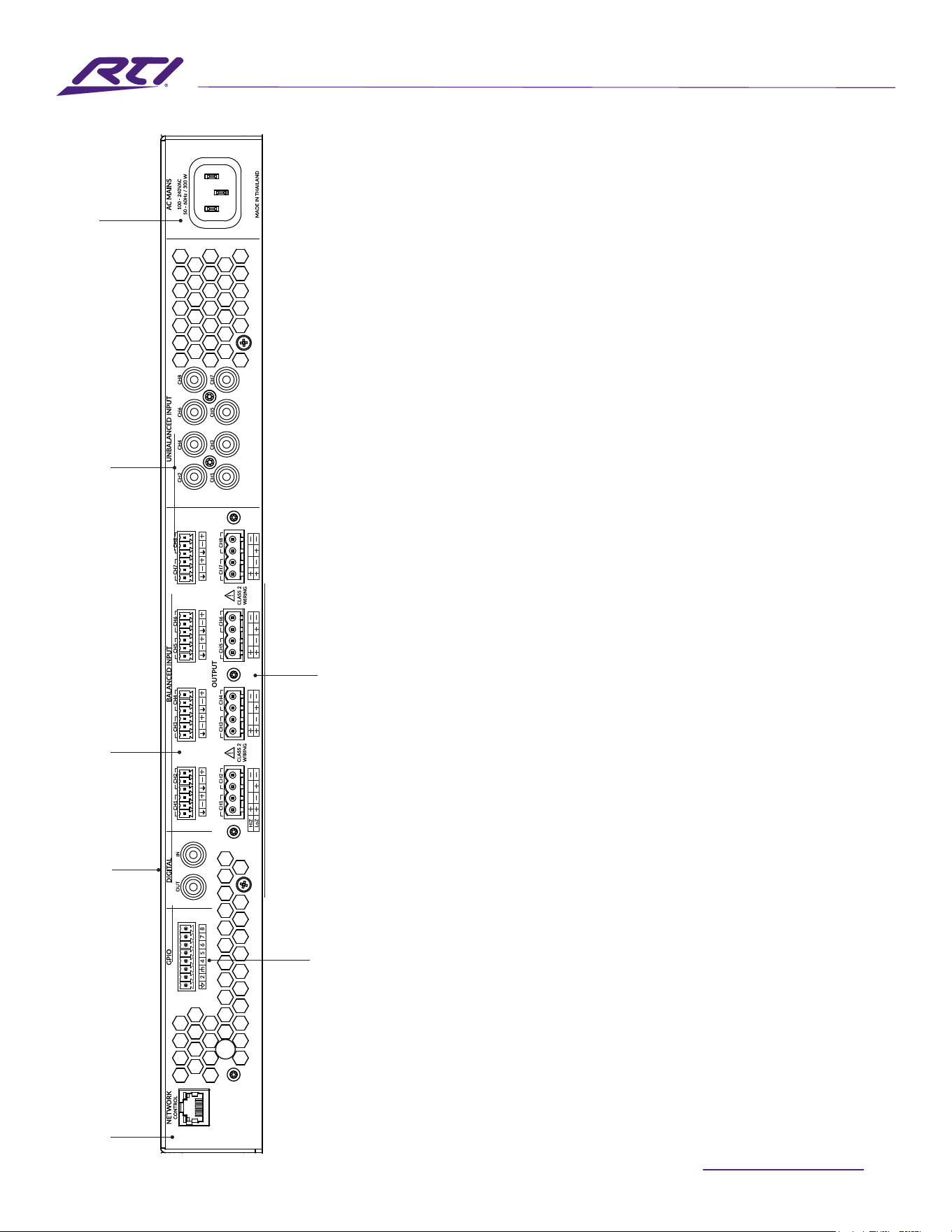
Diagram 7A
AMP-4-125 rear panel connections.
Note: Two output amplier model connection sockets dier
only in the deletion of channel 3 and channel 4 output.
Balancedinputconnectionstotheampliersaremade
viamale‘EuroBlock’connectors.Connectingcablestothe
suppliedfemaleinputconnectorsisillustratedinDiagram
7C.
Unbalancedinputconnectionstotheampliersaremade
via RCA phono sockets connected in parallel with the
balanced inputs.
Digital Outputs
Forbothampliers,S/PDIFstereodigitalaudiooutput
connections are made via a single RCA Phono socket. The
S/PDIFoutputsignalcanberoutedfromanyinputorzone
andisintendedtobeusedfordaisy-chainingmultiple
ampliers.
Note: See the Output Routing paragraphs of Section 6.3.3 for
more information on Digital Output conguration.
Note: 75Ω RCA Phono cables specically intended for digital
audio should always be used for S/PDIF connections. Standard
Phono cables can be used but may not result in optimal
performance.
Note: The S/PDIF output level is by default set at -10dB to
reduce the possibility of downstream input clipping.
Network Control Congurable
GPIO
Congurable
S/PDIF Audio I/O
Audio Inputs
Balanced: Euroblock
Unbalanced: RCA Phono
Congurable Speaker Outputs
Mains power input
THAILAND
Technical Support: [email protected] - Customer Service: [email protected]
22
AUDIO DISTRIBUTION
7.3 Output Connections
Outputconnectionsfromtheampliersareachievedvia
male‘EuroBlock’connectors.Ensurethatspeakerconnection
polarityiscorrectthroughouttheinstallation:
InthecaseofLo-Zspeakerconnections,positive(+)amplier
terminals should always be connected to positive speaker
terminalsandnegative(–)amplierterminalsalways
connected to negative speaker terminals.
InthecaseofHi-Zspeakerconnections,thetwospeaker
cable conductors should be connected between the positive
(+)terminalofOutput1andthenegativeterminal(-)of
Output2,andlikewiseforandadditionalHi-Zoutputs.
Outputmodeoptions(Lo-ZorHi-Z)canbeconguredviathe
ampliernetworkinterface.SeeSection6ofthismanual.
Connectingcablestothesuppliedfemaleoutputconnectoris
illustrated in Diagram 7D.
Connections
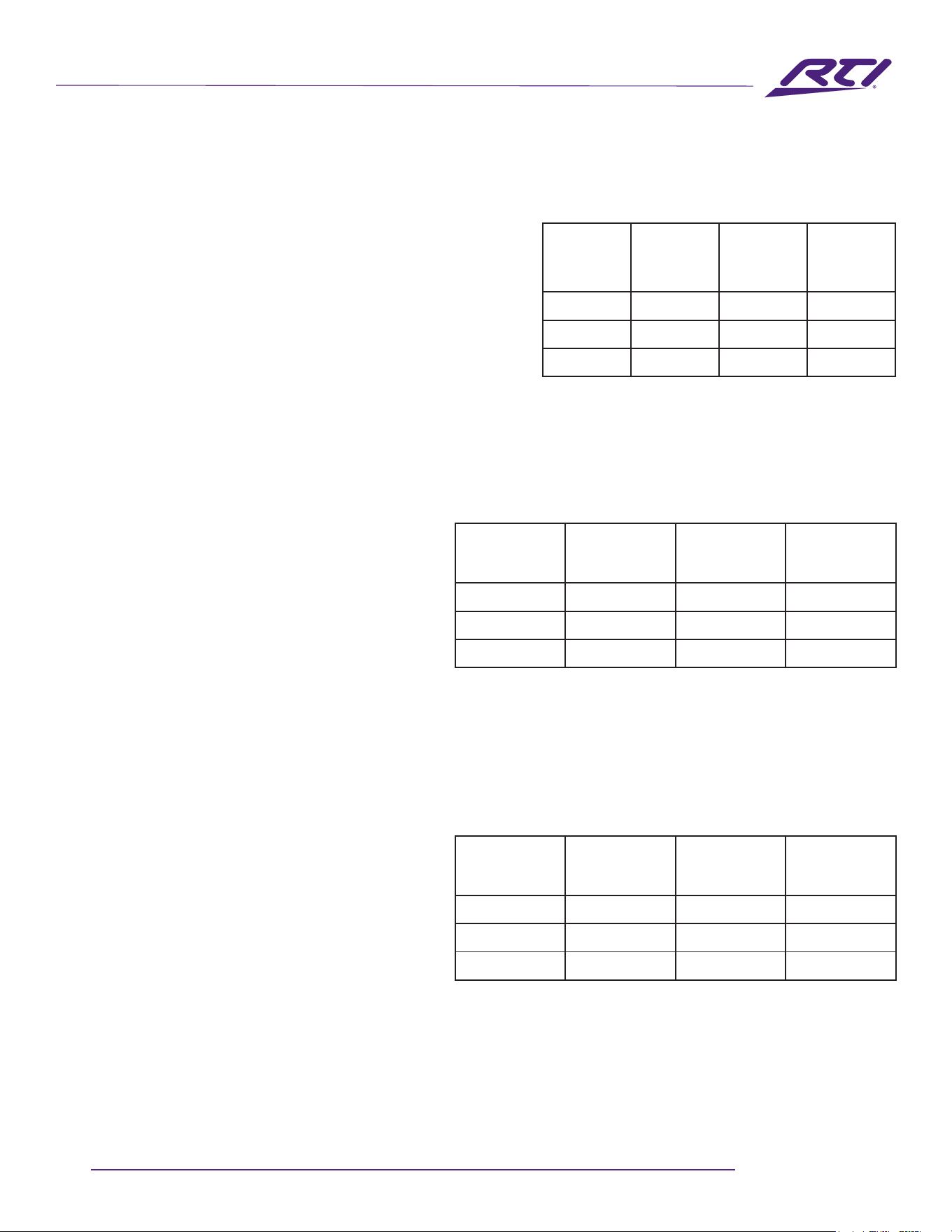
Diagram 7B
Full rack width
AMP-8-125 rear
panel connections.
Network
Congurable GPIO
Congurable
S/PDIF Audio
Audio Inputs
Balanced: Euroblock
Congurable Speaker Outputs
Audio Inputs
Unbalanced: RCA Phono
Mains
power input
23
www.rticontrol.com
AUDIO DISTRIBUTION
Connections
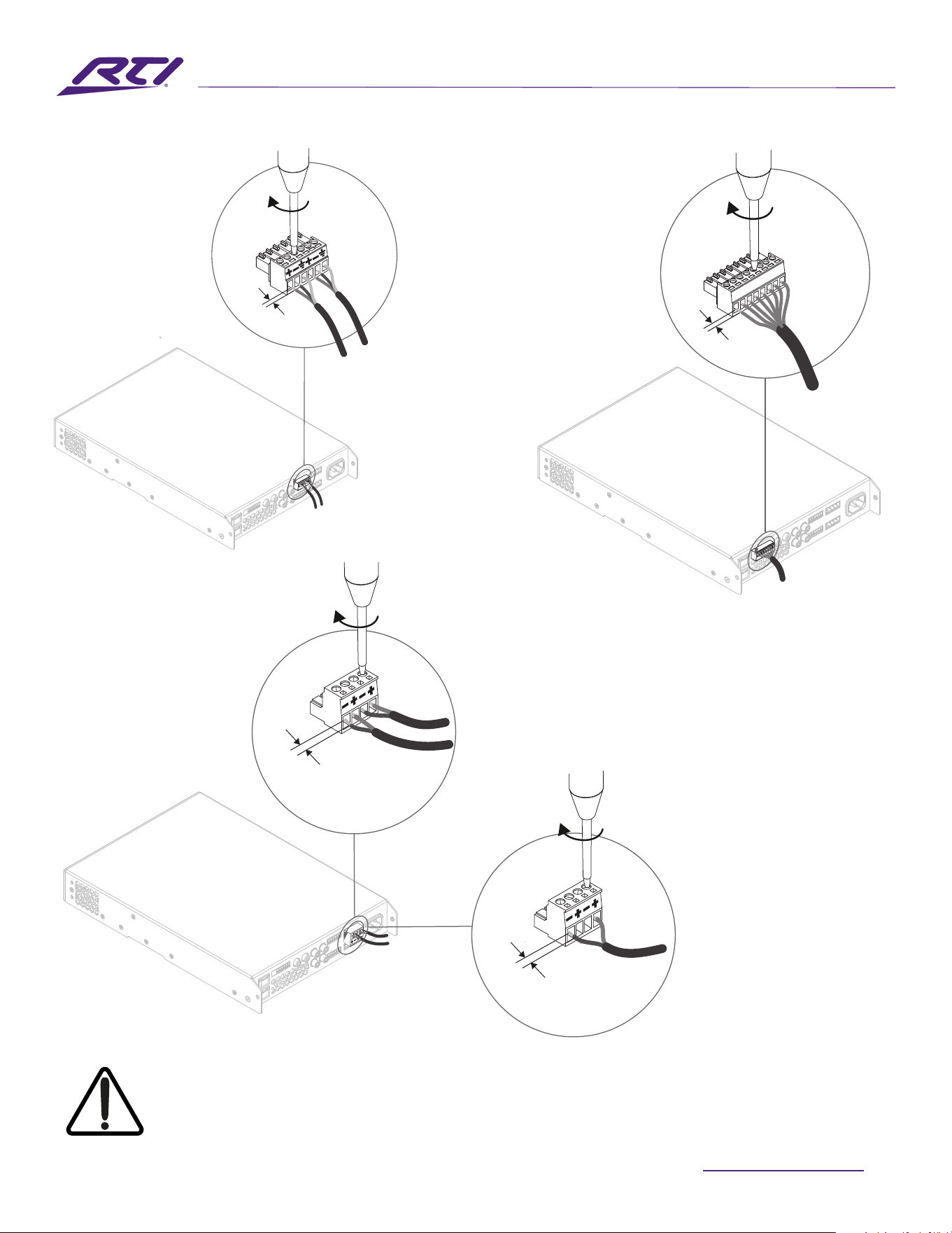
7.5 Speaker Cable Gauge
The speaker connection cable gauge should be chosen
appropriatelytoreectthetypeofinstallation.The
adjacenttablesspecifytheappropriatecablegauge
forlessthan0.5dBcablelosswithdierentinstallation
types and cable lengths.
7.5 GPIO Connections
IfanyGPIOfunctionalityisrequired,cableswillneed
tobeconnectedtothesuppliedGPIOconnector.
ConnectingcablestotheGPIOconnectorisillustrated
inDiagrams7E.
7.6 Network Connections
TheseampliersareTCP/IPnetworkconnecteddevices
thatareconguredviaawebpagebasedinterface.
Wired(Ethernet)andwireless(WiFi)connectionoptions
areavailable.ConnectingtheseamplierstoaTCP/
IPnetworkisdescribedinSection6ofthismanual.Ifa
wiredconnectionisused,connectanEthernetcableto
theamplierrearpanelNetworkControlsocket.
Cable Gauge Table
Lo-Zinstallations,0.5dBattenuation.4Ω&8Ωloads
Cable Gauge Table
70VHi-Zinstallations,1.0dBattenuation
20 speakers evenly distributed
Cable Gauge Table
100VHi-Zinstallations,1.0dBattenuation
20 speakers evenly distributed
Cable Cross
Section
(mm
2
)
CableGauge
(AWG)
Max Cable
Length
(Metres,4Ω
load)
Max Cable
Length
(Metres,8Ω
load)
0.75 ≈18 5 10
1.5 ≈16 10 20
2.5 ≈14 17 35
Cable Cross
Section
(mm
2
)
CableGauge
(AWG)
MaxCableLength
(Metres),
(125W/channel)
MaxCableLength
(Metres),
(250W/channel)
0.75 ≈18 90 45
1.5 ≈16 180 90
2.0 ≈14 <250 150
Cable Cross
Section
(mm
2
)
CableGauge
(AWG)
MaxCableLength
(Metres),
(125W/channel)
MaxCableLength
(Metres),
(250W/channel)
0.75 ≈18 190 90
1.5 ≈16 <250 180
2.0 ≈14 <250 <250
Note: Cable lengths should not exceed 250m.
Note: Cable lengths should not exceed 250m.
Technical Support: [email protected] - Customer Service: [email protected]
24
AUDIO DISTRIBUTION
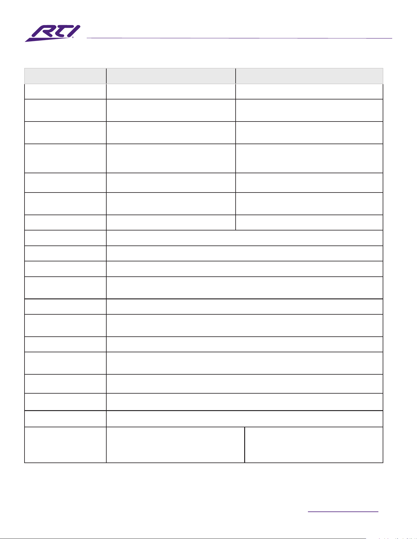
5 mm
5 mm
Low-Z Mode
Hi-Z Mode
5 mm
5 mm
Connections
Diagram 7C
Balanced analog input
cable connections.
Diagram 7D
Output cable connections.
Diagram 7E
GPIOcableconnections.
Theexclamationpointprintednexttotheoutputterminalsoftheampliersis,inadditiontotheCLASS2WIRING
text,intendedtoalertuserstotheriskofhazardousvoltages.Outputconnectorsthatcouldposeariskare
markedwiththeexclamationpoint.Donottouchtheoutputterminalswhiletheamplierisswitchedon.Make
allconnectionswiththeamplierswitchedoff.
Note:Input,outputandGPIOconnection
socketuseisthesameforfourandeight
channeloutputampliers.

25
www.rticontrol.com
AUDIO DISTRIBUTION
Operation
8. Operation
Onceallconnectionshavebeenmadeandconguration
optionsselected,theAMP-4-125orAMP-8-125isreadyfor
use.Ifaninputsignalabove-60dBispresentonanyinput,
thefrontpanelInputandStandbyindicatorswillilluminate
greentoindicatenormalamplieroperation.Audiowillbe
heardfromanyconnectedspeakers.
Note: The ampliers will not switch on from Standby Mode
unless an input signal is present, a network ‘ON’ command
is received, or an external standby switch (or 12V trigger) is
operated. Standby behaviour can be congured via the Power
Management menu of the Settings Tab.
Amplieroutputswillmuteifnoinputsignalispresentfor
5minutes,andtheamplierwillswitchautomaticallyto
StandbyModeifnosignalispresentonanyinputformore
than 15 minutes. Alternative standby and mute delay times
canselectedviatheSettingsTab.Ampliercoolingfanspeed
istemperaturecontrolled.Thefanwillswitchowhenthe
amplierentersstandbymode.
8.1 Front Panel Indicators
AMP-4-125andAMP-8-125amplierfrontpanelindicators
illuminatetoindicatethefollowingoperationalstates:
Status: O–Mainspowerdisconnected.
Green–Amplieroperational.
PulseGreen–StandbyMode.
Amber–GPIOtriggeredStandbyMode
Input: O–Noinputsignalpresent.
Green–Signalpresentononeormoreinputs.
Amber–Signallimiting/clippingononeormore
inputs.
Output: O–Nooutputsignalpresent.
Green–Signalpresentononeormoreoutputs.
Amber–Signallimiting/clippingononeormore
outputs.
Red–Oneormorechannelpairisin
overload/protection mode.
Network:O–NoEthernetnetworkdetected.
Green–Ethernetnetworkdetected.
WiFi: O–WiFidisabled.
Green–WiFienabled.
8.2 Automatic Power Sharing
TheAMP-4-125andAMP-8-125ampliersincorporate
apowersharingfeaturethatautomaticallysharesthe
totalpoweravailablefromtheamplier’sinternalpower
supplyacrosseachpairofoutputchannels.Ifonechannel
temporarilydemandsmorethantheamplier’scontinuous
powerratingwhileotherchannelisdemandingless,the
excesspoweravailablefromtheinternalpowersupplyis
automatically made available to the over-power channel.
Powersharingoptimisestheamplier’sabilitytodeliver
maximum power into dynamic loudspeaker loads when
playing music programme material.
8.3 Default Reset
Bothamplierscanbereturnedtotheirdefaultsettingsvia
either the Control Web App Settings Tab or the hardware
reset pinhole button. The reset pinhole button is located on
theundersidepaneloftheamplier.
Toresettheamplierusingthepinholebutton,followthe
stepsbelow:
•Disconnecttheamplierfrommainspower.
• Use an appropriate tool to press and hold the reset
pinhole button while simultaneously reconnecting mains
power.
•Continuetoholdtheresetpinholebuttonfor3seconds
astheamplierrestarts.
Theamplierwillrestartwithallsettingsattheirdefaultstate.
Anypreviouslyconguredsettingswillbedeleted.
Technical Support: [email protected] - Customer Service: [email protected]
26
AUDIO DISTRIBUTION
Specications
Model AMP-4-125 AMP-8-125
Total System Power 500 W 1000 W
OutputPower@4/8Ω 4 x 125 W 8 x 125 W
Output Power @ 70/100V* 2 x 250 W 4 x 250 W
Powershare(upto)
Across all channels**
2 x 250 W 4 x 250 W
Power Consumption 150W 300 W
Dimensions
44 x 220 x 319mm
(1.7x8.7x12.6in)
44 x 220 x 319mm
(1.7x17.3x12.6in)
Weight 2.8kg(6.2lbs) 3.8kg(8.4lbs)
Power Ratings 1% THD @ 120Vac and 230Vac
Output Circuitry UMAC™ClassD-fullbandwidthPWMmodulatorwithultra-lowdistortion
Output Voltage 70Vp/140Vpp(unloaded)//Bridged140Vp/280Vpp(unloaded)
SignalToNoise-Ratio >106dB(A-weighted,20Hz-20kHz,8Ωload)
THD+N(typical) <0.05%(20Hz-20kHz,8Ωload,3dBbelowratedpower)
Frequency Response 20Hz-20kHz(+0/-0.8dB(8Ωload,3dBbelowratedpower)
Protection Circuits Shortcircuit,DC,Undervoltage,Temperature,andOverloadprotection
Power Supply
UREC™universalmainsswitchmodepowersupplywithPowerFactorCorrection(PFC)andstandby
converter
Operating temperature 0-40°C
Operating Voltage/Frequency UniversalMains,100V-240V,50Hz-60Hz
Standby Consumption < 0.6W
Accessories
2x Rack ears
1x ½ rack plate extension
2x ½ rack mounting plates
2x Rear supports
2xRackears(tted)
2x Rear supports
*100Vlinemodeis@-1dB(≈90V)
** AMP-4-125 may only Powershare across Ch1-2 and Ch3-4
AMP-8-125mayonlyPowershareacrossCh1-2,Ch3-4,Ch5-6andCh7-8
27
www.rticontrol.com
AUDIO DISTRIBUTION
Rev 11/24
1/8th Full Power
Model
Load
(Ohms)
Power In
(W)
Power Out
(W)
Eciency
(%)
ThermalLoss
(W)
ThermalLoss
(BTU)
AMP-4-125 4 107 62.5 58.6 44.5 152
AMP-8-125 4 200 125 62.5 75 256
Standby and Idle
Model
Standby
(mW)
Idle @ 120V
(W)
Idle @ 120V
(BTU)
Idle @ 230V
(W)
Idle @ 230V
(BTU)
AMP-4-125 <500* 14.5 49 15.9 54
AMP-8-125 <500* 27.7 94 30.2 103
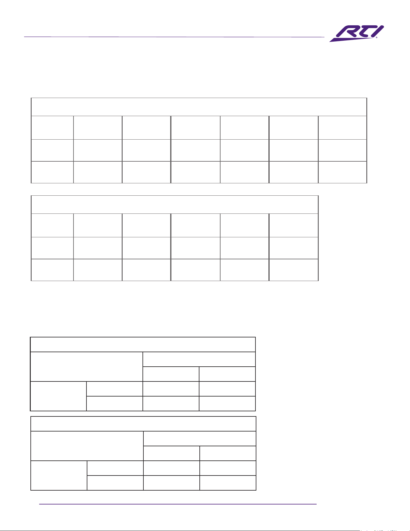
PowerEciencyData
ThefollowingtabledescribestheeciencyandpowerperformanceoftheAMP-4-125andAMP-8-125amplifiers.
The table also includes the derived thermal losses.
Propogation Delay Data
Thefollowingtablesdescribestheinput/outputlatencyperformanceofAMP-4-125andAMP-8-125ampliers.
*AspercompliancetoErP
Specications
AMP-4-125
OUT
Analog S/PDIF
IN
Analog 1177μS 458μS
S/PDIF 1833μS 1104μS
AMP-8-125
OUT
Analog S/PDIF
IN
Analog 1307μS 600μS
S/PDIF 1955μS 1250μS