BLACK (-) - Ground - wired directly to the battery, ground busbar, or other accept-
able ground location.
GREY (+) - Main Power (Running Lights) - Not constant battery power, must be
powered by an ACC (ignition power) triggered source. See the section "ACC Power
Source from Popular Make and Models" for a vehicle-specic list of ACC power
locations.
GREEN (+) - Right Turn Signal - Power from right turn signal bulb or wiring (if
equipped).
YELLOW (+) - Left Turn Signal - Power from left turn signal bulb or wiring (if
equipped).
GREEN/YELLOW Combined (+) - Supporting Brake Light Signal - Power from
brake light bulb, wiring, or switch.
RED (+) - Strobe Light Activation - Power from an on-o dash switch.
BROWN (+) - Amber Light Steady Override - Power through an on-o dash switch.
WHITE (+) - White Light Steady Override - Power through an on-o dash switch.
BLUE (-) - Flash Pattern Selection - Ground through an (on)-o momentary dash
switch (each tap advances to the next ash pattern).
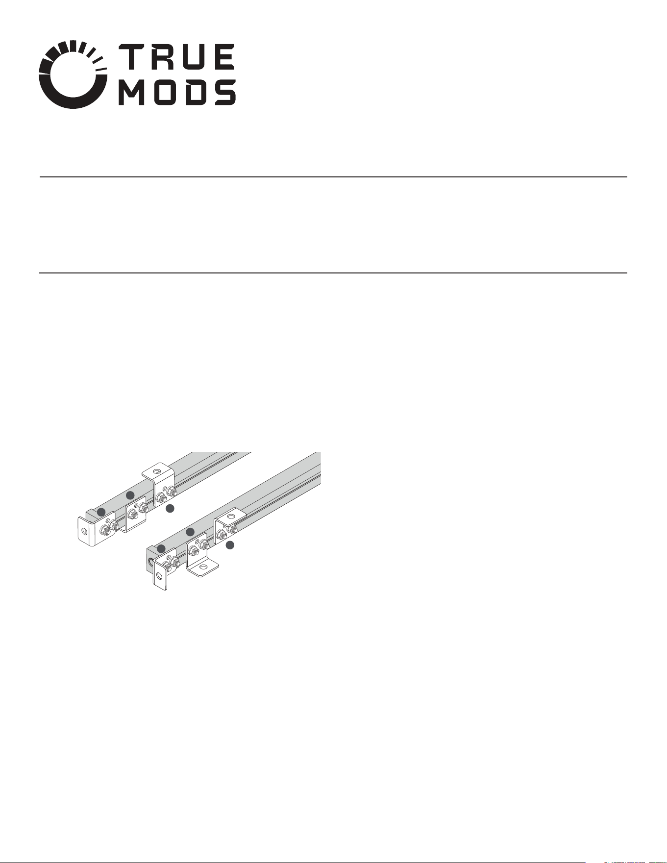
Slide 4 of the fasteners into the mounting rail through the open end.
Place 1 L-bracket over each set of fasteners in the desired mounting position.
Secure the brackets to the light bar with the supplied nuts.
Chose a mounting location.
NOTE: Keep in mind that the mounting location must:
Allow the light to be clearly visible from behind and,
Not damage, or interfere with, any of the vehicle’s safety systems.
Test t the light.
Mark the location of the mounting holes.
NOTE: Always make sure that no vehicle systems or wiring will be damaged when
drilling the mounting holes.
Drill the mounting holes.
Secure the light to the mounting surface.
Assembling the Lightbar Mounting Brackets
NOTE: The light bar comes with 6 fasteners. 4 are for the brackets (2 per bracket)
and 2 are spares. The light bar does not come with the fasteners to mount the bar to
your vehicle.
NOTE: There are 6 possible ways to mount the L-brackets to the light bar. See the
Mounting Diagram for more information.
Mounting Diagram:
Mounting the Light Bar
LED Chase Light Bar with TBT/Strobe/Scanner
•
•
www.truemods.com
US Toll Free: 1-855-533-6654
International: 1-909-212-0993
Fax: (909) 575-6722
E-mail: [email protected]
True Mods © 2012-2021 All Rights Reserved
process. Check both sides of the mounting surface before drilling begins. Also de-burr any holes
and remove any metal shards or remnants. Install grommets into all wire passage holes.
Do not attempt to activate or control this device in a hazardous driving situation.
The installer or user must make sure the intended mounting location and application of the
product conform to the law set forth by the federal, state, or local agency.
IMPORTANT: READ CAREFULLY BEFORE ASSEMBLY AND USE.
•
•
•
Installer of this product must have a good understanding of automotive electronics, systems, and
procedures.
This product contains strobe light(s), halogen light(s), high-intensity LEDs, or a combination of
these components. Do not look directly into the lights. Momentary blindness and/or injury to the
eyes could result.
If mounting this product requires drilling holes, the installer MUST be sure that no vehicle
components or other vital parts could be damaged by the drilling process.
Manual ID: PIM-00000158-V003
Mounting:
1.
2.
3.
1.
2.
3.
4.
5.
2
3
1
5
6
4
Wiring:

True Mods © 2012-2021 All Rights Reserved
The following is a list of common ACC power locations on various UTV models. This
list is only a guide, always verify key-on power and ground with a DMM or test light.
Never use a vehicle’s ACC power circuit to supply voltage directly to the light bar.
Instead, use a relay triggered by an ACC power source to supply the light with fused
power directly from the battery.
Can-Am
Maverick: Many Maverick models have a 3-post distribution block inside the center
console, behind the gear selector, on the passenger side of the console. One post is
ground, one is constant power, and the last is switched ACC power.
Commander: Most Commander models have an unused accessory plug behind the
center dash console.
Defender: Most Defenders have a 3-post distribution block behind the center of the
dash. On models without a heater, the block will be open and accessible and covered
by a plastic cap. On models with a heater, the heater will need to be moved to gain
access to the block. One post is ground, one is constant power, and one is switched
ACC power.
Polaris
Most Polaris UTVs have a 3-post distribution block mounted under the hood on the
rewall. One post is ground, one is constant power, and one is switched ACC power.
Keep in mind that some models do not come from the factory with a constant power
and ground supply at the distribution block, only ACC power.
Honda
Talon: Most Talons come with an unused blue ACC plug under the hood. It will be
strapped to the support bar directly in front of the steering wheel.
Pioneer: Honda recommends borrowing power from the stock fuse box. An accessory
power wire can be spliced into one of the two white/black wires coming o the back
of the 15A ACC fuse.
Yamaha
YXZ/Viking: The easiest place to tap into switched ACC power is at the back of the
accessory (cigarette lighter) plug.
Wolverine: Older models have a single white accessory plug under the plastic hood,
close to the center of the dash cross-member. Newer X2/X4 models have several
white accessory plugs behind the dash, just to the right of the steering column.
Kawasaki
Teryx: The easiest place to tap into switched ACC power is at the back of the
accessory (cigarette lighter) plug.
Mule: ACC power can be found in two places on most Mule models. Under the front
hood, in the center of the rewall is a hole. There will be two wires (black/yellow,
brown/white) inside that hole. The brown/white wire is power and the black/yellow
wire is ground. There will also be two wires (black/yellow, brown/white) in the back,
under the bed, along the passenger side frame rail. Again, the brown/white wire is
power and the black/yellow wire is ground.
Sim. = Simultaneous - AMBER LEDs ash at the same time.
Alt. = Alternate - AMBER LEDs ashes alternately between sides.
Input Voltage: 8-16V DC
Input Current@ 12V DC:
Running Lights - 0.89A
Left Turn Signal - 0.92A
Right Turn Signal - 0.90A
Supporting Brake Lights - 0.80A
Strobe Light - MAX 1.10A
Amber Steady Override - 1.31A
White Steady Override - 1.50A
Specications:
1.
2.
3.
4.
5.
6.
7.
8.
Single Flash 75FPM Sim.
Single Flash 75FPM Sim. + White Scanner
Single Flash 75FPM Alt.
Single Flash 75FPM Alt. + White Scanner
Rapid Flash Sim.
Rapid Flash Sim. + White Scanner
Rapid Flash Alt.
Rapid Flash Alt. + White Scanner
Flash Pattern:ACC Power Source from Popular Make and Models: