Recess Mount and Steering Column Turn Signal Switch with Flasher
www.truemods.com
US Toll Free: 1-855-533-6654
International: 1-909-212-0993
Fax: (909) 575-6722
E-mail: [email protected]
True Mods © 2012-2022 All Rights Reserved
Manual ID: PIM-00000216-V001
Steering Column Turn Signal Switch Mounting Instruction:
Select a desired mounting location of the turn signal switch on the steering
column. Ideally, the LED indicator lights on the switch should be visible from the
driver’s seat.
Attach the clamp to the turn signal switch housing by inserting the steel band into
the groove on the turn signal switch housing.
Disassemble the clamp by turning the fastener counter-clockwise.
Wrap the steel band around the desired mounting location on the steering column.
Reassemble the clamp by inserting the steel band into the fastener assembly and
turn fastener clockwise. Adjust position of the turn signal switch on the steering
column prior to tightening the fastener completely.
Test the operation of the steering wheel with the turn signal switch attached to
the steering column to make sure the switch doesn’t impede the driver’s ability in
properly operating the vehicle. Select a dierent mounting location of the turn
signal switch if necessary.
Insert the terminals into the wiring connector based on the Steering Column Turn
Signal Switch Diagram.
1.
2.
3.
4.
5.
6.
7.
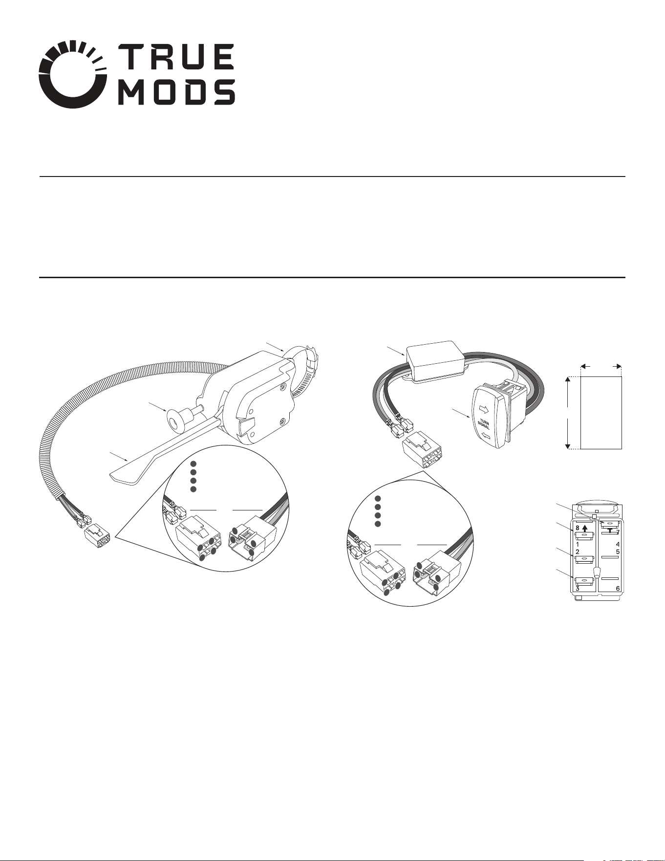
Steering Column Turn Signal Switch Diagram:
Steering Column Turn Signal Switch with Built-In Flasher
Steering Column Turn Signal Switch Mounting Instruction:
Select a desired mounting location for the turn signal switch. Refer to Turn Signal
Switch Diagram for the size of the cutout hole needed.
NOTE: Always make sure that no vehicle systems or wiring will be damaged when
making the cutout hole.
Proceed on making the cutout hole on the desired mounting location.
Perform the necessary wiring connection. Refer to the Turn Signal Switch
Diagram.
Feed the turn signal asher box through the cutout hole for the switch.
Secure the turn signal asher box to a surface using the included 3M double sided
tape.
Insert the switch into the cutout.
1.
2.
3.
4.
5.
6.
Turn Signal Switch with Flasher Diagram:
Turn Signal Switch with Flasher
4-way Flasher
Switch
Steering Column Clamp
Left/Right Turn
Signal Lever
1
2
4
3
2
1
3
4
SWITCH SIDE HARNESS SIDE
1
2
3
4
YELLOW - Left Turn Signal
RED - 12V+
GREEN - Right Turn Signal
WHITE - Ground
Turn Signal
Switch
Turn Signal
Flasher Box
Cutout Size
for Switch
13/16”
1-7/16”
1
2
4
3
2
1
3
4
SWITCH SIDE HARNESS SIDE
1
2
3
4
YELLOW - Left Turn Signal
RED - 12V+
GREEN - Right Turn Signal
WHITE - Ground
YELLOW - Left
Turn Signal
RED - 12V +
GREEN - Right
Turn Signal
WHITE - Ground
•
•
Do not install this product or route any wires in the deployment area of your air bag. Equipment
mounted or located in the air bag deployment area will damage or reduce the eectiveness of the
air bag, or become a projectile that could cause serious personal injury or death. Refer to your
vehicle owner’s manual for the air bag deployment area. The User/Installer assumes full
responsibility to determine proper mounting location, based on providing ultimate safety to all
passengers inside the vehicle.
Do not attempt to activate or control this device in a hazardous driving situation.
IMPORTANT: READ CAREFULLY BEFORE ASSEMBLY AND USE.
•
•
•
Proper installation of this product requires the installer to have a good understanding of automotive
electronics, systems, and procedures.
If mounting this product requires drilling holes, the installer MUST be sure that no vehicle
components or other vital parts could be damaged by the drilling process. Check both sides of the
mounting surface before drilling begins. Also de-burr any holes and remove any metal shards or
remnants. Install grommets into all wire passage holes.
If this manual states that this product may be mounted with suction cups, magnets, tape or Velcro®,
clean the mounting surface and dry thoroughly prior to apply adhesive for maximum adhesion.
UTV Turn Signal Kit Wiring Harness
•
•
www.truemods.com
US Toll Free: 1-855-533-6654
International: 1-909-212-0993
Fax: (909) 575-6722
E-mail: [email protected]
True Mods © 2012-2022 All Rights Reserved
Do not install this product or route any wires in the deployment area of your air bag. Equipment
mounted or located in the air bag deployment area will damage or reduce the eectiveness of the
air bag, or become a projectile that could cause serious personal injury or death. Refer to your
vehicle owner’s manual for the air bag deployment area. The User/Installer assumes full
responsibility to determine proper mounting location, based on providing ultimate safety to all
passengers inside the vehicle.
Do not attempt to activate or control this device in a hazardous driving situation.
IMPORTANT: READ CAREFULLY BEFORE ASSEMBLY AND USE.
•
•
•
Proper installation of this product requires the installer to have a good understanding of automotive
electronics, systems, and procedures.
If mounting this product requires drilling holes, the installer MUST be sure that no vehicle
components or other vital parts could be damaged by the drilling process. Check both sides of the
mounting surface before drilling begins. Also de-burr any holes and remove any metal shards or
remnants. Install grommets into all wire passage holes.
If this manual states that this product may be mounted with suction cups, magnets, tape or Velcro®,
clean the mounting surface and dry thoroughly prior to apply adhesive for maximum adhesion.
Manual ID: PIM-00000217-V001
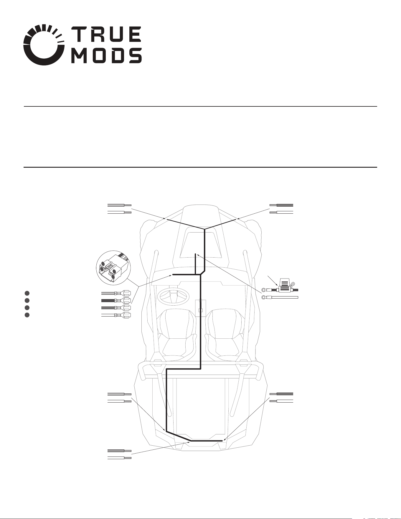
Wiring Harness Diagram:
Left Rear Turn Signal
YELLOW - Rear Left Turn (+)
WHITE - Rear Ground (-)
Left Front Turn Signal
YELLOW - Front Left Turn (+)
WHITE - Front Ground (-)
License/Running Lights
ORANGE - License Running (+)
WHITE - Rear Ground (-)
Right Front Turn Signal
GREEN - Front Right Turn (+)
WHITE - Front Ground (-)
Main Power/Ground Input
RED - Main Power Input (ACC)
WHITE - Main Ground Input
In-line Fuse Holder
Right Rear Turn Signal
GREEN - Rear Right Turn (+)
WHITE - Rear Ground (-)
Turn Signal Switch
YELLOW - Left Turn Signal
RED - 12V
+
GREEN - Right Turn Signal
WHITE - Ground
1
2
3
4
4
3
2
1

Wiring Harness Installation Instruction:
Before Installation:
Routing the Wiring Harness:
NOTE: The following instructions are just suggestions to be used as reference. The
process of routing wires through a vehicle will vary between models and personal
preference.
Determine how power and ground is to be supplied to the wiring harness.
NOTE: The RED main power input wire on the wiring harness must be connected
to an ACC (ignition power) triggered source. See the section “ACC Power Source
from Popular Make and Models” for a vehicle-specic list of ACC power locations.
Locate the positions of the front and rear turn signal lights on the automobile.
NOTE: If new turn signal lights are to be installed on the automobile, be sure to
install them as far out to the corners as possible.
Determine how the wiring harness to each of the turn signal lights and license
plate/running lights (if using) are to be routed throughout the vehicle. Including
the structure in which the wiring harness will be secured to via the included zip
ties. Consider routing the wiring harness alongside existing hoses and wires and
ensuring it does not come in contact with any moving engine or suspension parts.
NOTE: Although ample of wiring is included with the harness, additional wires may
be needed depending on the automobile and how the wires are to be routed.
Determine how the wiring connections between the wiring harness and the turn
signal/license plate lights are to be connected. Both female and male bullet
connectors are included for this purpose. Refer to the Bullet Connectors Diagram.
1.
2.
3.
4.
Remove the fuse from the in-line fuse holder.
Start by removing/loosening the front and rear (if present) center consoles from
the automobile.
NOTE: It is not a must to remove all panels completely as the wiring harness can
be tucked underneath the panels with just an opening.
If working with an automobile that has the factory ACC power source located
behind the dash/under the hood, feed the leads for the Main Power and Ground
Inputs from the cockpit/center console through the dash into under the hood.
Make the connections of the Main Power and Ground Inputs to the ACC power
and ground source as desired. Refer to the “ACC Power Source from Popular
Make and Models” section.
Run the Leads to Turn Signal Switch from the center console to the cockpit where
the turns signal switch is located and insert the terminals into the wiring connector
if it is to be used. Refer to Wiring Harness Diagram.
Complete the connection between the wiring harness and the turn signal switch.
Feed the Leads to Front Turn Signal Lights from the cockpit/center console
through the dash into under the hood.
Route the wiring leads to the left and right front turn signal lights.
Complete the wiring connections to the front turn signal lights by securing the
wiring harness with zip ties and extending or shortening the wires if necessary.
Feed the Leads to Rear Turn Signal Lights from the cockpit/center console,
through the rear center console (if present), and through the rewall.
Route the wiring leads to the left and right rear turn signal lights and license
plate/running lights (if using).
1.
2.
3.
4.
5.
6.
7.
8.
9.
10.
11.
The following is a list of common ACC power locations on various UTV models. This
list is only a guide, always verify key-on power and ground with a DMM or test light.
Never use a vehicle’s ACC power circuit to supply voltage directly to the whip.
Instead, use a relay triggered by an ACC power source to supply the light with fused
power directly from the battery.
Can-Am
Maverick: Many Maverick models have a 3-post distribution block inside the center
console, behind the gear selector, on the passenger side of the console. One post is
ground, one is constant power, and the last is switched ACC power.
Commander: Most Commander models have an unused accessory plug behind the
center dash console.
Defender: Most Defenders have a 3-post distribution block behind the center of the
dash. On models without a heater, the block will be open and accessible and covered
by a plastic cap. On models with a heater, the heater will need to be moved to gain
access to the block. One post is ground, one is constant power, and one is switched
ACC power.
Polaris
Most Polaris UTVs have a 3-post distribution block mounted under the hood on the
rewall. One post is ground, one is constant power, and one is switched ACC power.
Keep in mind that some models do not come from the factory with a constant power
and ground supply at the distribution block, only ACC power.
Honda
Talon: Most Talons come with an unused blue ACC plug under the hood. It will be
strapped to the support bar directly in front of the steering wheel.
Pioneer: Honda recommends borrowing power from the stock fuse box. An accessory
power wire can be spliced into one of the two white/black wires coming o the back
of the 15A ACC fuse.
Yamaha
YXZ/Viking: The easiest place to tap into switched ACC power is at the back of the
accessory (cigarette lighter) plug.
Wolverine: Older models have a single white accessory plug under the plastic hood,
close to the center of the dash cross-member. Newer X2/X4 models have several
white accessory plugs behind the dash, just to the right of the steering column.
Kawasaki
Teryx: The easiest place to tap into switched ACC power is at the back of the
accessory (cigarette lighter) plug.
Mule: ACC power can be found in two places on most Mule models. Under the front
hood, in the center of the rewall is a hole. There will be two wires (black/yellow,
brown/white) inside that hole. The brown/white wire is power and the black/yellow
wire is ground. There will also be two wires (black/yellow, brown/white) in the back,
under the bed, along the passenger side frame rail. Again, the brown/white wire is
power and the black/yellow wire is ground.
ACC Power Source from Popular Make and Models:
True Mods © 2012-2022 All Rights Reserved
Bullet Connectors Diagram:
Crimp
Connectors
Crimp
Connectors
To Wiring
Harness
To Turn
Signal Lights
Complete the wiring connections to the rear turn signal lights and license plate
light (if using) by securing the wiring harness with zip ties and extending or
shortening the wires if necessary.
Make sure all wiring and wire loom are securely axed to the vehicle.
Re-insert the fuse into the in-line fuse holder.
Test out the turn signal and license plate light functions.
Re-install any covers and panels that were removed in the prior steps.
12.
13.
14.
15.
16.