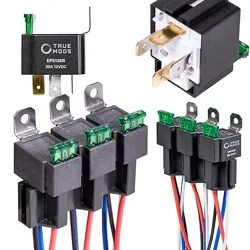
Negative Switched Headlights Conversion Wiring Harness for H4 Lights
www.truemods.com
US Toll Free: 1-855-533-6654
International: 1-909-212-0993
Fax: (909) 575-6722
E-mail: [email protected]
True Mods © 2012-2021 All Rights Reserved
Manual ID: PIM-00000102-V002
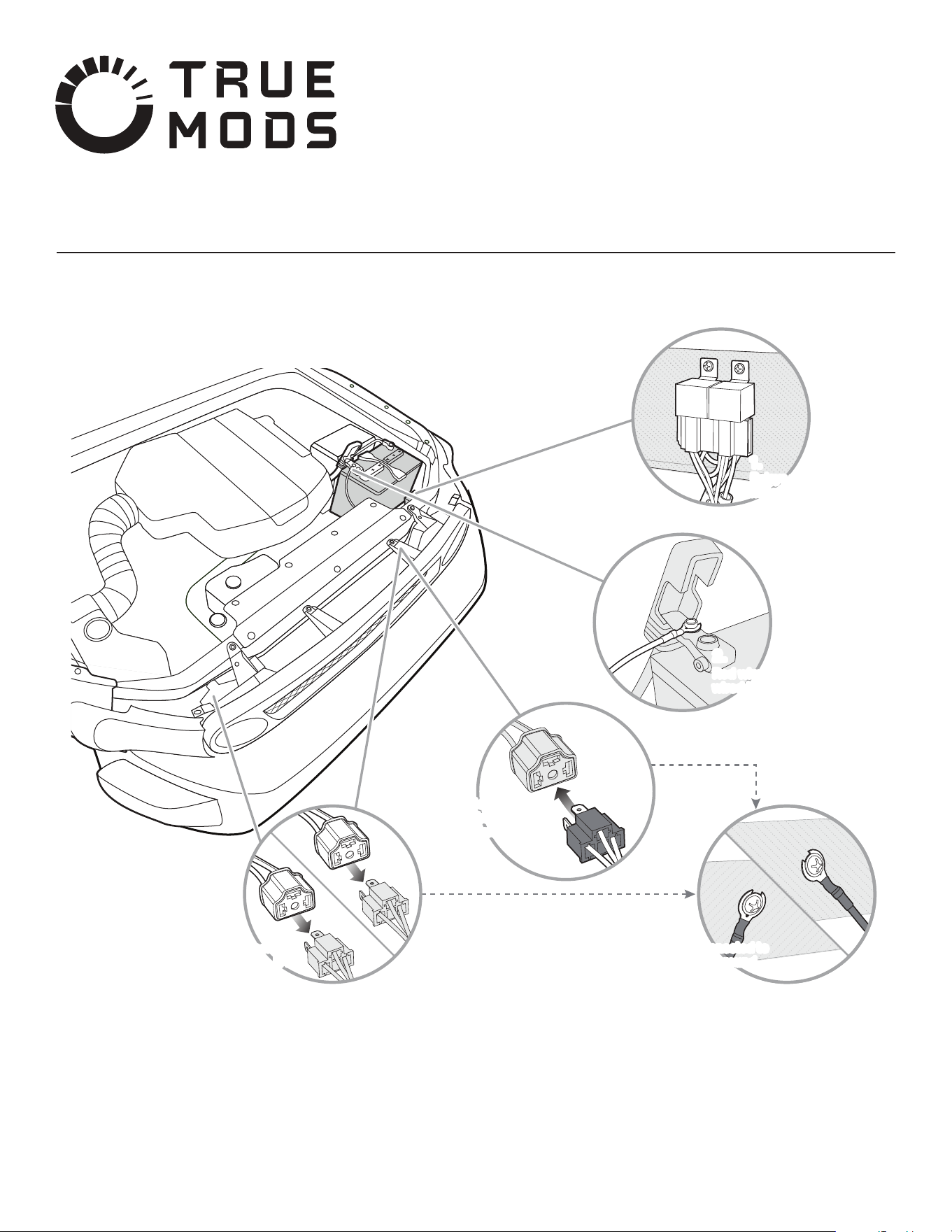
Installation Diagram:
Relays secured to a solid
mounting surface.
1.
2.
3.
4. 5.
Red wire and 30A fuse
wired to battery power.
Black male connector
plugged into vehicle
lighting harness.
Yellow female sockets
plugged into the H4
headlights.
Black wires connected to
a clean chassis ground.
Relays secured to a solid
mounting surface.
1.
2.
3.
4.
L
R
5.
Red wire and 30A fuse
wired to battery power.
Black male connector
plugged into vehicle
lighting harness.
Yellow female sockets
plugged into the H4
headlights.
Black wires connected to
a clean chassis ground.

True Mods © 2012-2021 All Rights Reserved
Installation Instruction:
Unplug the headlight harness from the back of the light.
Turn the ignition on.
Turn the headlights o.
Test the three terminals of the headlight harness for power.
A negative switched vehicle will have one 12v power wire.
A positive switched vehicle will have no wires reading voltage.
-
-
-
-
-
-
The relays will need to be mounted within 11” of the positive battery terminal.
The relays should be mounted to a solid surface to prevent damage and avoid premature failure of the relays.
It is a good idea to lay the harness out over the potential install area to verify mounting locations and length of the harness wires.
It would also be a good idea to temporarily install and test the harness before permanently mounting any component.
-
-
-
-
1. Begin by verifying that your vehicle employs a negative switched headlight circuit.
Testing for a Negative Switched Circuit
NOTE:
2.
3.
Install your new headlights according to the included instructions but do not plug the OEM headlight harness into the new headlights.
Find a suitable location to mount the conversion kit relays.
Always verify that no wires are hanging or in danger of being damaged.
One OEM headlight plug will not be used, be sure to secure this socket as well.
Avoid sharp edges, pinch points, and moving parts like fans and belts.
-
-
-
NOTE:
9.
10.
Turn on the headlights and check for proper function.
If you have not done so already, nalize the install by permanently mounting the relays with fasteners and securing any loose wiring harness to a non-moving part of the
vehicle with zip ties. Fasteners and zip ties are user supplied.
The best place to attach these wires is to a preexisting ground bolt or stud.
If this is not possible, the black wires may be attached to a clean, unpainted part of the body by means of a preexisting bolt, self-tapping screws, or sheet metal
screws.
-
-
NOTE:
Make sure the potential grounding location is clean and unpainted.
To get a good connection some paint may need to be removed.
Using a multimeter set to ohms Ω, touch one probe the potential ground location and the other probe to vehicles negative battery post.
If the meter displays less than 0.5 ohms of resistance to the negative battery terminal, the location may be used as a ground point.
-
-
-
-
4. Attach the red fused wire directly to battery power.
Tip: The easiest place to do this would be at the positive battery post. In most cases the fork terminal can be installed on the battery terminal clamping nut.
5.
6.
7.
8.
Connect the black male plug to the OEM headlight socket closest to your chosen relay mounting location. (For example: If you are going to mount the relays to the driver
side of the vehicle then connect the black plug to the driver side OEM headlight socket.)
Find the yellow socket with the shortest wire leads and connect it to the new LED headlight closest to the relay mounting location.
Connect the second yellow socket to the second LED headlight.
Connect the two fork terminals on the black wires to a clean chassis ground.
Verifying A Good Ground Connection: