-
-
-
-
-
-
-
-
-
Waterproof Relay Box for Six 6-pin Relay and Fuses
•
www.truemods.com
US Toll Free: 1-855-533-6654
International: 1-909-212-0993
Fax: (909) 575-6722
E-mail: [email protected]
True Mods © 2012-2023 All Rights Reserved
IMPORTANT: READ CAREFULLY BEFORE ASSEMBLY AND USE.
•
•
Installer of this product must have a good understanding of automotive electronics, systems, and
procedures.
In the case that holes must be drilled in order to properly mount the product, the installer must
examine both sides of the mounting surface before drilling begins. It is the installer’s
responsibility to be sure that no vehicle components or vital parts could be damaged by the
drilling process. De-burr any holes in order to remove metal shards and remnants. Use grommets
in all wire passage holes.
Deployment area of the vehicle air bags must be cleared. Do not install this product or route any
electrical wires near the air bags deployment areas. Refer to your vehicle owner’s manual for the
air bag deployment area. Products or wires mounted in the air bag deployment area will damage,
reduce the eectiveness of the air bag, or even act as a projectile which may cause serious injury
or death. The user/installer of this product assumes full responsibility in determining the proper
mounting location while prioritizing the safety of all passengers in the vehicle.
Manual ID: PIM-00000107-V003
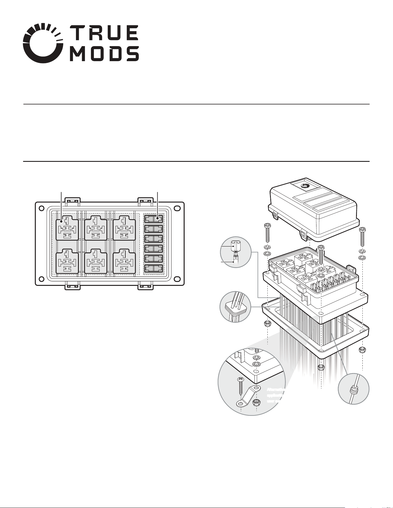
Slots for Bosch Style Relays
Slots for ATC/ATO Fuses
Rubber Gasket
Z-shaped Mounting Bracket
Product Diagram:
Designed for 5-pin or 4-pin Bosch style relays.
Use the included push-on terminals for 14 AWG wires (35 units included, 5 extra).
Use the included cable sealing pad for each of the relay (7 units included, 1 extra).
NOTE: The hole in the middle (for terminal 87A, NC circuit on a 5-pin relay) would be sealed.
Brake the seal only if terminal 87A on 5-pin relays will be utilized.
Designed for ATC/ATO blade fuses.
Use the included push-on blade fuse terminals for 14 AWB wires (14 units included, 2 extra).
Use two of the included cable seals for each of the fuse (14 units included, 2 extra).
Utilized to waterproof the cutout hole when surface mounting the relay box over a cutout hole for
the cable/wiring.
Props the relay box up from the mounting surface to allow clearance of the wiring/cable when
surface mounting the relay box.
Slots for
Bosch Style Relays
Slots for
ATC/ATO Fuses
Installation Diagram:
Terminal
Crimp terminals
onto wires
Crimp terminals
onto wires
Crimp terminals
onto wires
Crimp terminals
onto wires
Insert wires through
cable sealing pad.
Insert wires through
cable sealing pad.
Insert wire through
cable seal.
Insert wire through
cable seal.
Wire
Alternative bracket mount
application. Screw shown is
user supplied.
Alternative bracket mount
application. Screw shown is
user supplied.
Wiring: (applicable models only)
BLACK – Pin 85 – Connect to Ground, can be switched. Energizes relay with pin 86 connected
to power.
WHITE – Pin 86 – Connect to Power, can be switched. Energizes relay with pin 85 connected to
ground. Must be fused @ min. 1A.
YELLOW – Pin 87a – Normally Closed (NC). Connects to common when relay is NOT energized.
BLUE – Pin 87 – Normally Open (NO). Connects to common when the relay IS energized.
RED – Pin 30 – Common. Can be connected to Ground or Power depending on application.
-
-
-
-
-