ITEM #5995673
MODEL #DT-827Kit
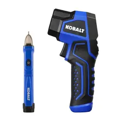
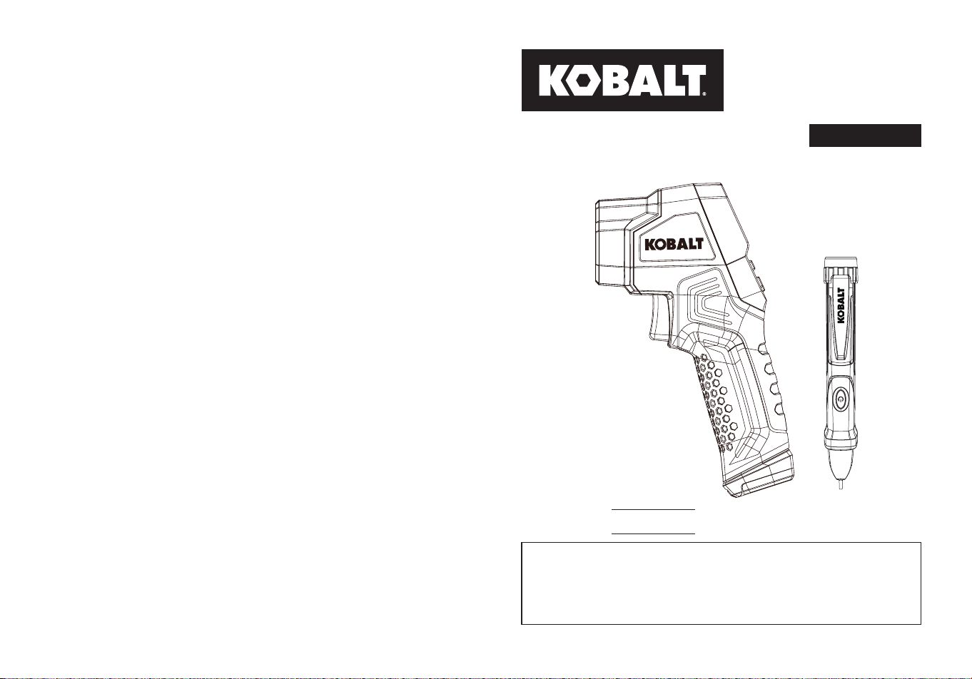
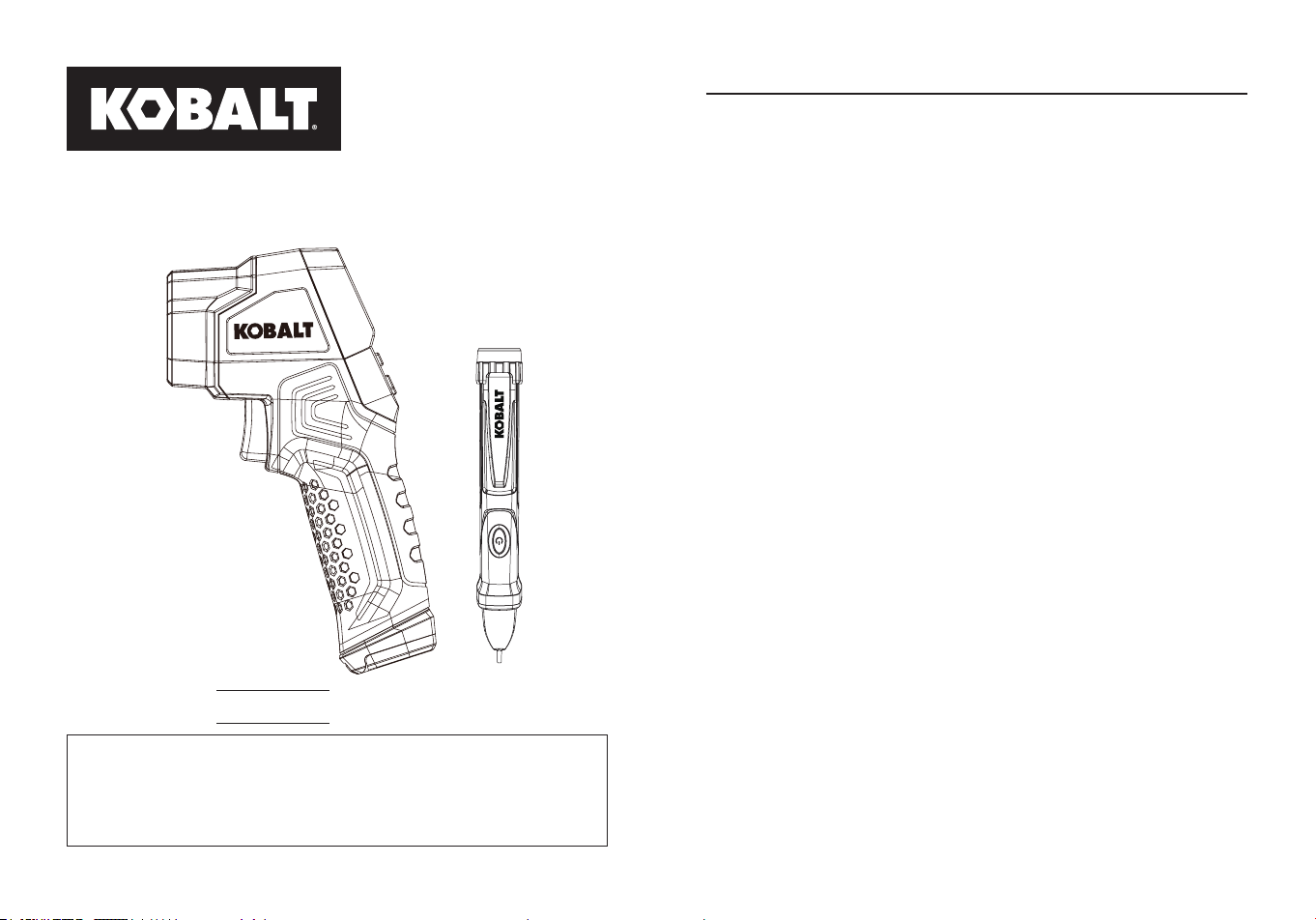
INFRARED THERMOMETER
WITH NCV TESTER
Español p.22
Serial Number
Purchase Date
SG24723
KOBALT and logo design are
trademarks or registered trademarks
of LF, LLC. All rights reserved.
ATTACH YOUR RECEIPT HERE
Thank you for purchasing this KOBALT product.
Questions problems or missing parts?
Before returning. contact us on:
888-356-2258
, 8 a.m. - 8 p.m., EST, Monday - Sunday.
or
2 3
TABLE OF CONTENTS
Product Specications ......................................................................3
Package Contents ............................................................................4
Safety Information ............................................................................7
Operating Instructions ......................................................................8
Care and Maintenance ....................................................................13
Troubleshooting ...............................................................................13
Warranty ..........................................................................................21
NCV Tester
Product Specications .....................................................................14
Package Contents ...........................................................................15
Safety Information ...........................................................................17
Operating Instructions .....................................................................19
Care and Maintenance ....................................................................21
Troubleshooting ...............................................................................21
Warranty ..........................................................................................21
Non-Contact Infrared Thermometer
Non-Contact Infrared Thermometer
PRODUCT SPECIFICATIONS
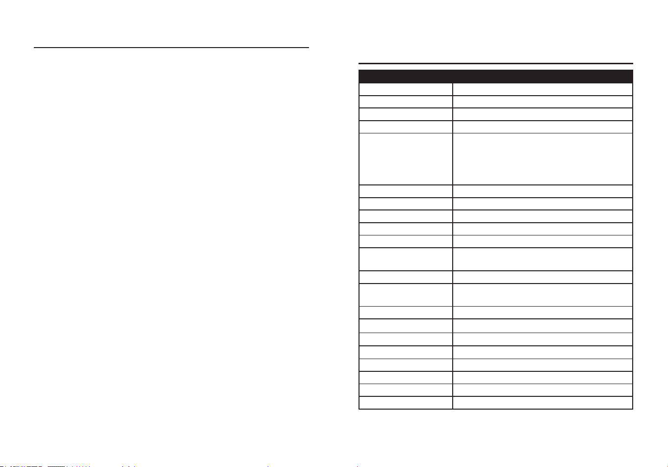
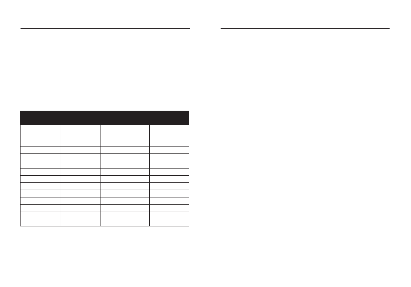
GENERAL SPECIFICATIONS
Measurement Range -58 to 1022°F (-50 to 550°C)
Units Settable to °F or °C
Distance to Spot Ratio 12:1
Display Resolution 0.1°F/°C
Accuracy
Assumes ambient operating temperature of
73 to 77°F (23 to 25°C)
±6.3°F (3.5°C) at -58 to 68°F (-50 to 20°C)
±2.0% or 3.6°F (±2.0°C) at 68 to 1022°F (20
to 550°C)
Response Time <300 ms
Spectral Response 8~14 μm
Emissivity Digitally adjustable from 0.10 to 1.0
Display Negative display
Over Range Indication LCD will show “----”
Polarity
Automatic (no indication for positive polarity);
Minus (-) sign for negative polarity
Targeting Laser Single laser sighting
Diode Laser
Output <1mW, Wavelength 630~670 nm,
Class 2 laser product
Battery 1 x 9 V battery
Operating Temperture 32°F to 122°F(0°C to 50°C)
Storage Temperture -4°F to 122 °F(-20°C to 50°C)
Relative Humidity 10%~90%RH operating, <80%RH storage
Operating Altitude 7000 ft (2000 m) maximum
Net Weight Approx.0.36 lbs. (164 g)
Dimensions 3.62 x 1.77 x 6.81 in. (92 x 45 x 173 mm)
Safety IEC EN 60825-1, EN 50689
Note:
This equipment conform to EN 50689(Safety of laserproducts-
Particular Re for Consumer Laser Products.
4 5
PART DESCRIPTION QUANTITY
A Infrared thermometer DT-826B 1
B NCV Tester AC-6H 1
C Carrying case 1
D 9-volt battery (Infrared thermometer) 1
E 1.5-volt battery (NCV Tester) 2
A
B E
C D
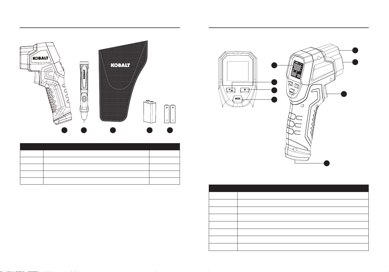
PACKAGE CONTENTS
PACKAGE CONTENTS
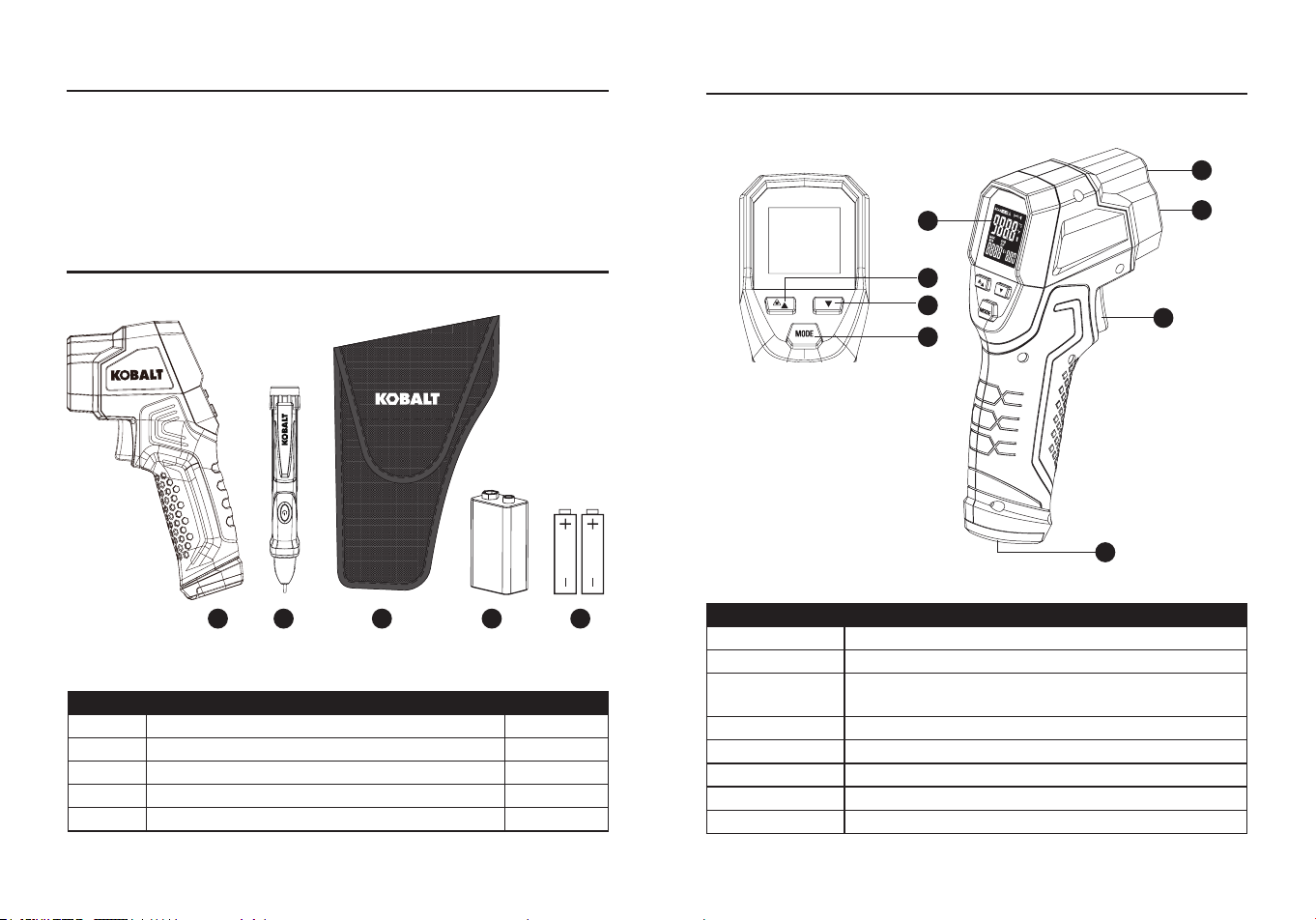
PART DESCRIPTION
A LCD Display
B Up Button (for Emissivity, High Alarm, Low Alarm)
C
Down Button (for Emissivity, High Alarm, Low
Alarm)
D MODE Button (for cycling through the mode loop)
E Laser Hole
F IR Sensor
G Measurement Trigger
H Battery Cover
B
C
D
A
E
F
G
H
Note:
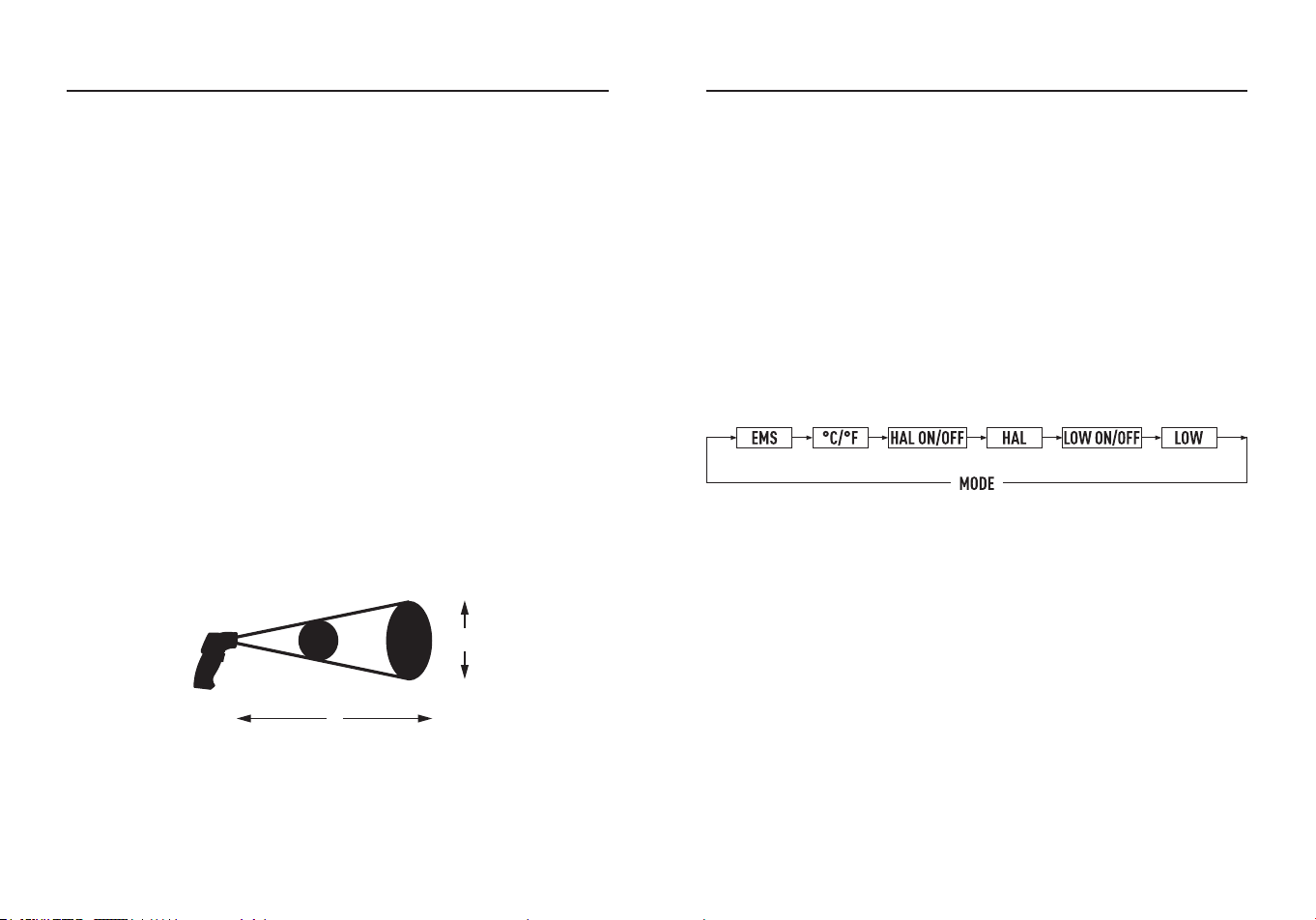
Field of View: Make sure that the target is larger than the unit’s
spot size. The smaller the target, the closer you should be to it. When
accuracy is critical, make sure the target is at least twice as large as
the spot size.
PRODUCT SPECIFICATIONS
6 7
PACKAGE CONTENTS
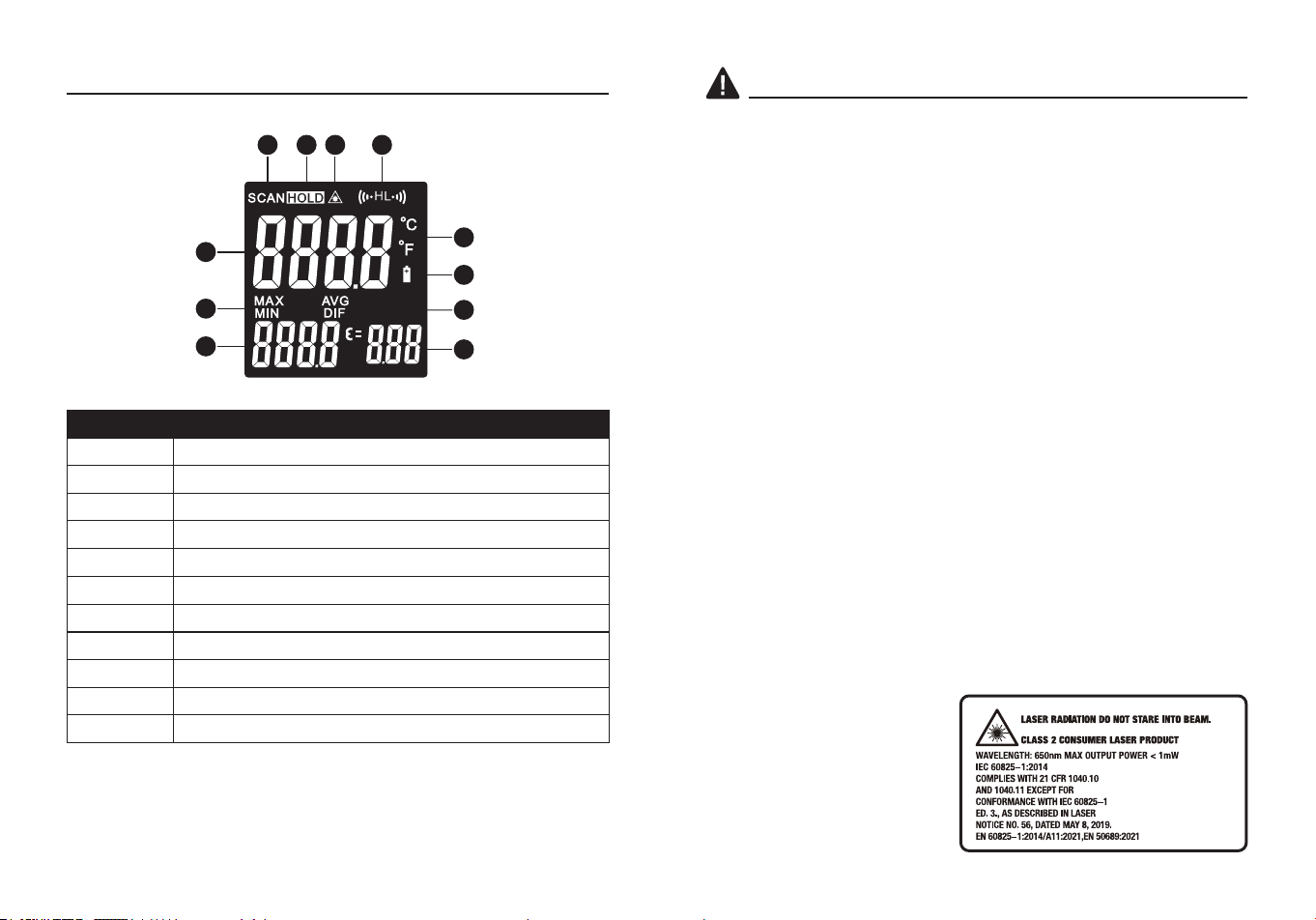
PART DESCRIPTION
A Scan
B Data Hold
C Laser “ON”
D High Alarm and Low Alarm
E °C/°F
F Low Power
G Emissivity
H Emissivity Value
I Temperature values for the MAX/MIN/DIF/AVG
J Symbols for MAX/MIN/DIF/AVG
K Current Temperature Value
A
B
C
D
E
F
G
H
I
J
K
SAFETY INFORMATION
WARNINGS
●Do not use for medical purposes.
●Keep out of reach of children.
●Do not open the housing other than battery compartment.
●Avoid direct eye exposure.
●Do not expose the tool to explosive gas or vapor or to rain or wet
conditions.
●Stay alert, watch what you are doing and use common sense when
operating the tool. Do not use while you are tired or under the
inuence of drugs, alcohol or medication. A moment of inattention
may result in serious personal injury.
●Use the tool in accordance with these instructions, taking into account
the working conditions and the work to be performed. Use of the
tool for operations dierent from those intendeds could resulin a
hazardous situation.
●Have your tool serviced by a qualied repair person using only
identical replacement parts. This will ensure that the safety of the tool
is maintained.
●Do not use the tool if it operates incorrectly or abnormally or if it is
damaged.
●BEFORE EACH USE, inspect the general condition of the tool. Check
for:
-loose hardware.
-misalianment or binding of parts.
-cracked or broken parts,
-damaged electrical wiring,
-any other condition that may aect its safe operation.
●Use extreme caution when the laser beam is turned on.
●Do not let the beam enter your
eye, another person’s eye or
the eye of an animal.
●Be careful no to let the beam
on a reective surface strike
your eye.
●Do not allow the laser light
beam impinge on any gas
which can explode.
RAYONNEMENT LASER NE REGARDEZ PAS LE FAISCEAU.
8 9
OPERATING INSTRUCTIONS
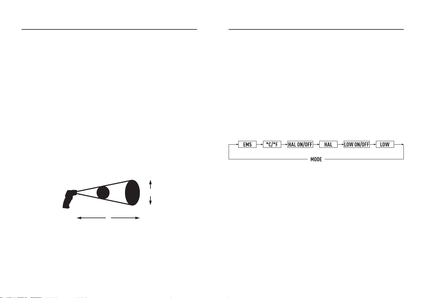
Distance & Spot Size
●As the distance (D) from the object increases, the spot size (S) of the
area measured by the unit becomes larger.
●The relationship between distance and spot size for each unit is listed
below.
●The spot sizes indicate 90% encircled energy.
How it Works
●Infrared thermometers measure the surface temperature of an object.
●The unit’s optics sense emitted, reected, and transmitted energy,
which is collected and focused onto a detector.
●The unit’s electronics translate the information into a temperature
reading, which is display on the unit.
●The laser is used for aiming purposes only.
Field of View
●Make sure that the target is larger than the unit’s spot size, the
smaller the target, the closer you should be to it.
●When accuracy is critical, make sure the target is at least twice as
large as the spot size.
Locating a hot Spot
●To nd a hot spot aim the thermometer outside the area of interest,
then scan across with an up and down motion until you locate hot
spot.
D
S
Distance : Spot = 12:1
0.5@6 in.
1.0@12 in.
12.5@152 mm
25@305 mm
OPERATING INSTRUCTIONS
Button Function
●Up Button to turn on or o the laser.
●Short press MODE Button to change MAX/MIN/DIF/AVG.
●To set values for the High Alarm (HAL), Low Alarm (LAL) and
Emissivity (EMS), press and hold the MODE Button until the
appropriate code appears in the display, press the Up and Down
Buttons to adjust the desired values.
°C/°F
●Press Up/Down Button to change the temperature unit (°C or °F).
HAL (LOW) On/O
●Press the Up or Down Button to turn on or o.
●Press the Measurement Trigger to conrm the High (Low) alarm
mode.
HAL (LOW) Adjustment
●The High (Low) alarm adjustable form -50 to 550°C (-58 to 1022°F).
MAX/MIN/DIF/AVG Display
●MAX/MIN/DIF/AVG indicate the MAX/MIN/DIF/AVG record that
displays between the pressing and releasing the “ON/OFF” Button
each time.
MAX=Maximum, Maximum value measured.
MIN=Minimum, Minimum value measured.
MODE Button
●Press the MODE Button also allows you to access the set state,
Emissivity (EMS), °C/°F, HAL On/O, HAL adjustment LOW On/O,
LOW adjustment.
●Each time you press set you advance through the mode cycle.
●The diagram shows the sequence of functions in the mode cycle.
10 11
OPERATING INSTRUCTIONS
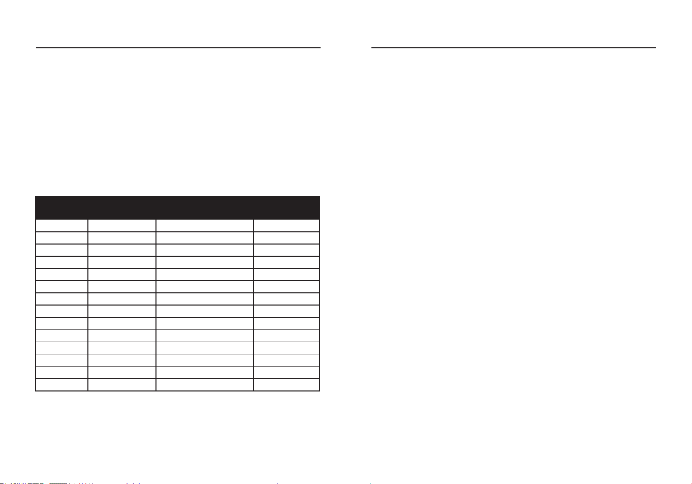
Substance
Thermal
Emissivity
Substance
Thermal
Emissivity
Asphalt 0.90 to 0.98 Cloth (black) 0.98
Concrete 0.94 Human skin 0.98
Cement 0.96 Lather 0.75 to 0.80
Sand 0.90 Charcoal (powder) 0.96
Earth 0.92 to 0.96 Lacquer 0.80 to 0.95
Water 0.92 to 0.96 Lacquer (matt) 0.97
Ice 0.96 to 0.98 Rubber (black) 0.94
Snow 0.83 Plastic 0.85 to 0.95
Glass 0.90 to 0.95 Timber 0.90
Ceramic 0.90 to 0.94 Paper 0.70 to 0.94
Marble 0.94 Chromium oxides 0.81
Plaster 0.80 to 0.90 Copper oxides 0.78
Mortar 0.89 to 0.91 Iron oxides 0.78 to 0.82
Brick 0.93 to 0.96 Textiles 0.90
●To compensate, cover the surface to be measured with masking
tape or at black paint, allow time for the tape to reach the same
temperature as the material underneath it, measure the temperature
of the tape or painted surface.
Emissivity
●Emissivity is a term used to describe the energy-emitting
characteristics of materials.
●Most (90% of typical applications) organic materials and painted or
oxidized surfaces have an emissivity of 0.95 (pre-set in the unit).
●Inaccurate readings will result from measuring shiny or polished metal
surfaces.
DIF=Dierence, Dierence value between maximum and minimum
values measured.
AVG=Average, Average value measured.
Measurement Operation
●Point it toward the surface to be measured. Pull and hold the Trigger
to turn the meter on and begin testing.
The display will light if the battery is good, replace the battery if the
display does not light.
●Release the Trigger and the HOLD display icon will appear on the
LCD indicating that the reading is being held.
In HOLD status, press the Up Button to turn on or o the laser, and
press the Down Button to turn on or o the backlight.
●The meter will automatically power down after approximately 10
seconds after the trigger is released (Unless the unit is locked on).
Measurement Notes
●Point the IR Sensor directly at the target object. The meter automati
cally compensa tes for temperat ure deviatio ns from ambient
temperature.
●Keep in mind that it will take up to 30 minutes to adjust to wide
ambient temperatures. Some time (several minutes) is required after
the low (and before the high) temperature measurements are made.
●This is a result of the cooling process, which must take place for the
IR sensor.
OPERATING INSTRUCTIONS
12 13
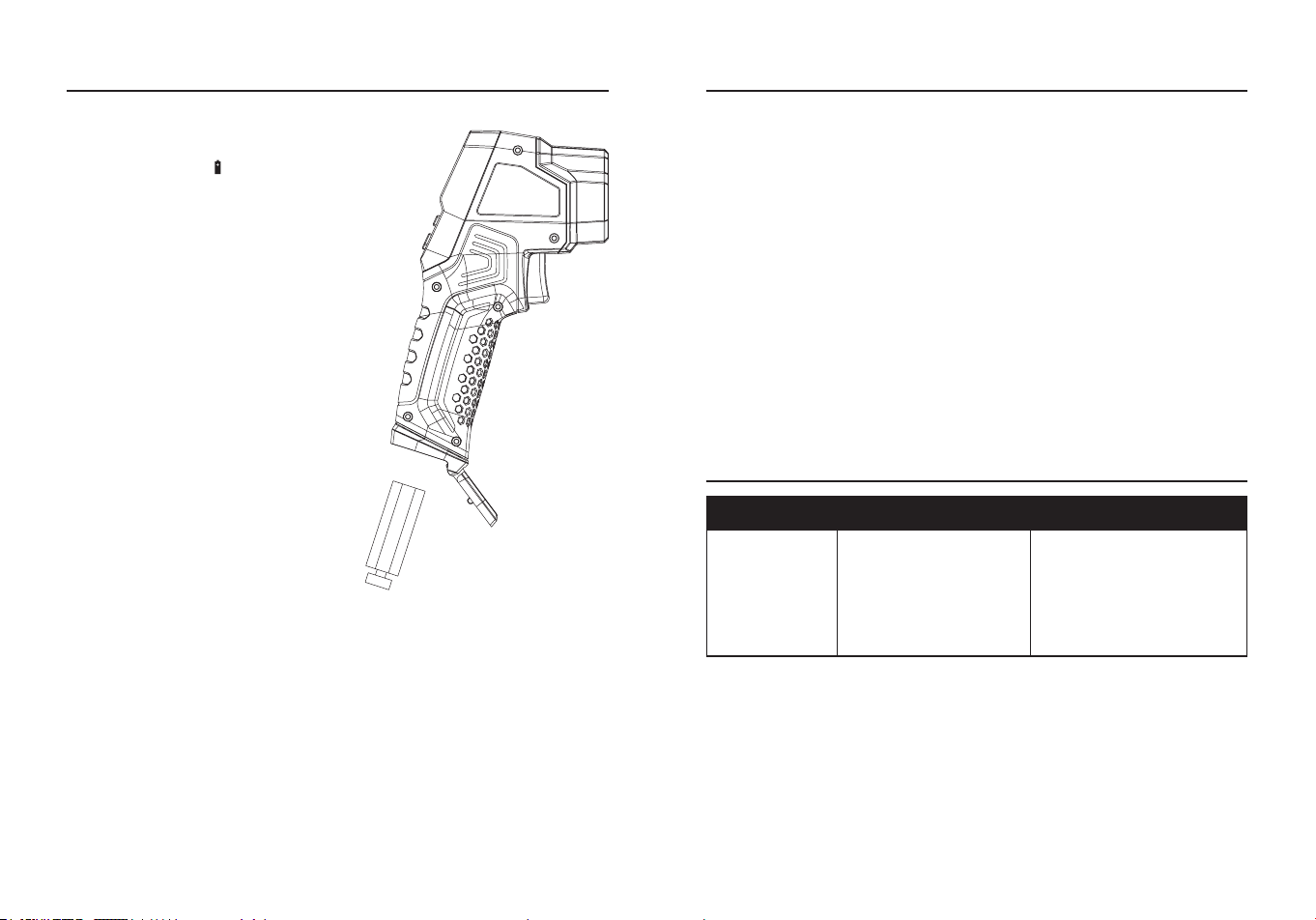
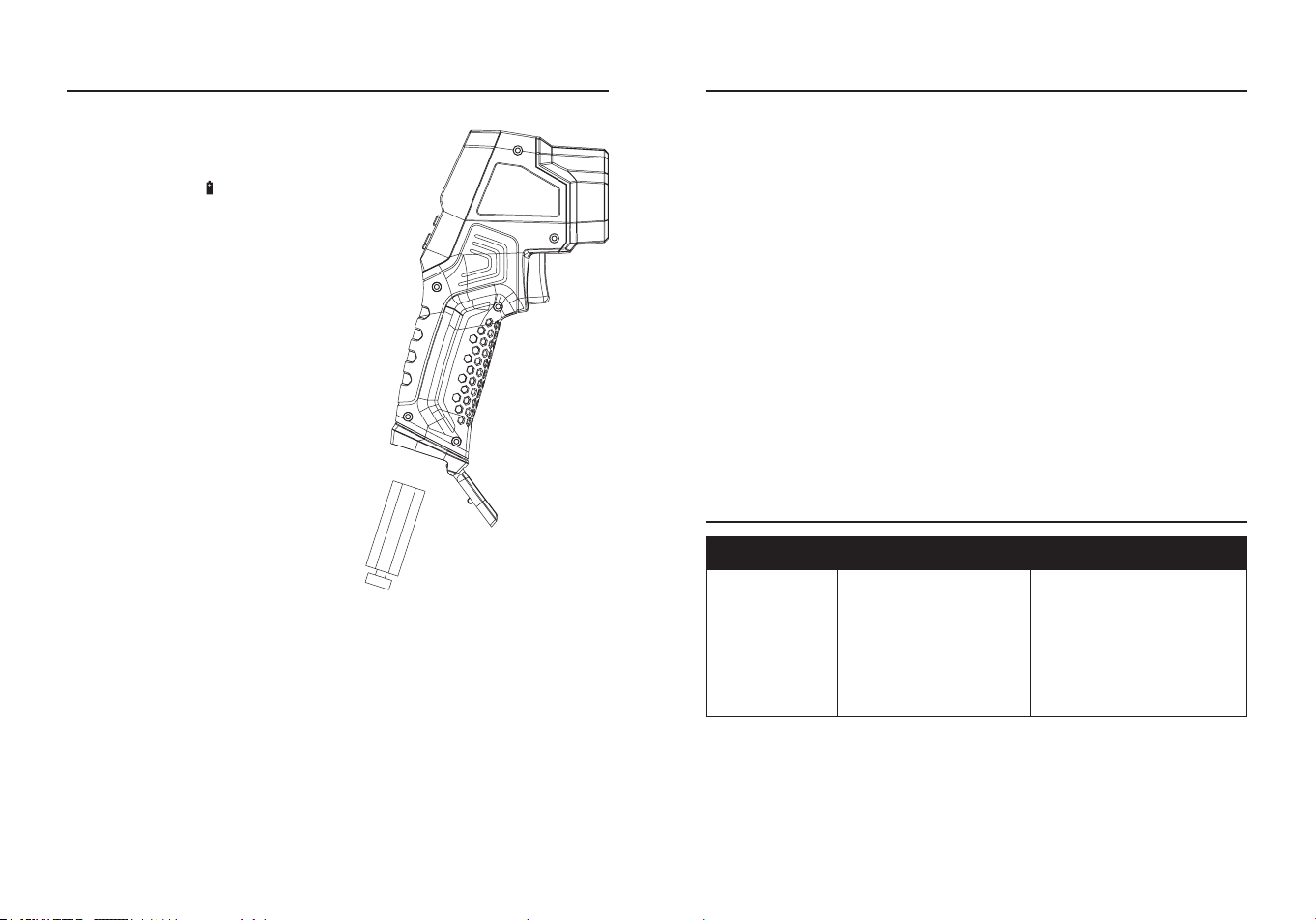
Battery Installation
●As battery power is not sucient,
LCD will display “ ” replacement
with new 9V battery type is
required.
●Open battery cover, then take
out the battery from instrument
and replace with new battery and
place the battery cover back.
OPERATING INSTRUCTIONS CARE AND MAINTENANCE
●Keep the meter dry. If it gets wet, wipe it o.
●Keep the meter clean. Wipe the dirt with a soft cloth dampened with
water. Do not use chemicals, cleaning solvents, or detergents.
●Use and store the meter in normal temperatures. Temperature
extremes can shorten the life of the electronic parts and distort or
melt plastic parts.
●Handle the meter gently and carefully. Dropping it can damage the
electronic parts or the case.
●Use only fresh batteries of the recommended size and type. Batteries
are to be inserted with the correct polarity. Remove old or weak
batteries so they do not leak and damage the unit.
●Do not mix old and new batteries. Do not mix dierent types of
batteries such as alkaline, carbon-zinc, or rechargeable batteries.
Non-rechargeable batteries are not to be recharged.
●If the meter is to be stored for a long period of time, the batteries
should be removed to prevent damage to the unit.
TROUBLESHOOTING
PROBLEM POSSIBLE CAUSE CORRECTIVE ACTION
No reading on
LCD display
1.Battery is weak.
2.The battery is not
properly installed.
3.The LCD / meter is
damaged.
1.Replace battery.
2.Install the battery
correctly according to
the polarity of the battery
compartment.
3.Replace meter.

14 15
PRODUCT SPECIFICATIONS
NCV Tester
GENERAL SPECIFICATIONS
Detection Voltage
Range
50 V to 1000 V AC
Frequency Range 50/60 Hz
Battery Two AAA 1.5 V batteries
Operating
Environment
32°F to 122°F (0°C to 50°C) at <80% relative
humidity
Storage Environment
14°F to 140°F (-10°C to 60°C) at <80%
relative humidity
Operating Altitude 6562 ft (2000 m) maximum
Net Weight Approx.0.07 lbs. (30 g)
Dimensions Approx.5.6x0.9x0.8 in. (142.5*24.5*21.2 mm)
Safety
Complies with UL 61010-1 for measurement
Category lV 1000 V, Pollution Degree 2
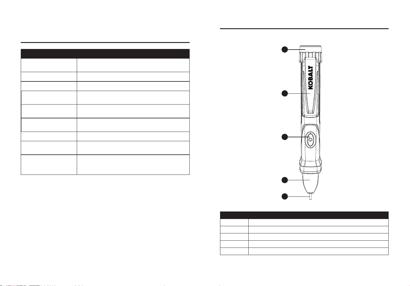
PACKAGE CONTENTS
PART DESCRIPTION
A Screw on battery cover
B Pocket clip
C Tester ON/OFF button
D LED indicator
E Detector tip
A
B
C
D
E
16 17
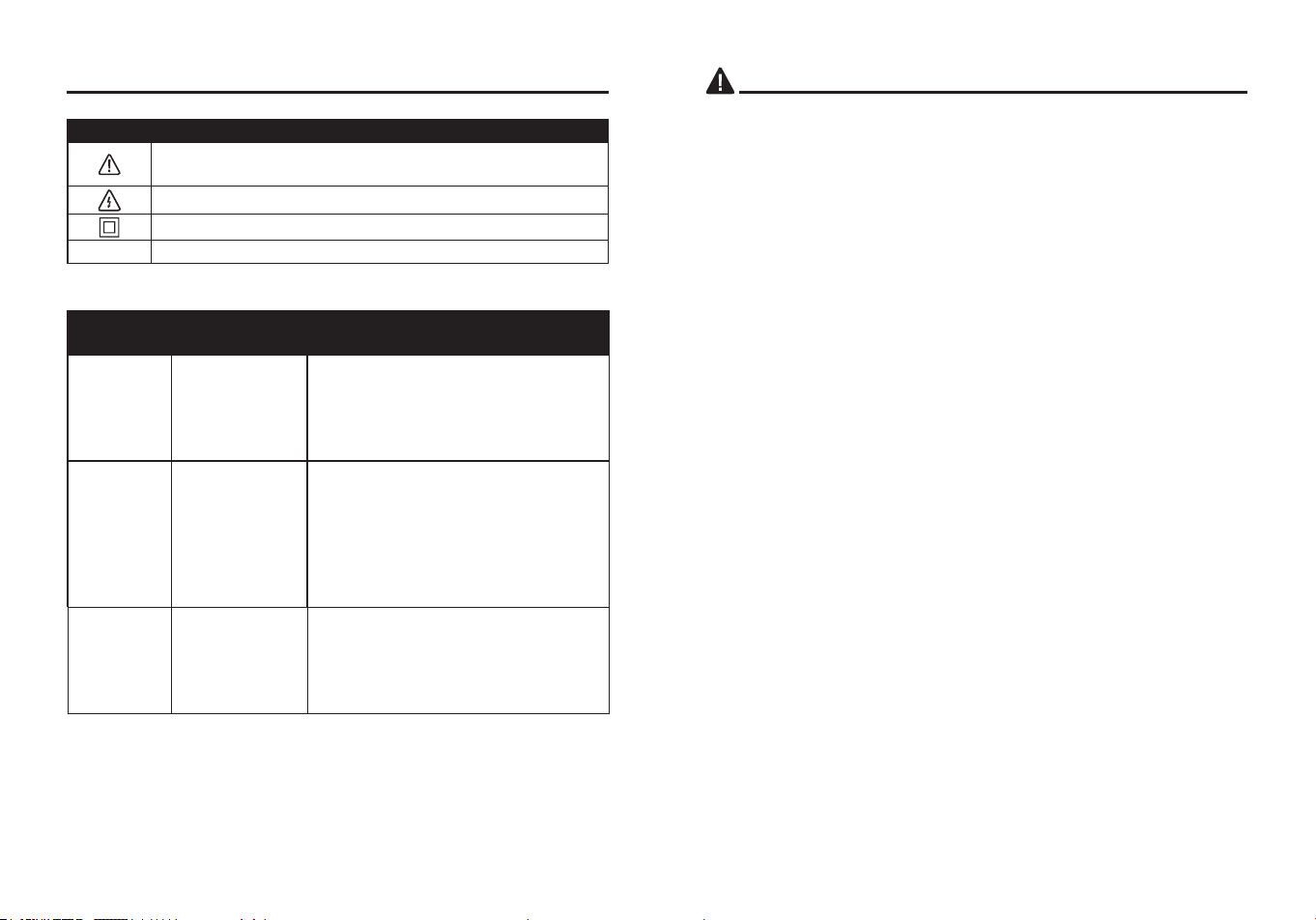
SYMBOLS
PART DESCRIPTION
Potential danger. Indicates the user must refer to the
manual for important safety information.
Indicates hazardous voltages may be present.
Equipment is protected by double or reinforced insulation.
V
Voltage
CATEGORY
RATING
BRIEF
DESCRIPTION
TYPICAL APPLICATIONS
CAT II
Single phase
receptacles
and connected
loads.
- Household appliances, power tools.
- Outlets more than 30ft (10m) from a
CAT III source.
- Outlets more than 60ft (20m) from a
CAT IV source.
CAT III
Three phase
circuits and
single phase
lighting circuits
in commercial
buildings.
- Equipment in xed installations such
as 3-phase motors, switchgear and
distribution panels - Lighting circuits
in commercial buildings.
- Feeder lines in industrial plants.
- Any device or branch circuit that is
close to a CAT III source.
CAT IV
Connection
point to
utility power
and outdoor
conductors.
-Primary distribution panels.
-Overhead or underground lines to
detached buildings.
-Incoming service entrance from utility
-Outdoor pumps.
Safety Category Ratings
The measurement category (CAT) rating and voltage rating is
determined by a combination of the meter, test probes and any
accessories connected to the meter and test probes. The combination
rating is the LOWEST of any individual component.
SAFETY INFORMATION
WARNING
●Please read and understand this entire manual before using this
product.
●The tester’s safety features may not protect the user if not used in
accordance with the manufacturer’s instructions.
●Check on a known live source within the rated AC voltage range of
the tester before use to ensure it is in working order.
●Insulation type and thickness, distance from the voltage source,
shielded wires, and other factors may aect reliable operation. Use
other methods to verify live voltage, if there is any uncertainty.
●Do not use if the tester appears damaged or if it is not operating
properly. If in doubt, replace the tester.
●Do not use on voltages that are higher than as marked on the tester.
●Use caution with voltages above 30 volts AC as a shock hazard may
exist.
●Comply with all applicable safety codes. Use approved personal
protective equipment when working near live electrical circuits-
particularly with regard to arc-ash potential.
●Do not operate tester if Low Battery warning occurs. Replace
batteries immediately.
●Do not use tester if there is evidence that batteries have leaked.
Tester may be compromised. Replace tester if this occurs.
●Use approved personal protective equipment when working on live
circuits.
●The detector will not detect voltage if:
-The voltage is DC.
-The wire is shielded or in a grounded metal box or conduit.
-The user is not grounded or is isolated from earth ground.
●The detector may not detect voltage if:
-The detector tip cannot be fully inserted into the electrical outlet.
-The electrical outlet is a Tamper Resistant (TR) design.
-The user is not holding the detector or the user’s hand is insulated
from the detector (i.e. with a glove).
-The voltage source or wire is partially buried.
18 19
"This device complies with part 15 of the FCC Rules. Operation is
subject to the following two conditions: (1) This device may not cause
harmful interference, and (2) this device must accept any interference
received, including interference that may cause undesired operation."
Lowe’s Home Centers LLC
1000 Lowe’s Blvd.
Mooresville, NC 28117
1-888-3KOBALT (1-888-356-2258)
This equipment has been tested and found to comply with the limits
for a Class B digital device, pursuant to part 15 of the FCC Rules.
These limits are designed to provide reasonable protection against
harmful interference in a residential installation. This equipment
generates, uses and can radiate radio frequency energy and, if not
installed and used in accordance with the instructions, may cause
harmful interference to radio communications. However, there is no
guarantee that interference will not occur in a particular installation. If
this equipment does cause harmful interference to radio or television
reception, which can be determined by turning the equipment o and
on, the user is encouraged to try to correct the interference by one or
more of the following measures:
- Reorient or relocate the receiving antenna.
- Increase the separation between the equipment and receiver.
- Connect the equipment into an outlet on a circuit dierent from that to
which the receiver is connected.
- Consult the dealer or an experienced radio/TV technician for help.
"
CAUTION
: Changes or modications not expressly approved by the
party responsible for compliance could void the user's authority to
operate the equipment."
Users of this product are cautioned not to make modications or
changes. Doing so may void the compliance of this product with
applicable laws and regulatory requirements and may result in the loss
of the user's authority to operate the equipment.
PRODUCT COMPLIANCE
NCV NCV,
IR Thermometer
Turning the Tester On and Self-test
●Momentarily press the tester ON/OFF button.
Self-test pass:
●The beeper will beep once and the green LED will ash twice
rapidly to indicate that the tester is on and ready for use.
●The tester will self-test every ve seconds when not detecting AC
voltage, the green LED will ash twice rapidly every self-test pass.
Self-test fail:
●The beeper will beep and all indicator LEDs will ash ve times,
and then turn o to indicate that the tester has failed.
Turning the Tester O
●Momentarily press the ON/OFF Button, The tester will beep twice
and all indicator LEDs will turn o to indicate the tester is o.
Turning the Beeper O
●With the tester o, press and hold the ON/OFF Button until the
green LED is illuminated, the tester will now operate without the
beeper.
Note
: The beeper cannot be turned o while the tester is on.
Verify Operation
●Before using tester, (1) Make sure the green LED is glowing, (2)
Check tester on a known live AC voltage that is within the dened
detection range of the tester.
AC Voltage Detection
●Place the tip of the tester near an AC voltage.
●If the tester detects voltage within the dened detection range, the
green LED will turn o, the red LED will turn on, and the beeper will
beep rapidly.
Low Battery Indication
●Replace the batteries if the green LED does not turn on.
●When the tester is on and the batteries are too low for reliable
operation, the beeper will beep three times and the green LED will
turn o indicating the tester is not operational.
●Replace the batteries to restore operation.
OPERATION INSTRUCTIONS
20 21
Auto Power O
●To extend battery life, the tester will automatically turn o after
approximately 5 minutes of inactivity.
●When powering down, the beeper will beep twice and all LEDs will
turn o.
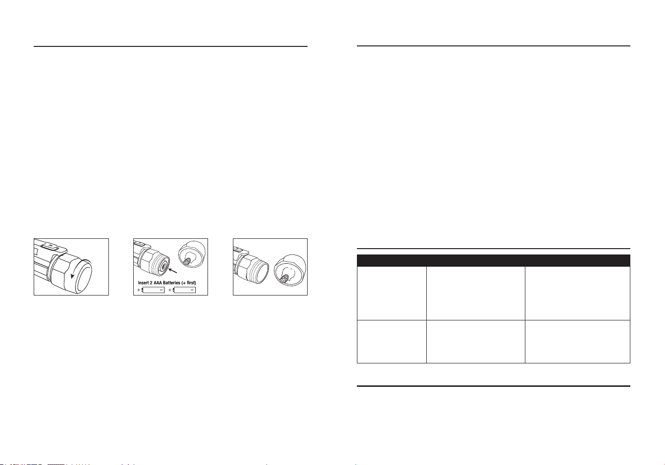
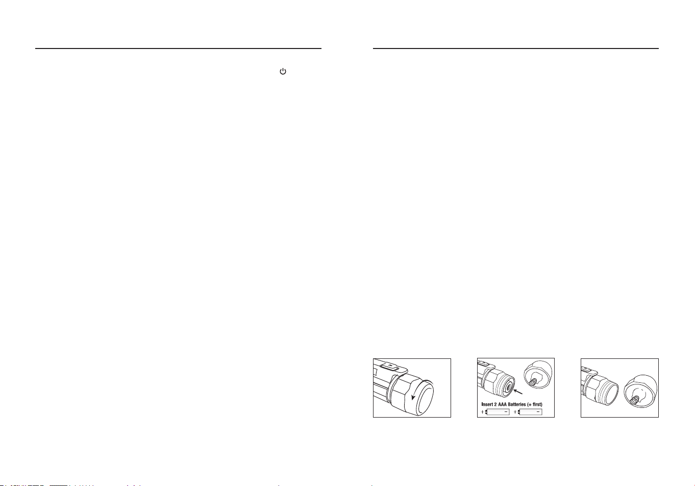
Battery Replacement
●Carefully unscrew battery cap at the rear of the tester.
●Replace batteries with two AAA 1.5 V batteries. Observe polarity.
●Screw cover onto tester until it feels tight. Do not use excessive force.
●Verify operation by using the tester on a known live AC voltage within
the dened detection range of the tester.
Unscrew battery cap Screw cap onto
tester
Observe correct
polarity when
installing batteries
OPERATION INSTRUCTIONS
NOTE:
The tester cannot determine the actual voltage. The voltage
level where the tester switches from the low to high voltage mode is
aected by insulation type and thickness, distance from the voltage
source, and other factors.
WARRANTY
Three-year warranty. Incidental or consequential damages are
excluded from this warranty.
Printed in China
CARE AND MAINTENANCE
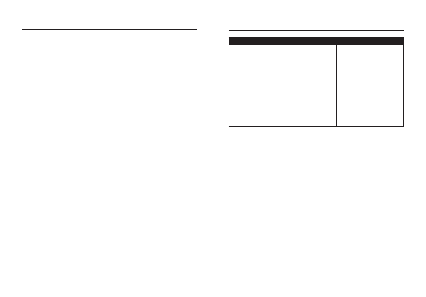
TROUBLESHOOTING
PROBLEM POSSIBLE CAUSE CORRECTIVE ACTION
Tester cannot
be turned on
1. Batteries are inserted
in the incorrect
polarity.
2. Batteries are weak.
1. Install batteries
observing polarity
shown inside battery
compartment.
2. Replace batteries.
The beeper
does not beep
when the red
LED is on
Working in silent mode.
Turn o the tester, then
momentarily press the
ON/OFF button to turn on
the tester.
●Keep the meter dry. If it gets wet, wipe it o.
●Keep the meter clean. Wipe the dirt with a soft cloth dampened with
water. Do not use chemicals, cleaning solvents, or detergents.
●Use and store the meter in normal temperatures. Temperature
extremes can shorten the life of the electronic parts and distort or
melt plastic parts.
●Handle the meter gently and carefully. Dropping it can damage the
electronic parts or the case.
●Use only fresh batteries of the recommended size and type. Batteries
are to be inserted with the correct polarity. Remove old or weak
batteries so they do not leak and damage the unit.
●Do not mix old and new batteries. Do not mix dierent types of
batteries such as alkaline, carbon-zinc, or rechargeable batteries.
Non-rechargeable batteries are not to be recharged.
●If the meter is to be stored for a long period of time, the batteries
should be removed to prevent damage to the unit.
23
ARTÍCULO #5995673
MODELO #DT-827Kit
TERMÓMETRO DE
INFRARROJOS CON
COMPROBADOR NCV
Número de serie
Fecha de compra
SG24723
KOBALT y el diseño del logotipo
son marcas comerciales o marcas
registradas de LF, LLC. Todos los
derechos reservados.
ADJUNTE AQUÍ SU RECIBO
Gracias por adquirir este producto KOBALT. ¿Tiene problemas
o le faltan piezas?
Antes de devolverlo, póngase en contacto con nosotros en:
888-356-2258
, 8:00 a 20:00, hora del Este, de lunes a domingo
o
ÍNDICE
Especicaciones del producto .........................................................24
Contenido del paquete ....................................................................26
Información de seguridad ................................................................29
Instrucciones de funcionamiento .....................................................30
Cuidado y mantenimiento ................................................................35
Resolución de problemas ................................................................35
Garantía...........................................................................................46
Comprobador de NCV
Especicaciones del producto .........................................................36
Contenido del paquete ....................................................................37
Información de seguridad ................................................................39
Instrucciones de funcionamiento .....................................................42
Cuidado y mantenimiento ................................................................44
Resolución de problemas ................................................................45
Garantía...........................................................................................46
Termómetro de infrarrojos sin contacto
24 25
Termómetro de infrarrojos sin contacto
ESPECIFICACIONES DEL PRODUCTO
ESPECIFICACIONES GENERALES
Rango de medida De -58 ºF a 1022 °F (de -50 ºC a 550 °C)
Unidades Congurable en °F o °C
Relación distancia al punto 12:1
Resolución de la pantalla 0,1°F/°C
Precisión
Supone una temperatura ambiente de
funcionamiento de 23 a 25 °C (73 a 77
°F)
±6,3 °F (3,5 °C) a -58 ºF a 68 ºF (-50 ºC
a 20 ºC)
±2,0 % o 3,6 °F (±2,0 °C) a 20 a 550 °C
(68 a 1022 °F)
Tiempo de respuesta <300 ms
Respuesta espectral 8~14 μm
Emisividad Ajustable digitalmente de 0,10 a 1,0
Visualización Pantalla LCD negativa
Indicación de exceso de
rango
La pantalla LCD mostrará “----”
Polaridad
Automático (sin indicación para polaridad
positiva); signo menos (-) para polaridad
negativa
Láser de puntería Puntería láser única
Láser de diodo
Salida <1 mW, Longitud de onda
630~670 nm, Producto láser de clase 2
Batería 1 pila de 9 V
Temperatura de
funcionamiento
32 °F a 122 °F (0 °C a 50 °C)
Temperatura de
almacenamiento
-4 °F a 122 °F (-20 °C a 50 °C)
Humedad relativa
Humedad relativa (HR) de 10 % a
90 % en funcionamiento, <80 % en
almacenamiento
Altitud de funcionamiento 7000 pies (2000 m) máximo
Peso neto Aprox. 0,36 libras (164 g)
Dimensiones
92 x 45 x 173 mm (3,62 x 1,77 x 6,81
pulg.)
Seguridad IEC EN 60825-1, EN 50689
Nota:
Campo de visión: Asegúrese de que el objetivo es mayor que el
tamaño del punto de mira de la unidad. Cuanto más pequeño sea el
objetivo, más cerca deberá estar de él. Cuando la precisión sea crítica,
asegúrese de que el blanco es al menos el doble de grande que el
tamaño del punto.
Nota:
Este equipo cumple con la norma EN 50689 (Seguridad de los
productos láser - Particularidades de los productos láser de consumo).
26 27
CONTENIDO DEL PAQUETECONTENIDO DEL PAQUETE
PIEZA DESCRIPCIÓN
A Pantalla LCD
B Botón Arriba (para Emisividad, Alarma Alta, Alarma Baja)
C Botón Abajo (para Emisividad, Alarma Alta, Alarma Baja)
D Botón MODO (para recorrer el bucle de modos)
E Oricio del láser
F Sensor IR
G Disparador de medición
H Tapa de las pilas
B
C
D
A
E
F
G
H
PIEZA DESCRIPCIÓN CANTIDAD
A Termómetro infrarrojo DT-826B 1
B Probador NCV 1
C Estuche de transporte 1
D Batería de 9 voltios (Termómetro infrarrojo) 1
E Batería de 1.5 voltios (Probador NCV) 2
A
B E
C D

28 29
CONTENIDO DEL PAQUETE
PIEZA DESCRIPCIÓN
A Escanear
B Retención de datos
C Láser encendido
D Alarma alta y alarma baja
E °C/°F
F Baja potencia
G Emisividad
H Valor de emisividad
I Valores de temperatura para los MAX/MIN/DIF/AVG
J Símbolos para MAX/MIN/DIF/AVG
K Valor de temperatura actual
A
B
C
D
E
F
G
H
I
J
K
INFORMACIÓN DE SEGURIDAD
ADVERTENCIAS
●No utilizar con nes médicos.
●Manténgalo fuera del alcance de los niños.
●No abra la carcasa salvo el compartimento de las pilas.
●Evite la exposición directa de los ojos.
●No exponga la herramienta a gases o vapores explosivos ni a la
lluvia o condiciones húmedas.
●Manténgase alerta, observe lo que hace y utilice el sentido común
cuando maneje la herramienta. No la utilice cuando esté cansado o
bajo los efectos de drogas, alcohol o medicamentos. Un momento de
falta de atención puede provocar lesiones personales graves.
●Utilice la herramienta de acuerdo con estas instrucciones, teniendo
en cuenta las condiciones de trabajo y el trabajo a realizar. El uso
de la herramienta para operaciones distintas de las previstas podría
resultar en una situación de peligro.
●Encargue el mantenimiento de su herramienta a un técnico calicado,
utilizando únicamente piezas de repuesto idénticas. Esto garantizará
el mantenimiento de la seguridad de la herramienta.
●No utilice la herramienta si funciona de forma incorrecta o anormal o
si está dañada.
●ANTES DE CADA USO, inspeccione el estado general de la
herramienta. Compruebe:
- materiales sueltos.
- desalineación o atascamiento de piezas.
- piezas agrietadas o rotas,
- cableado eléctrico dañado,
- cualquier otra condición que pueda afectar a su funcionamiento seguro.
●Extreme las precauciones cuando el rayo láser esté encendido.
●No deje que el rayo entre en su
ojo, en el ojo de otra persona o
en el ojo de un animal.
●Tenga cuidado de no dejar que
el haz sobre una supercie
reectante incida en su ojo.
●No deje que el haz de luz láser
incida sobre ningún gas que
pueda explotar.
RAYONNEMENT LASER NE REGARDEZ PAS LE FAISCEAU.
30 31
INSTRUCCIONES DE FUNCIONAMIENTO
Distancia y tamaño del punto
●A medida que aumenta la distancia (D) al objeto, aumenta el tamaño
puntual (S) del área medida por la unidad.
●A continuación se indica la relación entre la distancia y el tamaño del
punto para cada unidad.
●Los tamaños de punto indican el 90 % de energía rodeada.
Cómo funciona
●Los termómetros de infrarrojos miden la temperatura de la supercie
de un objeto.
●La óptica del aparato detecta la energía emitida, reejada y
transmitida, que se recoge y enfoca en un detector.
●La electrónica de la unidad traduce la información en una lectura de
temperatura, que se muestra en la unidad.
●El láser se utiliza únicamente para apuntar.
Campo de visión
●Asegúrese de que el blanco es mayor que el tamaño del punto de
mira de la unidad; cuanto más pequeño sea el blanco, más cerca
deberá estar de él.
●Cuando la precisión sea crítica, asegúrese de que el objetivo es al
menos el doble de grande que el tamaño del punto.
Localización de un punto caliente
●Para encontrar un punto caliente apunte con el termómetro fuera del
área de interés, luego escanee a través con un movimiento hacia
arriba y hacia abajo hasta que localice el punto caliente.
D
S
0.5@6 pulg.
1.0@12 pulg.
12.5@152 mm
25@305 mm
Distancia : Punto = 12:1
INSTRUCCIONES DE FUNCIONAMIENTO
Función de los botones
●Botón Arriba para encender o apagar el láser,
●Pulse brevemente el botón MODO para cambiar MAX/MIN/DIF/AVG.
●Para ajustar los valores de Alarma Alta (HAL), Alarma Baja (LAL) y
Emisividad (EMS), mantenga pulsado el Botón MODO hasta que
aparezca el código correspondiente en la pantalla, pulse los Botones
Arriba y Abajo para ajustar los valores deseados.
°C/°F
●Pulse el botón Arriba/Abajo para cambiar la unidad de temperatura (°C
o °F).
HAL (BAJA) encendido/apagado
●Pulse el botón Arriba o Abajo para encender o apagar.
●Pulse el disparador de medición para conrmar el modo de alarma
Alta (Baja).
Ajuste HAL (BAJA)
●La alarma Alta (Baja) ajustable de -50 a 550 °C (-58 a 1022 °F).
Visualización MAX/MIN/DIF/AVG
MAX/MIN/DIF/AVG indican el registro MAX/MIN/DIF/AVG que se
visualiza entre la pulsación y la liberación del botón "encendido/
apagado" cada vez.
MAX=Máximo, Valor máximo medido.
MIN=Mínimo, Valor mínimo medido.
Botón MODO
●Pulsando el botón MODO también podrá acceder al estado de ajuste,
Emisividad (EMS), °C/°F, HAL Encendido/Apagado, ajuste HAL BAJA
Encendido/Apagado, ajuste BAJA.
●Cada vez que pulse "establecer" avanzará por el ciclo de modo.
●El diagrama muestra la secuencia de funciones en el ciclo de modo.
32 33
INSTRUCCIONES DE FUNCIONAMIENTO
Sustancia
Emisividad
térmica
Sustancia
Emisividad
térmica
Asfalto 0,90 a 0,98 Tela (negra) 0,98
Hormigón 0,94 Piel humana 0,98
Cemento 0,96 Espuma 0,75 a 0,80
Arena 0,90 Carbón vegetal (polvo) 0,96
Tierra 0,92 a 0,96 Laca 0,80 a 0,95
Agua 0,92 a 0,96 Laca (mate) 0,97
Hielo 0,96 a 0,98 Goma (negra) 0,94
Nieve 0,83 Plástico 0,85 a 0,95
Vidrio 0,90 a 0,95 Madera 0,90
Cerámica 0,90 a 0,94 Papel 0,70 a 0,94
Mármol 0,94 Óxidos de cromo 0,81
Yeso 0,80 a 0,90 Óxidos de cobre 0,78
Mortero 0,89 a 0,91 Óxidos de hierro 0,78 a 0,82
Ladrillo 0,93 a 0,96 Textiles 0,90
●Para compensar, cubra la supercie a medir con cinta adhesiva o
pintura negra plana, deje tiempo para que la cinta alcance la misma
temperatura que el material que tiene debajo, mida la temperatura de
la cinta o de la supercie pintada.
Emisividad
●La emisividad es un término utilizado para describir las características
de emisión de energía de los materiales.
●La mayoría (90 % de las aplicaciones típicas) de los materiales
orgánicos y las supercies pintadas u oxidadas tienen una emisividad
de 0,95 (preajustada en el aparato).
●Se obtendrán lecturas imprecisas al medir supercies metálicas
brillantes o pulidas.
DIF=Diferencia, Valor de diferencia entre los valores máximo y mínimo
medidos.
AVG=Promedio, Valor promedio medido.
Funcionamiento de la medición
●Apúntelo hacia la supercie a medir. Jale y sostenga el gatillo para
encender el medidor y comenzar la prueba.
La pantalla se iluminará si la pila está en buen estado, sustituya la
pila si la pantalla no se ilumina.
●Suelte el gatillo y el ícono MANTENER aparecerá en la pantalla LCD
indicando que la lectura está siendo retenida.
En el estado MANTENER, pulse el botón Arriba para encender o
apagar el láser, y pulse el botón Abajo para encender o apagar la
retroiluminación.
●El medidor se apagará automáticamente transcurridos
aproximadamente 10 segundos después de soltar el gatillo (a menos
que la unidad esté bloqueada).
Notas de medida
●Apunte con el sensor IR directamente al objeto objetivo. El medidor
compensa automáticamente las desviaciones de temperatura
respecto a la temperatura ambiente.
●Tenga en cuenta que tardará hasta 30 minutos en ajustarse a
temperaturas ambiente amplias. Se necesita algo de tiempo (varios
minutos) después de realizar las mediciones de temperatura baja (y
antes de las altas).
●Esto es consecuencia del proceso de enfriamiento, que debe tener
lugar para el sensor IR.
INSTRUCCIONES DE FUNCIONAMIENTO
34 35
Instalación de la batería
●Como la energía de la batería
no es suciente, la pantalla
LCD mostrará " " es necesario
sustituirla por una batería nueva
de 9 V.
●Abra la tapa de la batería,
saque la pila del instrumento
y sustitúyala por una nueva y
vuelva a colocar la tapa de la
batería.
INSTRUCCIONES DE FUNCIONAMIENTO CUIDADO Y MANTENIMIENTO
●Mantenga el medidor seco. Si se moja, límpielo con un paño.
●Mantenga limpio el medidor. Limpie la suciedad con un paño suave
humedecido con agua. No utilice productos químicos, disolventes de
limpieza ni detergentes.
●Utilice y guarde el medidor a temperaturas normales. Las
temperaturas extremas pueden acortar la vida útil de las piezas
electrónicas y deformar o fundir las piezas de plástico.
●Manipule el medidor con suavidad y cuidado. Dejarlo caer puede
dañar las piezas electrónicas o la carcasa.
●Utilice únicamente pilas nuevas del tamaño y tipo recomendados.
Las pilas deben colocarse con la polaridad correcta. Retire las pilas
viejas o débiles para que no se derramen y dañen la unidad.
●No mezcle pilas viejas y nuevas. No mezcle diferentes tipos de pilas
como las alcalinas, las de carbono-zinc o las recargables. Las pilas
no recargables no deben recargarse.
●Si se va a almacenar el medidor durante un largo periodo de tiempo,
deben extraerse las pilas para evitar daños en la unidad.
RESOLUCIÓN DE PROBLEMAS
PROBLEMA POSIBLE CAUSA ACCIÓN CORRECTIVA
No hay lectura
en la pantalla
LCD
1. La batería está débil.
2. La batería no
está instalada
correctamente.
3. La pantalla LCD/
medidor está dañado.
1. Sustituya la batería.
2. Instale la batería
correctamente según
la polaridad del
compartimento de la
batería.
3. Sustituya el medidor.
36 37
ESPECIFICACIONES DEL PRODUCTO
Probador NCV
ESPECIFICACIONES GENERALES
Rango de tensión de
detección
50 V a 1000 V de CA
Rango de frecuencia 50/60 Hz
Batería Dos pilas AAA de 1,5 V
Entorno de
funcionamiento
De 0 °C a 50 °C (32 °F a 122 °F) a <80 % de
humedad relativa
Entorno de
almacenamiento
14 °F a 140 °F (-10 °C a 60 °C) a <80 % de
humedad relativa
Altitud de
funcionamiento
6562 pies (2000 m) máximo
Peso neto Aprox. 0,07 libras (30 g)
Dimensiones
Aprox. 5,6x0,9x0,8 pulg.
(142.5*24.5*21.2 mm)
Seguridad
Cumple la norma UL 61010-1 para
mediciones Categoría lV 1000 V, Grado de
contaminación 2
CONTENIDO DEL PAQUETE
PARTE DESCRIPCIÓN
A Tapa de la batería atornillada
B Clip de bolsillo
C Botón de encendido/apagado del comprobador
D Indicador LED
E Punta detectora
A
B
C
D
E
38 39
SÍMBOLOS
PARTE DESCRIPCIÓN
Peligro potencial. Indica que el usuario debe consultar el
manual para obtener información de seguridad importante.
Indica que puede haber tensiones peligrosas.
El equipo está protegido por un aislamiento doble o
reforzado.
V
Tensión
CLASIFICACIÓN
POR
CATEGORÍAS
BREVE
DESCRIPCIÓN
APLICACIONES TÍPICAS
CAT II
Receptáculos
monofásicos
y cargas
conectadas.
-Electrodomésticos, herramientas
eléctricas.
-Enchufes a más de 10 m (30 pies)
de una fuente CAT III.
Enchufes a más de 20 m (60 pies)
de una fuente CAT IV.
CAT III
Circuitos
trifásicos y
circuitos de
iluminación
monofásicos
en edicios
comerciales.
-Equipos en instalaciones
jas como motores trifásicos,
aparamenta y cuadros de
distribución - Circuitos de
alumbrado en edicios
comerciales.
-Líneas de alimentación en plantas
industriales.
Cualquier dispositivo o circuito
derivado que esté cerca de una
fuente CAT III.
CAT IV
Punto de
conexión a la
red eléctrica y
conductores
exteriores.
- Cuadros de distribución primaria.
- Líneas aéreas o subterráneas a
edicios independientes.
- Entrada de servicio de la
compañía eléctrica.
- Bombas exteriores.
Clasicaciones de las categorías de seguridad
La clasicación de la categoría de medición (CAT) y la clasicación de
la tensión vienen determinadas por la combinación del medidor, las
puntas de prueba y cualquier accesorio conectado al medidor y a las
puntas de prueba. La clasicación de la combinación es la MÁS BAJA
de cualquier componente individual.
INFORMACIÓN DE SEGURIDAD
ADVERTENCIA
●Lea y comprenda todo este manual antes de utilizar este producto.
●Las funciones de seguridad del comprobador pueden no proteger
al usuario si no se utiliza de acuerdo con las instrucciones del
fabricante.
●Compruebe en una fuente viva conocida dentro del rango de tensión
de CA nominal del comprobador antes de utilizarlo para asegurarse
de que funciona correctamente.
●El tipo y grosor del aislamiento, la distancia a la fuente de tensión, los
cables apantallados y otros factores pueden afectar a la abilidad del
funcionamiento. Utilice otros métodos para vericar la tensión viva, si
existe alguna incertidumbre.
●No lo utilice si el comprobador parece dañado o si no funciona
correctamente. En caso de duda, sustituya el comprobador.
●No lo utilice con tensiones superiores a las marcadas en el
comprobador.
●Tenga cuidado con las tensiones superiores a 30 voltios de CA, ya
que puede existir riesgo de descarga eléctrica.
●Cumpla todos los códigos de seguridad aplicables. Utilice equipo de
protección personal homologado cuando trabaje cerca de circuitos
eléctricos en tensión, especialmente en lo que se reere al potencial
de arco eléctrico.
●No utilice el comprobador si aparece el aviso de pilas bajas. Sustituya
las pilas inmediatamente.
●No utilice el comprobador si hay indicios de que las pilas tienen fugas.
El comprobador puede estar en peligro. Sustituya el comprobador si
esto ocurre.
●Utilice equipo de protección personal homologado cuando trabaje en
circuitos con tensión.
40 41
●El detector no detectará tensión si:
-La tensión es continua.
-El cable está apantallado o en una caja o conducto metálico con
toma de tierra.
-El usuario no está conectado a tierra o está aislado de la toma de
tierra.
●Es posible que el detector no detecte tensión si:
-La punta del detector no puede introducirse completamente en la
toma eléctrica.
-La toma eléctrica tiene un diseño a prueba de manipulaciones
(TR).
-El usuario no está sujetando el detector o la mano del usuario
está aislada del detector (por ejemplo, con un guante).
-La fuente de tensión o el cable están parcialmente enterrados.
"Este aparato cumple con la parte 15 de las normas FCC. Su
funcionamiento está sujeto a las dos condiciones siguientes: (1) Este
dispositivo no puede causar interferencias perjudiciales, y (2) este
dispositivo debe aceptar cualquier interferencia recibida, incluidas las
interferencias que puedan causar un funcionamiento no deseado".
Lowe’s Home Centers LLC 1000 Lowe’s Blvd.
Mooresville, NC 28117
1-888-3KOBALT (1-888-356-2258)
Se advierte a los usuarios de este producto que no realicen
modicaciones ni cambios. Hacerlo puede anular la conformidad de
este producto con las leyes y requisitos reglamentarios aplicables y
puede dar lugar a la pérdida de la autoridad del usuario para utilizar el
equipo.
CONFORMIDAD DEL PRODUCTO
NCV NCV,
IR Thermometer
Este equipo ha sido sometido a pruebas y se ha comprobado que
cumple los límites establecidos para un dispositivo digital de Clase
B, de conformidad con la parte 15 de las normas de la FCC. Estos
límites están diseñados para proporcionar una protección razonable
contra interferencias perjudiciales en una instalación residencial. Este
equipo genera, utiliza y puede irradiar energía de radiofrecuencia
y, si no se instala y utiliza de acuerdo con las instrucciones, puede
causar interferencias perjudiciales en las comunicaciones por radio.
Sin embargo, no existe ninguna garantía de que no se produzcan
interferencias en una instalación concreta. Si este equipo causa
interferencias perjudiciales en la recepción de radio o televisión,
lo que puede determinarse apagando y encendiendo el equipo, se
recomienda al usuario que intente corregir las interferencias mediante
una o varias de las siguientes medidas:
-Reoriente o reubique la antena receptora.
-Aumente la separación entre el equipo y el receptor.
-Conecte el equipo a una toma de corriente de un circuito distinto al
que está conectado el receptor.
-Consulte al distribuidor o a un técnico experto en radio/TV para
obtener ayuda.
"
PRECAUCIÓN
: Los cambios o modicaciones no aprobados
expresamente por la parte responsable del cumplimiento podrían
anular la autoridad del usuario para utilizar el equipo".
42 43
Encendido del comprobador y autocomprobación
● Pulse momentáneamente el botón de encendido/apagado del
comprobador.
Autocomprobación superada:
●El avisador emitirá un pitido y el LED verde parpadeará dos veces
rápidamente para indicar que la comprobadora está encendida y
lista para su uso.
●El comprobador se autocomprobará cada cinco segundos cuando
no detecte tensión de CA, el LED verde parpadeará dos veces
rápidamente cada vez que pase la autocomprobación.
Fallo en la autocomprobación:
●El avisador emitirá un pitido y todos los indicadores LED
parpadearán cinco veces, y luego se apagarán para indicar que el
comprobador ha fallado.
Apagado del comprobador
● Pulse momentáneamente el botón de encendido/apagado, el
comprobador emitirá dos pitidos y todos los indicadores LED se
apagarán para indicar que el comprobador está apagado.
Apagar el avisador acústico
●Con el comprobador apagado, mantenga pulsado el botón
de encendido/apagado hasta que se ilumine el LED verde. El
comprobador funcionará ahora sin la señal acústica.
Nota:
La señal acústica no puede apagarse mientras el comprobador
está encendido.
Vericar el funcionamiento
●Antes de utilizar el comprobador, (1) asegúrese de que el LED verde
está encendido (2) verique el comprobador en una tensión alterna
viva conocida que esté dentro del rango de detección denido del
comprobador.
Detección de tensión alterna
●Coloque la punta del comprobador cerca de una tensión alterna.
●Si el comprobador detecta tensión dentro del rango de detección
denido, el LED verde se apagará, el LED rojo se encenderá y el
avisador emitirá un pitido rápido.
INSTRUCCIONES DE FUNCIONAMIENTO
Indicación de batería baja
●Sustituya las pilas si el LED verde no se enciende.
●Cuando el comprobador está encendido y las pilas están demasiado
bajas para un funcionamiento conable, el avisador emitirá tres
pitidos y el LED verde se apagará indicando que el comprobador no
está operativo.
●Sustituya las pilas para restablecer el funcionamiento.
Apagado automático
●Para prolongar la duración de la batería, el comprobador se apagará
automáticamente después de aproximadamente 5 minutos de
inactividad.
●Al apagarse, el avisador emitirá dos pitidos y todos los LED se
apagarán.
INSTRUCCIONES DE FUNCIONAMIENTO
Sustitución de las pilas
●Desenrosque con cuidado la tapa de la batería situada en la parte
posterior del comprobador.
●Sustituya las pilas por dos pilas AAA de 1,5 V. Observe la polaridad.
●Enrosque la tapa en el comprobador hasta que quede bien apretada.
No ejerza una fuerza excesiva.
●Verique el funcionamiento utilizando el comprobador con una
tensión alterna viva conocida dentro del rango de detección denido
del comprobador.
Desenrosque la
tapa de la batería
Enrosque la tapa
en el comprobador
Respete la polaridad
correcta al instalar las
baterías
NOTA:
El comprobador no puede determinar la tensión real. El nivel de
tensión en el que el comprobador pasa del modo de baja a alta tensión
se ve afectado por el tipo y el grosor del aislamiento, la distancia a la
fuente de tensión y otros factores.
44 45
CUIDADO Y MANTENIMIENTO RESOLUCIÓN DE PROBLEMAS
PROBLEMA POSIBLE CAUSA ACCIÓN CORRECTIVA
El comprobador
no puede
encenderse
1.Las pilas están
colocadas con la
polaridad incorrecta.
2.Las pilas están
débiles.
1.Instale las pilas
respetando la polaridad
indicada en el interior
del compartimento de
las pilas.
2.Sustituya las pilas.
El avisador
acústico no
pita cuando el
LED rojo está
encendido
Trabajando en modo
silencioso.
Apague el comprobador
y, a continuación, pulse
momentáneamente el
botón de encendido
y apagado para
encenderlo.
●Mantenga el medidor seco. Si se moja, límpielo con un paño.
●Mantenga limpio el medidor. Limpie la suciedad con un paño suave
humedecido con agua. No utilice productos químicos, disolventes de
limpieza ni detergentes.
●Utilice y guarde el medidor a temperaturas normales. Las
temperaturas extremas pueden acortar la vida útil de las piezas
electrónicas y deformar o fundir las piezas de plástico.
●Manipule el medidor con suavidad y cuidado. Dejarlo caer puede
dañar las piezas electrónicas o la carcasa.
●Utilice solo pilas nuevas del tamaño y tipo recomendados. Las pilas
deben colocarse con la polaridad correcta. Retire las pilas viejas o
débiles para que no se derramen y dañen el aparato.
●No mezcle pilas viejas y nuevas. No mezcle diferentes tipos de pilas
como las alcalinas, las de carbono-zinc o las recargables. Las pilas
no recargables no deben recargarse.
●Si el medidor va a estar almacenado durante un periodo de tiempo
prolongado, deben extraerse las pilas para evitar daños en la unidad.

46
GARANTÍA
Tres años de garantía. Quedan excluidos de esta garantía los daños
incidentales o consecuentes.
Impreso en China