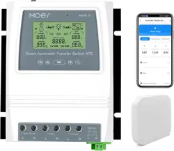
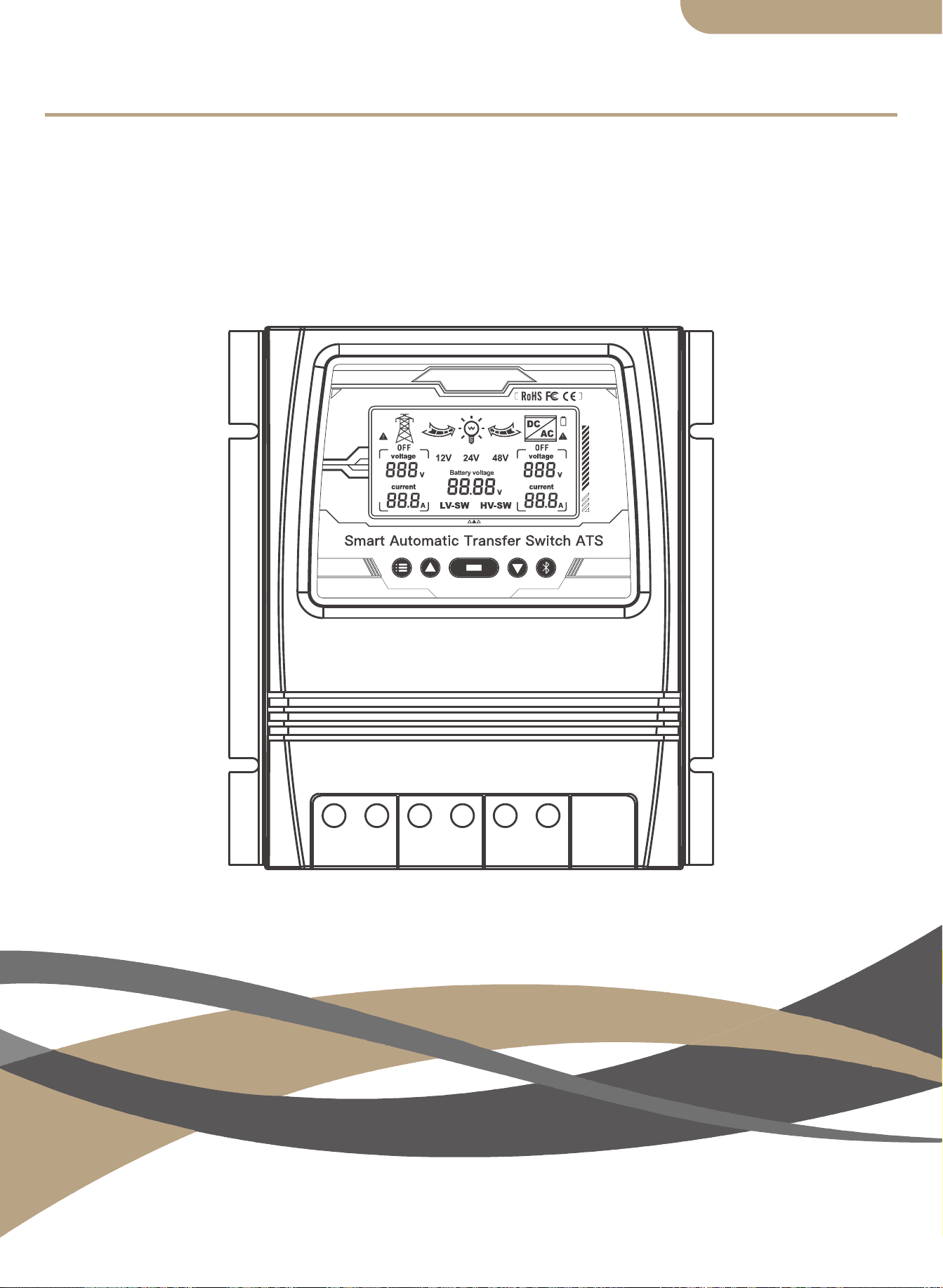
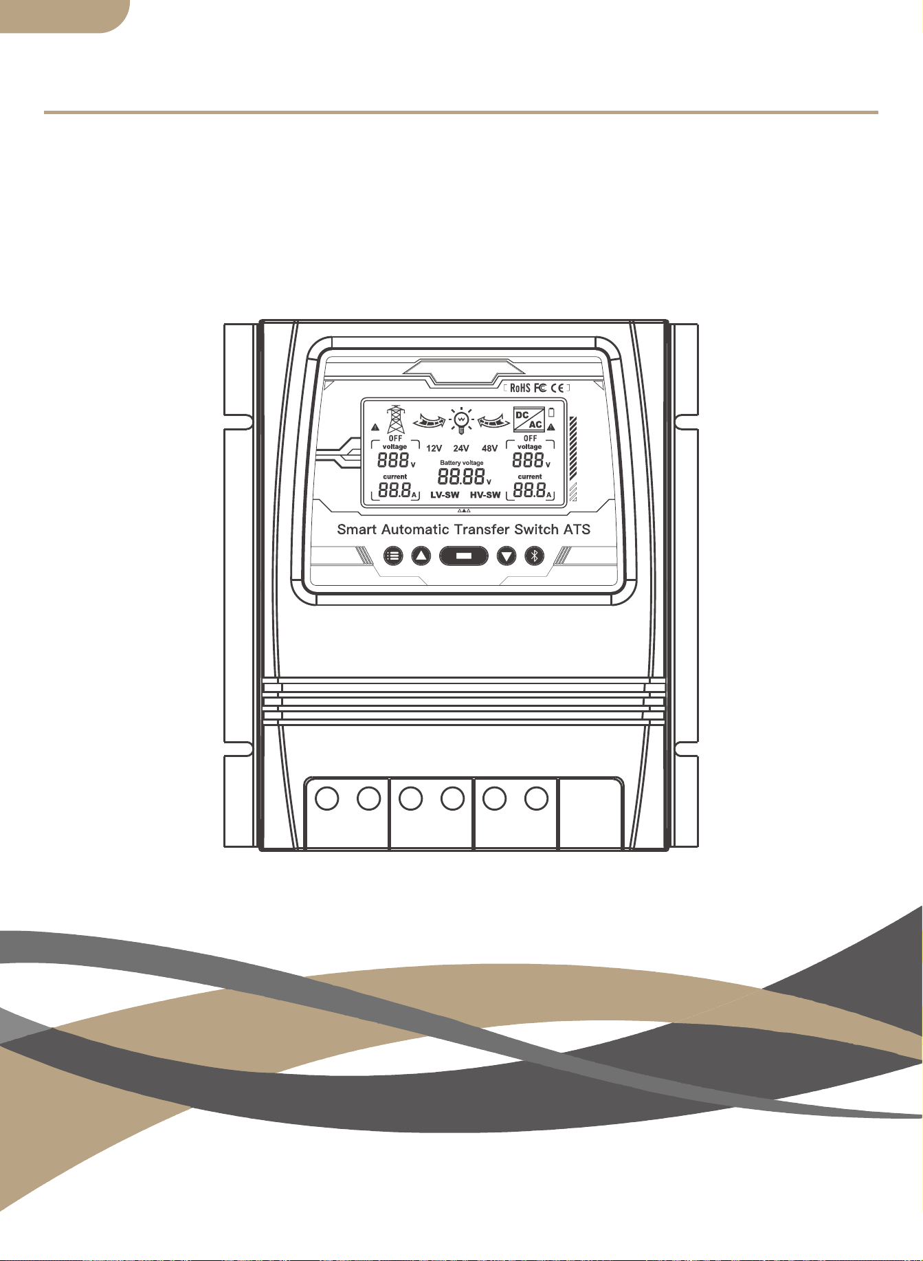
Smart Automatic Transfer Switch ATS
User Manual
HOME,SMART MOES HOME

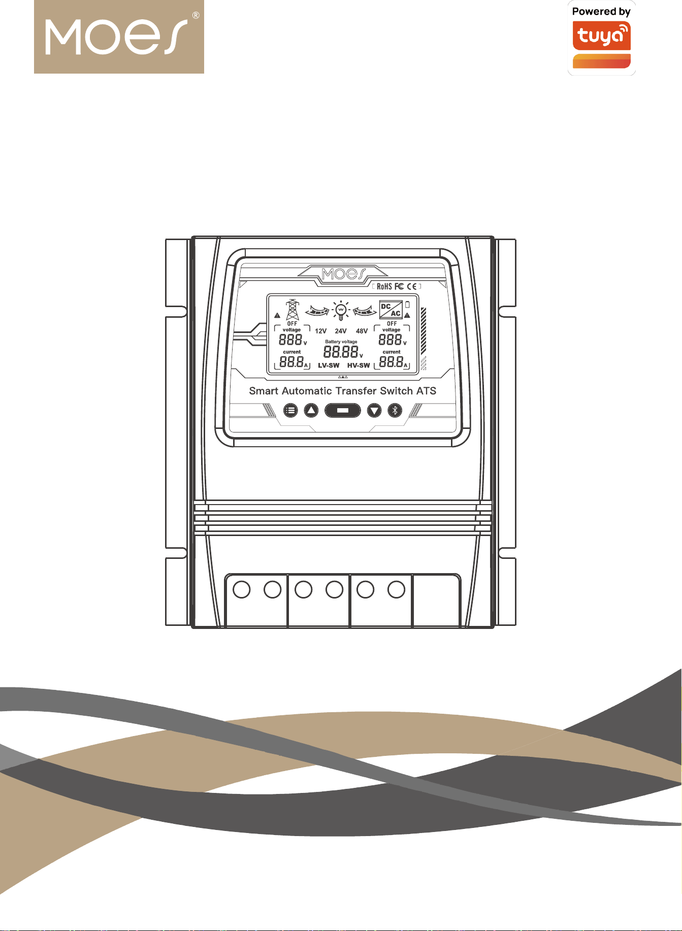
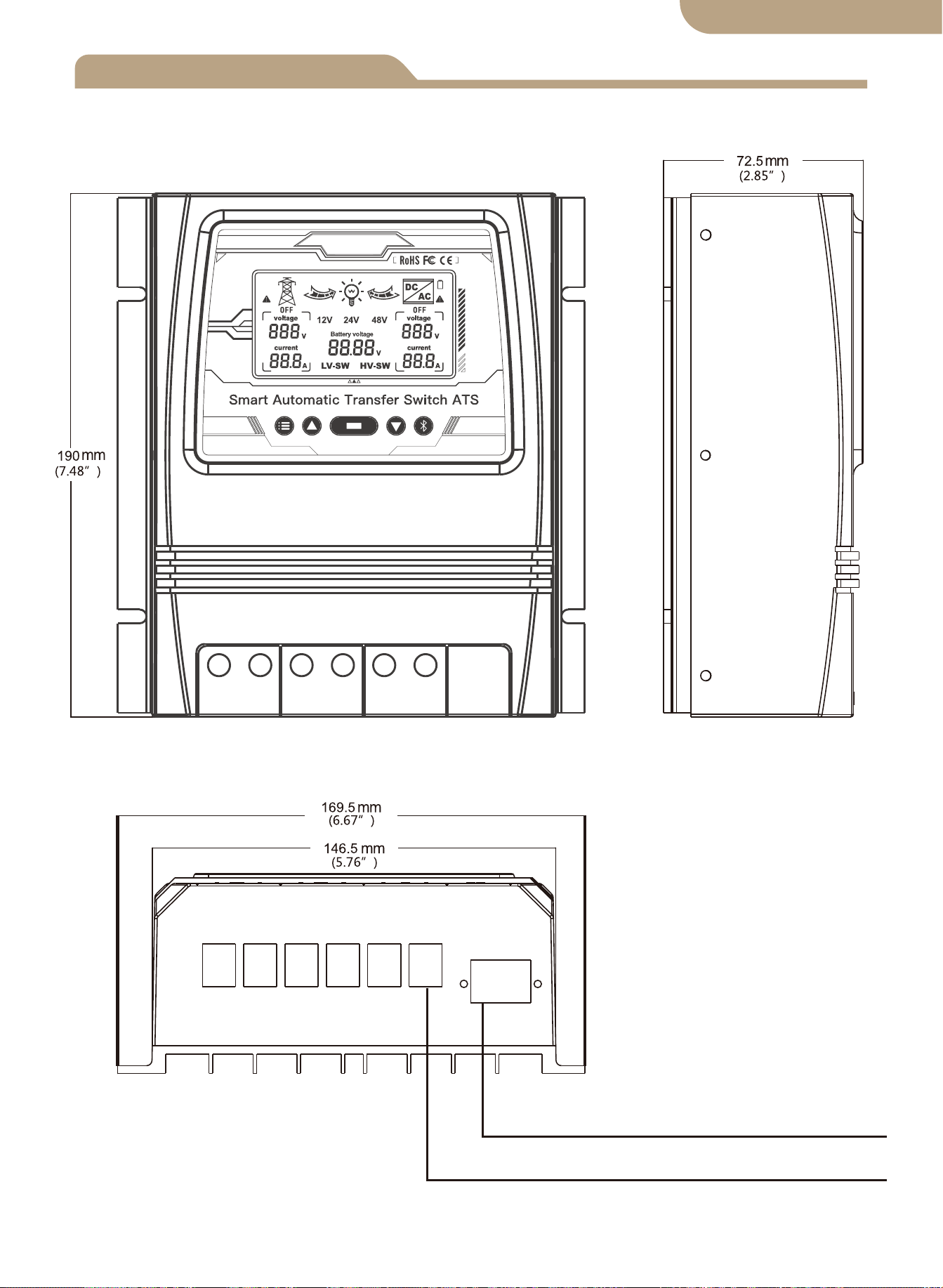
Product dimensions
Connection diagram
ATS Technical specifications
Installation notes
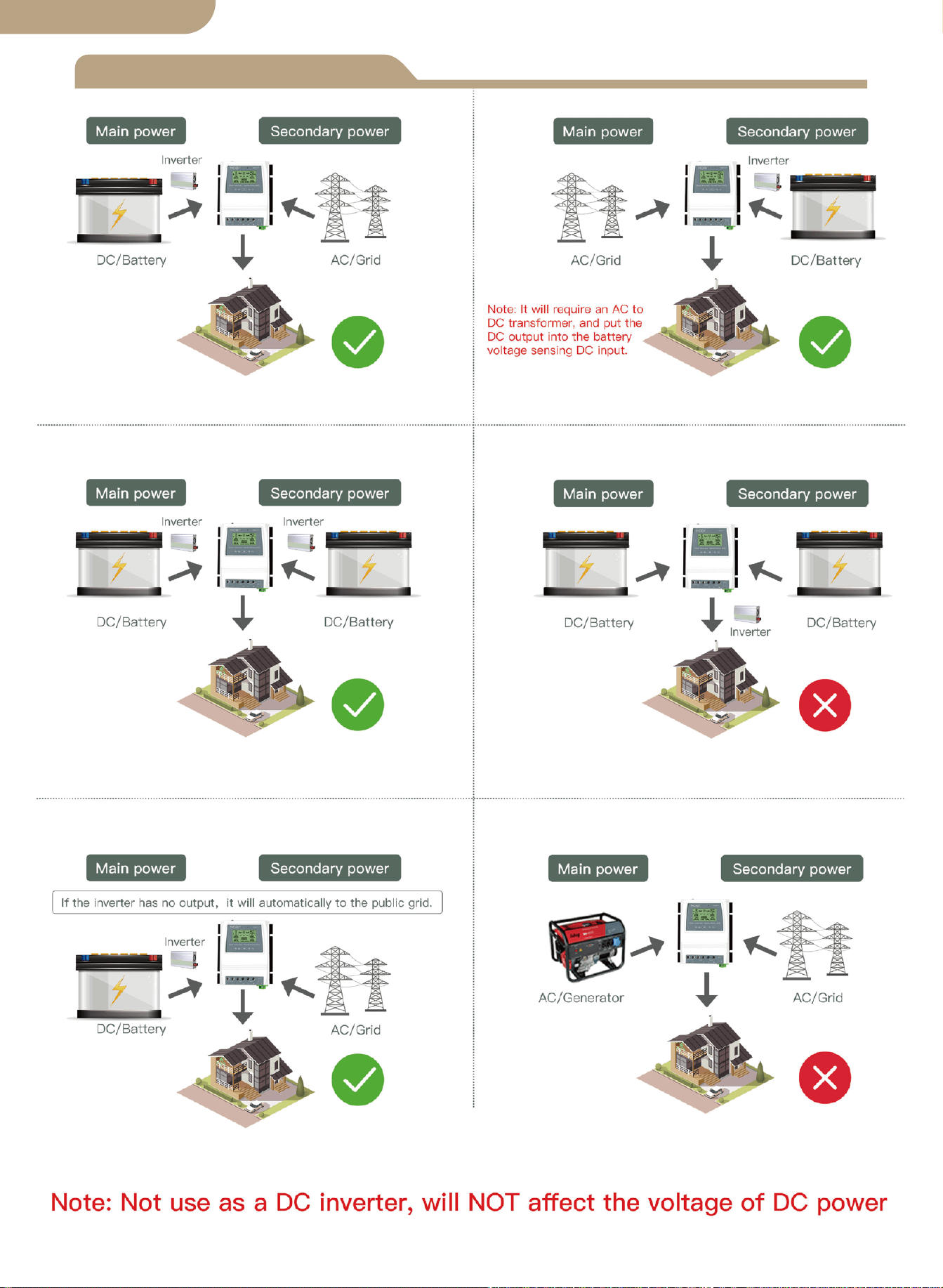
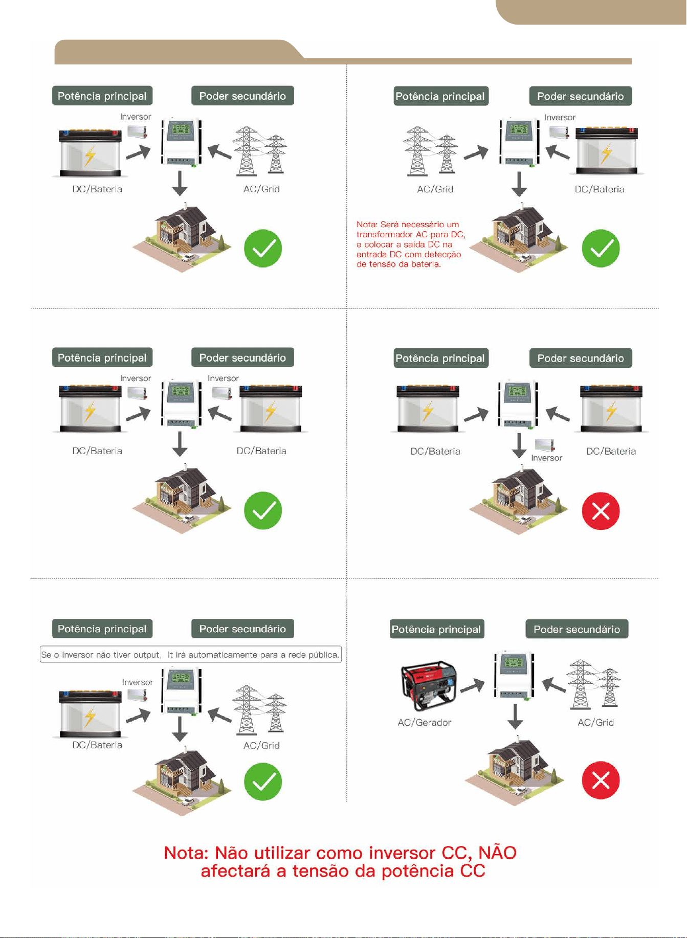
Application
Product introduction
Installation
Device pairing
Auto-select voltage range
Button functions
Display function selection
LCD backlight
12v System working specification
24v System working specification
48v System working specification
Add devices
Device reset
Model
Contents
Thank you very much for selecting our products.
Please review this manual carefully before installing and operating the Dual
Power Smart Automatic Transfer Switch.
Please note ALL safety recommendations.
01
02
03
03
04
04
04
04
05
LCD display
05
06
06
Error adjustment
06
07
07
07
07
08
08
08
Safety recomendations
12
Environmental protection
12
English version
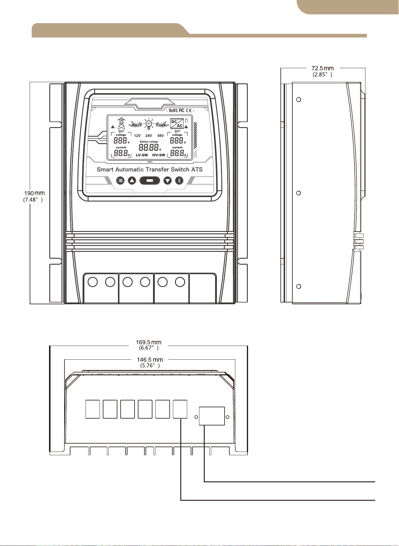
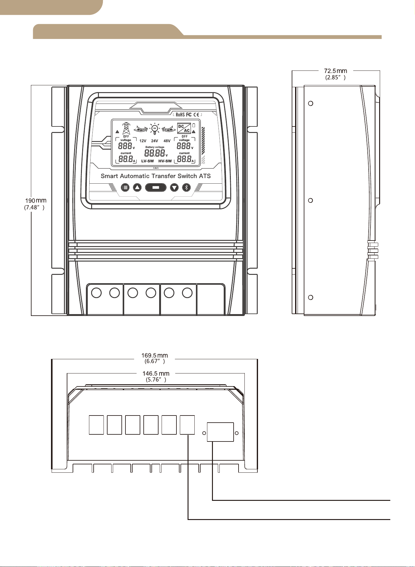
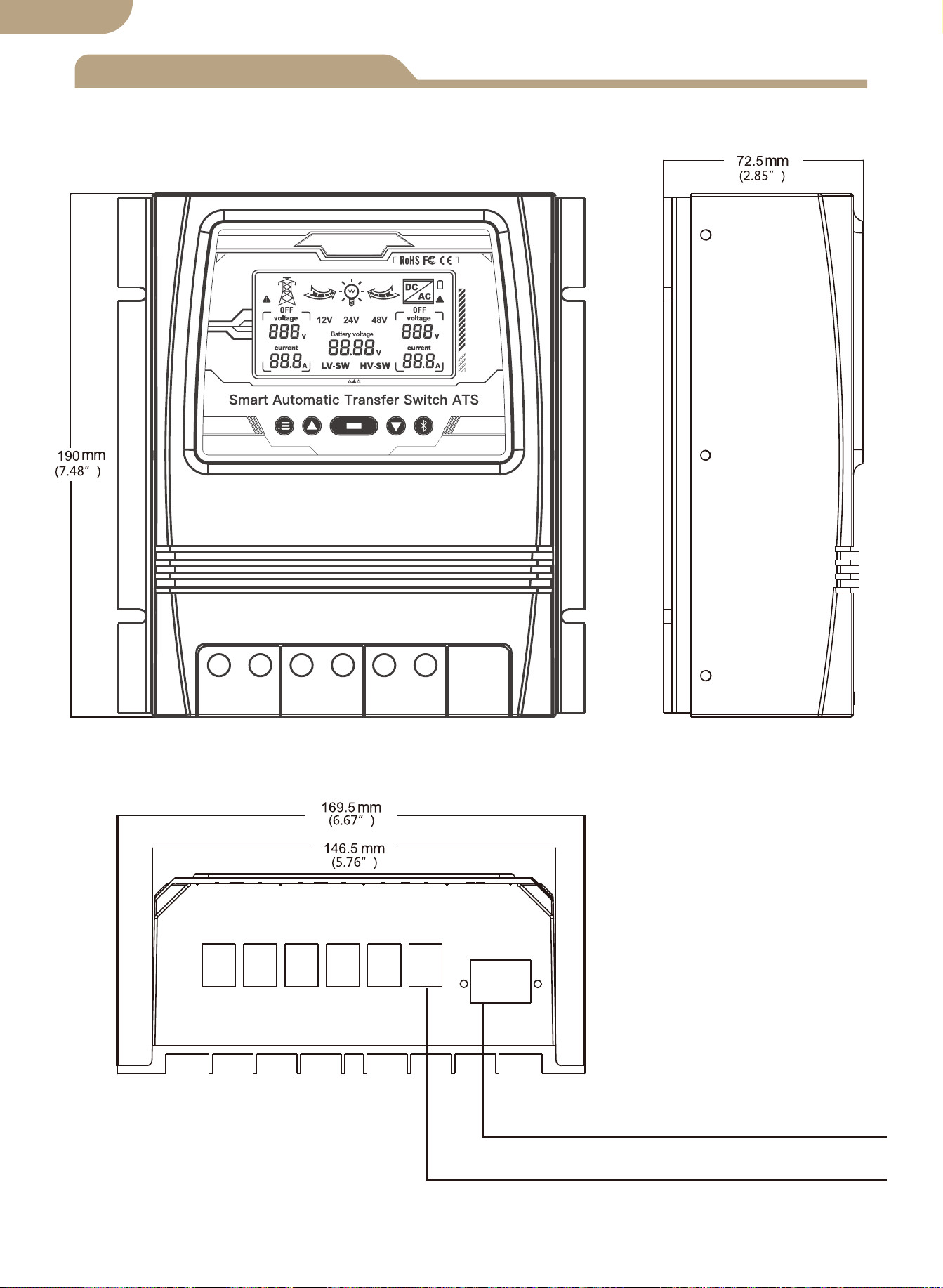
Product dimensions
Maximum Wire Gauge:AWG 14 (2.5mm²)
Maximum Wire Gauge:AWG 6 (16mm²)
01
English version
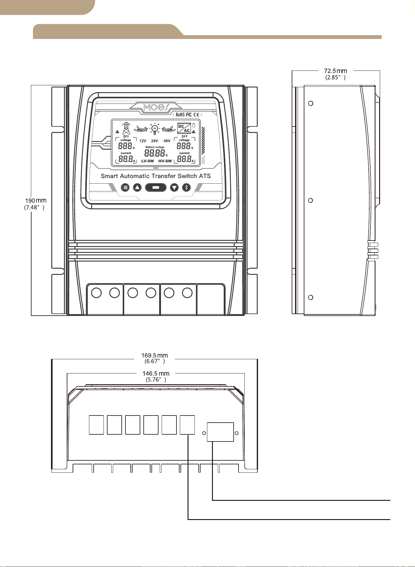
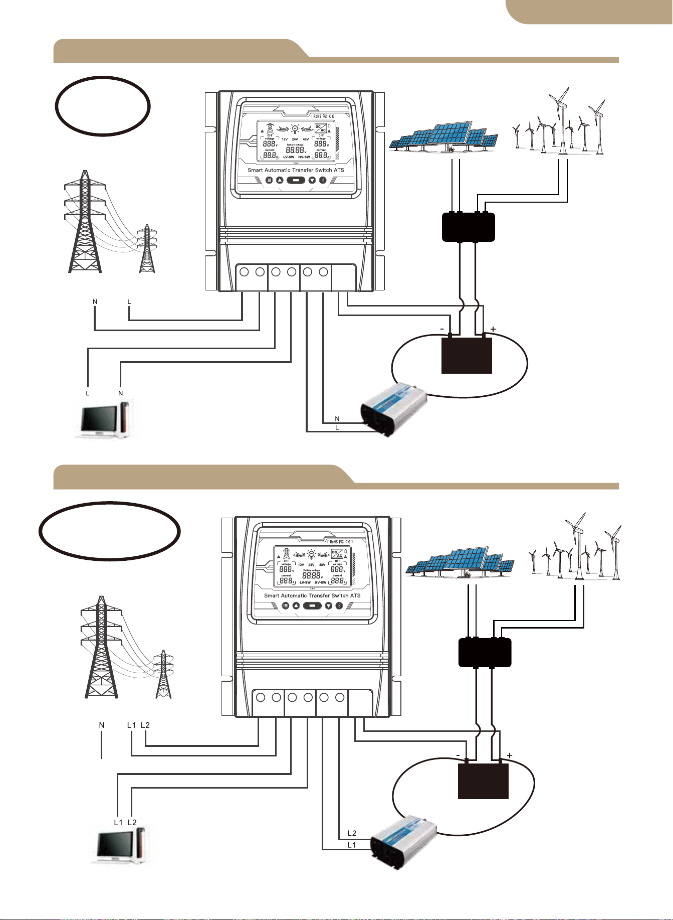
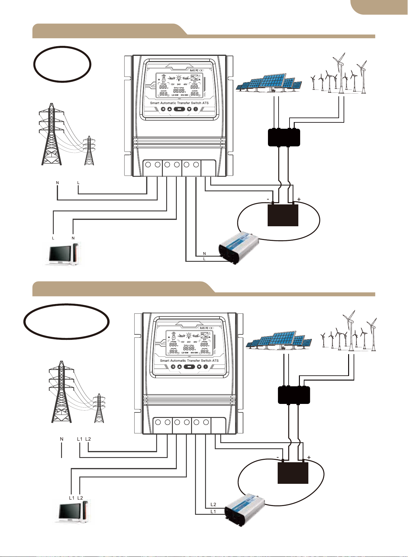
L+N Connection diagram
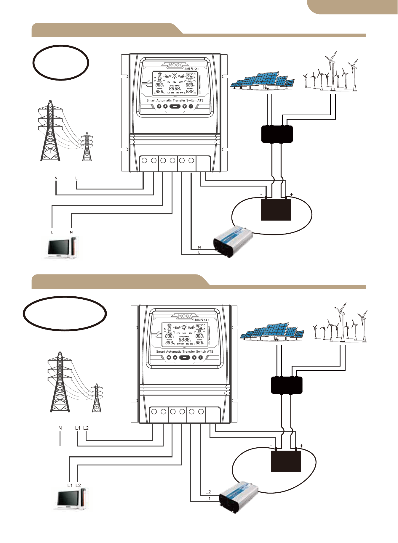
L1+L2+N Connection diagram
Solar&Wind Controller
Solar Panel
Wind Generator
Utility Power
Load
Inverter
Battery
Live+Neutral
Utility Power
Solar&Wind Controller
Solar Panel
Wind Generator
Load
Inverter
Battery
Live1+Live2+Neutral
02
Note:
The battery is a must for power supply.
Note:
The battery is a must for power supply.
English version
L N L N L N - +
L L L L L L - +
Installation Notes
03
English version

Technical Specifications
8kw (Utility Power 100-120V)
16kw (Utility Power 220-240V)
Auto Selection:
AC 100-120V or AC 220-240V
Inverter transfer time to utility power ≦ 10ms
Utility power transfer time to inverter ≦ 16ms
Model
Rated Power
Input Voltage
Output Voltage
Transfer time
LCD Display
System Voltage
Application
Product Size
N.W/PC
BAT-80A
Battery voltage; Power source: Utility
power or battery-inverter.
Auto Select: 12V or 24V or 48V
Default: 10.5v/21v/42v, adjustable
Default: 12.5v/25v/50v, adjustable
19*17*7.25cm(7.4”*6.7”*2.8”in)
1.32KG(2.9lbs)
Battery low voltage
transfer setpoints
Battery recovery
Setpoints
Off grid solar system;
Wind generator; Hydro generator
Auto Selection:
AC 100-120V or AC 220-240V
04
English version

Application
Product introduction
Installation
Auto-Select Voltage Range
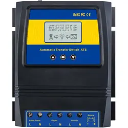
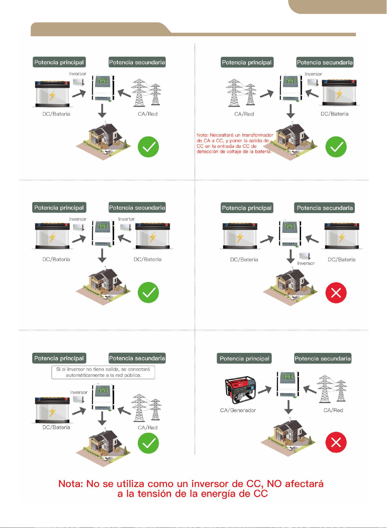
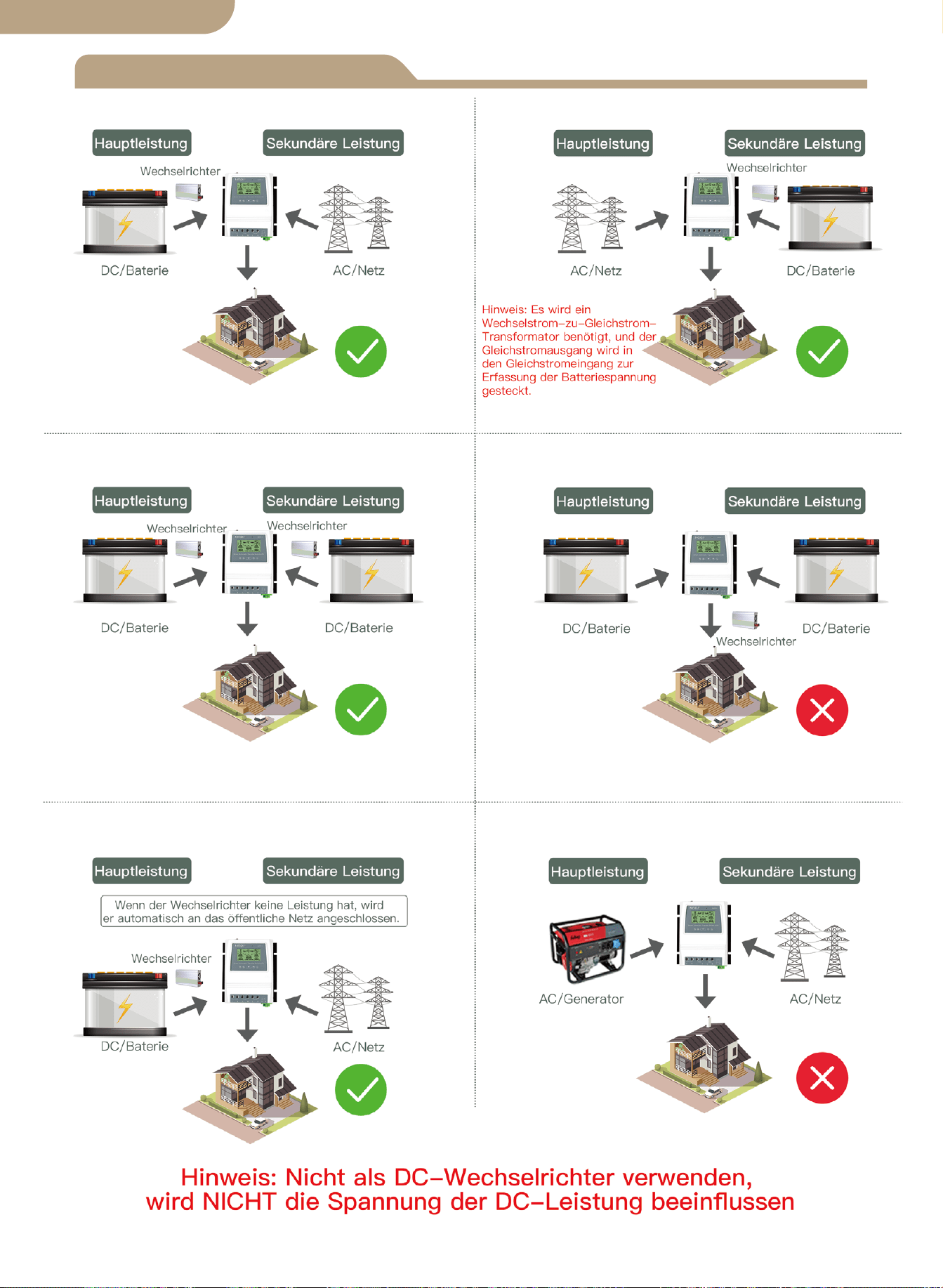
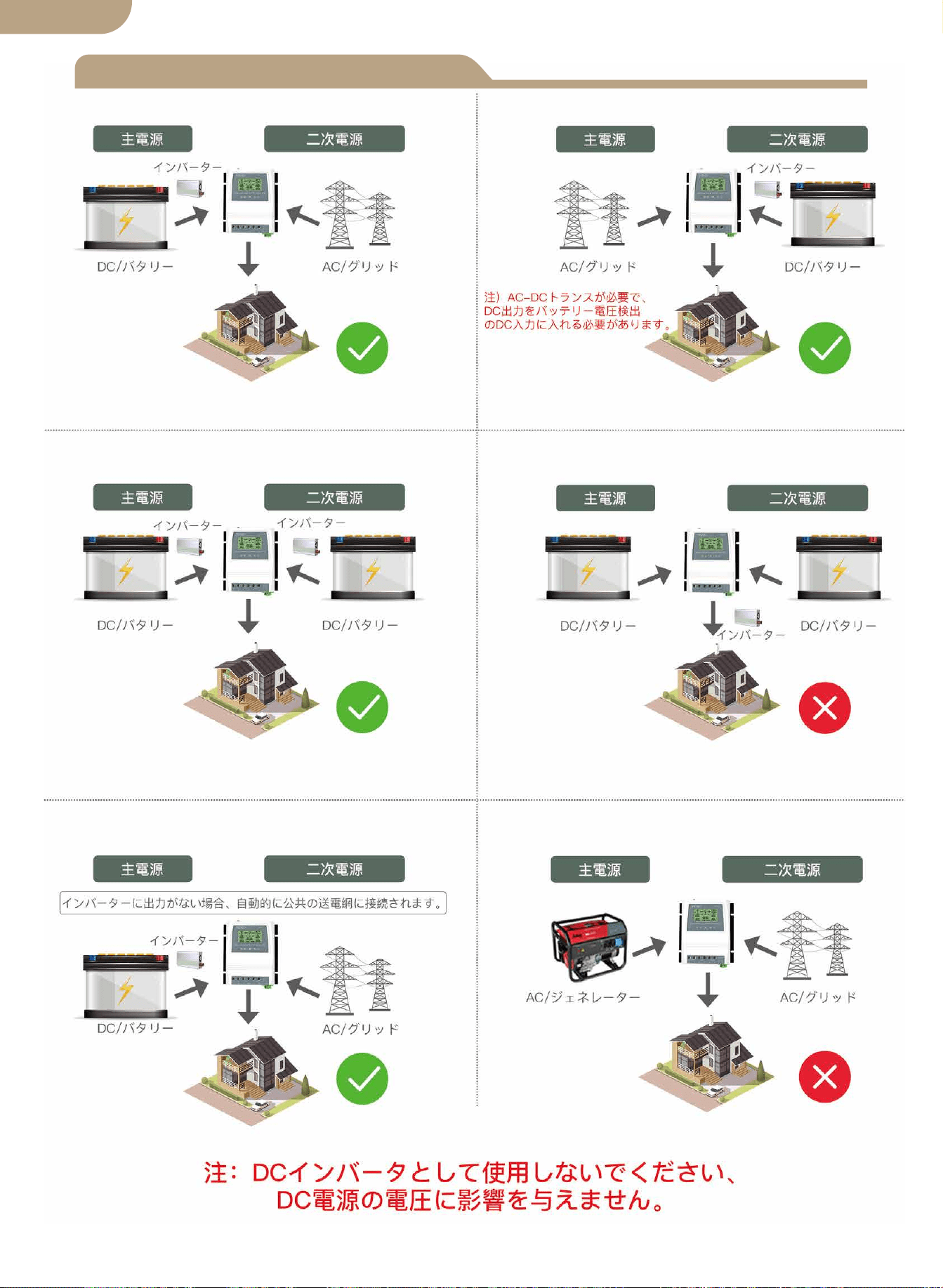
The ATS power transfer controller provides reliable operation of an inverter and AC
utility power in one compact device. The ATS switches automatically between the AC
utility power and the inverter, while protecting the inverter against external voltages.
The Dual Power Transfer Controller is used between an Off-Grid Power System and
the Public Utilty Power Supply. The ATS Controller connects separately to 1) Utility
Power 2) Inverter 3) Battery 4) Load. The User Interface allows for both Monitoring of
the ATS Operating State and Adjusting Voltage Setpoints. The Master ON/OFF Switch
is located at the top of the controller for easy access.
The design of your off-grid system and installation of this transfer switch should
only be performed by qualified end users, electricians or technicians authorized and
licensed where required by local codes.
Before installation of this device, please review this manual in its entirety before
beginning.
Install / mount the ATS controller to a clean, and dry surface, and in a suitable
location that will allow free air circulation around the ATS at all times. Insure all
cables are of adequate length to allow for proper strain relief at the ATS connec-
tion block.
Insure all safety protocols are followed. Check all ac power supplies are off and
secured with a safety lock-out tag system to prevent inadvertent power actuation.
All power connection cables must meet minimum wire gauge recommendations set
by standard electrical requirements and your local codes.
Verify all connections are connected and tightened properly! Loose electrical con-
nections will overheat and can damage the ATS and can cause fires.
Do not connect the neutral connector on the user side to ground connection or to a
protective ground connector, as the user outlets have no protective multiple
grounding.
Note! Do not connect the “pe” grounding wire (protective earth) to the neutral
connector.
After insuring the above steps are complied with and you have verified all the con-
nections are properly terminated, proceed with the final connections to the utility
power, inverter, battery, and load (s).
Turn on the master switch located at the top of the ATS.
Perform voltage & ammeter checks on your newly installed system to verify your
ATS is operating within the specified operating parameters.
1.
2.
3.
4.
5.
6.
7.
8.
9.
10.
05
12V system detection voltage range 9V-17V
24V system detection voltage range 18V-30V
48V system detection voltage range 30V-60V
English version
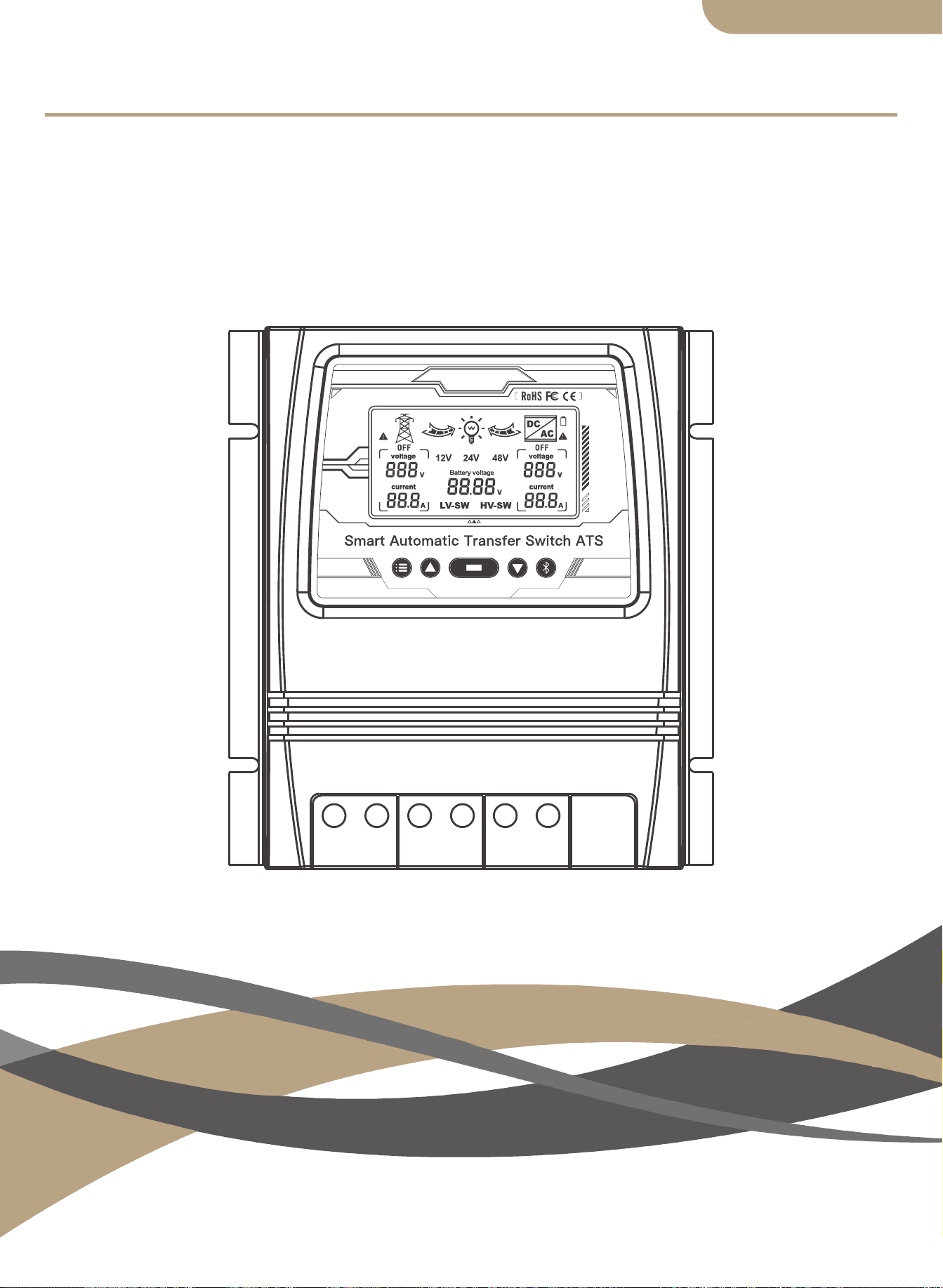
LCD Display
Model
06
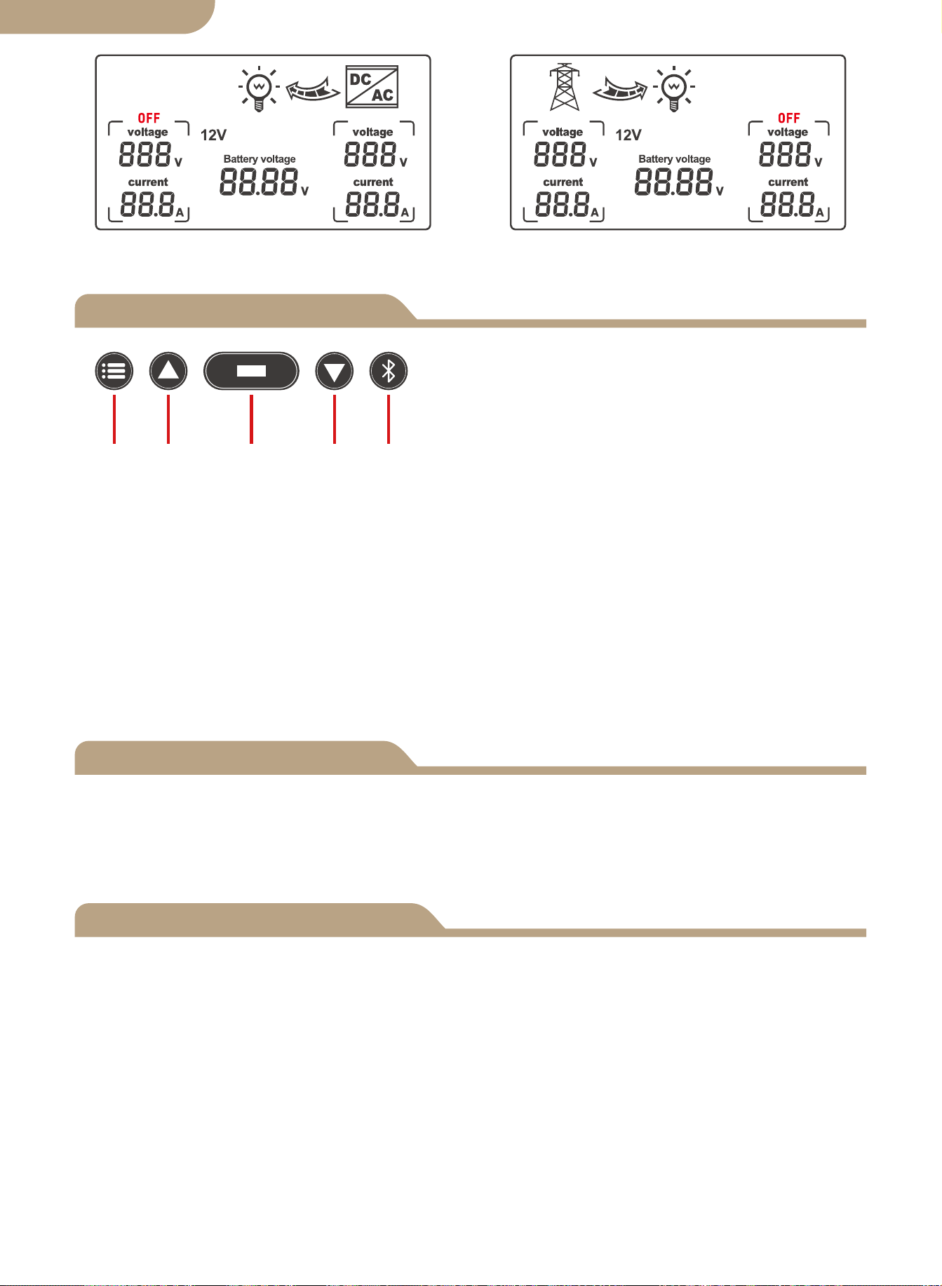
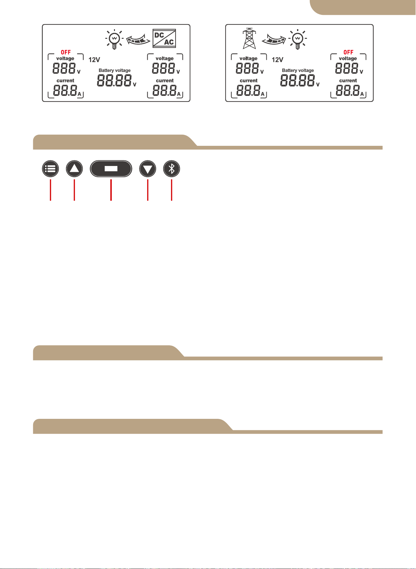
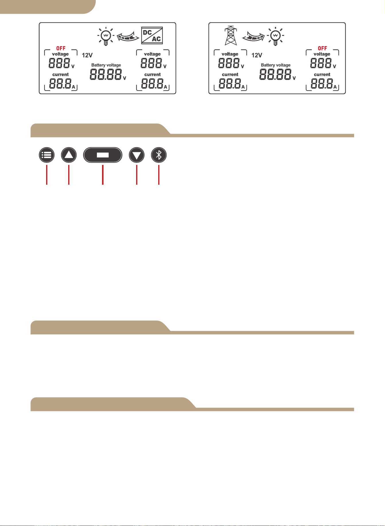
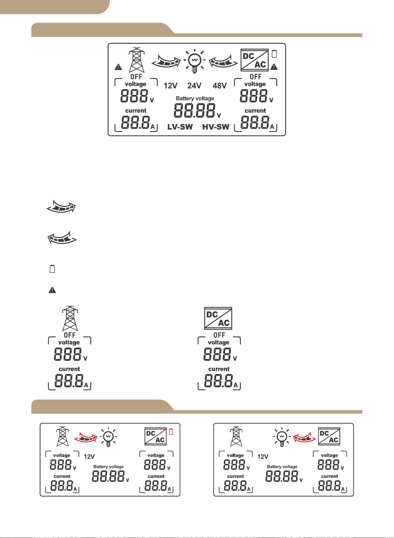
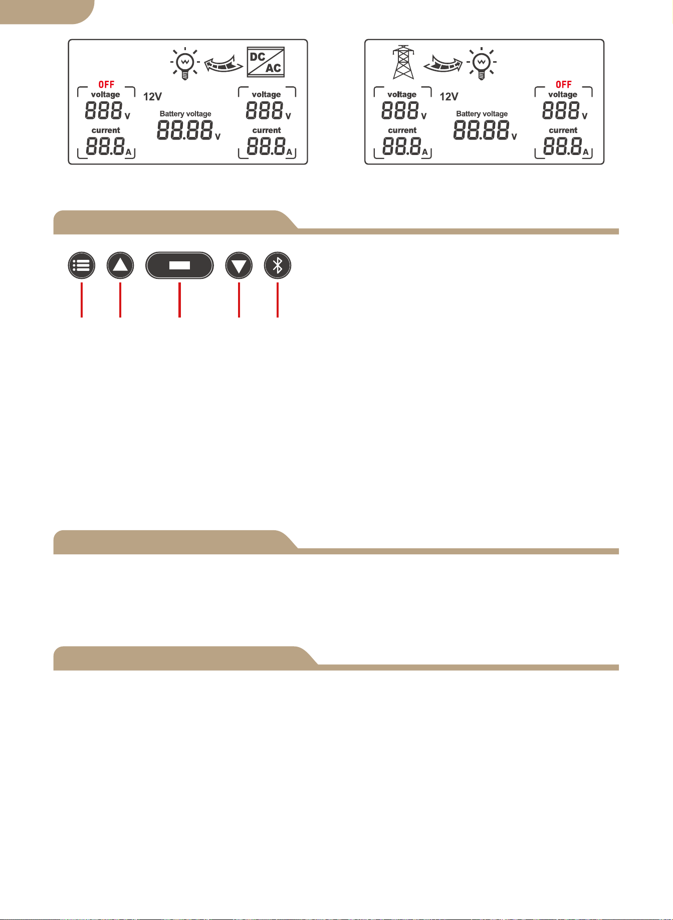
Automatic mode switching grid status Automatic mode switching inverter
state
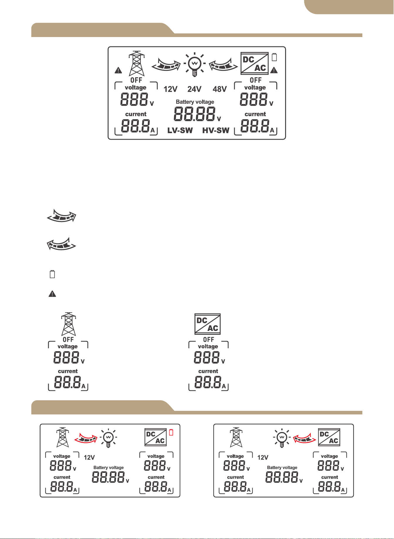
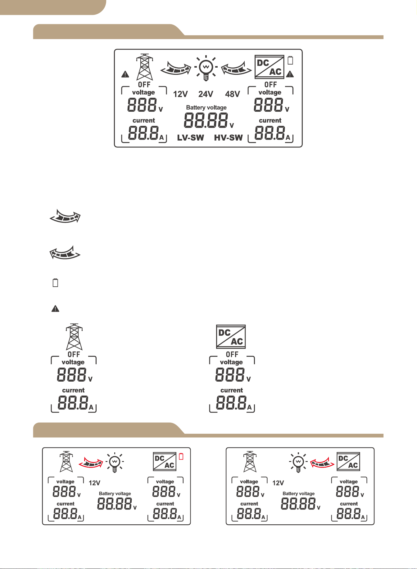
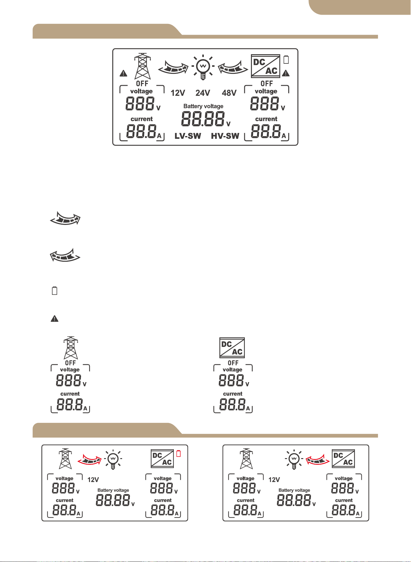
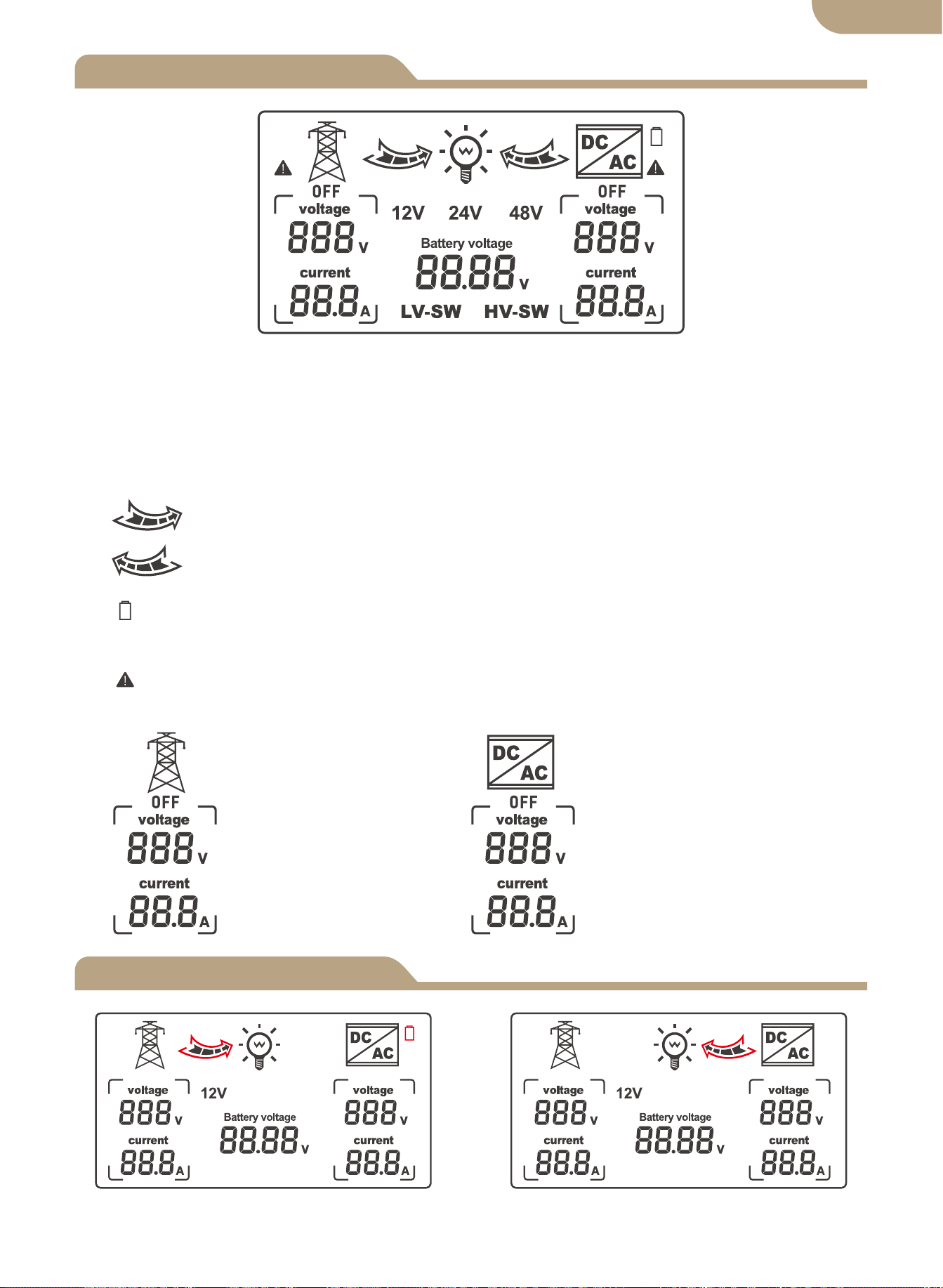
1. When LV-SW is displayed, it is the function interface for setting battery low voltage
switching voltage.
2. When HV-SW is displayed, it is the function interface for setting the battery low
voltage recovery voltage.
3. 12V, 24V, 48V is the corresponding display voltages after respectively indentified by
the system.
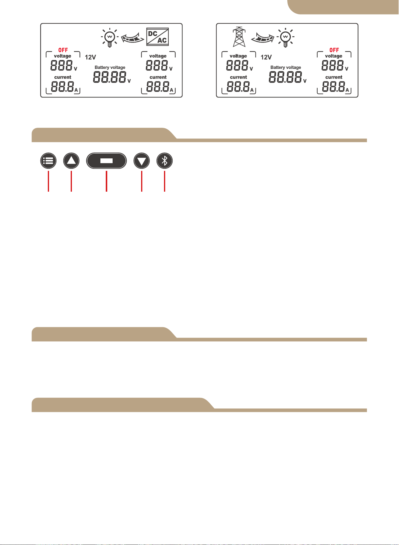
4. The right arrow shows switching to the public power,and the internal grid
flashes to display the current output state,no display when no current output.
5. The left arrow shows switching to the inverter, and the internal grid flashes
to display the current output state, no display when no current output.
6. The battery icon displays the low voltage switching state with flashing perfor-
mance.
7. Displayed with flashing performance when there is the failure of non-voltage AC
current.
8.
Corresponding grid
display on AC voltage
and current.
Corresponding inverter
display on AC voltage
and current.
English version
Display Function Selection
Error Adjustment
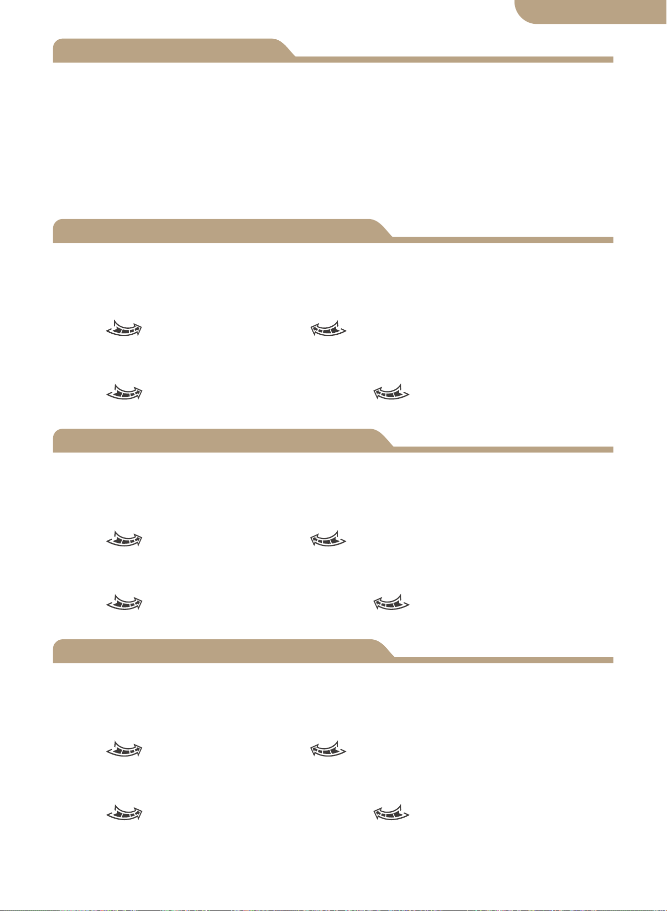
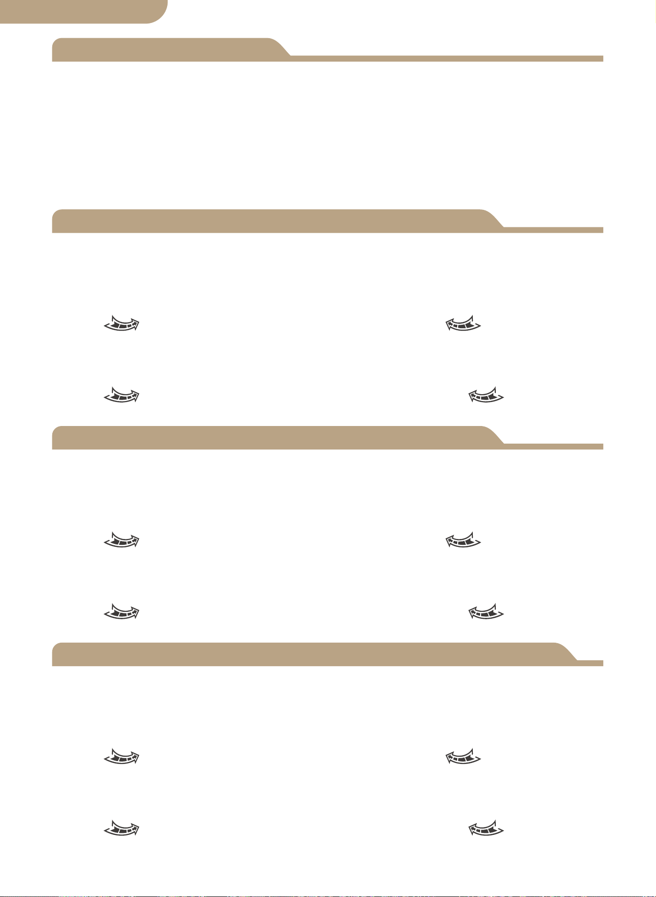
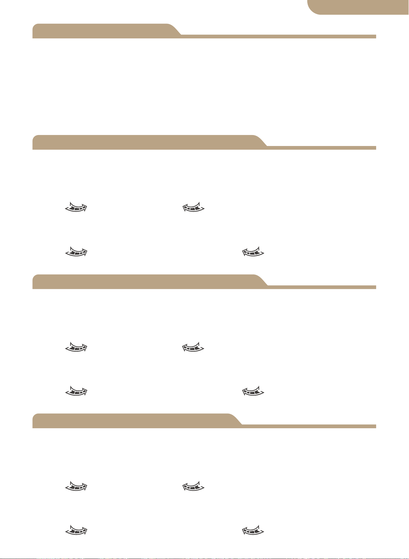
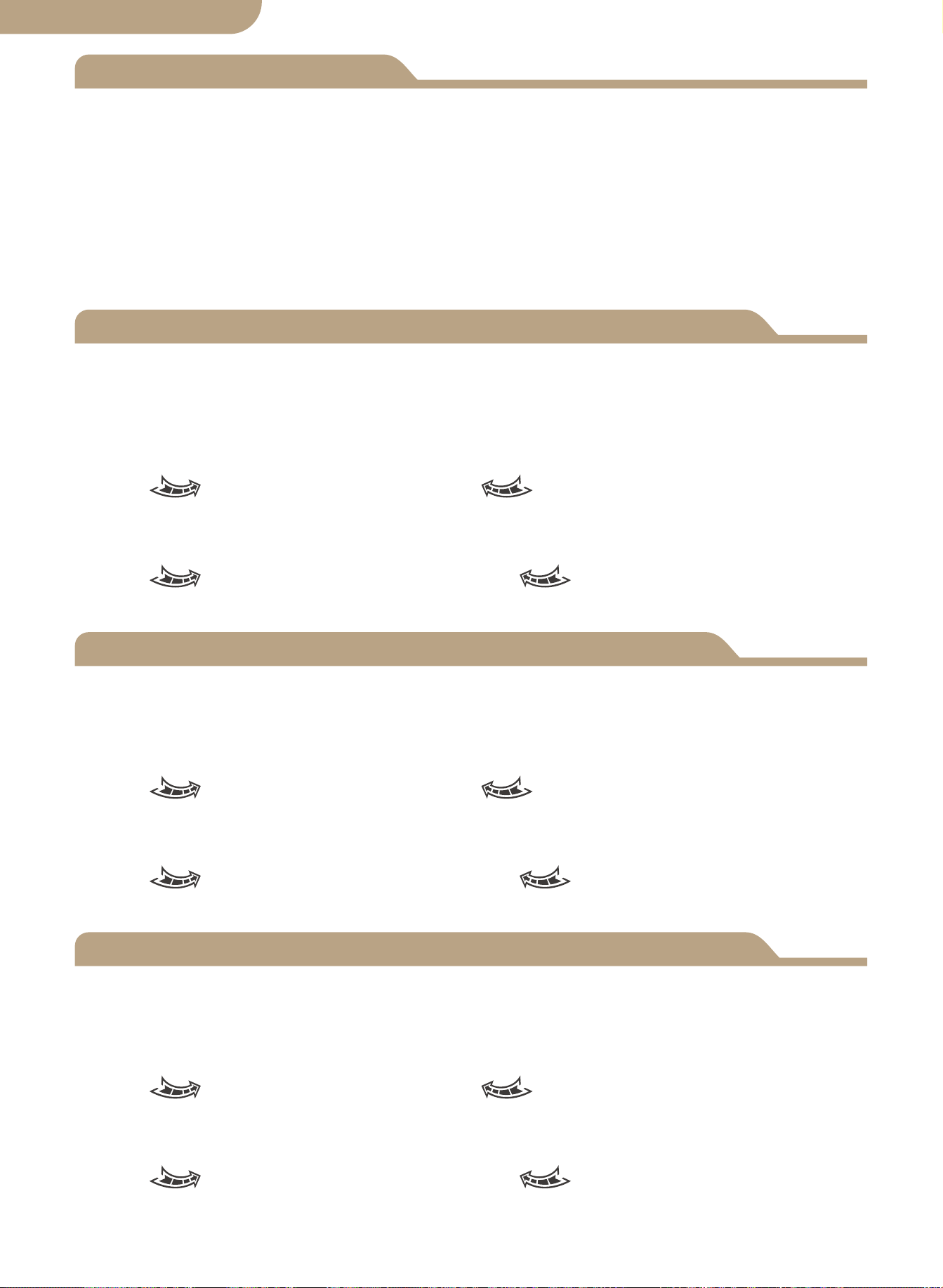
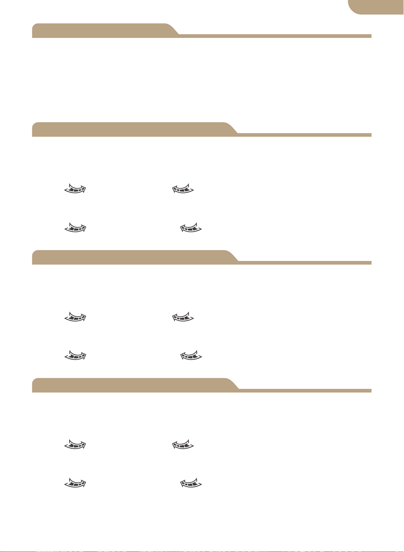
Front Panel Key Buttons:
a. Mode button
b. Plus button
c. Function button
d. Minus button
e. APP Configuratin Button
Button Functions
a b c d e
a.Mode button: switch between automatic mode, grid power supply mode, and inverter
b.The plus button is only valid for voltage setting (0.1V per trigger).
c.
Function button: set the LV-SW voltage, HV-SW voltage and battery voltage, which
d.The minus button is only valid for voltage setting (0.1V per trigger).
e.APP Configuration Button: press and hold for 6s to enter the network distribution
If any error voltage value occurs, press and hold the add button and the minus button
at the same time for 3 seconds to release the 0.0V voltage flicker. Press the add or
minus button to modify the detection error voltage value. Press and hold the function
button for 3 seconds after modification to save the modified value.
① When function setting display the BAT-V interface, (system default display) the LCD
digital display system is real-time tracking battery voltage.
② When function setting display the LV-SW interface, the LED digital display
low-voltage switch voltage(default value), then press the button to increase or to
modify the default value, pressing and holding the function button for 3 seconds to
save and modify the value, after the LCD changing to the default BAT-V interface.
③ When function setting display the HV-SW interface, the LED digital display
low-voltage recovery voltage (default value), then press the button to increase or to
modify the default value, long pressing the function button for 3 seconds to save the
modified value, after the LCD changing to the default BAT-V interface.
07
Inverter power supply status Utility power status
English version
power supply mode.
state, the blue indicator flashes.
will be displayed in a cycle when the button is presse .The battery voltage is dis-
played by default when the device is power on; When there is no trigger signal on the
setting interface, the default display interface will be restored after 10 seconds.
The LCD Display Backlight will Automatically Turn OFF if NO Button Activity is sensed
after 60 Seconds.
Pressing Any Button will again illuminate the LCD Display for 60 Seconds.
Please Note! The LCD Panel will NOT Display / Illuminate or Function until the ATS is
Properly Connected to the Required DC Power Battery Source Circuit of Minimum
Detected Voltage.
This is a Safety Function of the ATS.
-------------------------------------------------------------------
LCD Backlight
12V System Working Specification
24V System Working Specification
48V System Working Specification
08
a. Battery level-LCD display.
b. Detection cut off and recovery point voltage
When it is detected that the battery voltage is lower than 10.5V for 2 seconds (system
default 11V), it is the low-voltage switching voltage, and the switching action is:
LCD- Right arrow flashes, LCD- Left arrow display turned off, battery
icon flashes.
When detecting the battery voltage rise 12.5V for 2 seconds (system default 13.5V), it
is the low-voltage recovery voltage, and the switching action is:
LCD- Right arrow display turned off, LCD- Left arrow shows flashing,
battery icon flashes off.
a. Battery level-LCD display.
b. Detection cut off and recovery point voltage
When it is detected that the battery voltage is lower than 21V for 2 seconds (system
default 22V), it is the low-voltage switching voltage, and the switching action is:
LCD- Right arrow flashes, LCD- Left arrow display turned off, battery
icon flashes.
When detecting the battery voltage rise 25V for 2 seconds(system default 27V), it is
the low-voltage recovery voltage, and the switching action is:
LCD- Right arrow display turned off, LCD- Left arrow shows flashing,
battery icon flashes off.
a. Battery level-LCD display.
b. Detection cut off and recovery point voltage
When it is detected that the battery voltage is lower than 42V for 2 seconds (system
default 44V), it is the low-voltage switching voltage, and the switching action is:
LCD- Right arrow flashes, LCD- Left arrow display turned off, battery
icon flashes.
When detecting the battery voltage rise 50V for 2 seconds(system default 54V), it is
the low-voltage recovery voltage, and the switching action is:
LCD- Right arrow display turned off, LCD- Left arrow shows flashing,
battery icon flashes off.
English version
Add Devices
Device Reset
② Registration or Log in.
• Download “MOES” Application.
• Enter the Register/Login interface; tap “Register” to create an account by entering
your phone number to get verification code and “Set password”. Choose “Log in” if
you already have a MOES account.
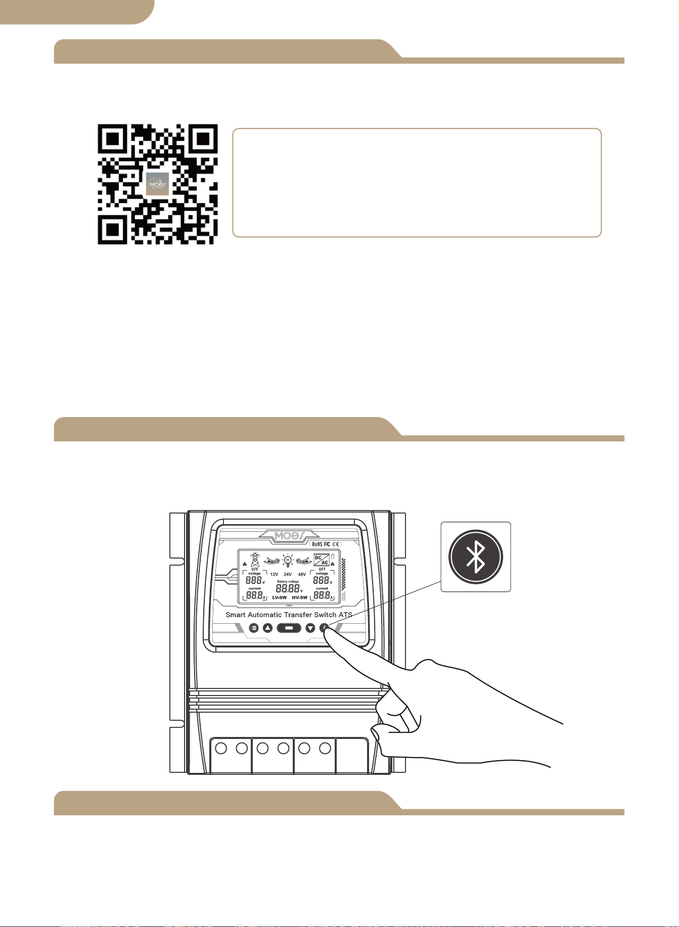
③ Configure the APP to the switch.
• Preparation: Ensure the switch has been connected with electricity; ensure your
phone has been connected to Wi-Fi and is able to connect to the Internet.
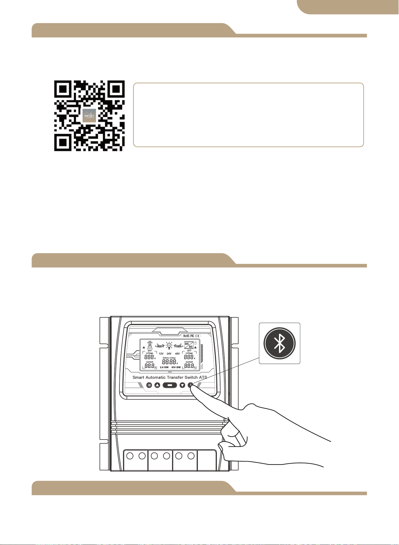
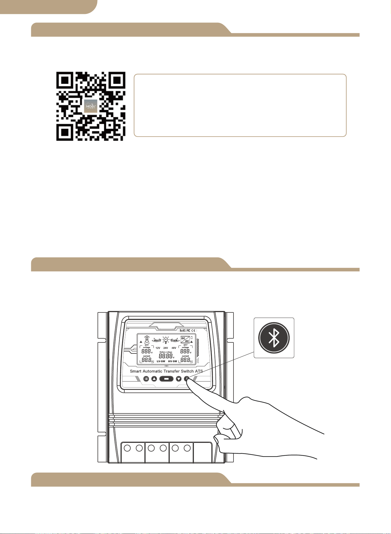
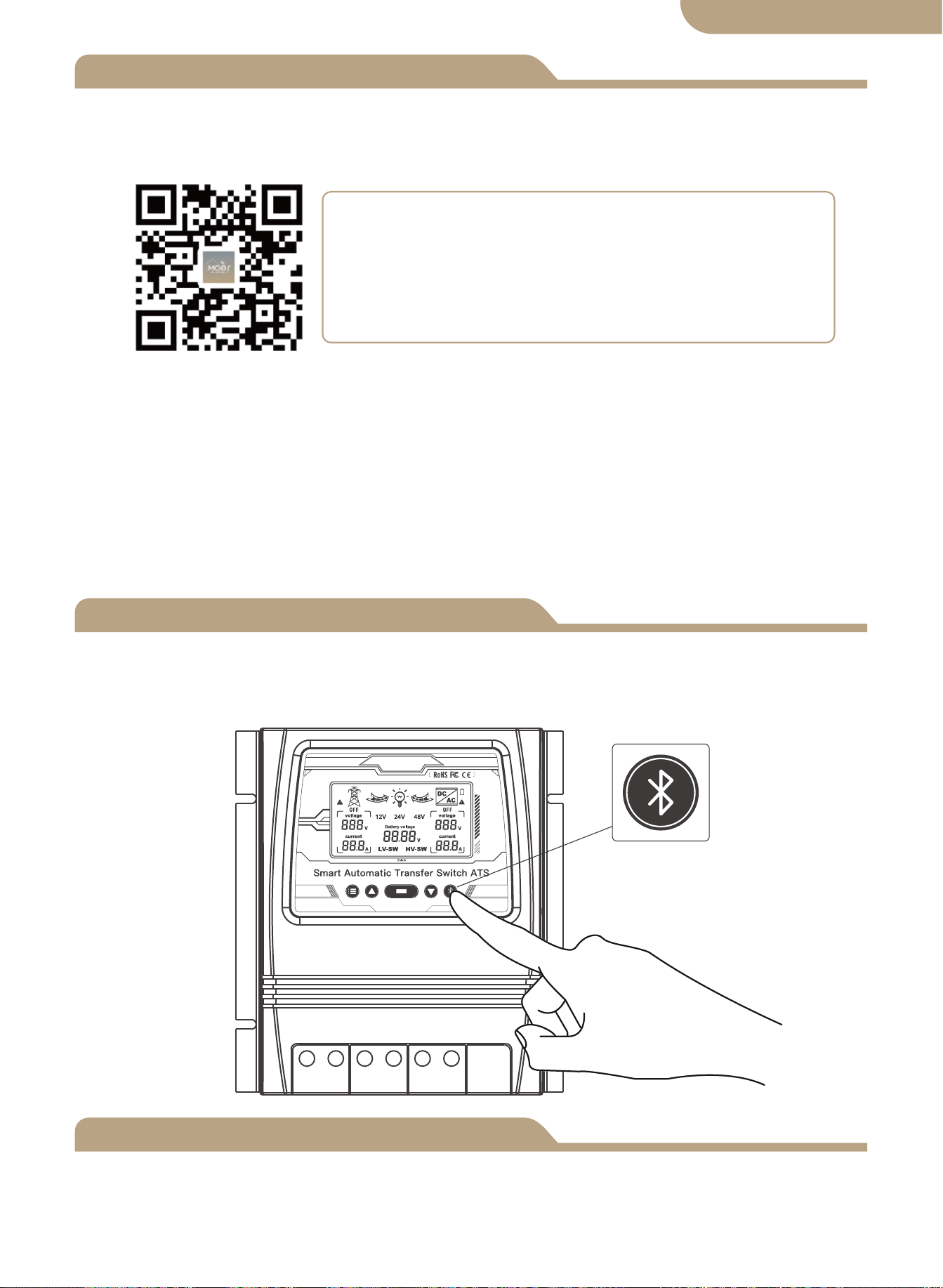
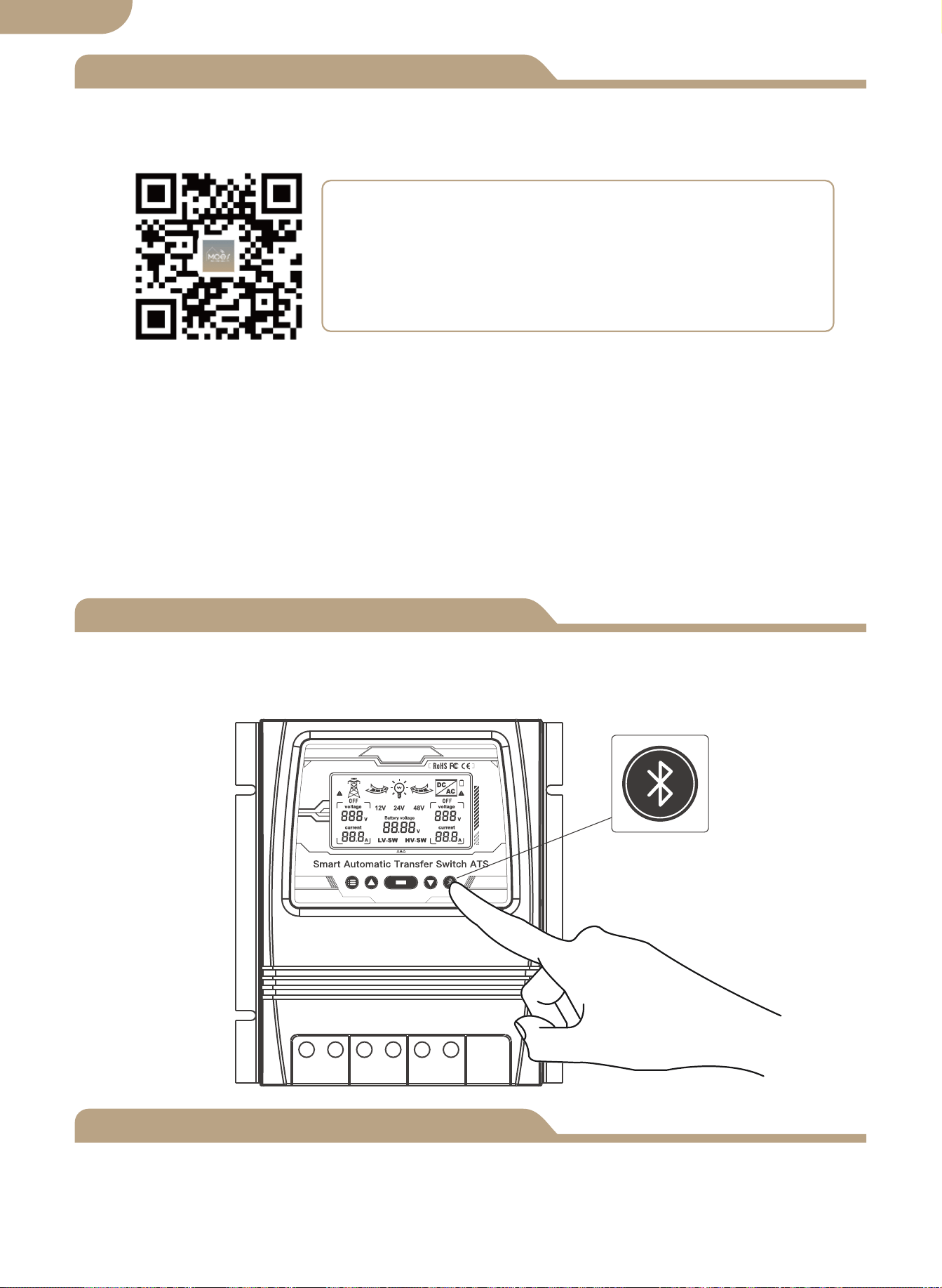
Press and hold the button for about 6 seconds, the blue indicator on the switch flashes
fast after 3 seconds. Re-pair is successful.
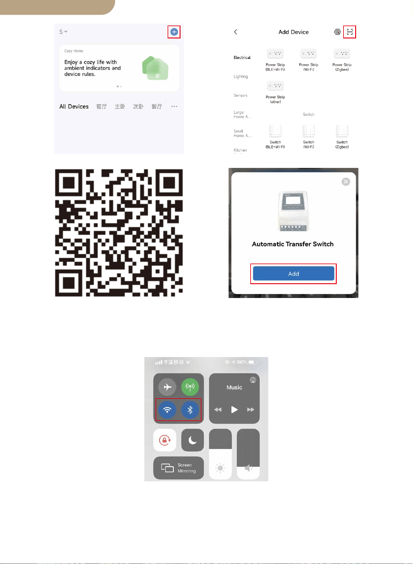
Device Pairing
Method one:
Scan the QR code to configure the network guide.
09
English version
① Download MOES App on App store or scan the QR code
MOES App is upgraded as much more compatibility than
Tuya Smart/Smart Life App, functional well for scene
controlled by Siri, widget and scene recommendations as
the fully new customized service.
(
Note: Tuya Smart/Smart Life App still works, but MOES
App is highly recommended)

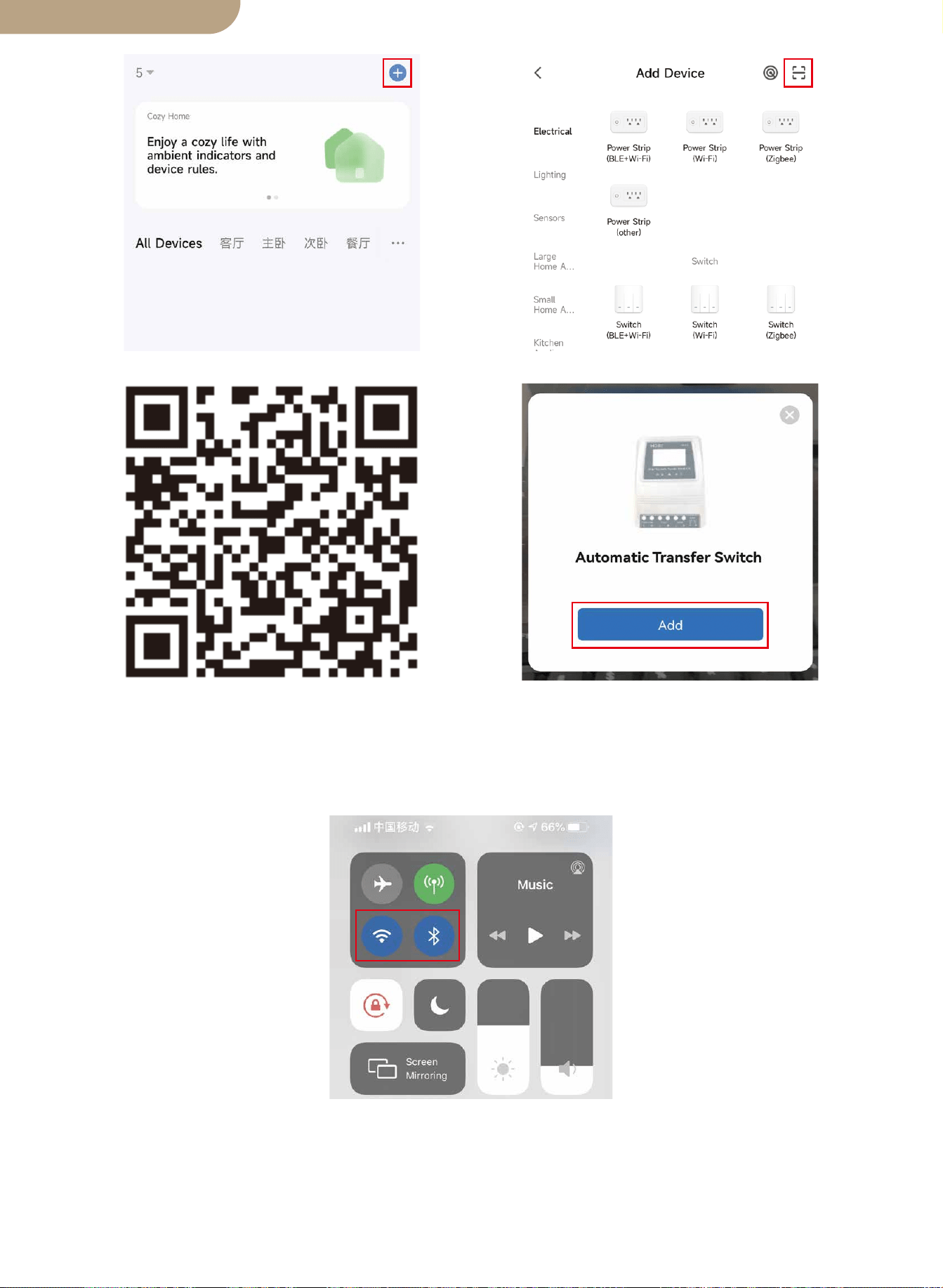
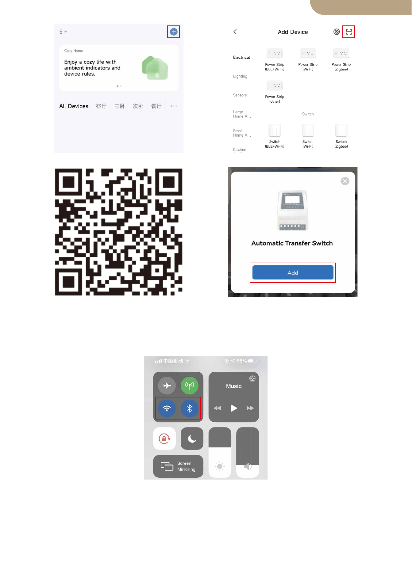
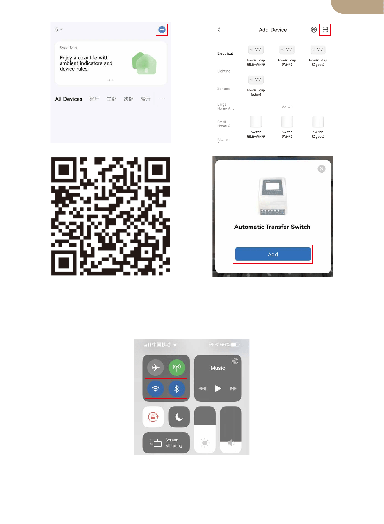
Method two:
1.Make sure the device has been reset.
⑴ ⑵
Scan the QR code Please connect the device accord-
ing to the configuration process.
10
English version
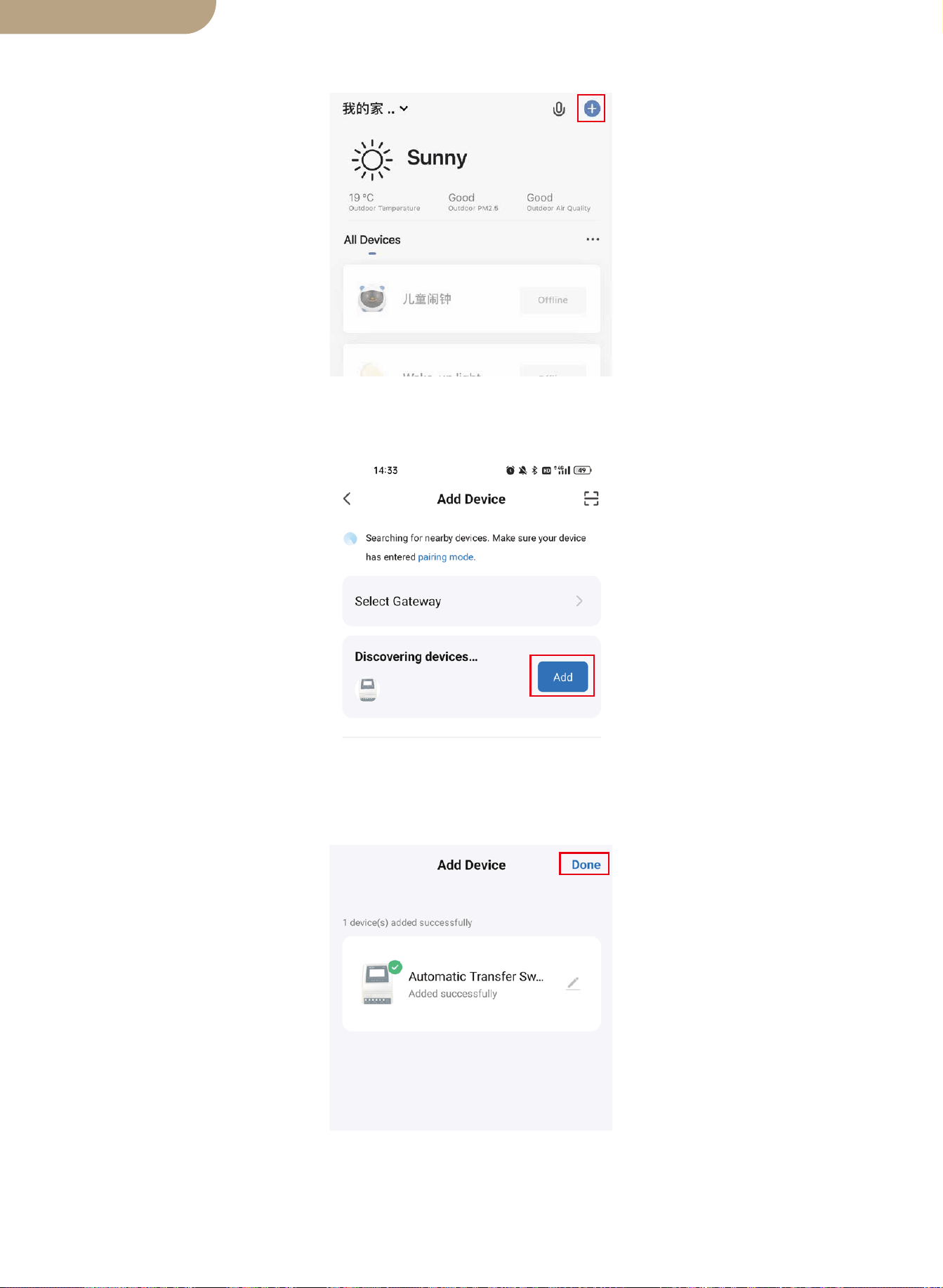
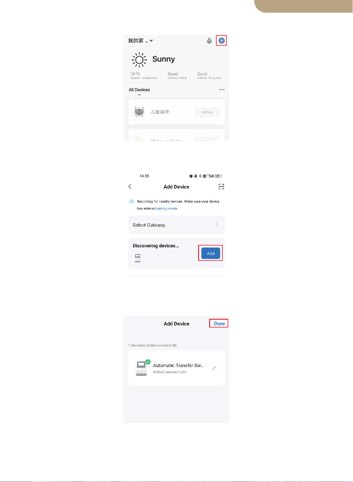
2.Make sure your phone is connected to Wi-Fi and Bluetooth.
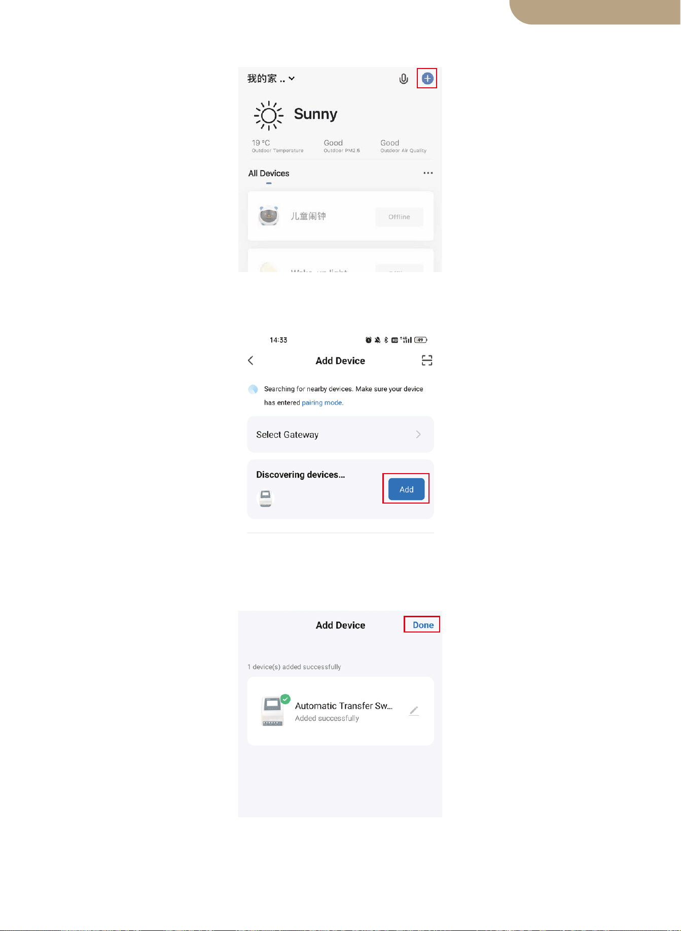
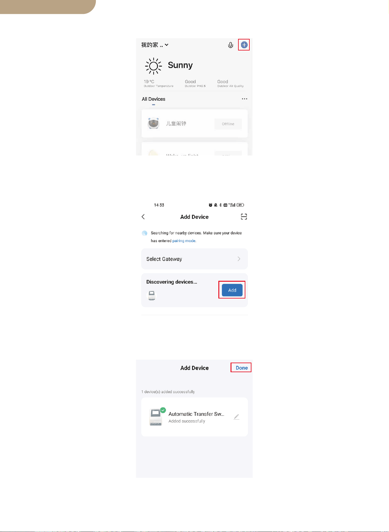
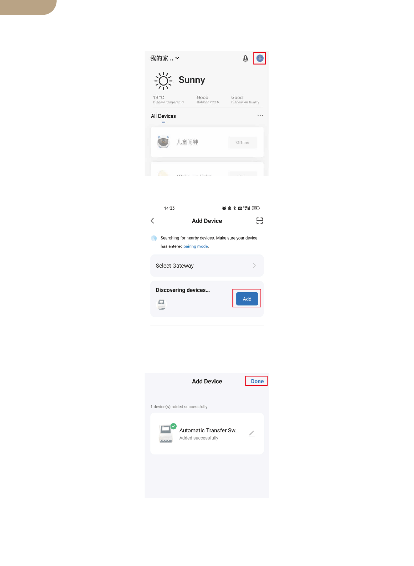
3.Open Smart Life/Tuya App and Click “+”, then the prompt page will automatically
show on the screen. Click “Go to add”.
4.Add the device successfully, you can edit the name of the device to enter the device
page by click “Done”.
11
English version
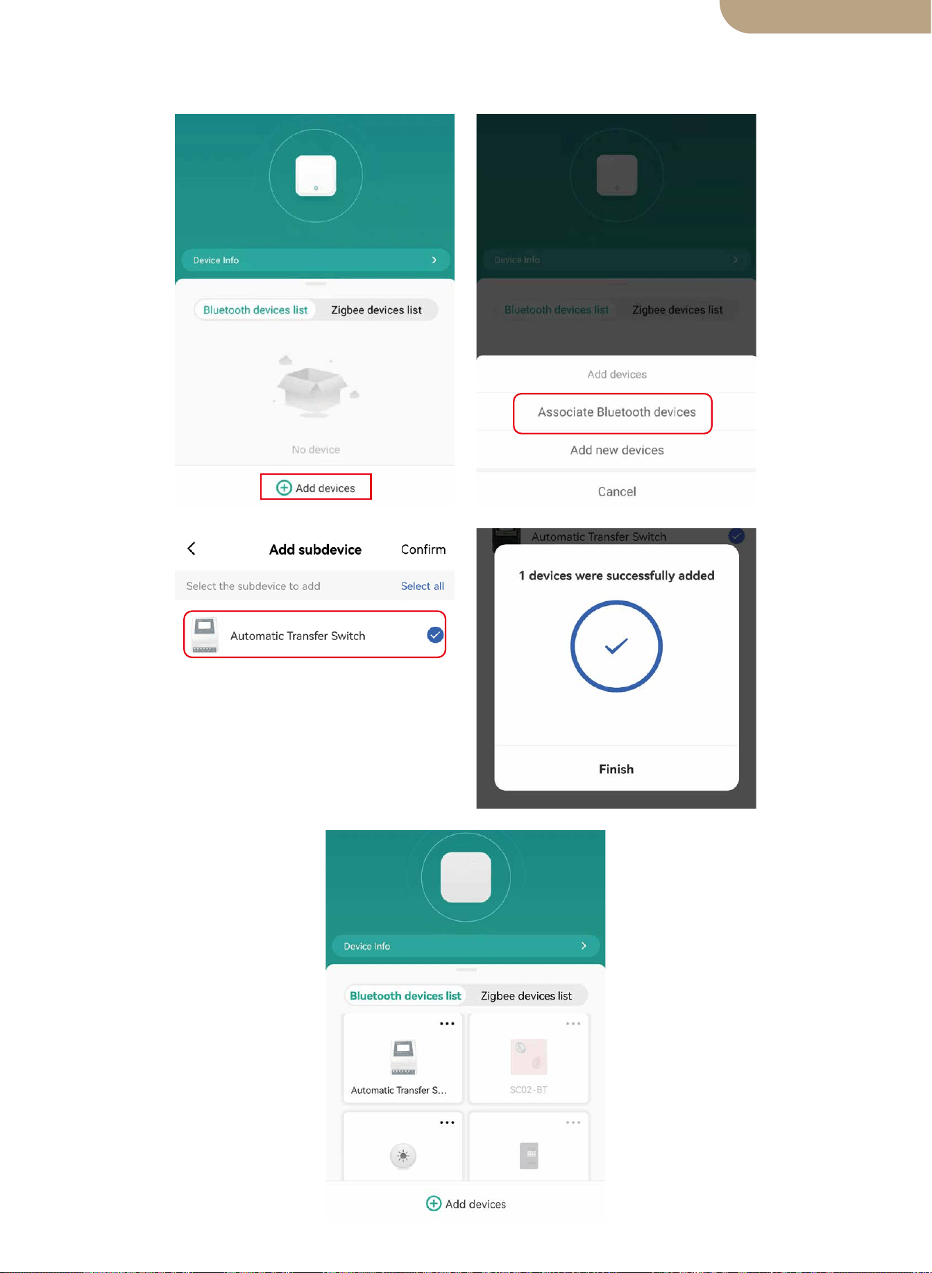
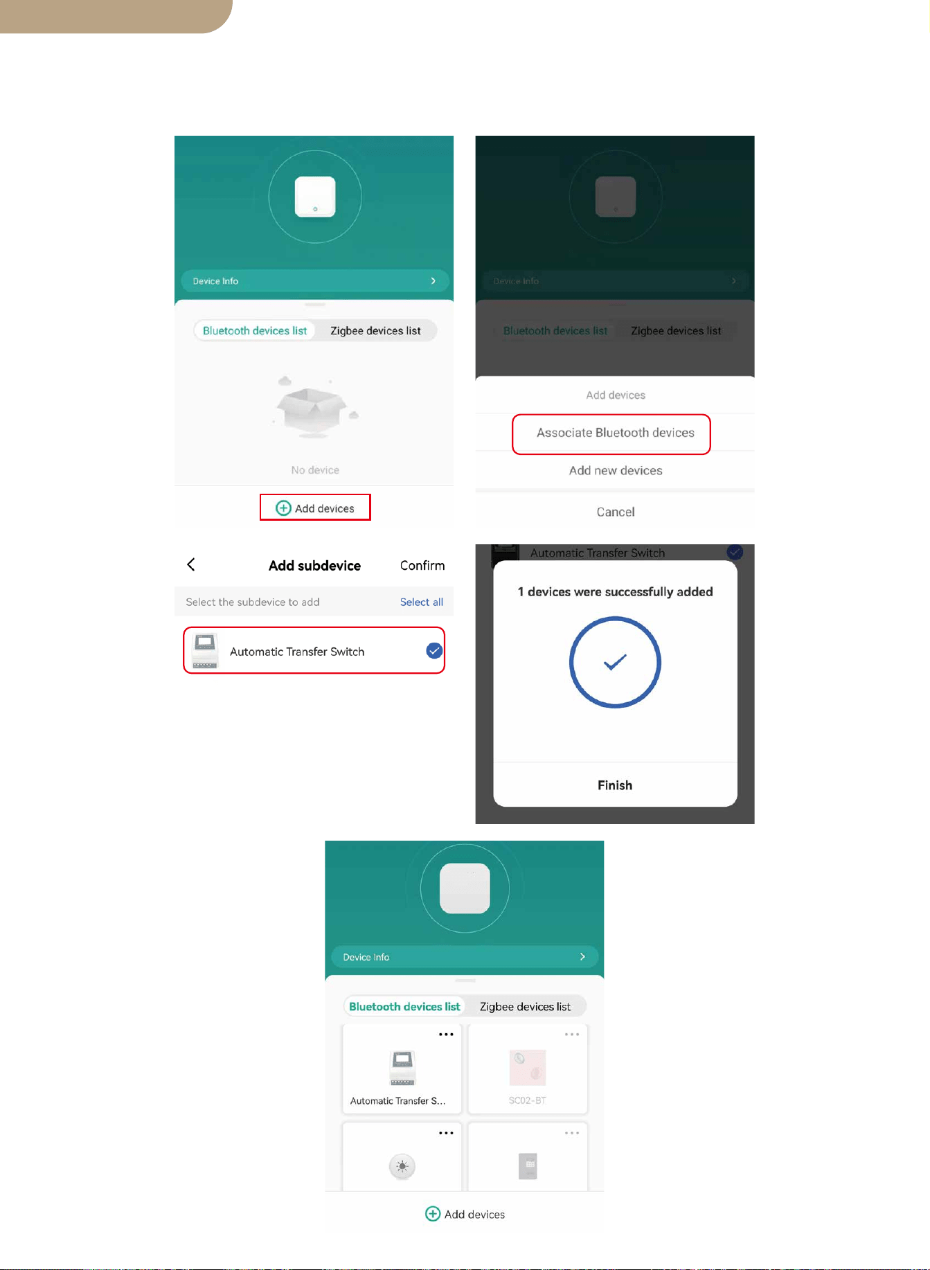
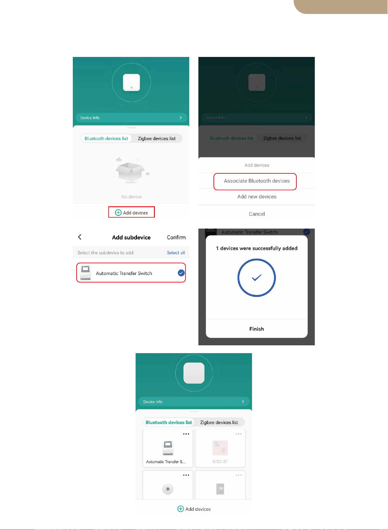
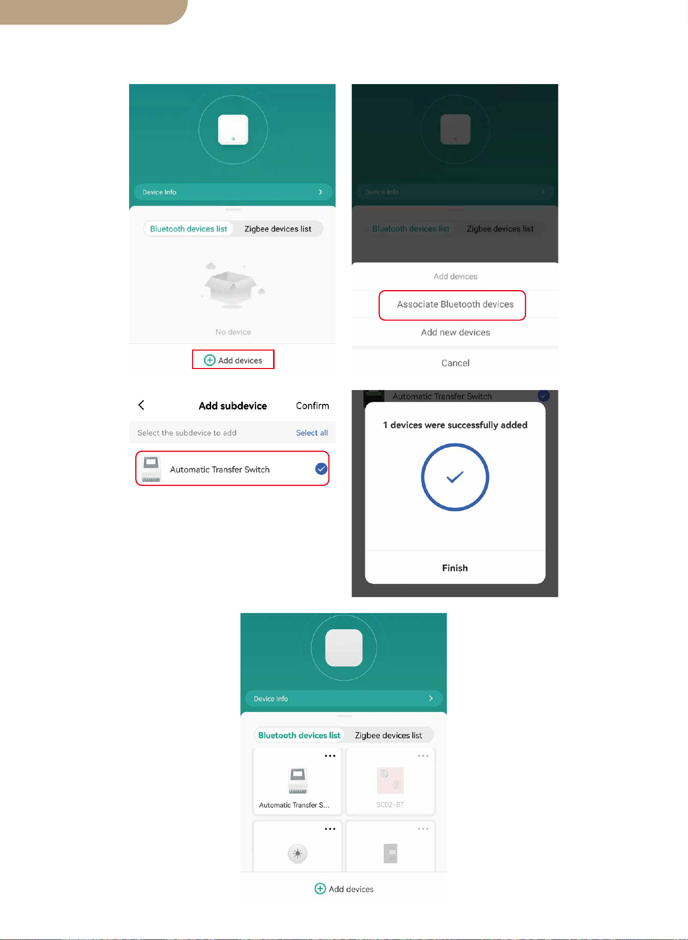
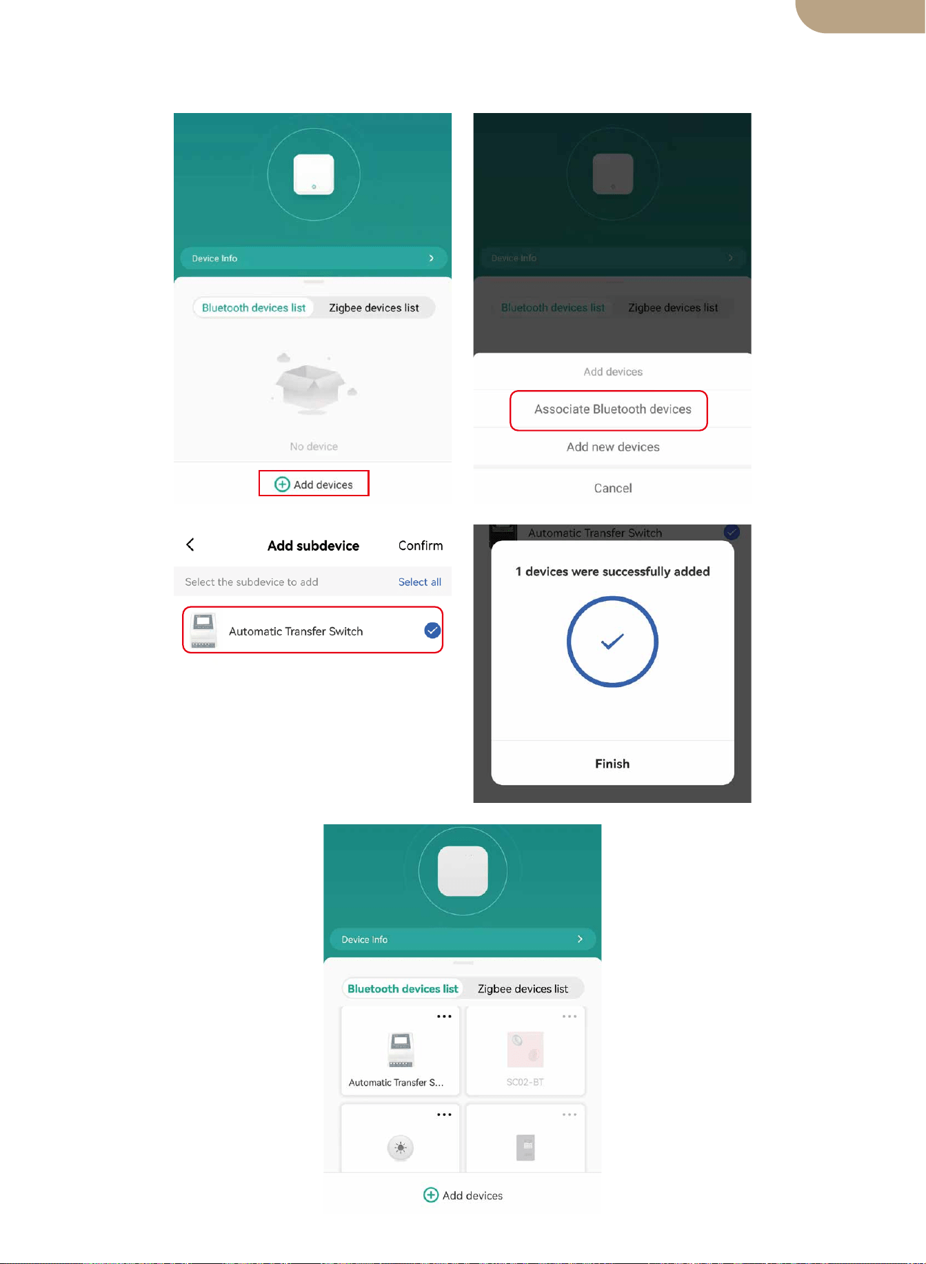
5. Open the Bluetooth gateway, click “Add devices”, click “Associate Bluetooth devic-
es”, select the device, and click “Add finish”.
12
English version

SAFETY RECOMENDATIONS
Environmental Protection
THE FOLLOWING SAFETY RECOMENDATIONS AND HAZARD WARNINGS
PROVIDE FOR THE PROTECTION OF THE ATS
CONTROLLER AND THE SAFETY OF THE USER
1. Failure to install and use this ATS Controller in a safe and proper manner, and failing
to adhere to all required Electrical Standards may result in Electrocution and/or Death.
Consult a Licensed/Experienced Electrician for any Questions regarding the Safe and
Correct Installation and continued use of this product.
2. This Power Controller should be mounted in a secure location and only authorized
individuals should be granted access to it.
3. Check the power transfer controller in connection cables before starting operation,
and periodically. If you detect any damage (i.e. transport or shipping damage) to the
power transfer controller, do not install or attempt to use. Notify your shipper immedi-
ately. Damaged connection cables must be replaced immediately.
4. When installing and using this ATS controller, it must not be subjected to or exposed
to the following conditions at any time. Electrical Shock/Fire/Explosion/Internal and/or
External Damage to the Device can occur.
a) ambient temperatures above 50℃ (122°F).
b) presence of flammable gases.
c) flammable solvents.
d) ignitable vapors
e) relative humidity in excess of 80%.
f) moisture contact and or water spray of any type.
5. Do not install or use the ATS controller near ignition sources, open fire or other heat
sources such as heaters, gas stoves or direct solar radiation. The manufacturer
reserves the right to make alterations, modifications and or additions to both this
manual and to the product.
13
At the end of its useful life, this product must not be disposed of together with normal
household waste, but has to be dropped off at a collection center for the recycling of
electrical devices.
The materials of this product are recyclable. With the reuse, the recycling of the mate-
rials or other forms of scrap usage, you are making an important contribution to pro-
tect the environment.
BG06
English version
Interruptor de transferencia automática inteligente ATS
Manual de usuario
versión en español

Dimensiones del producto
Diagrama de conexión
Especificaciones técnicas ATS
Notas de instalación
Solicitud
Introducción del producto
Instalación
Emparejamiento de dispositivos
Rango de voltaje de selección automática
Funciones de los botones
Selección de función de visualización
LCD luz de fondo
Especificaciones de trabajo del sistema 12v
Especificaciones de trabajo del sistema 24v
Especificaciones de trabajo del sistema 48v
Agregar dispositivos
Restablecimiento del dispositivo
Modelo
Contenido
Muchas gracias por elegir nuestros productos.
Lea este manual detenidamente antes de instalar y operar el interruptor de trans-
ferencia automática inteligente de doble potencia.
Tenga en cuenta TODAS las recomendaciones de seguridad.
01
02
03
03
04
04
04
04
05
pantalla LCD
05
06
06
Ajuste de errores
06
07
07
07
07
08
08
08
Recomendaciones de seguridad
12
Protección del medio ambiente
12
versión en español
Dimensiones del producto
Calibre máximo del cable: AWG 14 (2.5 mm²)
Calibre máximo del cable: AWG 6 (16 mm²)
01
versión en español
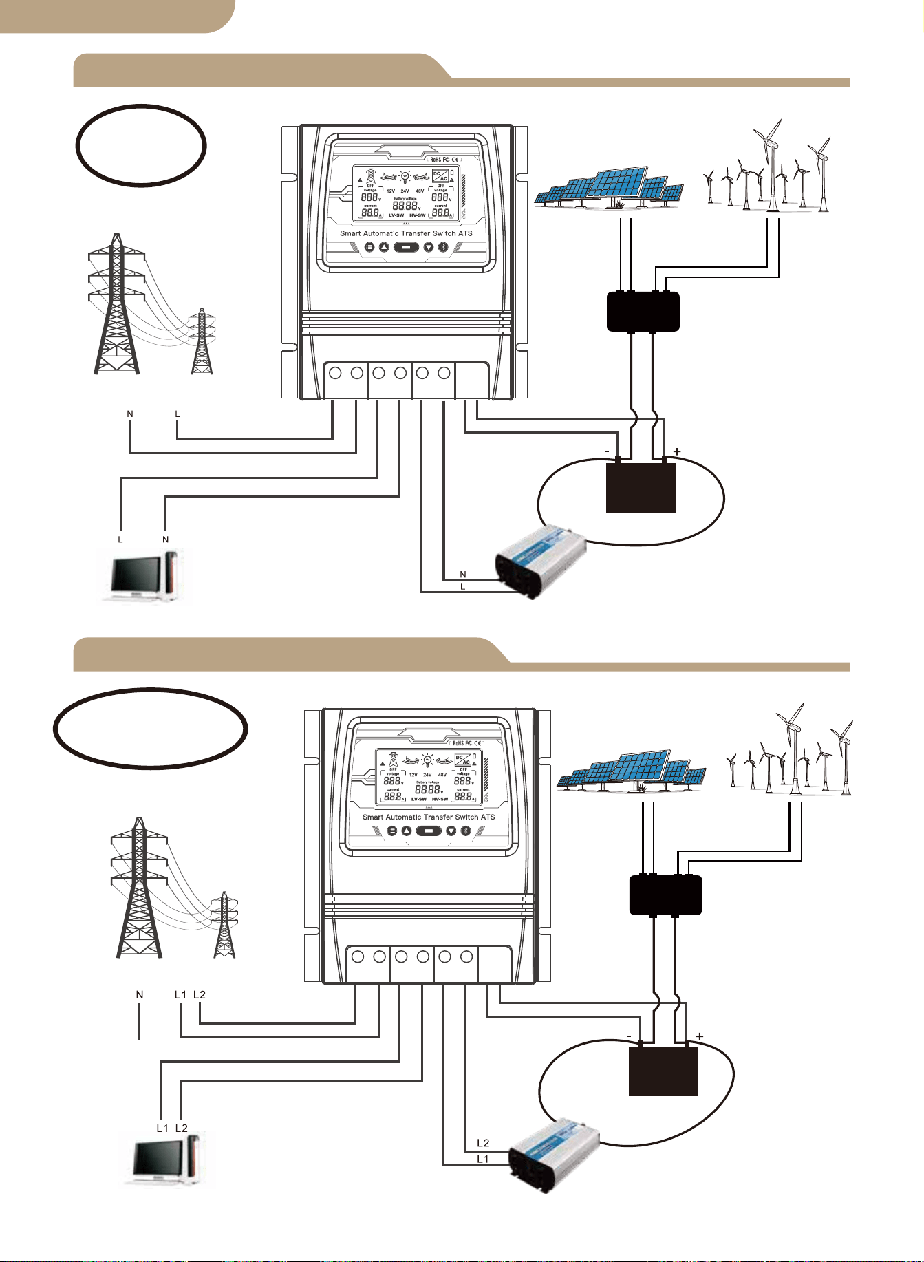
Diagrama de conexión L+N
L1+L2+N Esquema de conexión
Controlador solar
y eólico
Panel solar
Generador de viento
Energía de la red
Carga
Inversor
Batería
Vivo+Neutral
Energía de la red
Controlador solar
y eólico
Panel solar
Generador de viento
Carga
Inversor
Batería
En vivo1+En vivo2
+Neutro
02
Nota:
La batería es imprescindible para el
suministro de energía.
Nota:
La batería es imprescindible para el
suministro de energía.
versión en español
L N L N L N - +
L L L L L L - +
versión en español
Notas de instalación
03

Especificaciones técnicas
8kw (Energía de red 100-120V)
16kw (Energía de red 220-240V)
Selección automática:
CA 100-120V o CA 220-240V
Tiempo de transferencia del inversor a la red eléctrica ≦ 10ms
Tiempo de transferencia de energía de la red pública al inversor ≦ 16ms
Modelo
Potencia nominal
Voltaje de entrada
Tensión de salida
Tiempo de
transferencia
Pantalla LCD
Voltaje del sistema
Solicitud
Tamaño del
producto
N.W/PC
BAT-80A
Voltaje de la batería;
Fuente de alimentación:
Utilidad energía o batería-inversor.
Selección automática: 12V o 24V o 48V
Predeterminado: 10.5v/21v/42v, ajustable
Predeterminado: 12.5v/25v/50v, ajustable
19*17*7.25 cm (7.4”*6.7”*2.8” pulgadas)
1.32 kg (2.9 libras)
Puntos de ajuste de
transferencia de bajo
voltaje de la batería
Puntos de ajuste de
recuperación de
batería
Sistema solar fuera de la red;
Generador eólico;
Generador hidroeléctrico
Selección automática:
CA 100-120V o CA 220-240V
04
versión en español

Solicitud
Introducción del producto
Instalación
Rango de voltaje de selección automática
El controlador de transferencia de energía ATS proporciona una operación confiable de un
inversor y la energía de la red pública de CA en un dispositivo compacto. El ATS cambia
automáticamente entre la energía de la red pública de CA y el inversor, mientras protege al
inversor contra voltajes externos.
El controlador de transferencia de energía dual se usa entre un sistema de energía fuera de
la red y el suministro de energía de la red pública. El controlador ATS se conecta por sepa-
rado a 1) energía de la red pública 2) inversor 3) batería 4) carga La interfaz de usuario
permite monitorear tanto la Estado de funcionamiento del ATS y ajuste de los puntos de
ajuste de voltaje El interruptor maestro de encendido/apagado está ubicado en la parte
superior del controlador para facilitar el acceso.
El diseño de su sistema fuera de la red y la instalación de este interruptor de transfer-
encia solo deben ser realizados por usuarios finales calificados, electricistas o técnicos
autorizados y autorizados según lo exijan los códigos locales.
Antes de instalar este dispositivo, revise este manual en su totalidad antes de comenzar.
Instale / monte el controlador ATS en una superficie limpia y seca, y en una ubicación
adecuada que permita la libre circulación de aire alrededor del ATS en todo momento.
Asegúrese de que todos los cables tengan la longitud adecuada para permitir un alivio
de tensión adecuado en el bloque de conexión del ATS.
Asegúrese de que se sigan todos los protocolos de seguridad Verifique que todas las
fuentes de alimentación de CA estén apagadas y aseguradas con un sistema de etique-
ta de bloqueo de seguridad para evitar la activación accidental de energía.
Todos los cables de conexión eléctrica deben cumplir con las recomendaciones de
calibre mínimo establecidas por los requisitos eléctricos estándar y los códigos locales.
¡Verifique que todas las conexiones estén conectadas y apretadas correctamente! Las
conexiones eléctricas sueltas se sobrecalentarán y pueden dañar el ATS y causar incen-
dios.
No conecte el conector neutro del lado del usuario a una conexión a tierra o a un
conector de protección a tierra, ya que los tomacorrientes del usuario no tienen conex-
ión a tierra de protección múltiple.
Nota: No conecte el cable de puesta a tierra “pe” (tierra de protección) al conector
neutro.
Después de asegurarse de que se hayan cumplido los pasos anteriores y de haber
verificado que todas las conexiones están correctamente terminadas, proceda con las
conexiones finales a la alimentación de la red pública, el inversor, la batería y la (s)
carga (s).
Encienda el interruptor principal ubicado en la parte superior del ATS.
Realice verificaciones de voltaje y amperímetro en su sistema recién instalado para
verificar que su ATS esté funcionando dentro de los parámetros operativos especifica-
dos.
1.
2.
3.
4.
5.
6.
7.
8.
9.
10.
05
Rango de voltaje de detección del sistema de 12V 9V-17V
Rango de voltaje de detección del sistema de 24V 18V-30V
Rango de voltaje de detección del sistema de 48V 30V-60V
versión en español
Pantalla LCD
Modelo
06
Estado de red de cambio de modo
automático
Estado del inversor de cambio de
modo automático
1. Cuando se muestra LV-SW, se trata de la interfaz de funciones para ajustar la tensión de
conmutación de baja tensión de la batería.
2. Cuando se muestra HV-SW, es la interfaz de funciones para ajustar la tensión de recuperación
de baja tensión de la batería.
3. 12V, 24V, 48V son las tensiones de visualización correspondientes después de ser identifica-
das por el sistema.
4. La flecha de la derecha muestra el cambio a la energía pública, y la rejilla interna
parpadea para mostrar el estado de salida actual, no se muestra cuando no hay salida de
corriente.
5. La flecha de la izquierda muestra el cambio al inversor, y la rejilla interna parpadea
para mostrar el estado de la salida de corriente, no se muestra cuando no hay salida de corriente.
6. El icono de la batería muestra el estado de conmutación de baja tensión con un rendimiento
intermitente.
7. Se muestra con un rendimiento intermitente cuando hay un fallo de corriente alterna sin
tensión.
8.
Pantalla de cuadrícula
correspondiente en
voltaje y corriente de CA.
Pantalla del inversor
correspondiente en
voltaje y corriente de CA.
versión en español
Selección de función de pantalla
Ajuste de errores
Botones clave del panel frontal:
a. Botón de modo
b. botón más
c. Botón de función
d. Botón menos
e. Botón de configuración de la aplicación
Funciones de los botones
a b c d e
a.Botón de modo: cambia entre el modo automático, el modo de alimentación de red y
b.El botón más solo es válido para el ajuste de voltaje (0.1V por disparo).
c.Botón de función: Establece el voltaje LV-SW, el voltaje HV-SW y el voltaje de la
d.El botón menos solo es válido para el ajuste de voltaje (0.1 V por disparador).
e.Botón de configuración de la aplicación: manténgalo pulsado durante 6s para entrar
Si ocurre algún valor de voltaje de error, mantenga presionado el botón Agregar y el botón
menos al mismo tiempo durante 3 segundos para liberar el parpadeo de voltaje de 0.0V.
Presione el botón Agregar o Menos para modificar el valor de voltaje de error de detección.
botón de función durante 3 segundos después de la modificación para guardar el valor modifi-
cado.
① Cuando la configuración de la función muestra la interfaz BAT-V (pantalla predeterminada
del sistema), el sistema de pantalla digital LCD rastrea en tiempo real el voltaje de la batería.
② Cuando la configuración de la función muestra la interfaz LV-SW, el voltaje del interruptor
de bajo voltaje de la pantalla digital LED (valor predeterminado), luego presione el botón para
aumentar o modificar el valor predeterminado, presione y mantenga presionado el botón de
función durante 3 segundos para guardar y modifique el valor, después de que la pantalla LCD
cambie a la interfaz BAT-V predeterminada.
③ Cuando la configuración de la función muestra la interfaz HV-SW, el LED digital muestra el
voltaje de recuperación de bajo voltaje (valor predeterminado), luego presione el botón para
aumentar o modificar el valor predeterminado, mantenga presionado el botón de función
durante 3 segundos para guardar el modificado valor, después de que la pantalla LCD cambie
a la interfaz BAT-V predeterminada.
07
Estado de la fuente de alimentación
del inversor
Estado de energía de la red pública
versión en español
el modo de alimentación del inversor.
batería para cambiar cuando se presiona el botón. El voltaje de la batería se muestra de
forma predeterminada cuando el dispositivo está encendido. Si no hay una señal de
activación en la interfaz de configuración, la interfaz de visualización predeterminada se
restaurará después de 10 segundos.
en el estado de distribución de red, el indicador azul parpadea
La luz de fondo de la pantalla LCD se apagará automáticamente si NO se detecta
actividad en los botones después de 60 segundos.
Al presionar cualquier botón, se iluminará nuevamente la pantalla LCD durante 60 segundos.
Tenga en cuenta que el panel LCD NO mostrará/iluminará ni funcionará hasta que el
ATS esté correctamente conectado al circuito de fuente de batería de alimentación de
CC requerido del voltaje mínimo detectado.
Esta es una función de seguridad del ATS.
-------------------------------------------------------------------
LCD luz de fondo
Especificaciones de trabajo del sistema de 12V
Especificaciones de trabajo del sistema de 24V
Especificaciones de funcionamiento del sistema de 48V
08
A. Pantalla LCD de nivel de batería.
B. Corte de detección y tensión de punto de recuperación
Cuando se detecta que el voltaje de la batería es inferior a 10.5V durante 2 segundos (el
sistema predeterminado es 11V), es el voltaje de conmutación de bajo voltaje y la acción de
conmutación es:
LCD- la flecha hacia la derecha parpadea, la pantalla LCD- la flecha hacia la
izquierda está apagada, el icono de la batería parpadea.
Cuando se detecta un aumento de voltaje de la batería de 12.5V durante 2 segundos (valor
predeterminado del sistema de 13.5V), es el voltaje de recuperación de bajo voltaje y la acción
de conmutación es:
LCD- la flecha hacia la derecha está apagada, la pantalla LCD- la flecha
hacia la izquierda parpadea, el icono de la batería parpadea.
A. Pantalla LCD de nivel de batería.
B. Corte de detección y tensión de punto de recuperación
Cuando se detecta que el voltaje de la batería es inferior a 21V durante 2 segundos (el siste-
ma predeterminado es 22V), es el voltaje de conmutación de bajo voltaje y la acción de con-
mutación es:
LCD- la flecha hacia la derecha parpadea, la pantalla LCD- la flecha hacia la
izquierda está apagada, el icono de la batería parpadea.
Al detectar un aumento de voltaje de la batería de 25V durante 2 segundos (valor predetermi-
nado del sistema de 27V), es el voltaje de recuperación de bajo voltaje y la acción de con-
mutación es:
LCD- la flecha hacia la derecha está apagada, la pantalla LCD- la flecha
hacia la izquierda parpadea, el icono de la batería parpadea.
A. Pantalla LCD de nivel de batería.
B. Corte de detección y tensión de punto de recuperación
Cuando se detecta que el voltaje de la batería es inferior a 42V durante 2 segundos (44V por
defecto del sistema), es el voltaje de conmutación de bajo voltaje y la acción de conmutación
es:
LCD- la flecha hacia la derecha parpadea, la pantalla LCD- la flecha hacia la
izquierda está apagada, el icono de la batería parpadea.
Al detectar un aumento de voltaje de la batería de 50V durante 2 segundos (valor predetermi-
nado del sistema de 54V), es el voltaje de recuperación de bajo voltaje y la acción de con-
mutación es:
LCD- la flecha hacia la derecha está apagada, la pantalla LCD- la flecha
hacia la izquierda parpadea, el icono de la batería parpadea.
versión en español
Agregar dispositivos
Restablecimiento del dispositivo
② Registro o Iniciar sesión.
• Descarga la aplicación “MOES”.
• Ingrese a la interfaz Registrarse/Iniciar sesión, toque “Registrarse” para crear una
cuenta ingresando su número de teléfono para obtener el código de verificación y “Es-
tablecer contraseña”. Elija “Iniciar sesión” si ya tiene una cuenta de MOES.
③ Configure la aplicación para el conmutador.
• Preparación: asegúrese de que el interruptor se haya conectado a la electricidad,
asegúrese de que su teléfono se haya conectado a Wi-Fi y pueda conectarse a Internet.
Mantenga presionado el botón durante aproximadamente 6 segundos, el indicador azul
en el interruptor parpadea rápidamente después de 3 segundos. La reparación se
realizó correctamente.
Emparejamiento de dispositivos
Método uno:
Escanea el código QR para configurar la guía de red.
09
versión en español
① Descargue la aplicación MOES en App store o escanee el código QR
La aplicación MOES se ha actualizado y es mucho más compatible
que la aplicación Tuya Smart/Smart Life, y es más funcional para
el control de escenas por Siri, el widget y las recomendaciones de
escenas como el nuevo servicio personalizado.
(
Nota: La aplicación Tuya Smart/Smart Life sigue funcionando,
pero la aplicación MOES es muy recomendable)
Método dos:
1. Asegúrese de que el dispositivo se haya reiniciado.
⑴ ⑵
Escanea el código QR Conecte el dispositivo de acuerdo
con el proceso de configuración.
10
versión en español
2. Asegúrese de que su teléfono esté conectado a Wi-Fi y Bluetooth.
3. Abra la aplicación Smart Life/Tuya y haga clic en “+”, luego la página de aviso se
mostrará automáticamente en la pantalla. Haga clic en “Ir a agregar”.
4. Agregue el dispositivo con éxito, puede editar el nombre del dispositivo para ingre-
sar a la página del dispositivo haciendo clic en “Listo”.
11
versión en español
5. Abra la puerta de enlace Bluetooth, haga clic en “Agregar dispositivos”, haga clic en
“Asociar dispositivos Bluetooth”, seleccione el dispositivo y haga clic en “Agregar
finalizar”.
12
versión en español

RECOMENDACIONES DE SEGURIDAD
Protección del medio ambiente
LAS SIGUIENTES RECOMENDACIONES DE SEGURIDAD Y ADVERTENCIAS DE
PELIGRO
PROVEER PARA LA PROTECCIÓN DE LOS ATS
RESPONSABLE Y LA SEGURIDAD DEL USUARIO
1. No instalar y usar este controlador ATS de manera segura y adecuada, y no cumplir
con todos los estándares eléctricos requeridos puede resultar en electrocución y/o
muerte. Consulte a un electricista con licencia/experiencia si tiene preguntas sobre la
instalación segura y correcta. y el uso continuado de este producto.
2. Este Power Controller debe montarse en un lugar seguro y solo se debe permitir el
acceso a personas autorizadas.
3. Verifique el controlador de transferencia de energía en los cables de conexión antes
de iniciar la operación, y periódicamente. Si detecta algún daño (es decir, daños
durante el transporte o el envío) en el controlador de transferencia de energía, no lo
instale ni intente usarlo. Notifique a su transportista de inmediato. Conexión dañada
los cables deben ser reemplazados inmediatamente.
4. Al instalar y utilizar este controlador ATS, no debe someterse ni exponerse a las
siguientes condiciones en ningún momento: Pueden producirse descargas eléctricas,
incendios, explosiones, daños internos o externos al dispositivo.
a) Temperaturas ambiente superiores a 50℃ (122℉).
b) presencia de gases inflamables.
c) disolventes inflamables.
d) vapores inflamables
e) humedad relativa superior al 80%.
f) contacto con la humedad y/o rocío de agua de cualquier tipo.
5. No instale ni use el controlador ATS cerca de fuentes de ignición, fuego abierto u
otras fuentes de calor como calentadores, estufas de gas o radiación solar directa. El
fabricante se reserva el derecho de realizar alteraciones, modificaciones o adiciones
tanto a este manual como a el producto.
13
Al final de su vida útil, este producto no debe desecharse junto con los residuos
domésticos normales, sino que debe depositarse en un centro de recogida para el
reciclaje de aparatos eléctricos.
Los materiales de este producto son reciclables. Con la reutilización, el reciclaje de los
materiales u otras formas de uso de chatarra, está haciendo una contribución impor-
tante para proteger el medio ambiente.
BG06
versión en español

Smart Automatic Transfer Switch ATS
Benutzerhandbuch
Deutsche Fassung

Produktabmessungen
Schaltplan
ATS Technische Daten
Installationshinweise
Anwendung
Produkteinführung
Installation
Gerätepaarung
Spannungsbereich automatisch auswählen
Tastenfunktionen
Funktionsauswahl anzeigen
LCD-Rücklicht
Arbeitsspezifikation des 12-V-Systems
Arbeitsspezifikation des 24-V-Systems
Arbeitsspezifikation des 48-V-Systems
Geräte hinzufügen
Gerät zurückgesetzt
Modell
Inhalt
Vielen Dank, dass Sie sich für unsere Produkte entschieden haben.
Bitte lesen Sie dieses Handbuch sorgfältig durch, bevor Sie den Dual Power
Smart Automatic Transfer Switch installieren und in Betrieb nehmen.
Bitte beachten Sie ALLE Sicherheitsempfehlungen.
01
02
03
03
04
04
04
04
05
LCD Bildschirm
05
06
06
Fehlerausgleich
06
07
07
07
07
08
08
08
Sicherheitsempfehlungen
12
Umweltschutz
12
Deutsche Fassung
Produktabmessungen
Maximaler Drahtquerschnitt: AWG 14 (2.5 mm²)
Maximaler Drahtquerschnitt: AWG 6 (16 mm²)
01
Deutsche Fassung
L+N Anschlussplan
L1+L2+N Anschlussplan
Solar- und Windregler
Sonnenkollektor
Windgenerator
Versorgungsstrom
Belastung
Wandler
Batterie
Live+Neutral
Versorgungsstrom
Solar- und Windregler
Sonnenkollektor
Windgenerator
Belastung
Wandler
Batterie
Live1+Live2+Neutral
02
Notiz:
Die Batterie ist ein Muss für die
Stromversorgung.
Notiz:
Die Batterie ist ein Muss
für die Stromversorgung.
Deutsche Fassung
L N L N L N - +
L L L L L L - +
Installationshinweise
03
Deutsche Fassung

Technische Spezifikationen
8 kW (Nutzleistung 100–120 V)
16 kW (Netzstrom 220–240 V)
Automatische Auswahl:
AC 100-120V oder AC 220-240V
Übergangszeit des Wechselrichters zum Netzstrom ≦ 10ms
Übertragungszeit des Netzstroms zum Wechselrichter ≦ 16ms
Modell
Nennleistung
Eingangsspannung
Ausgangsspannung
Transferzeit
LCD Bildschirm
Systemspannung
Anwendung
Produktgröße
N.W/PC
BAT-80A
Batteriespannung; Stromquelle: Dienstprogramm
Power oder Batterie-Wechselrichter.
Automatische Auswahl:
12V oder 24V oder 48V
Standard: 10.5V/21V/42V, einstellbar
Standard: 12.5V/25V/50V, einstellbar
19 * 17 * 7.25 cm (7.4" * 6.7" * 2.8" in)
1.32 kg (2.9 Pfund)
Schaltsollwerte
für niedrige
Batteriespannung
Batterieerholungs-
Sollwerte
Netzunabhängiges Solarsystem;
Windgenerator; Hydrogenerator
Automatische Auswahl:
AC 100-120V oder AC 220-240V
04
Deutsche Fassung

Anwendung
Produkteinführung
Installation
Spannungsbereich automatisch auswählen
Der ATS Power Transfer Controller stellt den zuverlässigen Betrieb eines Wechselrich-
ters und des AC-Netzstroms in einem kompakten Gerät dar. Der ATS schaltet autom-
atisch zwischen dem AC-Netzstrom und dem Wechselrichter um und schützt den
Wechselrichter gleichzeitig vor externen Spannungen.
Der Dual Power Transfer Controller wird zwischen einem netzunabhängigen Stromver-
sorgungssystem und der Stromversorgung des öffentlichen Versorgungsunternehmens
verwendet. Der ATS-Controller wird separat an 1) Netzstrom 2) Wechselrichter 3)
Batterie 4) Last angeschlossen. Die Benutzeroberfläche ermöglicht sowohl die Über-
wachung der ATS-Betriebszustand und Einstellen der Spannungssollwerte Der
Haupt-EIN/AUS-Schalter befindet sich für einfachen Zugang oben auf der Steuerung.
Das Design Ihres Off-Grid-Systems und die Installation dieses Transferschalters sollten nur
von qualifizierten Endbenutzern, Elektrikern oder Technikern durchgeführt werden, die
autorisiert und lizenziert sind, wenn dies nach örtlichen Vorschriften erforderlich ist.
Bitte lesen Sie dieses Handbuch vor der Installation dieses Geräts vollständig durch, bevor
Sie beginnen.
Installieren/montieren Sie den ATS-Controller auf einer sauberen und trockenen Oberfläche
und an einem geeigneten Ort, an dem jederzeit eine freie Luftzirkulation um den ATS
möglich ist. Stellen Sie sicher, dass alle Kabel ausreichend lang sind, um eine ordnungs-
gemäße Zugentlastung am ATS-Anschlussblock zu ermöglichen.
Stellen Sie sicher, dass alle Sicherheitsprotokolle befolgt werden Prüfen Sie, ob alle
Wechselstromversorgungen ausgeschaltet und mit einem Sicherheitsverriegelungssystem
gesichert sind, um eine unbeabsichtigte Aktivierung der Stromversorgung zu verhindern.
Alle Stromanschlusskabel müssen den Empfehlungen für den Mindestdrahtquerschnitt
entsprechen, die durch standardmäßige elektrische Anforderungen und Ihre örtlichen
Vorschriften festgelegt sind.
Vergewissern Sie sich, dass alle Anschlüsse richtig angeschlossen und festgezogen sind!
Lose elektrische Anschlüsse überhitzen und können den ATS beschädigen und Brände
verursachen.
Verbinden Sie den neutralen Stecker auf der Benutzerseite nicht mit dem Erdungsanschluss
oder mit einem Schutzerdungsanschluss, da die Benutzersteckdosen keine Schutz-Mehr-
facherdung haben.
Hinweis: Schließen Sie den “pe”-Erdungsdraht (Schutzerde) nicht an den neutralen
Anschluss an.
Nachdem Sie sich vergewissert haben, dass die oben genannten Schritte eingehalten
wurden und Sie überprüft haben, dass alle Anschlüsse ordnungsgemäß abgeschlossen sind,
fahren Sie mit den endgültigen Anschlüssen an die Stromversorgung, den Wechselrichter,
die Batterie und die Last (en) fort.
Schalten Sie den Hauptschalter oben am ATS ein.
Führen Sie Spannungs- und Amperemeterprüfungen an Ihrem neu installierten System
durch, um sicherzustellen, dass Ihr ATS innerhalb der angegebenen Betriebsparameter
arbeitet.
1.
2.
3.
4.
5.
6.
7.
8.
9.
10.
05
12V-Systemerkennungsspannungsbereich 9V-17V
24V-Systemerkennungsspannungsbereich 18V-30V
48V-Systemerkennungsspannungsbereich 30V-60V
Deutsche Fassung
LCD Bildschirm
Modell
06
Automatischer Modus zum Umschalten
des Netzstatus
Umschaltzustand des Wechselrichters
im automatischen Modus
1. Wenn LV-SW angezeigt wird, handelt es sich um die Funktionsschnittstelle zur Einstel-
lung der Batterie-Unterspannungs-Schaltspannung.
2. Wenn HV-SW angezeigt wird, handelt es sich um die Funktionsschnittstelle zur Einstel-
lung der Batterieunterspannungswiederkehrspannung.
3.12V, 24V, 48V sind die entsprechenden Anzeigespannungen, die vom System ermittelt
wurden.
4. Der rechte Pfeil zeigt das Umschalten auf die öffentliche Stromversorgung an,
und das interne Gitter blinkt, um den aktuellen Ausgangszustand anzuzeigen, keine
Anzeige, wenn kein Strom ausgegeben wird.
5. Der linke Pfeil zeigt die Umschaltung auf den Wechselrichter an, und das
interne Gitter blinkt, um den aktuellen Ausgangszustand anzuzeigen; keine Anzeige, wenn
kein Strom ausgegeben wird.
6.
Das Batteriesymbol zeigt den Schaltzustand der Unterspannung durch Blinken
an.
7. Wird mit blinkender Leistung angezeigt, wenn der Nicht-Spannungs-Wechselstrom
ausfällt.
8.
Entsprechende Netzan-
zeige bei Wechselspan-
nung und-strom.
Entsprechende Wechsel-
richteranzeige auf
AC-Spannung und
-Strom.
Deutsche Fassung
Auswahl der Anzeigefunktion
Fehlerkorrektur
Tasten auf der Vorderseite:
a. Modus-Taste
b. Plus-Taste
c. Funktionstaste
d. Minus-Taste
e. APP-Konfigurationsschaltfläche
Tastenfunktionen
a b c d e
Modustaste: Umschalten zwischen Automatikmodus, Netzversorgungsmodus und
Wechselrichterversorgungsmodus.
Die Plus-Taste gilt nur für die Spannungseinstellung
(0.1 V pro Auslösung).
Funktionstaste: Legt die LV-SW-Spannung, HV-SW-Spannung und Batteriespannung
fest, die beim Drücken der Taste durchlaufen werden. Die Batteriespannung wird stan-
dardmäßig angezeigt, wenn das Gerät eingeschaltet wird. Wenn auf der Einstel-
lungsschnittstelle kein Triggersignal vorhanden ist, wird die Standardanzeigeschnittstelle
nach 10 Sekunden wiederhergestellt.
Die Minus-Taste gilt nur für die Spannungseinstellung (0.1 V pro Trigger).
APP-Konfigurationsschaltfläche: Drücken und halten Sie die Taste für 6 Sekunden, um
den Netzwerk-Verteilungsstatus zu aktivieren. Die blaue Anzeige blinkt.
Wenn ein Fehlerspannungswert auftritt, halten Sie die Add-Taste und die Minus-Taste
gleichzeitig 3 Sekunden lang gedrückt, um das 0.0V-Spannungsflackern zu beseitigen.
Drücken Sie die Add-oder Minus-Taste, um den Spannungswert des Erkennungsfe-
hlers zu ändern. Drücken und halten Sie die Funktionstaste für 3 Sekunden nach der
Änderung, um den geänderten Wert zu speichern.
① Wenn die Funktionseinstellung die BAT-V-Schnittstelle anzeigt (Systemstandardanzeige), verfolgt
das digitale LCD-Anzeigesystem die Batteriespannung in Echtzeit.
② Wenn die Funktionseinstellung die LV-SW-Schnittstelle anzeigt, die LED-Digitalanzeige Nieder-
spannungsschalterspannung (Standardwert), drücken Sie dann die Taste, um den Standardwert zu
erhöhen oder zu ändern, und halten Sie die Funktionstaste 3 Sekunden lang gedrückt, um zu speichern
und Ändern Sie den Wert, nachdem das LCD zur Standard-BAT-V-Schnittstelle gewechselt hat.
③ Wenn die Funktionseinstellung die HV-SW-Schnittstelle anzeigt, die LED-Digitalanzeige Nieder-
spannungswiederherstellungsspannung (Standardwert), drücken Sie dann die Taste, um den Stan-
dardwert zu erhöhen oder zu ändern, und halten Sie die Funktionstaste 3 Sekunden lang gedrückt, um
die Änderung zu speichern Wert, nachdem das LCD auf die Standard-BAT-V-Schnittstelle umges-
chaltet hat.
07
Status der Stromversorgung des
Wechselrichters
Netzstromstatus
Deutsche Fassung
a.
b.
c.
d.
e.
Die Hintergrundbeleuchtung des LCD-Displays schaltet sich automatisch aus, wenn
nach 60 Sekunden KEINE Tastenbetätigung erkannt wird.
Durch Drücken einer beliebigen Taste wird das LCD-Display erneut für 60 Sekunden
beleuchtet.
Bitte beachten Sie: Das LCD-Panel wird NICHT angezeigt/beleuchtet oder funktioniert,
bis der ATS ordnungsgemäß an den erforderlichen Gleichstrom-Batteriequellenstrom-
kreis mit der erkannten Mindestspannung angeschlossen ist.
Dies ist eine Sicherheitsfunktion des ATS.
-------------------------------------------------------------------
LCD-Rücklicht
Arbeitsspezifikation des 12V-Systems
Arbeitsspezifikation des 24V-Systems
48V-System-Arbeitsspezifikation
08
A. Batteriestand-LCD-Anzeige.
b. Erkennungsabschaltung und Erholungspunktspannung
Wenn erkannt wird, dass die Batteriespannung 2 Sekunden lang unter 10.5V liegt
(Systemstandard 11V), ist dies die Niederspannungsschaltspannung und die Schaltak-
tion ist:
LCD- Rechtspfeil blinkt, LCD- Linkspfeilanzeige ausgeschaltet, Batter-
iesymbol blinkt.
Wenn der Anstieg der Batteriespannung um 12.5V für 2 Sekunden (Systemstandard
13.5V) erkannt wird, ist dies die Niederspannungs-Wiederherstellungsspannung, und
die Schaltaktion ist:
LCD- Rechtspfeilanzeige ausgeschaltet, LCD- Linkspfeil blinkt, Batter-
iesymbol blinkt aus.
A. Batteriestand-LCD-Anzeige.
b. Erkennungsabschaltung und Erholungspunktspannung
Wenn erkannt wird, dass die Batteriespannung 2 Sekunden lang unter 21V liegt (Sys-
temstandard 22V), handelt es sich um die Niederspannungs-Schaltspannung, und die
Schaltaktion ist:
LCD- Rechtspfeil blinkt, LCD- Linkspfeilanzeige ausgeschaltet, Batter-
iesymbol blinkt.
Wenn der Batteriespannungsanstieg 2 Sekunden lang um 25V (Systemstandard 27V)
erkannt wird, ist dies die Niederspannungs-Wiederherstellungsspannung, und die
Schaltaktion ist:
LCD- Rechtspfeilanzeige ausgeschaltet, LCD- Linkspfeil blinkt, Batter-
iesymbol blinkt aus.
A. Batteriestand-LCD-Anzeige.
b. Erkennungsabschaltung und Erholungspunktspannung
Wenn erkannt wird, dass die Batteriespannung 2 Sekunden lang unter 42V liegt (Sys-
temstandard 44V), handelt es sich um die Niederspannungs-Schaltspannung, und die
Schaltaktion ist:
LCD- Rechtspfeil blinkt, LCD- Linkspfeilanzeige ausgeschaltet, Batter-
iesymbol blinkt.
Wenn der Anstieg der Batteriespannung 2 Sekunden lang um 50V (Systemstandard
54V) erkannt wird, ist dies die Niederspannungs-Wiederherstellungsspannung, und die
Schaltaktion ist:
LCD- Rechtspfeilanzeige ausgeschaltet, LCD- Linkspfeil blinkt, Batter-
iesymbol blinkt aus.
Deutsche Fassung
Geräte hinzufügen
Geräte-Reset
② Registrierung oder Einloggen.
• Laden Sie die Anwendung “MOES” herunter.
• Rufen Sie die Registrierungs-/Anmeldeschnittstelle auf; tippen Sie auf “Registrie-
ren”, um ein Konto zu erstellen, indem Sie Ihre Telefonnummer eingeben, um den
Bestätigungscode zu erhalten, und “Passwort festlegen”. Wählen Sie “Anmelden”,
wenn Sie bereits ein MOES-Konto haben.
③ Konfigurieren Sie die APP für den Switch.
• Vorbereitung: Stellen Sie sicher, dass der Switch mit Strom verbunden ist, stellen Sie
sicher, dass Ihr Telefon mit Wi-Fi verbunden ist und eine Verbindung zum Internet
herstellen kann.
Halten Sie die Taste etwa 6 Sekunden lang gedrückt, die blaue Anzeige auf dem
Schalter blinkt nach 3 Sekunden schnell, die erneute Kopplung war erfolgreich.
Gerätepaarung
Methode eins:
Scannen Sie den QR-Code, um den Netzwerkführer zu konfigurieren.
09
Deutsche Fassung
① Laden Sie die MOES App im App Store herunter oder scannen Sie den QR-Code
Die MOES App ist viel kompatibler als die Tuya
Smart/Smart Life App und funktioniert auch für die
Steuerung von Szenen durch Siri, Widgets und Szenene-
mpfehlungen als völlig neuer, maßgeschneiderter Service.
(
Hinweis: Tuya Smart/Smart Life App funktioniert noch,
aber MOES App ist sehr empfehlenswert)
Methode zwei:
1. Stellen Sie sicher, dass das Gerät zurückgesetzt wurde.
⑴ ⑵
Scannen Sie den QR-Code Bitte schließen Sie das Gerät gemäß
dem Konfigurationsprozess an.
10
Deutsche Fassung
2. Stellen Sie sicher, dass Ihr Telefon mit Wi-Fi und Bluetooth verbunden ist.
3. Öffnen Sie die Smart Life/Tuya App und klicken Sie auf “+”, dann wird die Eing-
abeaufforderungsseite automatisch auf dem Bildschirm angezeigt. Klicken Sie auf
“Zum Hinzufügen”.
4. Fügen Sie das Gerät erfolgreich hinzu. Sie können den Namen des Geräts bearbeit-
en, um die Geräteseite aufzurufen, indem Sie auf “Fertig” klicken.
11
Deutsche Fassung
5. Öffnen Sie das Bluetooth-Gateway, klicken Sie auf “Geräte hinzufügen”, klicken Sie
auf “Bluetooth-Geräte zuordnen”, wählen Sie das Gerät aus und klicken Sie auf
“Fertig stellen”.
12
Deutsche Fassung

SICHERHEITSEMPFEHLUNGEN
Umweltschutz
DIE FOLGENDEN SICHERHEITSEMPFEHLUNGEN UND GEFAHRENHINWEISE
SORGEN SIE FÜR DEN SCHUTZ DES ATS
CONTROLLER UND DIE SICHERHEIT DES BENUTZERS
1. Wenn dieser ATS-Controller nicht sicher und ordnungsgemäß installiert und verwen-
det wird und nicht alle erforderlichen elektrischen Standards eingehalten werden, kann
dies zu einem Stromschlag und/oder Tod führen. Wenden Sie sich bei Fragen zur
sicheren und korrekten Installation an einen zugelassenen/erfahrenen Elektriker und
fortgesetzte Verwendung dieses Produkts.
2. Dieser Leistungsregler sollte an einem sicheren Ort montiert werden und nur autori-
sierten Personen sollte Zugang dazu gewährt werden.
3. Überprüfen Sie die Verbindungskabel des Power Transfer Controllers vor der Inbe-
triebnahme und in regelmäßigen Abständen. Wenn Sie Schäden (z. B. Transport- oder
Transportschäden) am Power Transfer Controller feststellen, installieren Sie ihn nicht
und versuchen Sie nicht, ihn zu verwenden. Benachrichtigen Sie sofort Ihren Spediteur.
Beschädigte Verbindung Kabel müssen sofort ersetzt werden.
4. Bei der Installation und Verwendung dieses ATS-Controllers darf er zu keiner Zeit
den folgenden Bedingungen ausgesetzt oder ausgesetzt werden: Stromschlag/Feuer/-
Explosion/interne und/oder externe Schäden am Gerät können auftreten.
a) Umgebungstemperaturen über 50℃ (122℉).
b) Anwesenheit von brennbaren Gasen.
c) brennbare Lösungsmittel.
d) zündfähige Dämpfe.
e) relative Luftfeuchtigkeit über 80%.
f) Feuchtigkeitskontakt und/oder Spritzwasser jeglicher Art.
5. Installieren oder verwenden Sie den ATS-Controller nicht in der Nähe von Zündquel-
len, offenem Feuer oder anderen Wärmequellen wie Heizungen, Gasherden oder direk-
ter Sonneneinstrahlung. Der Hersteller behält sich das Recht vor, Änderungen, Modi-
fikationen und/oder Ergänzungen sowohl an dieser Anleitung als auch an dieser vorzu-
nehmen das Produkt.
13
Dieses Produkt darf am Ende seiner Lebensdauer nicht zusammen mit dem normalen
Hausmüll entsorgt werden, sondern muss an einer Sammelstelle für das Recycling von
Elektrogeräten abgegeben werden.
Die Materialien dieses Produkts sind recycelbar. Durch die Wiederverwendung, das
Recycling der Materialien oder andere Formen der Schrottverwertung leisten Sie einen
wichtigen Beitrag zum Schutz der Umwelt.
BG06
Deutsche Fassung
Comutador de Transferência Automática Inteligente ATS
Manual do usuário
versão em português

Dimensões do produto
Diagrama de ligação
Especificações Técnicas ATS
Notas de instalação
Inscrição
Introdução do produto
Instalação
Pareamento do dispositivo
Faixa de tensão de seleção automática
Funções do botão
Seleção de função de exibição
Luz de fundo do LCD
Especificação de funcionamento do sistema 12v
Especificação de funcionamento do sistema 24v
Especificação de funcionamento do sistema 48v
Adicionar dispositivos
Redefinição do dispositivo
Modelo
Conteúdo
Muito obrigado por escolher nossos produtos.
Por favor, revise este manual cuidadosamente antes de instalar e operar o Dual
Power Smart Automatic Transfer Switch.
Observe TODAS as recomendações de segurança.
01
02
03
03
04
04
04
04
05
tela de LCD
05
06
06
Ajuste de erro
06
07
07
07
07
08
08
08
Recomendações de segurança
12
Proteção Ambiental
12
versão em português
Dimensões do produto
Bitola Máxima do Fio: AWG 14 (2.5mm²)
Bitola Máxima do Fio: AWG 6 (16mm²)
01
versão em português
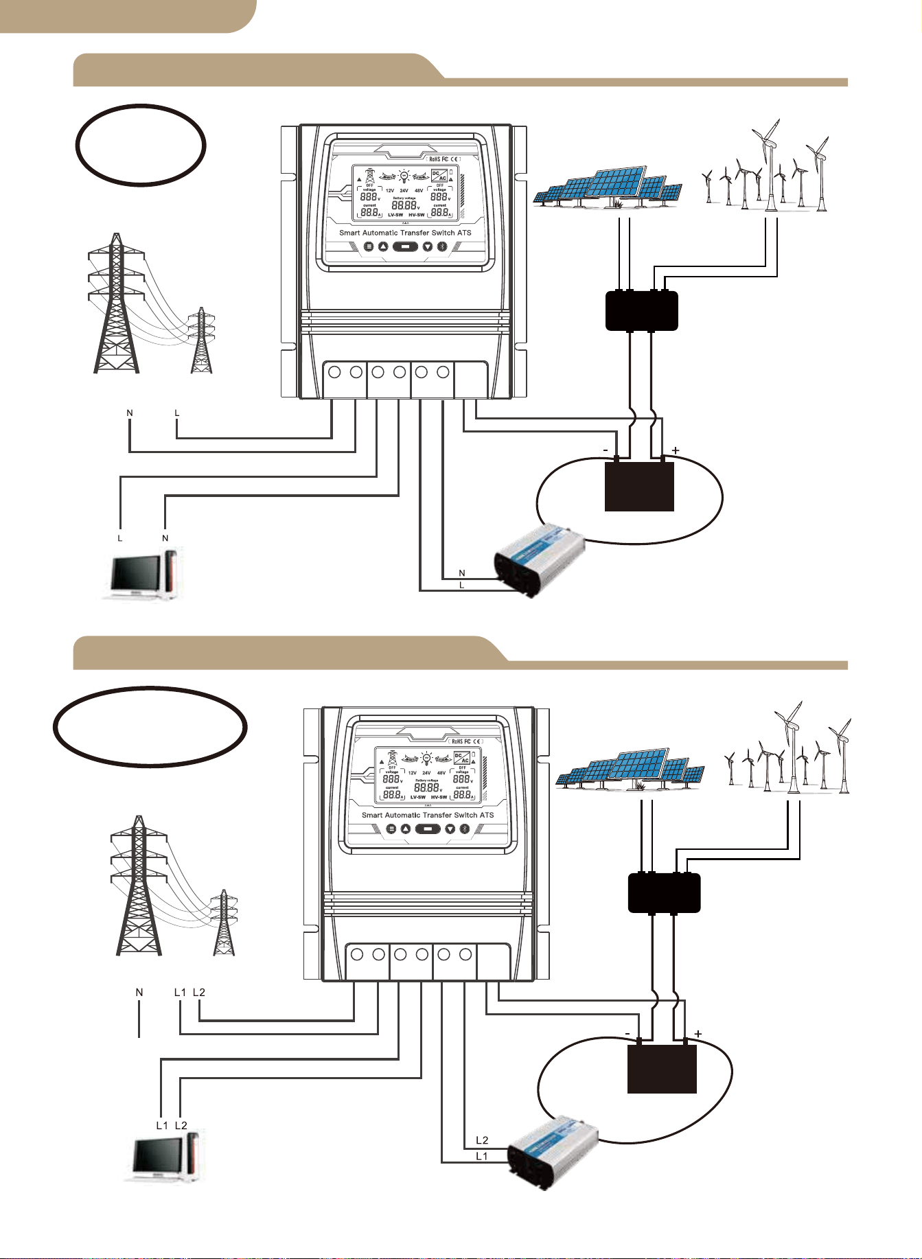
Diagrama de conexão L+N
Diagrama de conexão L1+L2+N
Controlador Solar
e Eólico
Painel solar
Gerador de energia eólica
Energia Utilitária
Carregar
Inversor
Bateria
Ao vivo
+Neutro
Energia Utilitária
Controlador Solar
e Eólico
Painel solar
Gerador de energia eólica
Carregar
Inversor
Bateria
Ao vivo1+Ao vivo2
+Neutro
02
Observação:
A bateria é uma obrigação para
a fonte de alimentação.
Observação:
A bateria é uma obrigação para
a fonte de alimentação.
versão em português
L N L N L N - +
L L L L L L - +
versão em português
Notas de instalação
03

Especificações técnicas
8kw (Energia Utilitária 100-120V)
16kw (Energia Utilitária 220-240V)
Seleção automática:
AC 100-120V ou AC 220-240V
Tempo de transferência do inversor para a energia da concessionária ≦ 10ms
Tempo de transferência de energia da concessionária para o inversor ≦ 16ms
Modelo
Potência nominal
Tensão de entrada
Voltagem de saída
Tempo de
transferência
Tela de LCD
Tensão do Sistema
Inscrição
Tamanho do produto
N.W/PC
BAT-80A
Tensão da bateria; Fonte de alimentação:
Utilitário energia ou inversor de bateria.
Seleção automática: 12V ou 24V ou 48V
Padrão: 10.5v/21v/42v, ajustável
Padrão: 12.5v/25v/50v, ajustável
19*17*7.25 cm (7.4”*6.7”*2.8” pol)
1.32KG (2.9 libras)
Pontos de ajuste de
transferência de baixa
tensão da bateria
Pontos de ajuste de
recuperação de
bateria
Sistema solar fora da rede;
Gerador eólico; Gerador hidrelétrico
Seleção automática:
AC 100-120V ou AC 220-240V
04
versão em português

Inscrição
Introdução do produto
Instalação
Faixa de tensão de seleção automática
O controlador de transferência de energia ATS fornece operação confiável de um
inversor e energia elétrica CA em um dispositivo compacto.O ATS alterna automatica-
mente entre a energia elétrica CA e o inversor, enquanto protege o inversor contra
tensões externas.
O controlador de transferência de energia duplo é usado entre um sistema de energia
fora da rede e a fonte de alimentação de serviço público. O controlador ATS se
conecta separadamente a 1) energia de serviço público 2) inversor 3) bateria 4) carga.
A interface do usuário permite o monitoramento do Estado Operacional ATS e Ajuste
de Tensão Setpoints A Chave Master ON/OFF está localizada na parte superior do
controlador para fácil acesso.
O projeto de seu sistema off-grid e a instalação desta chave de transferência
devem ser realizados apenas por usuários finais qualificados, eletricistas ou técnic-
os autorizados e licenciados quando exigido pelos códigos locais.
Antes de instalar este dispositivo, revise este manual na íntegra antes de começar.
Instale / monte o controlador ATS em uma superfície limpa e seca e em um local
adequado que permita a circulação de ar livre ao redor do ATS o tempo todo.
Certifique-se de que todos os cabos tenham comprimento adequado para permitir
o alívio de tensão adequado no bloco de conexão ATS .
Certifique-se de que todos os protocolos de segurança sejam seguidos. Verifique
se todas as fontes de alimentação CA estão desligadas e protegidas com um
sistema de etiqueta de trava de segurança para evitar a atuação inadvertida de
energia.
Todos os cabos de conexão de energia devem atender às recomendações mínimas
de bitola de fio definidas pelos requisitos elétricos padrão e seus códigos locais.
Verifique se todas as conexões estão conectadas e apertadas corretamente! Con-
exões elétricas soltas irão superaquecer e podem danificar o ATS e causar incên-
dios.
Não conecte o conector neutro do lado do usuário à conexão de aterramento ou a
um conector de aterramento de proteção, pois as tomadas do usuário não pos-
suem aterramento múltiplo de proteção.
Nota: Não conecte o fio terra “pe” (terra de proteção) ao conector neutro.
Depois de garantir que as etapas acima foram cumpridas e você verificou que
todas as conexões estão terminadas corretamente, prossiga com as conexões
finais à energia da rede elétrica, inversor, bateria e carga (s).
Ligue o interruptor principal localizado na parte superior do ATS.
Realize verificações de voltagem e amperímetro em seu sistema recém-instalado
para verificar se seu ATS está operando dentro dos parâmetros operacionais espe-
cificados.
1.
2.
3.
4.
5.
6.
7.
8.
9.
10.
05
Faixa de tensão de detecção do sistema 12V 9V-17V
Faixa de tensão de detecção do sistema 24V 18V-30V
Faixa de tensão de detecção do sistema 48V 30V-60V
versão em português
Tela de LCD
Modelo
06
Status da grade de comutação de
modo automático
Estado do inversor de comutação de
modo automático
1. Quando o LV-SW é exibido, é a interface de função para definir a tensão de comutação
de baixa tensão da bateria.
2. Quando HV-SW é apresentado, é a interface de função para a definição da tensão de
recuperação da bateria de baixa tensão.
3.12V, 24V, 48V são as tensões de visualização correspondentes após respectivamente
identificadas pelo sistema.
4. A seta para a direita mostra a mudança para a alimentação pública,e a rede
interna pisca para mostrar o estado de saída de corrente,sem visualização quando não há
saída de corrente.
5. A seta esquerda mostra a comutação para o inversor, e a rede interna pisca
para mostrar o estado de saída de corrente, sem mostrador quando não há saída de
corrente.
6. O ícone da bateria mostra o estado de comutação de baixa voltagem com desem-
penho intermitente.
7. Exibido com desempenho intermitente quando há falha de corrente alternada sem
voltagem.
8.
Exibição de grade corre-
spondente na tensão e
corrente CA.
Exibição do inversor
correspondente na
tensão e corrente CA.
versão em português
Seleção da função de exibição
Ajuste de erro
Funções do botão
Botões das teclas do painel frontal:
a. Botão de modo
b. Botão de adição
c. Botão de função
d. Botão menos
e. Botão de configuração do aplicativo
a b c d e
Botão de modo: alternar entre o modo automático, modo de alimentação de rede, e
modo de alimentação do inversor.
O botão mais é válido apenas para configuração de tensão (0.1V por disparo).
Botão de função: Define a voltagem LV-SW, voltagem HV-SW e voltagem da bateria
para alternar quando o botão é pressionado. A tensão da bateria é exibida por
padrão quando o dispositivo é ligado. Se não houver sinal de disparo na interface de
configuração, a interface de exibição padrão será restaurada após 10 segundos.
O botão menos é válido apenas para configuração de tensão (0.1 V por gatilho).
Botão de configuração do aplicativo: premir e manter premido durante 6s para entrar
no estado de distribuição da rede, o indicador azul pisca.
Se ocorrer algum valor de tensão de erro, pressione e segure o botão adicionar e o
botão menos ao mesmo tempo por 3 segundos para liberar a oscilação de tensão de
0.0V. Pressione o botão adicionar ou menos para modificar o valor da tensão de erro
de detecção. Pressione e segure o botão botão de função por 3 segundos após a
modificação para salvar o valor modificado.
① Quando a configuração da função exibe a interface BAT-V (exibição padrão do
sistema), o sistema de exibição digital LCD é o rastreamento em tempo real da tensão
da bateria.
② Quando a configuração da função exibir a interface LV-SW, a tensão do interruptor
de baixa tensão do display digital LED (valor padrão), pressione o botão para aumen-
tar ou modificar o valor padrão, pressionando e segurando o botão de função por 3
segundos para salvar e modifique o valor, após o LCD mudar para a interface padrão
BAT-V.
③ Quando a configuração da função exibir a interface HV-SW, a tensão de recuper-
ação de baixa tensão do display digital LED (valor padrão), pressione o botão para
aumentar ou modificar o valor padrão, pressionando o botão de função por 3 segun-
dos para salvar o modificado valor, após o LCD mudar para a interface BAT-V padrão.
07
Status da fonte de alimentação do
inversor
Status de energia do utilitário
versão em português
a.
b.
c.
d.
e.
A luz de fundo do visor LCD desliga-se automaticamente se a atividade do botão NÃO
for detectada após 60 segundos.
Pressionar qualquer botão iluminará novamente o visor LCD por 60 segundos.
Observe que o painel LCD NÃO exibirá/iluminará ou funcionará até que o ATS esteja
conectado corretamente ao circuito de fonte de bateria de alimentação CC necessária
de tensão mínima detectada.
Esta é uma função de segurança do ATS.
-------------------------------------------------------------------
Luz de fundo do LCD
Especificação de funcionamento do sistema de 12V
Especificação de funcionamento do sistema 24V
Especificação de funcionamento do sistema de 48V
08
a. Visor LCD do nível da bateria.
b. Detecção de corte e tensão do ponto de recuperação
Quando é detectado que a tensão da bateria é inferior a 10.5V por 2 segundos (pa-
drão do sistema 11V), é a tensão de comutação de baixa tensão e a ação de comu-
tação é:
LCD- seta para a direita pisca, LCD- seta para a esquerda desligada,
ícone da bateria pisca.
Ao detectar o aumento da tensão da bateria 12.5V por 2 segundos (padrão do sistema
13.5V), é a tensão de recuperação de baixa tensão e a ação de comutação é:
LCD- Seta para a direita desligada, LCD- seta para a esquerda piscando,
ícone da bateria piscando.
a. Visor LCD do nível da bateria.
b. Detecção de corte e tensão do ponto de recuperação
Quando é detectado que a tensão da bateria é inferior a 21V por 2 segundos (padrão
do sistema 22V), é a tensão de comutação de baixa tensão e a ação de comutação é:
LCD- seta para a direita pisca, LCD- seta para a esquerda desligada,
ícone da bateria pisca.
Ao detectar o aumento da tensão da bateria 25V por 2 segundos (padrão do sistema
27V), é a tensão de recuperação de baixa tensão e a ação de comutação é:
LCD- Seta para a direita desligada, LCD- seta para a esquerda piscando,
ícone da bateria piscando.
a. Visor LCD do nível da bateria.
b. Detecção de corte e tensão do ponto de recuperação
Quando é detectado que a tensão da bateria é inferior a 42V por 2 segundos (padrão
do sistema 44V), é a tensão de comutação de baixa tensão e a ação de comutação é:
LCD- seta para a direita pisca, LCD- seta para a esquerda desligada,
ícone da bateria pisca.
Ao detectar o aumento da tensão da bateria 50V por 2 segundos (padrão do sistema
54V), é a tensão de recuperação de baixa tensão e a ação de comutação é:
LCD- Seta para a direita desligada, LCD- seta para a esquerda piscando,
ícone da bateria piscando.
versão em português
Adicionar dispositivos
Reinicialização do dispositivo
② Cadastro ou Login.
• Baixe o aplicativo “MOES”.
• Entre na interface Cadastro/Login, toque em “Registrar” para criar uma conta dig-
itando seu número de telefone para obter o código de verificação e “Definir senha.”
Escolha “Login” se você já possui uma conta MOES.
③ Configure o APP para o switch.
• Preparação: Certifique-se de que o switch foi conectado à eletricidade, certifique-se
de que seu telefone esteja conectado ao Wi-Fi e seja capaz de se conectar à Internet.
Pressione e segure o botão por cerca de 6 segundos, o indicador azul no interruptor
pisca rapidamente após 3 segundos. O emparelhamento foi bem-sucedido.
Emparelhamento de dispositivos
Método um:
Digitalize o código QR para configurar o guia de rede.
09
versão em português
① Descarregar a aplicação MOES na App Store ou digitalizar o código QR
MOES App é actualizado com muito mais compatibilidade
do que o Tuya Smart/Smart Life App, funcionando bem
para a cena controlada por Siri, widget e recomendações
de cena como o serviço totalmente novo personalizado.
(
Nota: A aplicação Tuya Smart/Smart Life ainda funciona,
mas a aplicação MOES é altamente recomendada)
Método dois:
1. Certifique-se de que o dispositivo foi reiniciado.
⑴ ⑵
Digitalize o código QR Por favor, conecte o dispositivo de acordo
com o processo de configuração.
10
versão em português
2. Certifique-se de que seu telefone esteja conectado a Wi-Fi e Bluetooth.
3. Abra o aplicativo Smart Life/Tuya e clique em “+”, então a página de prompt apa-
recerá automaticamente na tela. Clique em “Ir para adicionar”.
4. Adicione o dispositivo com sucesso, você pode editar o nome do dispositivo para
entrar na página do dispositivo clicando em “Concluído”.
11
versão em português
5. Abra o gateway Bluetooth, clique em “Adicionar dispositivos”, clique em “Associar
dispositivos Bluetooth”, selecione o dispositivo e clique em “Adicionar acabamento”.
12
versão em português

RECOMENDAÇÕES DE SEGURANÇA
Proteção Ambiental
AS SEGUINTES RECOMENDAÇÕES DE SEGURANÇA E AVISOS DE PERIGO
FORNECER PARA A PROTEÇÃO DO ATS
CONTROLADOR E SEGURANÇA DO USUÁRIO
1. A falha em instalar e usar este Controlador ATS de maneira segura e adequada e
não cumprir todos os Padrões Elétricos exigidos pode resultar em eletrocussão e/ou
morte. Consulte um eletricista licenciado/experiente para quaisquer dúvidas sobre a
instalação segura e correta e uso continuado deste produto.
2. Este Power Controller deve ser montado em um local seguro e somente pessoas
autorizadas devem ter acesso a ele.
3. Verifique o controlador de transferência de energia nos cabos de conexão antes de
iniciar a operação e periodicamente. Se você detectar algum dano (ou seja, danos de
transporte ou transporte) no controlador de transferência de energia, não instale ou
tente usar. Notifique seu remetente imediatamente. Conexão danificada os cabos
devem ser substituídos imediatamente.
4. Ao instalar e usar este controlador ATS, ele não deve ser submetido ou exposto às
seguintes condições em nenhum momento: Choque elétrico/incêndio/explosão/danos
internos e/ou externos ao dispositivo podem ocorrer.
a) Temperaturas ambientes acima de 50℃ (122℉).
b) presença de gases inflamáveis.
c) solventes inflamáveis.
d) vapores inflamáveis
e) umidade relativa superior a 80%.
f) contato com umidade e ou spray de água de qualquer tipo.
5. Não instale ou use o controlador ATS perto de fontes de ignição, fogo aberto ou
outras fontes de calor, como aquecedores, fogões a gás ou radiação solar direta. o
produto.
13
No final da sua vida útil, este produto não deve ser eliminado juntamente com o lixo
doméstico normal, devendo ser entregue num centro de recolha para reciclagem de
aparelhos elétricos.
Os materiais deste produto são recicláveis, com a reutilização, a reciclagem dos ma-
teriais ou outras formas de aproveitamento de sucata, você está dando uma impor-
tante contribuição para a proteção do meio ambiente.
BG06
versão em português
スマートATS電源自動切替器
ユーザーマニュアル
日本語版

製品の寸法
接続図
ATS技術仕様
インストールに関する注意事項
応用
製品導入
インストール
電圧範囲の自動選択
コンテンツ
弊社製品をお選びいただき、誠にありがとうございます。
デュアルパワースマート自動転送スイッチの取り付けを操作する前に、このマニュア
ルを注意深く確認してください。
すべての安全に関する事項にご注意ください。
01
02
03
03
04
04
04
04
LCDディスプレイ
05
デバイスのペアリング
主な機能
表示機能の選択
LCDバックライト
12vシステムの動作仕様
24vシステム動作仕様
48vシステム動作仕様
デバイスを追加する
デバイスのリセット
06
06
エラー調整
06
07
07
07
07
08
08
08
安全に関する注意事項
12
環境を守ること
12
日本語版
製品の寸法
最大ワイヤゲージ:AWG 14(2.5mm²)
最大ワイヤゲージ:AWG 6(16mm²)
01
日本語版
L+N接続図
L1 + L2+N接続図
ソーラー&ウィンド
コントローラー
ソーラーペネル
風力発電機
商用電源
ロード
インバーター
バッテリー
電圧線
+中性線
商用電源
ソーラー&ウィンド
コントローラー
ソーラーペネル
風力発電機
ロード
インバーター
バッテリー
電圧線1+電圧線2
+中性線
02
ノート:
バッテリーは電源の必需品です。
ノート:
バッテリーは電源の必需品です。
日本語版
L N L N L N - +
L N L N L N - +
L L L L L L - +
日本語版
インストールに関する注意事項
03

技術仕様
8kw(ユーティリティパワー100-120V)
16kw(ユーティリティパワー220-240V)
自動選択:AC100-120VまたはAC220-240V
商用電源へのインバーター転送時間 ≦ 10ms
インバーターへの商用電力伝送時間 ≦ 16ms
型番
定格出力
入力電圧
出力電圧
転送時間
LCDディスプレイ
システム電圧
応用
商品のサイズ
NW / PC
BAT-80A
バッテリー電圧; 電源:商用電源または
バッテリーインバーター
自動選択:12V/24V/48V
デフォルト:10.5V/21V/42V、調整可能
デフォルト:12.5V/25V/50V、調整可能
19*17*7.25cm(7.4”*6.7”*2.8”in)
1.32KG(2.9ポンド)
バッテリーの低電圧
転送設定値
バッテリー回復設定値
オフグリッドソーラーシステム;
風力発電機; 水力発電機
自動選択:AC100-120VまたはAC220-240V
04
日本語版

応用
製品導入
インストール
電圧範囲の自動選択
ATS電源切替コントローラーは、1つのコンパクトなデバイスでインバーターとAC商用電
源の信頼性の高い動作を提供します。ATSは、インバーターを外部電圧から保護しなが
ら、AC商用電源とインバーターを自動的に切り替えます。
本製品は、オフグリッド電源システムと商用電源の間で使用されます。ATSコントロー
ラーは、1)商用電源2)インバーター3)バッテリー4)負荷に個別に接続しま
す。ユーザーインターフェイスでは、 ATSの動作状態と電圧設定値の調整の両方が可能
です。マスターON/OFFスイッチは、デバイスの上部にあります。
オフグリッドシステムの設計とこのデバイスの設置は、資格のあるエンドユーザー、電
気技師、または地域の法令で義務付けられている場合に認可および認可された技術者の
みが行う必要があります。
このデバイスをインストールには、作業を開始する前にこのマニュアル全体を確認して
ください。
ATS コントローラーを清潔で乾燥した表面に、空気の循環性が良い場所に設置 / 取り
付けてください。ATS 接続ブロックで適切なストレインリリーフを可能にするために、
すべてのケーブルが適切な長さであることを確認してください。
すべての安全プロトコルに従っていることを確認します。不注意による電源の作動を防
ぐために、すべての AC 電源がオフになっていて、安全ロックアウトタグシステムで固
定されていることを確認てください。
すべての電源接続ケーブルは、標準の電気要件および地域の法令によって設定された最
小ワイヤゲージ仕様を満たしている必要があります。
すべての接続が正しく接続され、締められていることを確認してください。電気接続が
緩んでいると、過熱して ATS が損傷し、火災が発生する可能性があります。
カスタマーソケットには保護用の複数のアースがないため、カスタマー側の中性線コネ
クタをアース接続または保護アースコネクタに接続しないでください。
注:「pe」アース線(保護アース)を中性線コネクタに接続しないでください。
上記の手順が順守されていることを確認し、すべての接続が適切に終了していることを
確認したら、商用電源、インバーター、バッテリー、および負荷への最終接続に進みます。
ATS の上部にあるマスタースイッチをオンにします。
新しくインストールしたシステムで電圧と電流計のチェックを実行して、ATS が指定
された動作パラメーター内で動作していることを確認します。
1.
2.
3.
4.
5.
6.
7.
8.
9.
10.
05
12Vシステム検出電圧範囲9V-17V
24Vシステム検出電圧範囲18V-30V
48Vシステム検出電圧範囲30V-60V
日本語版
LCDディスプレイ
モデル
06
商用電源給電に切り替えている 電池給電に切り替えている
1.LV-SW 切り替える電圧値を設定する。
2.HV-SW 逆切り替える電圧値を設定する。
3.12V、24V、48Vの電圧がそれぞれシステムにに識別された後、インターフェースに対
応するシステム電圧が表示されます。
4. 右矢印は、商用電源給電状態。
5. 左矢印は、電池給電状態。
6. バッテリーアイコンの点滅は、バッテリーが低電圧、切り替える状態を表示しま
す。
7. AC電圧が検出されてない、または電圧障害が出る場合、点滅する。
8.
商用電源によるAC電源電
圧の表示
インバーターによるAC電源
電圧の表示
日本語版
表示機能の選択
エラー調整
フロントパネルのボタン機能:
a. モードボタン
b. プラスボタン
c. ファンクションボタン
d. マイナスボタン
e. アプリ設定ボタン
主な機能
a b c d e
モードボタン:自動モード、系統電源モード、インバータ電源モードの切替ができます。
プラスボタンは電圧設定(トリガーごとに0.1V)のみ有効です。
ファンクションボタン:ボタンを押したときに循環する LV-SW 電圧、HV-SW 電圧、バッ
テリー電圧を設定します。 デバイスの電源を入れると、バッテリー電圧がデフォルトで表
示されます。 設定インターフェイスにトリガー信号がない場合、デフォルトの表示イン
ターフェイスは 10 秒後に復元されます。
マイナスボタンは電圧設定(1トリガーあたり0.1V)のみ有効です。
アプリ設定ボタン: ネットワークの配分の州、青い表示器のフラッシュを書き入れる 6s の
ための出版物そして把握
電圧値が正しくない場合は、プラスボタンとマイナスボタンを3秒間押し続けて、0.0Vの
電圧点滅を解除します。 プラスまたはマイナスボタンを押して、検出エラー電圧値を変
更します。 変更後、ファンクションボタンを3秒間押し続けて、変更した値を保存しま
す。
① 機能設定で BAT-V インターフェースが表示される場合(システムのデフォルト表示)、
LCD デジタルはバッテリー電圧をリアルタイムで表示します。
② 機能設定で LV-SW インターフェースが表示されている場合、LED デジタルは低電圧
の変更電圧(デフォルト値)を表示し、ボタンを押してデフォルト値を変更し、機能ボタ
ンを 3 秒間押し続けて変更内容を保存します。LCD がデフォルトの BAT-V インターフェー
スに戻ります。
③ 機能設定で HV-SW インターフェースが表示されている場合、LED デジタルは低電圧
の回復電圧(デフォルト値)を表示し、ボタンを押してデフォルト値を変更し、機能ボタ
ンを 3 秒間押し続けて変更内容を保存します。LCD がデフォルトの BAT-V インターフェー
スに戻ります。
07
電池給電状態 商用電源の状態
日本語版
a.
b.
c.
d.
e.
60秒経過しても操作が検出されない場合、LCDディスプレイのバックライトは自動的
にオフになります。
いずれかのボタンを押すと、LCDディスプレイが再び60秒間点灯します。
※LCDパネルは、デバイスがDC電源-バッテリー電源回路が適切に接続され、必要の最
小限の電圧が検出されるまで、表示/点灯または動作はしません。
これがATSの安全保護機能です。
-------------------------------------------------------------------
LCDバックライト
12Vシステムの動作仕様
24Vシステムの動作仕様
48Vシステムの動作仕様
08
a. バッテリーレベル -LCD ディスプレイ
b. 切り替える電圧値及び逆戻る電圧値の検出
バッテリー電圧が 2 秒間 10.5V 未満(システムデフォルトは 11V)であることが検出され
た場合、それは低電圧が切り替えるであり、スイッチング動作は次のとおり:
LCD- 右矢印が点滅し、LCD- 左矢印がオフになり、バッテリーアイコンが点
滅します。
バッテリー電圧が 12.5V に上昇し、2 秒間続くことが検出されると(システムデフォルトは
13.5V)、これは電圧が逆切り替えるであり、スイッチング動作表示は次のとり:
LCD- 右矢印表示がオフ、LCD- 左矢印が点滅、バッテリーアイコンが点滅停
止。
a. バッテリーレベル -LCD ディスプレイ
b. 切り替える電圧値及び逆戻る電圧値の検出
バッテリー電圧が 2 秒間 21V 未満(システムデフォルトは 22V)であることが検出された
場合、それは低電圧が切り替えるであり、スイッチング動作は次のとおり:
LCD- 右矢印が点滅し、LCD- 左矢印がオフになり、バッテリーアイコンが点
滅します。
バッテリー電圧が 25V に上昇し、2 秒間続くことが検出されると(システムデフォルトは
27V)、これは電圧が逆切り替えるであり、スイッチング動作表示は次のとり:
LCD- 右矢印表示がオフ、LCD- 左矢印が点滅、バッテリーアイコンが点滅停
止。
a. バッテリーレベル -LCD ディスプレイ。
b. 切り替える電圧値及び逆戻る電圧値の検出
バッテリー電圧が 2 秒間 42V 未満(システムデフォルトは 44V)であることが検出された
場合、それは低電圧が切り替えるであり、スイッチング動作は次のとおり:
LCD- 右矢印が点滅し、LCD- 左矢印オフになり、バッテリーアイコンが点滅
します。
バッテリー電圧が 50V に上昇し、2 秒間続くことが検出されると(システムデフォルトは
54V)、これは電圧が逆切り替えるであり、スイッチング動作表示は次のとり:
LCD- 右矢印表示がオフ、LCD- 左矢印が点滅、バッテリーアイコンが点滅停
止。
日本語版
デバイスの追加
デバイスのリセット
② 登録またはログイン。
• 「MOES」アプリをダウンロードします。
• 登録 / ログインインターフェースに入ります。「登録」をタップして電話番号を入力し、
確認コードと「パスワードの設定」を入力してアカウントを作成します。MOES アカウント
を既にお持ちの場合は、「ログイン」を選択します。
③ ペアリングについて。
• 準備:デバイス上部のスイッチがオンのことを確認してください。スマホの bluetooth
と Wi-Fi が有効になっており、インターネット(2.4GHzのみ)に接続されていることを確
認してください。
ボタンを約6秒間押し続けると、デバイスの青いインジケーターが3秒後に点滅状態にな
ります。リセットは成功しました同時に、ペアリング状態に入ります。
デバイスのペアリング
方法1:
デバイス追加のインターフェースに入り、QRコードをスキャンして、ネットワークガイ
ドを構成します。
09
日本語版
① MOESアプリをApp Storeでダウンロードするか、QRコードをスキャンしてください。
MOESアプリは、Tuya Smart/Smart Lifeアプリとの親和性
を高め、Siriによるシーンコントロールやウィジェット、シ
ーンレコメンドなどの機能を充実させた、全く新しいカス
タマイズサービスとしてバージョンアップしています。
(
ノート: Tuya Smart/Smart Life Appはまだ使えますが、
MOES Appがおすすめです。)
方法2:
1.デバイスがリセットされていること(インジケーターが点滅)を確認してください。ス
マホのWi-FiとBluetoothが有効になっています。
⑴ ⑵
QRコードをスキャンする 構成プロセスに従ってデバイスを接
続してください。
10
日本語版
2. Smart Life / Tuyaアプリを開き、「 + 」をタップすると、デバイス追加のインターフ
ェースに入り、プロンプトページが自動的に画面に表示されます。
3.「追加」をタップします。
4. デバイスの追加が出来上がります。デバイスを名付けることができます。「完了」を
タップすると、デバイスページに入ります。
11
日本語版
5. Bluetoothゲートウェイのデバイスページに入り、[デバイス追加]をタップして、
[Bluetoothデバイスの関連付け]をタップして、デバイスを選択し、追加完了です。
12
日本語版

安全に関する注意事項
環境保護について
次の安全上の注意と危険警告は、ATSコントローラーの保護とユーザ
ーの安全を守るためです。
1. この ATS コントローラーを安全かつ適切な方法で設置および使用してください。必要な
すべての電気規格に準拠しなかったりすると、電気ショックまたは死亡につながる可能性
があります。この製品の安全で適切な設置と継続的な使用に関する質問については、資格の
ある / 経験豊富な電気技師にお問い合わせください。
2. この電源コントローラは安全な場所に設置する必要があり、許可された個人のみがアク
セスできるようにする必要があります。
3. 起動する前に、電源コントローラーの接続線を確認してください。電源コントローラーの
毀損に気付いた場合は、取り付けたり使用したりしないでください。定期的に電源コントロ
ーラの工作状態を検査、確認することが必要です。もし損傷した接続ワイヤーが発見した場
合は、すぐに交換する必要があります。
4. 以下の環境条件では、この ATS コントローラーをインストール及び使用することはいけ
ません。電気ショック / 火災 / 爆発が起こす、及び機器の内部または外部に損傷する可能性
があります。
a) 周囲温度が 50°C(122°F)を超える
b) 可燃性ガスの存在
c) 可燃性溶媒
d) 可燃性蒸気
e) 湿度が 80%を超える
f) あらゆる種類の水分接触または水噴霧
5.ATS コントローラーを火や、ヒーター、ガスストーブの近く、及び日光直射の場所に設置
したり、使用したりしないでください。
13
この製品は、耐用年数の終わりに、通常の家庭ごみと一緒に廃棄してはなりませんが、電
気機器のリサイクルのために収集センターで廃棄する必要があります。
この製品の材料はリサイクル可能です。再利用、材料のリサイクル、またはその他の形態
のスクラップ使用により、環境保護に重要な貢献をしています。
製造元は、このマニュアルと製品に対する訂正、変更及び追加する権利を留保します。
BG06
日本語版