VRPXEMWRT*
& DSSXEMWRT*
Wireless Series
User Guide
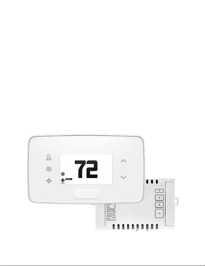
Wireless Energy Management Thermostat
with Built-in Occupancy Sensor and External
HVAC Controller

2
Table of Contents
Introduction .................................................................................................................................................6
SKUs Referenced in this Manual ........................................................................................................... 7
Equipment Nomenclature ...................................................................................................................... 8
Installation Considerations ..................................................................................................................... 9
Network Installation ................................................................................................................................10
Connecting Wireless Receiver .............................................................................................................11
Conguring Online Connection Kit ................................................................................................... 12
HVAC Controller Installation .................................................................................................................13
Introduction ............................................................................................................................................... 13
Using HVAC Controller to Power Wireless Thermostat (Optional) ..........................................14
Using HVAC Controller’s Dry Contacts to Control External Devices ......................................15
Thermostat Installation ..........................................................................................................................16
Mounting Thermostat to Wall..............................................................................................................16
Optional Sensor Installation .................................................................................................................17
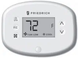
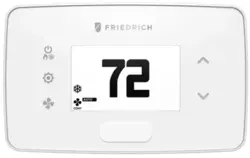
Thermostat Details ...................................................................................................................................18
Thermostat Buttons ................................................................................................................................18
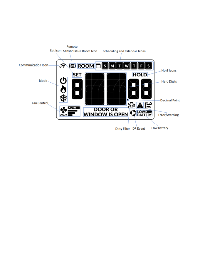
Thermostat Screen ...................................................................................................................................19
Understanding Display Screen Icons ................................................................................................ 19
Thermostat Conguration ....................................................................................................................20
Conguring Thermostat ........................................................................................................................20
Pairing Thermostat with HVAC Controller ....................................................................................... 21
Set MESH ID................................................................................................................................................22
Entering Room Number ........................................................................................................................23
Conguring Equipment Settings .......................................................................................................24
Equipment Codes ....................................................................................................................................24
Conguring Energy Saving Settings ................................................................................................25
Set Thermostat Clock ..............................................................................................................................26

3
Testing Thermostat ..................................................................................................................................27
Thermostat Maintenance ......................................................................................................................28
Replacing Thermostat Batteries ..........................................................................................................28
Thermostat Maintenance ......................................................................................................................29
Activating a Sensor ..................................................................................................................................29
Pairing a Sensor ........................................................................................................................................30
Verifying Sensor Connection Status and Unlinking Sensors ....................................................31
Conguring Functionality of Sensor ................................................................................................. 32
Completing Sensor Setup ..................................................................................................................... 34
Unit Specic Applications .....................................................................................................................35
Connecting HVAC Controller to VRP Unit ........................................................................................ 35
Replacing VRPXEMWRT2 Thermostat with VRPXEMWRT4* Thermostat .............................. 36
Conguring Equipment Settings for VRP ........................................................................................ 37
Conguring Equipment Settings for DSS ........................................................................................ 38
Installing FreshAire® PTAC (Cat 6 to FreshAire® PTAC ) .............................................................. 39
Conguring Equipment Settings for FreshAire® PTAC for digital control ............................ 40
Application Notes.....................................................................................................................................41
Custom Energy Savings Settings ........................................................................................................42
Accessing Custom Energy Savings Settings ................................................................................... 42
Using Thermostat Settings Screens ...................................................................................................43
Scheduler .................................................................................................................................................... 45
Door Lock Integration ............................................................................................................................48
Demand Response ..................................................................................................................................52
Lighting Integration ................................................................................................................................ 53
01 – FAN CONTROL MODE .................................................................................................................... 56
02 – 1
ST
STAGE DIFFERENTIAL - HEAT ................................................................................................ 57
03 – 2
ND
STAGE DIFFERENTIAL - HEAT ...............................................................................................58
04 – 1ST STAGE DIFFERENTIAL - COOL .............................................................................................59
05 – INCIDENTAL OCCUPANCY THRESHOLD ..................................................................................60
Table of Contents

4
06 – NIGHT OCCUPANCY THRESHOLD .............................................................................................61
07 – FORCED 2ND STAGE HEATING ...................................................................................................62
08 – NIGHT OCCUPANCY START ..........................................................................................................63
09 – NIGHT OCCUPANCY END .............................................................................................................64
10 – TEMPERATURE RECOVERY TIME ................................................................................................. 65
11 – RECOVERY TEMPERATURE - HEAT .............................................................................................66
12 – TEMPERATURE SETBACK DELAY ................................................................................................67
13 – MINIMUM SETBACK TEMPERATURE - HEAT ........................................................................... 68
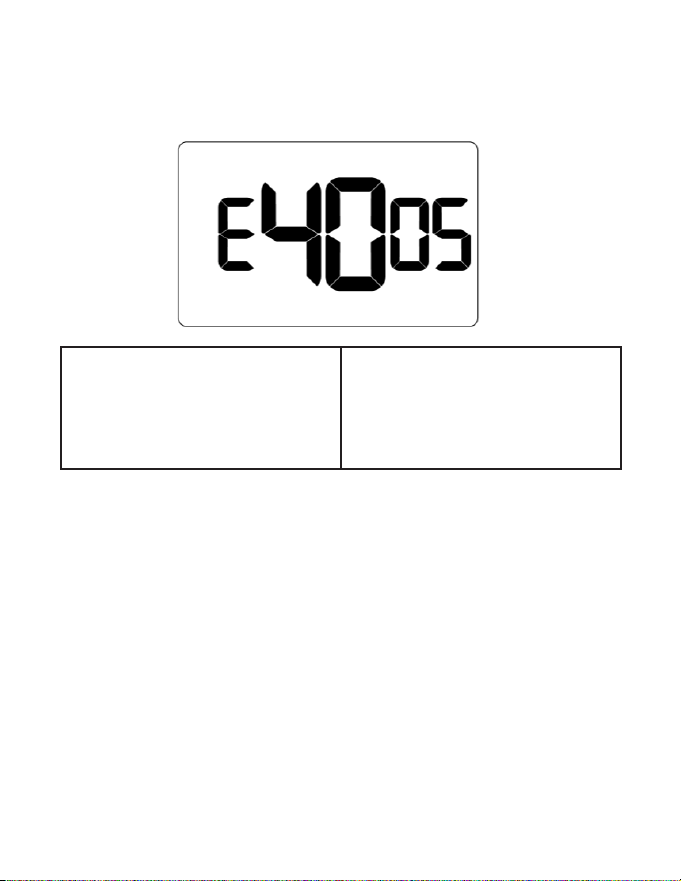
14 – MAXIMUM SETBACK TEMPERATURE ........................................................................................ 69
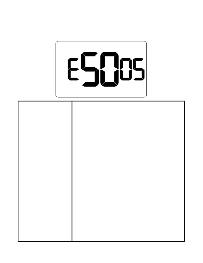
15 – RECOVERY TEMPERATURE - COOL ............................................................................................70
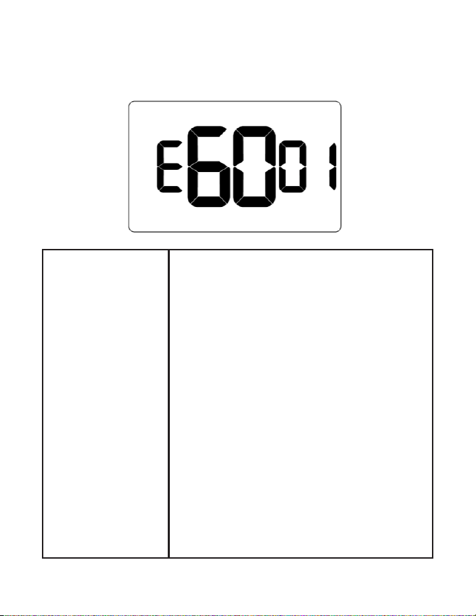
16 – MINIMUM SET POINT .....................................................................................................................71
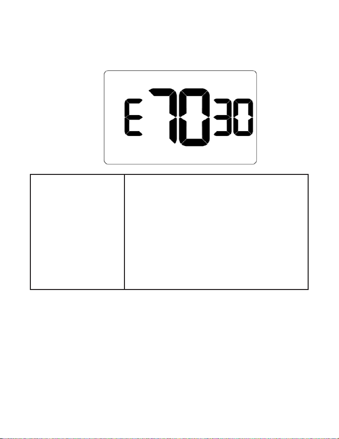
17 – MAXIMUM SET POINT ...................................................................................................................72
18 – TEMPERATURE CONTROL MODE ............................................................................................... 73
19 – AUTO CHANGEOVER SET POINT OFFSET ...............................................................................74
20 – SETBACK SET POINTS ...................................................................................................................75
21– AUTO-RESTORE ................................................................................................................................. 76
22 – PLACEHOLDER SCREEN ................................................................................................................77
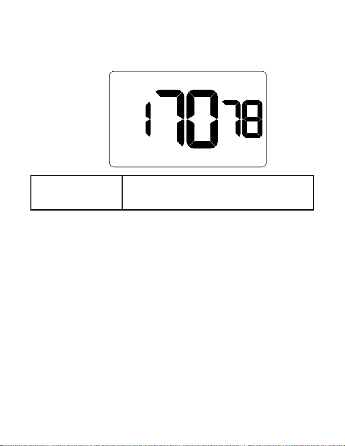
23 – SETPOINT OVERSHOOT ................................................................................................................78
24 – AUTOMATIC HUMIDITY CONTROL ............................................................................................ 79
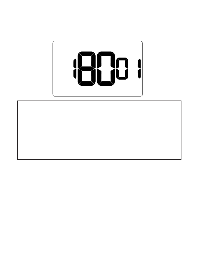
25 – 2ND STAGE COOL DIFFERENTIAL ..............................................................................................80
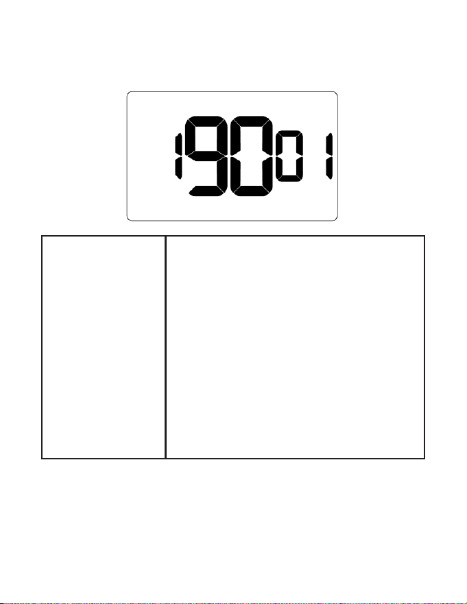
26 – SMART SETBACK .............................................................................................................................81
27 – HUMIDITY CONTROL THRESHOLD ...........................................................................................82
28 – HUMIDITY CUTOFF TEMPERATURE...........................................................................................83
30– ENERGY MANAGEMENT ON/OFF ...............................................................................................85
31– DOOR/WINDOW SHUT OFF DELAY ...........................................................................................86
32– AUTO FAN SPEED 1ST STAGE DIFFERENTIAL ..........................................................................87
33– AUTO FAN SPEED 2ND STAGE DIFFERENTIAL ........................................................................ 88
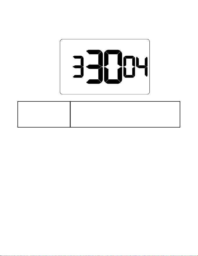
34 – TEMPERATURE CALIBRATION......................................................................................................89
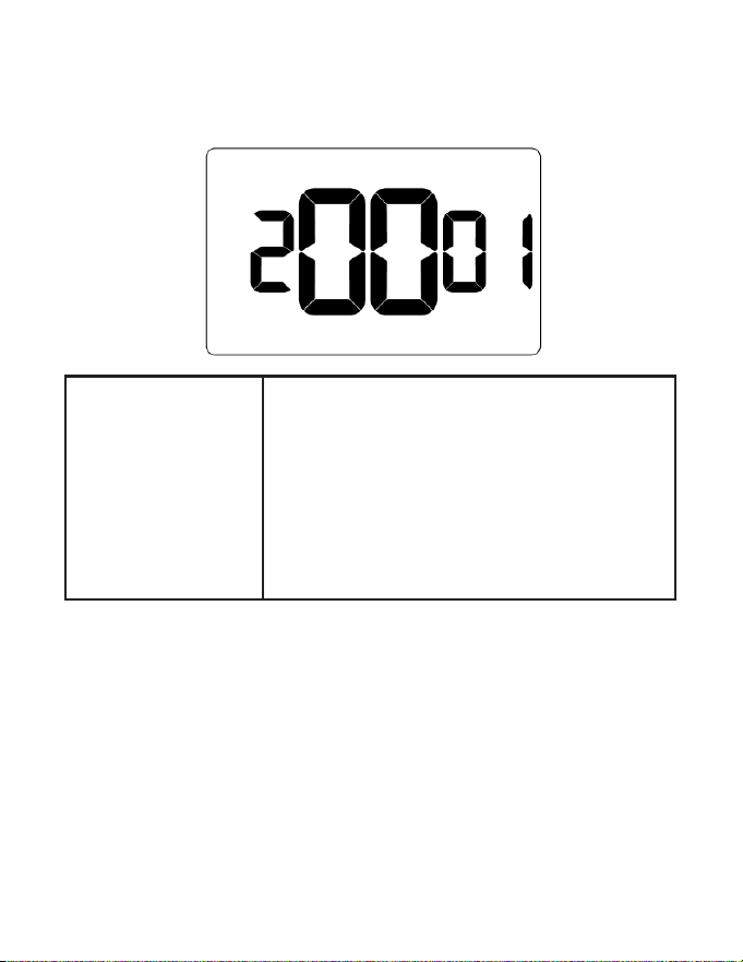
35 – AUTOMODE TYPE............................................................................................................................90
36 – HUMIDITY CONTROL OCCUPIED ROOM .................................................................................91
37 – HEAT EQUIPMENT LOCKOUT ......................................................................................................92
Troubleshooting .......................................................................................................................................93
Restoring Factory Settings....................................................................................................................93
Table of Contents

5
APPENDIX 1 - Energy Saving Presets .................................................................................................94
APPENDIX 2 - Equipment Codes .........................................................................................................96
APPENDIX 3 - Glossary ............................................................................................................................98
Warranty Information .............................................................................................................................99
Technical Specications ...................................................................................................................... 100
Table of Contents

6
The energy management thermostats deliver unprecedented energy savings
without compromising the comfort of occupants.
An integrated occupancy sensor uses a combination of motion and thermal sensing
technologies for accurate occupancy detection. Reliable occupancy detection
allows for energy savings when rooms are unoccupied.
Energy saving presets eliminate the guesswork and make it easy to adjust the
energy saving settings.
Fully congurable energy saving settings allow for customization of the thermostat
settings to t any situation.
Comprehensive conguration options ensure full compatibility with virtually any
existing or emerging HVAC system with up to 4 heat and 2 cool stages.
Built-in wireless mesh-networking enables online management.
Introduction

7
Product Type SKU(s) Description
VRPXEMWRTA4*
Wireless Energy Management Thermostat PIR Oc-
cupancy Detection, VRP & PVH 12V, White
VRPXEMWRTB4*
Wireless Energy Management Thermostat PIR Oc-
cupancy Detection, VRP & PVH 12V, Black
DSSXEMWRTA4*
Wireless Energy Management Thermostat PIR Oc-
cupancy Detection, DSS, White
Network Equipment EMOCT4
EMWRT3/4, DSSXEMWRT3/4, & VRPXEMWRT4*
Online Connection Kit for Wireless Network Access**
Network Access EMRAF4 Wireless Network Access Fee
Remote Sensors
EMRWOS4 Secondary Wireless Occupancy Sensor
EMRTS4 Secondary Wireless Temperature Sensor
EMRDS4 Wireless Door/Window Switch
Wall Plates
EMCWPA4 Thermostat Wall Plate White
EMCWPB4 Thermostat Wall Plate Black
HVAC Controller EMCC6R4 Stand-alone Wireless Control Card
Secondary Radio EMZBU4 Embedded Zigbee/BLE Chip
*‘R’ and ‘U’ SKUs also available.
**Online Connection Kit is required to enable Wireless Web Based Remote Management. One
(1) Online Connection Kit can accommodate up to 1,024 Networked Thermostats depending on
property layout and conguration.
Introduction
SKUs Referenced in this Manual
This user guide includes instructions on how to install each of the following
compatible SKUs.
8
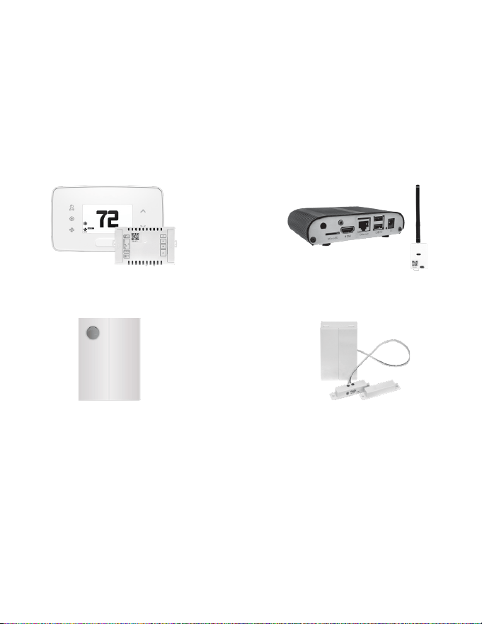
Equipment Nomenclature
Before you begin installing this equipment, we recommend you familiarize yourself
with the various components that may be included in your shipment.
EM Thermostat & HVAC Controller
Occupancy Sensor
Door/Window Sensor
Online Connection Kit
Introduction

THE THERMOSTAT’S OCCUPANCY SENSOR SHOULD FACE THE BED
AREA OF THE ROOM OR THE AREA WHERE THE OCCUPANT WILL
SPEND THE MOST TIME.
THE THERMOSTAT MUST NOT BE INSTALLED IN THE VICINITY OF
LARGE METAL STRUCTURES OR SURFACES INCLUDING METAL AIR
DUCTING THAT MAY BE IN THE WALL. LARGE METAL STRUCTURES
BETWEEN THE THERMOSTAT AND CONTROL CARD AND/OR THE
ONLINE CONNECTION KIT SUCH AS METAL CABINETS OR DOORS/
ELEVATOR SHAFTS SIGNIFICANTLY REDUCE THE RANGE OF THE
WIRELESS SIGNAL AS THEY DEFLECT THE SIGNAL AND THEY DON’T
ALLOW IT TO PASS THROUGH THEM, THUS REDUCING THE SIGNAL
STRENGTH BETWEEN THE DEVICES MENTIONED.
DO NOT INSTALL THE THERMOSTAT NEAR WINDOWS OR DOOR
VENTS, ON AN EXTERIOR WALL, ABOVE OR BELOW SUPPLY VENTS, OR
OTHER LESS OCCUPIED AREAS.
9
Installation Considerations
Selecting the appropriate installation location of the thermostat and any accessories
is crucial to the proper operation of your energy management system. The following
guidelines should be adhered to in all cases;
Introduction

THE ANTENNA(S) USED FOR THIS TRANSMITTER MUST NOT BE
CO-LOCATED OR OPERATING IN CONJUNCTION WITH ANY OTHER
ANTENNA OR TRANSMITTER AND MUST BE INSTALLED TO PROVIDE A
SEPARATION DISTANCE OF AT LEAST 20CM FROM ALL PERSONS.
10
NOTICE
TO ENABLE NETWORKING CAPABILITIES OF THE THERMOSTAT,
REFER TO THE “NETWORK INSTALLATION” SECTION OF THIS
MANUAL.
BEFORE STARTING THE INSTALLATION OF THE NETWORKED
THERMOSTATS, ENSURE THE ONLINE CONNECTION KIT IS
CONNECTED TO THE INTERNET.
CONFIRM THE ONLINE CONNECTION KIT IS COMMUNICATING
PROPERLY WITH THE CLOUD SERVICE BY CALLING TECHNICAL
SUPPORT AT 1 877 318 1823.
Network Installation
THE ANTENNA MODULE MUST BE INSTALLED WITHIN 100FT FROM THE
FIRST 2 TO 3 THERMOSTATS, AND MUST NOT BE INSTALLED NEAR LARGE
METAL STRUCTURES OR SURFACES.
TO PREVENT POWER RELATED ISSUES, PLUG THE SERVER INTO A UPS
(UNINTERRUPTED POWER SUPPLY) UNIT.
11
Network Installation
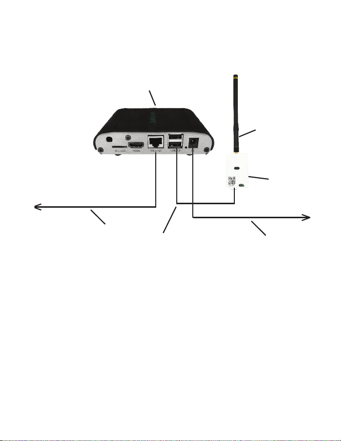
Connecting Wireless Receiver
1. Screw Antenna (1) onto Wireless Receiver (2)
2. Connect Wireless Receiver (2) to Server (4) using supplied USB cable (3)
3. Ax Wireless Receiver (2) to wall with double sided adhesive tape
4. Orient Antenna (1) to point upwards to the closest room in which a thermostat
will be installed
5. Connect Server (4) to the LAN port with the supplied RJ-45 cable (5)
6. Plug Server (4) into electrical outlet with power cord (6)
To Internet Router/Switch
To Power supply
1
2
4
5
6
3

12
Network Installation
Conguring Online Connection Kit
1. Ensure Online Connection Kit is receiving an IP from a DHCP server.
NOTE: it is not recommended to use a public IP
2. Ensure MAC address is properly Whitelisted if it needs to bypass a login
(splash) page to reach the internet
NOTE: MAC address is printed on a white sticker on bottom of Online
Connection Kit.
3. If behind a rewall, OUTBOUND ports 22, 80, and 443 must be allowed for the
Online Connection Kit. No INBOUND ports are required for this device unless
specic options are requested.
For any technical support on Networking and Connections, please call 877-
318-1823
13
HVAC Controller Installation
Introduction
HVAC Controllers enable wireless thermostat control of most HVAC units. The HVAC
Controller has relay 24VAC outputs, analog 0-10VDC outputs, and digital data
(RS485) outputs to allow for control of virtually any HVAC unit.
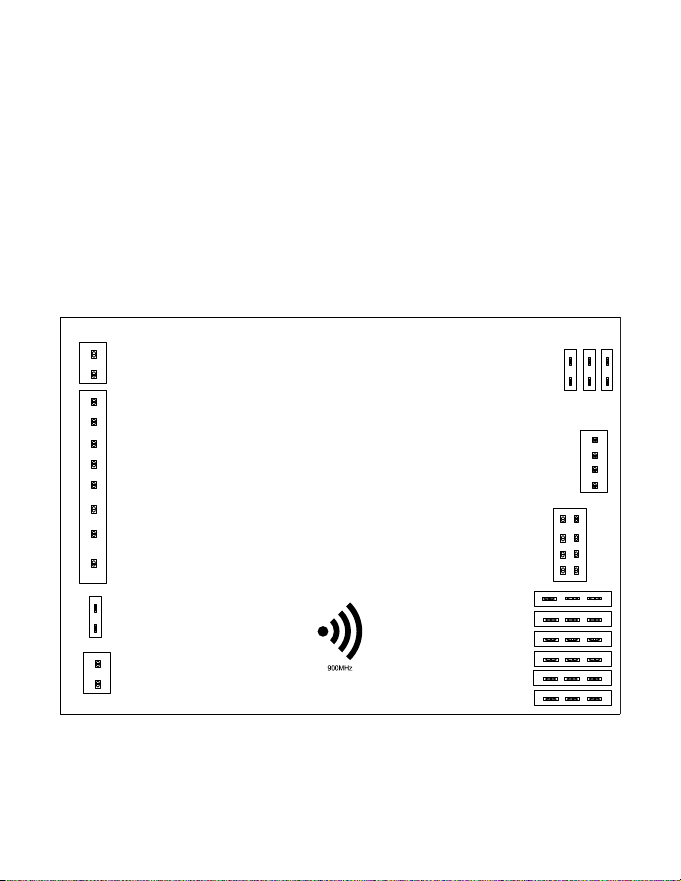
The illustration below indicates the various ports available on the HVAC Controller.
Refer to the appropriate page in this manual for wiring instructions for your specic
HVAC unit.
VRF
HVAC CONTROLLER
C
R
W
Y
OB
AUX2
GL
GH
12V
GND
J10
OCCUPANCY OUT
JUMPER
3 6
2 5
1 4
J5
12V
RX
J4
J6
J2
J11
J3
J9
ANALOG IN / OUT
DAC
OEM (MIE/LG)
12 V OUT
TX
GND
O2 I2
O1 I1
GND GND
O0 I0
18 17 16
15 14 13
12 11 10
98 7
65 4
32 1
RS485
AUX1 OUT
AUX1 IN

14
HVAC Controller Installation
Using HVAC Controller to Power Wireless Thermostat (Optional)
The J11 port on the HVAC Controller may be used to supply 12VDC power to a
wireless thermostat, if desired.
Use the supplied wire harness to connect the J11 port to the back of the wireless
thermostat
12VDC Output
(J11 Port)
12VDC GND
15
HVAC Controller Installation
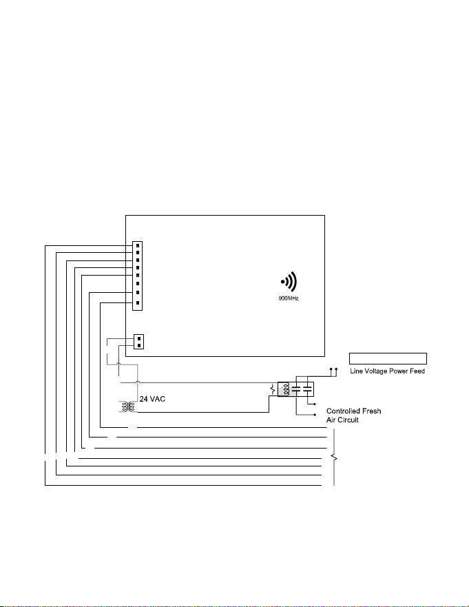
Using HVAC Controller’s Dry Contacts to Control External Devices
The J9 port on HVAC Controller can be used as a dry contact for control of external
devices such as lighting relays and dampers. Refer to application notes for more
information.
1. Connect jumper on J10 to create a wet contact supplying power from R&C.
R1
From 110VACBreaker
FCU/VTAC/PTAC
Unit ControlBoard
(This will depend on
the HVAC)
BK
RD
WH
YE
BR
BK
PU
GR
OR
HVAC
CONTROLLER
C
R
W
Y
OB
AUX2
GL
GH
OUT
J9
IN
OCCUPANCY
OUT
J3
XFMR 01

16
Mounting Thermostat to Wall
1. Select appropriate installation location for thermostat per below:
2. If using a wall plate, place it over hole in wall left from previous thermostat and
mark two locations for drilling holes
3. Place thermostat on wall in installation location and mark location for drilling
holes for two mounting screws
4. Drill two 3/16” holes in wall and insert two wall anchors
5. Use two screws to securely mount thermostat to wall
6. Insert two AA alkaline batteries in thermostat. The thermostat can also be
powered with 12VDC or 24VAC
Thermostat Installation
THE THERMOSTAT’S OCCUPANCY SENSOR SHOULD FACE THE BED
AREA OF THE ROOM OR AREA WHERE OCCUPANT WILL SPEND THE
MOST TIME.
THE THERMOSTAT MUST NOT BE INSTALLED IN THE VICINITY OF
LARGE METAL STRUCTURES OR SURFACES INCLUDING METAL AIR
DUCTING. DO NOT INSTALL THERMOSTAT NEAR WINDOWS OR
DOORS WHICH MAY ALLOW A DRAFT, ON AN EXTERIOR WALL, ABOVE
OR BELOW SUPPLY VENTS, AND OTHER LESS OCCUPIED AREAS.
DO NOT OVER TIGHTEN THE BACK PLATE TO THE WALL. FOR UNEVEN
SURFACES INSTALL A WALL PLATE.

17
1. Select appropriate installation location
2. With faceplate removed, place sensor on wall in installation location and mark
location for drilling holes for two mounting screws
3. Drill two 3/16” holes in wall and insert two wall anchors
4. Use two screws to securely mount sensor to the wall
5. Insert one AAA alkaline battery into compartment (wireless sensors only)
OCCUPANCY SENSORS SHOULD FACE THE DESIRED OCCUPANCY
DETECTION AREA.
Optional Sensor Installation
18
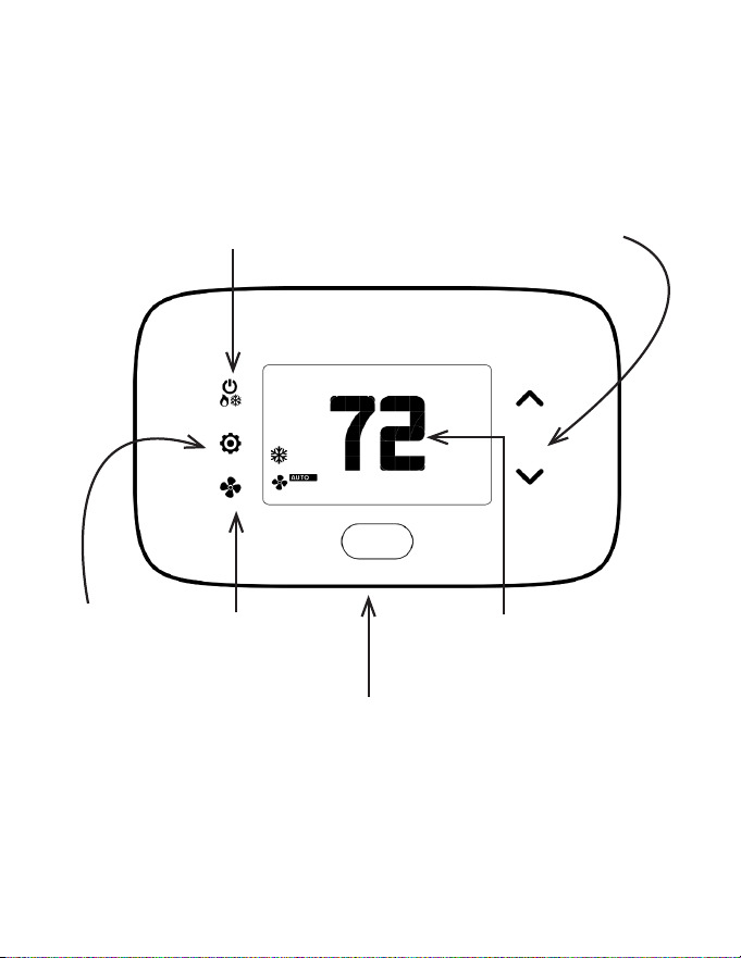
Thermostat Details
Thermostat Buttons
UP | DOWN
Increase | Decrease values
SETTINGS
Change F | C
Activate Scheduler
SYSTEM MODE
Cycle between
AUTO | HEAT | COOL | OFF
FAN MODE
OCCUPANCY SENSOR
ROOM TEMPERATURE/
SETPOINT
*In AUTO Mode, cycle between ON | OFF. In MANUAL mode, Cycle
between OFF | HEAT | COOL
19
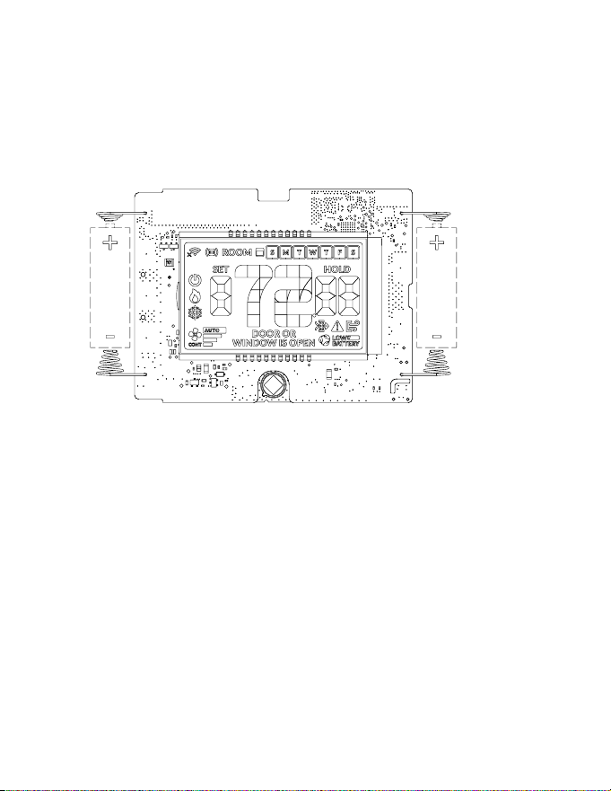
Thermostat Screen
Understanding Display Screen Icons
20
Thermostat Conguration
Conguring Thermostat
Prerequisites: During installation training with your support agent you will be provided
with: Mesh ID (if Networked, provided by Technical Support), Room Number, Time, and
Equipment Code. For VRP & PVH 12V insert one jumper into function selection pins 1
and 2 and another jumper in pins 4 and 5 at J5 on the control card.
To start with the conguration process, remove faceplate and insert 2 AA batteries.
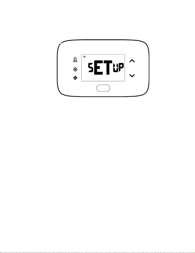
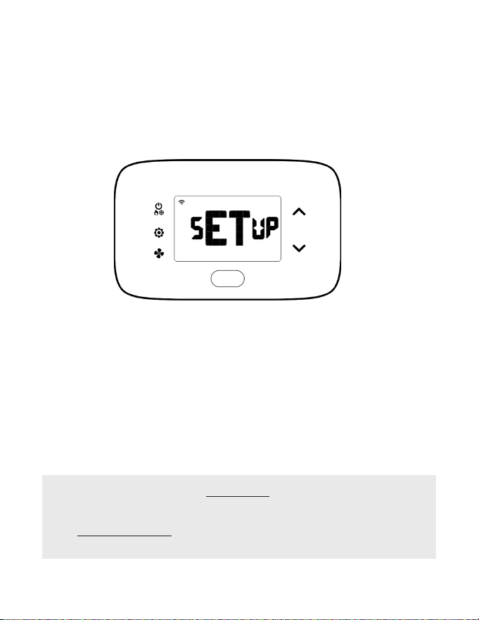
NOTE: Press and hold FAN and SYSTEM MODE buttons.
Turn on thermostat and HVAC unit to activate setup screen (shown above) and
complete the below settings shown the following pages:
1. Pair thermostat with HVAC Controller
2. Set MESH ID (only for Networked Systems)
3. Enter room number
4. Enter equipment code
5. Congure energy saving settings
6. Set thermostat clock
7. Enable/Disable Scheduler
NOTE: If the thermostat does not display SETUP when rst powering the device,
then it has already been paired to an HVAC Controller. To exit conguration menu at
any time, press the SYSTEM MODE button.
21
• If the HVAC controller ID displayed does not match, press the down button
to see what other controllers are trying to connect with the thermostat. Keep
pressing until you identify the matching controller number.
• If no controller ID is found, FAIL will appear on the screen. Press the ON | OFF
button to get back to the initial setup screen and repeat procedure.
Thermostat Conguration
Pairing Thermostat with HVAC Controller
Each wireless thermostat must be paired with an individual HVAC Controller during
installation. The thermostat will search for the closest HVAC Controller and display
the unique HVAC Controller ID. The HVAC Controller ID is located on the case of the
HVAC Controller. Only install one room at a time.
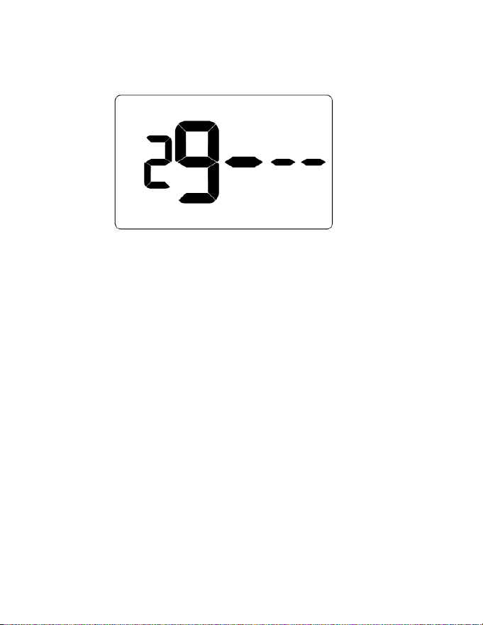
Press SETTINGS button. The thermostat will initiate a thirty (30) second countdown
with a blinking connectivity icon before displaying the closest HVAC Controller ID
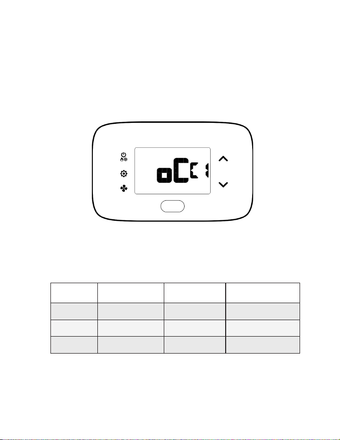
1. Verify HVAC controller ID found by thermostat matches the ID’s last 5 digits
listed on HVAC controller in the same room
2. Press SETTINGS button to pair thermostat with HVAC Controller displayed
on the screen. The screen will display SUCC when the HVAC Controller has
been paired successfully. If the HVAC Controller ID displayed on the screen is
incorrect, press the FAN button to reject it and follow the bolded section below
3. If pairing is successful, wait 5-10 seconds and press SETTINGS button to
advance to the Mesh ID conguration page

22
Thermostat Conguration
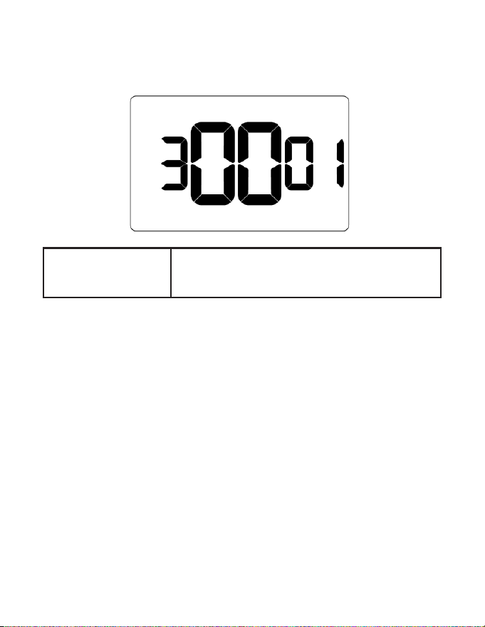
Set MESH ID (FOR NETWORKED SYSTEMS ONLY)
For networked installations, a unique MESH ID is associated to each Online
Connection Kit and is provided by your technical support agent during the
installation training (also be found labeled on device).
For properties using a single Online Connection Kit, each thermostat may be linked
to MESH ID 0001. For properties requiring multiple Online Connection Kits, each
thermostat should be linked to the MESH ID of the closest Online Connection Kit.
1. Press UP | DOWN buttons to increase or decrease value
2. Press FAN button to advance to next digit
3. Press SETTINGS button to advance to next step
23
Thermostat Conguration
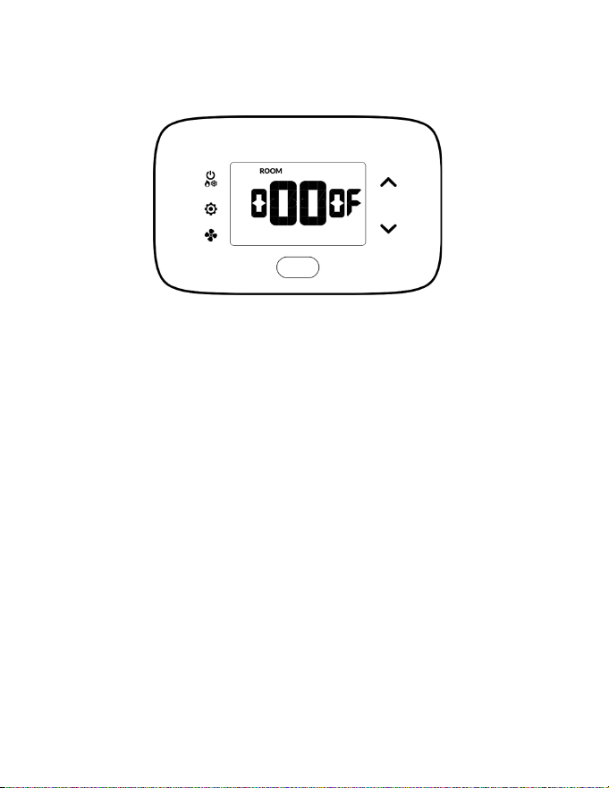
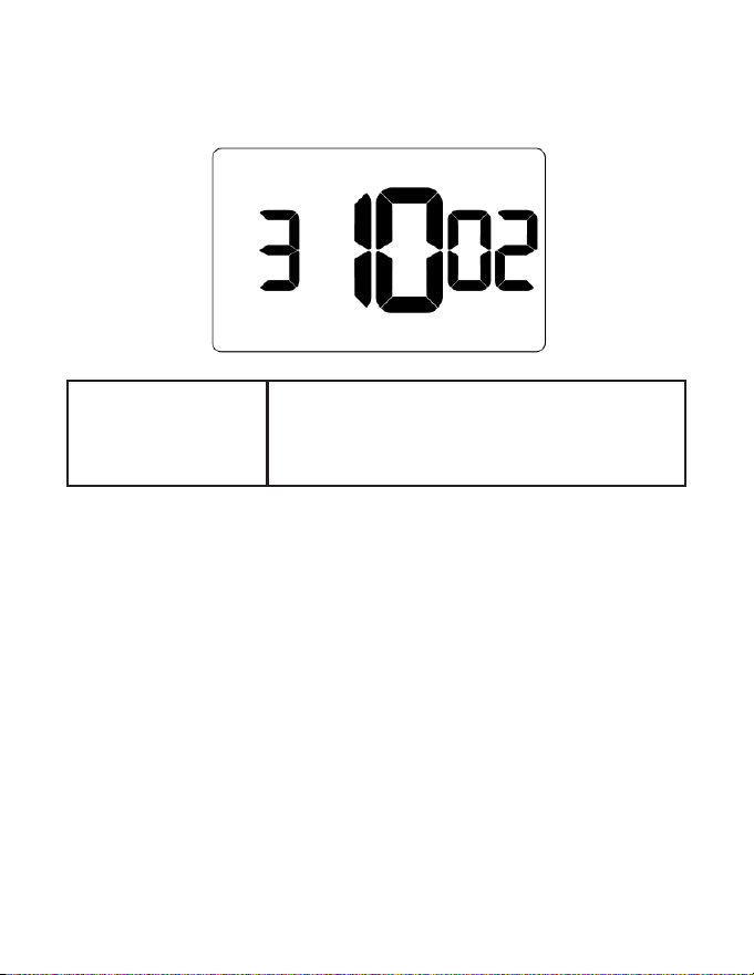
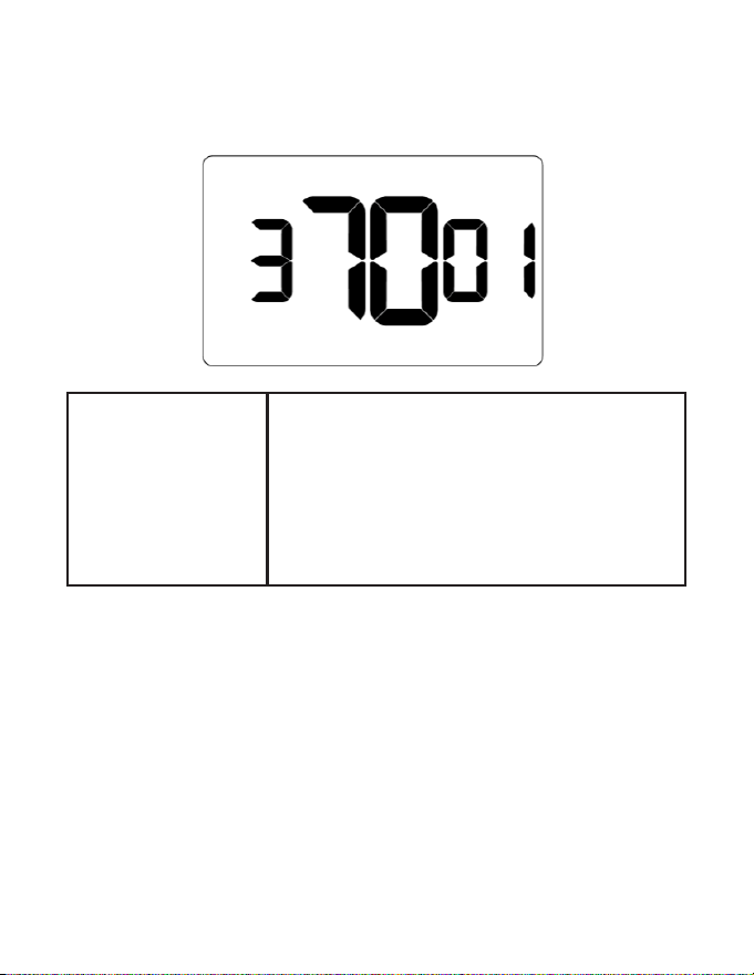
Entering Room Number
Enter room number by changing characters on screen. Available characters include
digits 0-9 and letters A-F. To distinguish between two or more thermostats in the same
unit, enter as follows:
Thermostat 1: 00100
Thermostat 2: 0100A
1. Press UP | DOWN buttons to increase or decrease the value
2. Press FAN button to advance to the next digit
3. Press SETTINGS button to advance to next menu
Entering room number correctly is crucial for proper operation of thermostats with online
management/networking.

24
Wall Controller Conguration
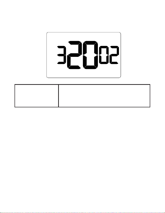
Equipment Codes
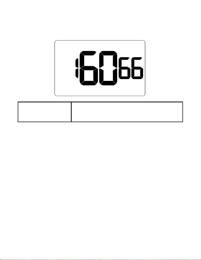
Enter equipment code by changing digits on the screen.
* PTAC PVH models can connect either AC or DC control wiring:
• PVH that nishes in -A connects to 24 V and runs with equipment code 1012.
• PVH that nishes in -B might connect to 12 V and 24 V depending on the
wiring connection.
• If 12 V connected, runs on equipment code 6603.
• If 24 V is connected, runs on equipment code 1012.
For more information on installation of the units see below sections:
• VRP unit-specic installation (page 35)
• DSS unit-specic installation (page 39)
• FreshAire PTAC unit-specic installation (page 39)
Model Description Equipment Code
VRP/FreshAire 12 V Control*
6603
DSS 6643
25
Thermostat Conguration
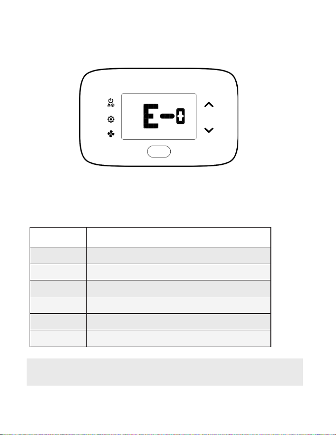
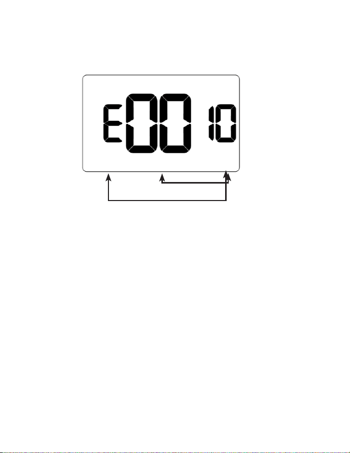
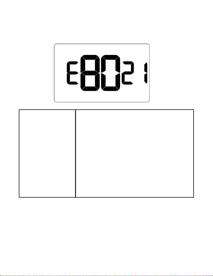
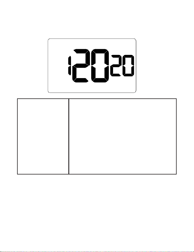
Conguring Energy Saving Settings
1. Press UP | DOWN buttons to increase or decrease energy savings preset
2. Press SETTINGS button to advance to next menu
*default setting
Preset Energy Savings Presets
E-0* Energy Savings O - No Temperature Setback
E-1 Lowest Energy Savings
E-2 Lower Energy Savings
E-3 Standard Energy Savings
E-4 Higher Energy Savings
E-5 Highest Energy Savings
Please refer to Appendix 1 for more details on these presets
26
Thermostat Conguration
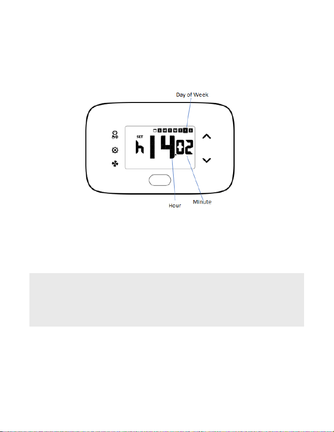
Set Thermostat Clock
Set thermostat clock to current time in 24h format.
1. Press UP | DOWN buttons to increase or decrease digits
2. Press FAN button to advance to next digit
3. Press SETTINGS button once to go to current room temperature screen.
4. Setup is now complete
SETTING CORRECT TIME IS CRUCIAL FOR PROPER OPERATION OF
THERMOSTAT. TIME UPDATES AUTOMATICALLY IF CONNECTED TO
ONLINE CONNECTION KIT.

Thermostat Conguration
27
Testing Thermostat
Following thermostat conguration, test if the thermostat is controlling the HVAC
unit.
1. Ensure thermostat is powered and faceplate is axed
2. Press DOWN button to change temperature set point below current room
temperature to conrm thermostat initiates cooling
3. Press UP button to change temperature set point above current room
temperature to conrm thermostat initiates heating
4. Change fan speed by touching FAN button to verify thermostat is controlling
fan speed

28
Replacing Thermostat Batteries
The low battery indicator is displayed on thermostat screen when necessary to
replace batteries.
Under normal operating conditions, new brand-name alkaline batteries last for
approximately 18 months. Replace batteries every 16 months to ensure continuous
thermostat operation.
1. Remove thermostat cover
2. Replace two AA alkaline batteries
3. Re-ax thermostat cover
4. Press SYSTEM MODE button to start thermostat.
NOTE: Thermostat maintains all previous conguration settings in non-
volatile memory.
Thermostat Maintenance

Thermostat Maintenance
29
Activating a Sensor
1. Remove the faceplate from the sensor to be paired
2. Insert two AAA alkaline batteries into each sensor
3. Press button inside sensor to make sensor discoverable
4. Navigate to “Pairing a Sensor” on page 30
NOTE: The sensor(s) will remain discoverable for ve (5) minutes after
pressing the button inside the device. If the pairing process has not been
completed within ve (5) minutes, push button inside sensor again.
Pairing a Sensor
Ensure thermostat and HVAC unit are powered and thermostat faceplate is removed.
The thermostat conguration screens have a 30-second time-out. If no action is
taken within this time, the thermostat exits conguration settings.
1. Press and hold SYSTEM MODE and FAN buttons on thermostat to access
Mesh ID screen
2. Press and hold SYSTEM MODE and FAN buttons again until type appears
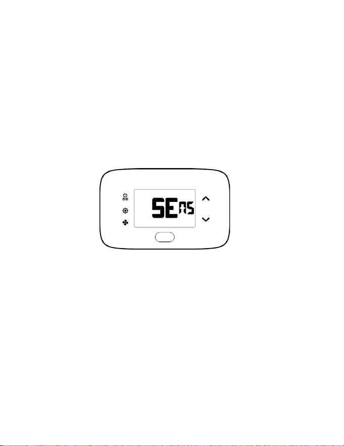
3. Press SETTINGS button until SENS appears
4. Press FAN button on thermostat to initiate pairing of a new sensor ,or,
press SETTINGS to manage existing sensors. This will initiate a 10 second
countdown and display the last 5 digits of the sensor ID(s) discovered during
the pairing procedure.
5. Use UP | DOWN buttons to toggle between discovered sensors
6. Ensure unique device ID displayed on screen matches unique device ID of
sensor to congure
7. Press SETTINGS button when Add appears
8. Press SETTINGS button to pair selected sensor to HVAC Controller
9. Verify SUcc shows on screen
NOTE: If pairing fails, press ON | OFF button to exit and perform procedure again.
30
Conguring & Managing Accessories
31
Conguring & Managing Accessories
Verifying Sensor Connection Status and Unlinking Sensors
NOTE: Thermostat and HVAC unit must be powered
1. Remove faceplate from thermostat
2. Press and hold SYSTEM MODE and FAN buttons until MESH ID appears on
the screen
3. Press and hold SYSTEM MODE and FAN buttons again until type appears
on screen
4. Press SETTINGS button again until SENS appears on the screen
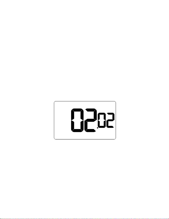
5. Press SETTINGS button. The Thermostat will initiate a 10 second countdown
before displaying the number of linked sensors currently communicating with
the thermostat (e.g. 02.02 means 2 out of 2 linked sensors is communicating
with thermostat
6. Press SETTINGS button to display the rst linked sensor and UP | DOWN
buttons to cycle through linked sensors
7. After selecting sensor to be unlinked, press and hold CONFIG button. The
thermostat will initiate a 10 second countdown before displaying the total
number of linked sensors
8. Press SYSTEM MODE button to exit this conguration menu
9. Press button on the sensor for 3 seconds until a yellow light turns on. The
sensor is now reset and can be paired to the thermostat again if necessary.
32
Conguring & Managing Accessories
Conguring Functionality of Sensor
The thermostat allows the user to choose the functionality of a sensor. Use the table
below to congure the desired functionality. For example, if sensor is intended to be
used as Occupancy Sensor, OCC value must be set to 1.
NOTE: OCC default setting = 0
1. Press SETTINGS button to select sensor
2. Press SETTINGS button to move to Occupancy Sensor conguration screen
OCC and use the UP | DOWN buttons to increase or decrease digit according
to below table
Trailing Digit
Value
OCC cx
(Occupancy Sensor)
dsx
(Door Switch)
rtx
(Temperature Sensor)
0* Disabled Disabled Disabled
1 Enabled Normally Closed Master
2 Normally Open Average
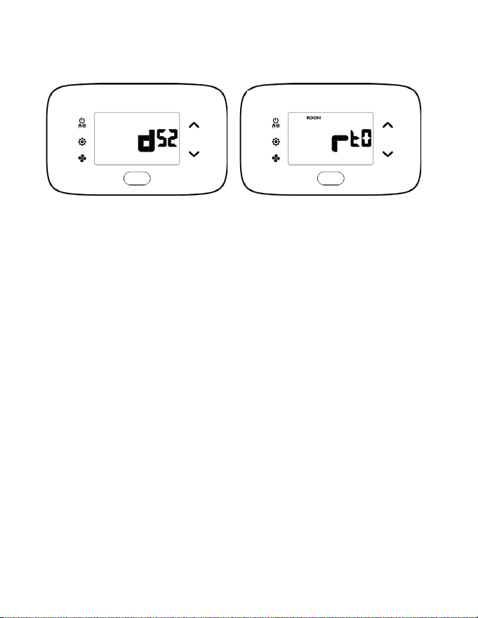
33
Conguring & Managing Accessories
3. Press SETTINGS button to congure Door Switch functionality (dsx). Door switch
functionality should be set to Normally Open (NO) or Normally Closed (NC)
depending on reed switch
4. Press SETTINGS button to congure Temperature Sensor functionality (rtx)
5. Press SETTINGS button to move to ADD screen
6. Press FAN button to nalize pairing
34
Conguring & Managing Accessories
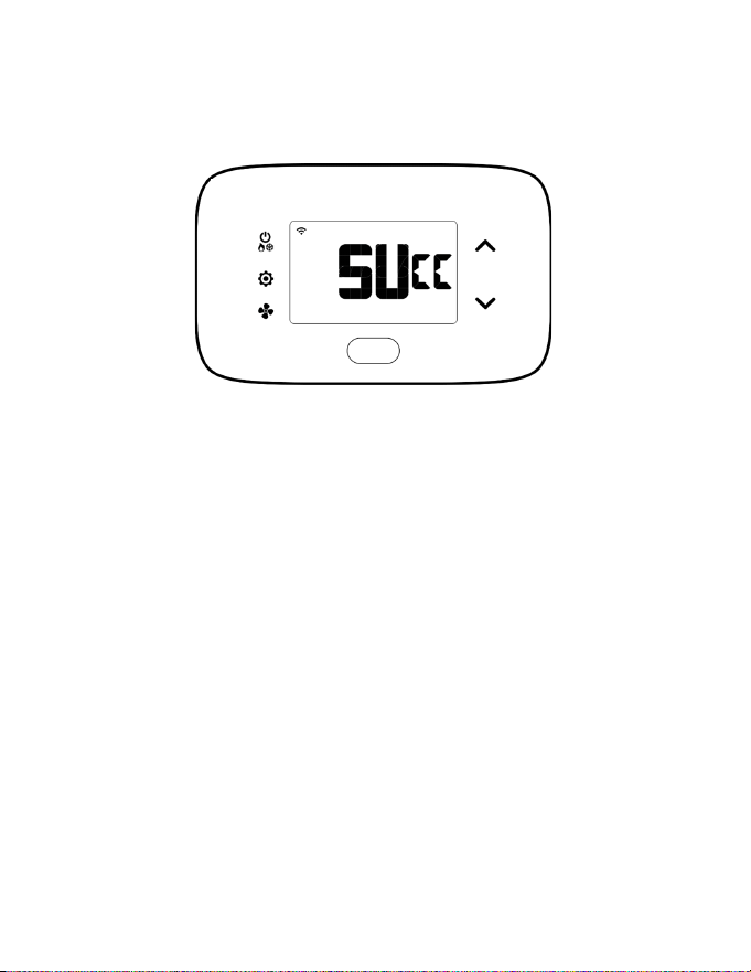
Completing Sensor Setup
The thermostat will countdown from thirty (30) seconds. If the sensor has
successfully paired, the thermostat will display SUCC. If the sensor did not pair
successfully, the display will read FAIL, and the procedure must be repeated.
1. Press SYSTEM MODE button to exit sensor setup screen
2. Repeat Sensor setup as many times as necessary
35
Unit Specic Applications
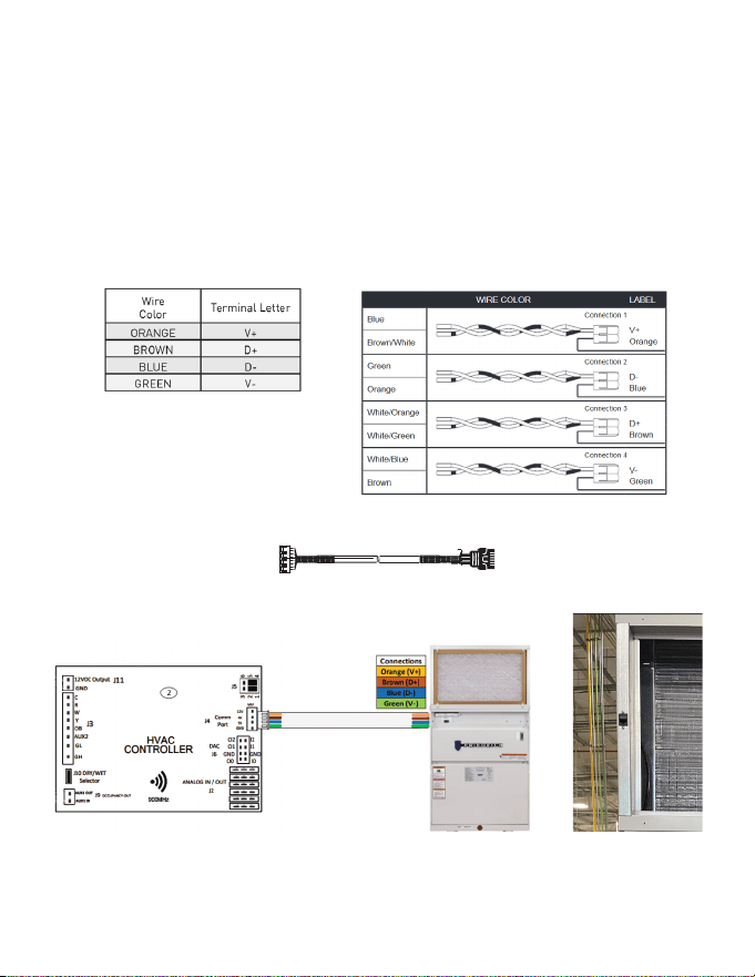
Connecting HVAC Controller to VRP Unit
1. Connect harness to HVAC Controller
2. Connect other end of harness into the RJ45 socket on the VRP
3. Insert the provided jumpers into pin termials 1-2 and 4-5 of the J5 port
4. Ensure that that the control card NOT installed inside the VRP chassis
HVAC Controller Side VRP Side
36
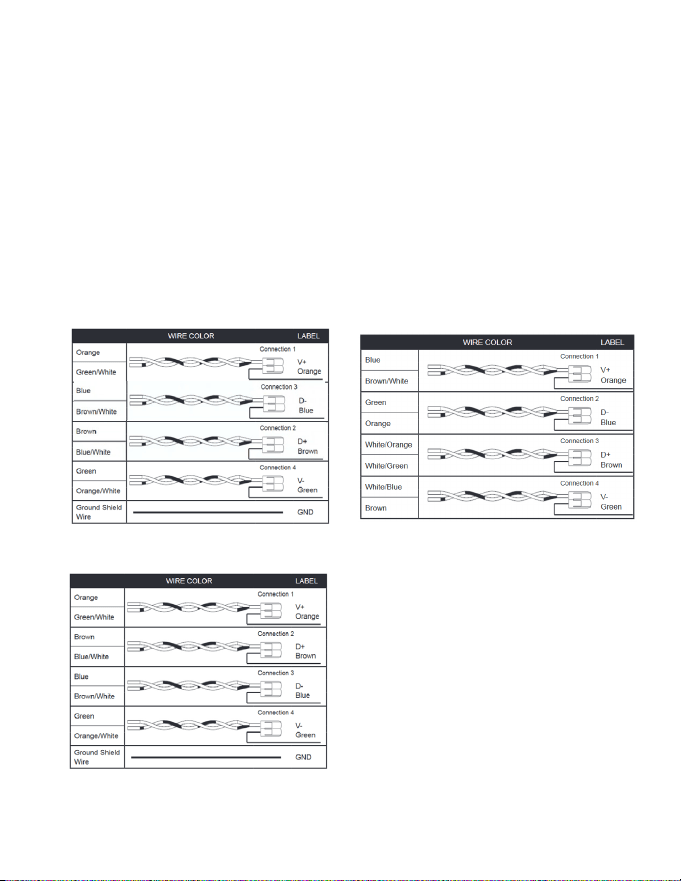
Replacing VRPXEMWRT2 Thermostat with VRPXEMWRT4* Thermostat (PVH Models
only)
1. Color coordination/coding is the same between the two devices.
2. D+ & D- are reversed between the VRPXEMWRT2 and VRPXEMWRT4*.
3. Wires for D+ and D- can be reversed at the control card OR at the VRP unit.
VRPXEMWRT2 VRPXEMWRT4*
OR

37
Unit Specic Applications
Conguring Equipment Settings for VRP
Enter equipment code 6603 by changing digits on screen.
1. Press FAN button to advance to the next equipment setting
2. Press UP | DOWN buttons to increase or decrease value to 6603
3. Press SETTINGS button to advance to next menu
4. After entering equipment code, the thermostat requires the source of the
temperature reading. Temperature can be sensed by the thermostat (TS) or by
conditioning unit (AC) if a conditioning unit supports the option of reading
temperature.
5. Press UP | DOWN buttons to select TS (preferable over AC).
38
Unit Specic Applications
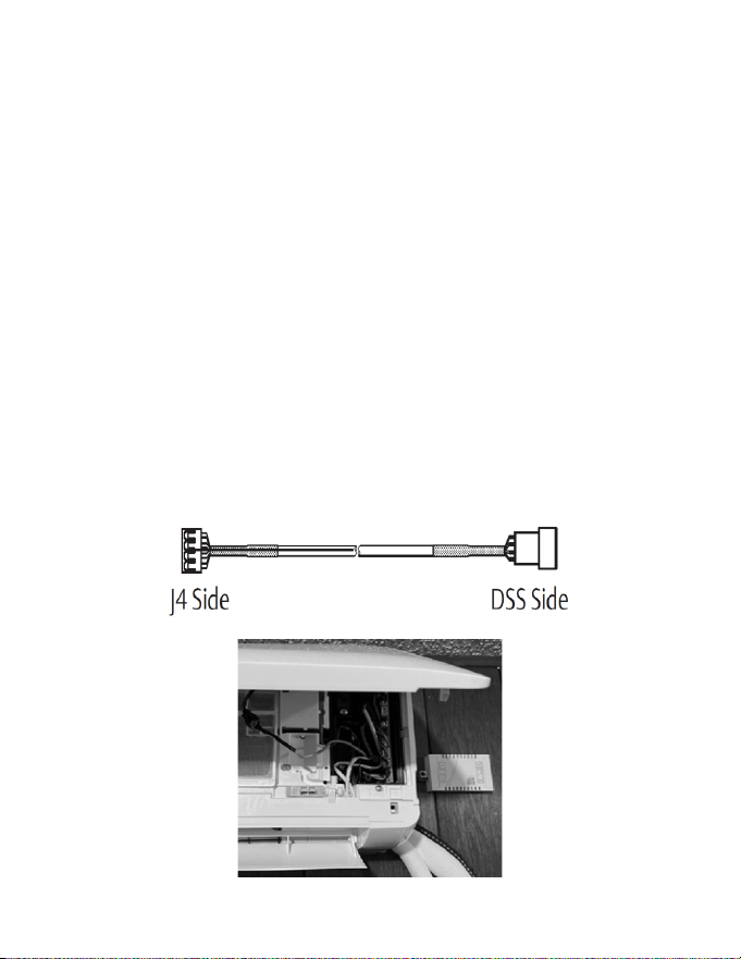
Conguring Equipment Settings for DSS
Enter equipment code 6643 by changing digits on screen.
1. Mount the HVAC controller next to the DSS head.
2. Disconnect the WiFi module in the DSS Pro/Premier wall-mount or cassette
and connect to control card (J4 port) using the other end of the wire harness
provided
3. Press FAN button to advance to the next equipment setting
4. Press UP | DOWN buttons to increase or decrease value to 6603
5. Press SETTINGS button to advance to next menu
6. After entering equipment code, the thermostat requires the source of the
temperature reading. Temperature can be sensed by the thermostat (TS) or
by conditioning unit (AC) if a conditioning unit supports the option of reading
temperature.
7. Press UP | DOWN buttons to select AC for DSS.
39
Unit Specic Applications
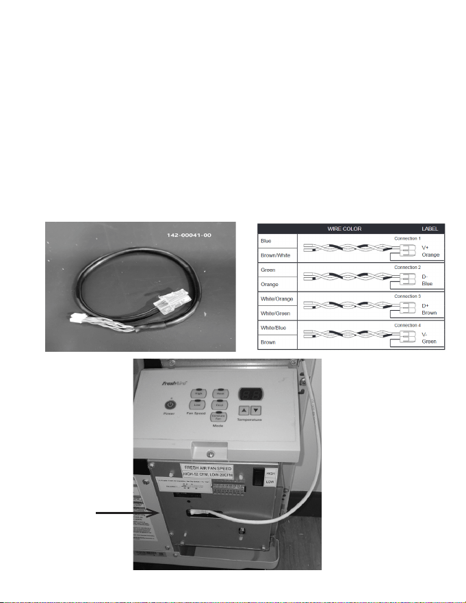
Installing FreshAire® PTAC (Cat 6 to FreshAire® PTAC )
NOTE: FreshAire® PTAC models with a SKU ending in ‘A’ are only compatible with
24V. FreshAire® PTAC models with a SKU ending in ‘B’ and above are compatible
with VRPXEMWRT* thermostat.
1. Connect one end of Cat6/Cat5 wire to FreshAire® PTAC using RJ45 port on PTAC
unit using harness 142-00041-00.
2. Insert the provided jumpers into pin termials 1-2 and 4-5 of the J5 port
RJ45 PORT

40
Unit Specic Applications
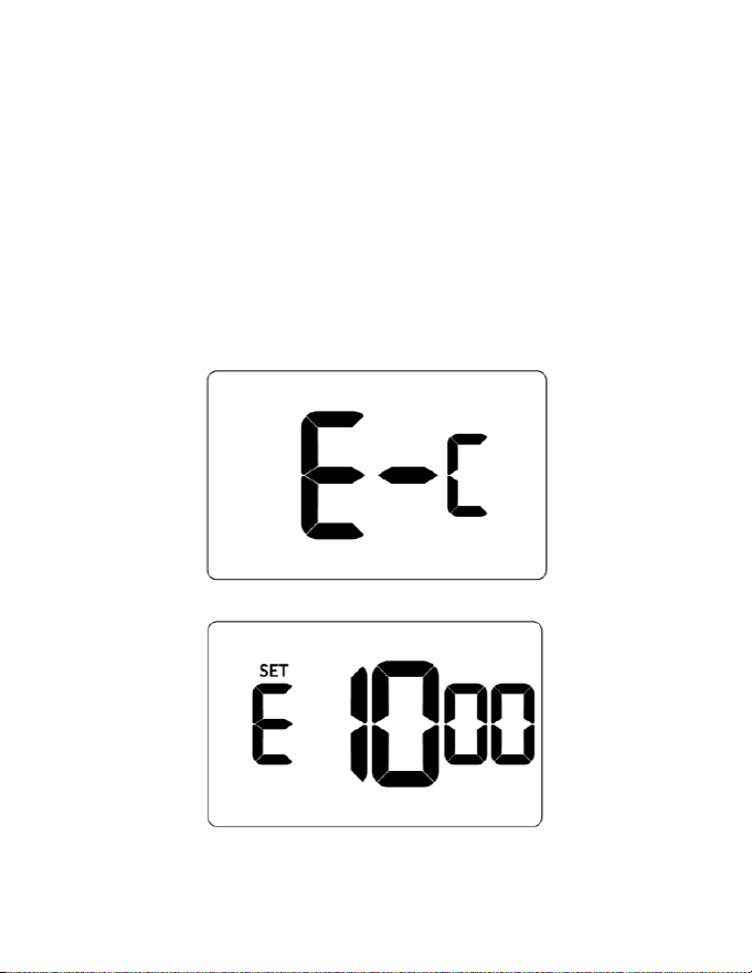
Conguring Equipment Settings for FreshAire® PTAC for digital control
Enter equipment code 6613 by changing digits on screen.
1. Press FAN button to advance to the next equipment setting
2. Press UP | DOWN buttons to increase or decrease value to 6613
3. Press SETTINGS button to advance to next menu
4. After entering equipment code, the thermostat requires the source of the
temperature reading. Temperature can be sensed by the thermostat (TS) or by
conditioning unit (AC) if a conditioning unit supports the option of reading
temperature.
5. Press UP | DOWN buttons to select TS (preferable over AC).

41
Application Notes
A comprehensive list of published application notes can be found at
www.verdant.co/resources/application-notes.
Applications include (among others):
1. Energy Savings Settings
2. Scheduler
3. Door-lock ZigBee Integrated Solution
4. Demand Response
5. Hilton PEP
6. IHG Studio
7. Occupancy Based Lighting Control
8. Advanced Lighting Application: ZigBee Controlled Switch and socket from
LEVITON
42
Custom Energy Savings Settings
If you do not want to use one of the energy saving presets detailed in Appendix 1,
you can enter the custom energy savings settings.
Accessing Custom Energy Savings Settings
1. Ensure thermostat is powered and faceplate removed
2. Press and hold CONFIG button to access Mesh ID screen
3. Press SETTINGS button to navigate to Energy Saving Settings screen
4. From Energy Savings Settings screen, press and hold CONFIG button until
rst custom energy saving settings screen appears
43
Custom Energy Savings Settings
Using Thermostat Settings Screens
1. Use UP | DOWN buttons to select desired index setting
2. Press CONFIG button to edit value of index setting
3. Use the UP | DOWN buttons to change setting value (see Custom energy
saving settings section for more info and Min-Max values)
4. Press FAN button to temporarily store setting value
5. Press FAN button to save prole and exit Custom Energy Savings Settings
6. To discard the changes, press ON | OFF button at any time
SETTING INDEX
SETTING VALUE
44
Custom Energy Savings Settings
Default value: enabled
Range: 7 days
Allows for setting of cooling and heating set points at
varying times throughout the day.
The scheduler is enabled by default and let’s the user
set cooling and heating setpoints for dierent times
for each day of the week.
The scheduler allows the thermostat to store up to 6
events for each day (7 days). Events #5 and #6 should
be enabled via the web.
45
Custom Energy Savings Settings
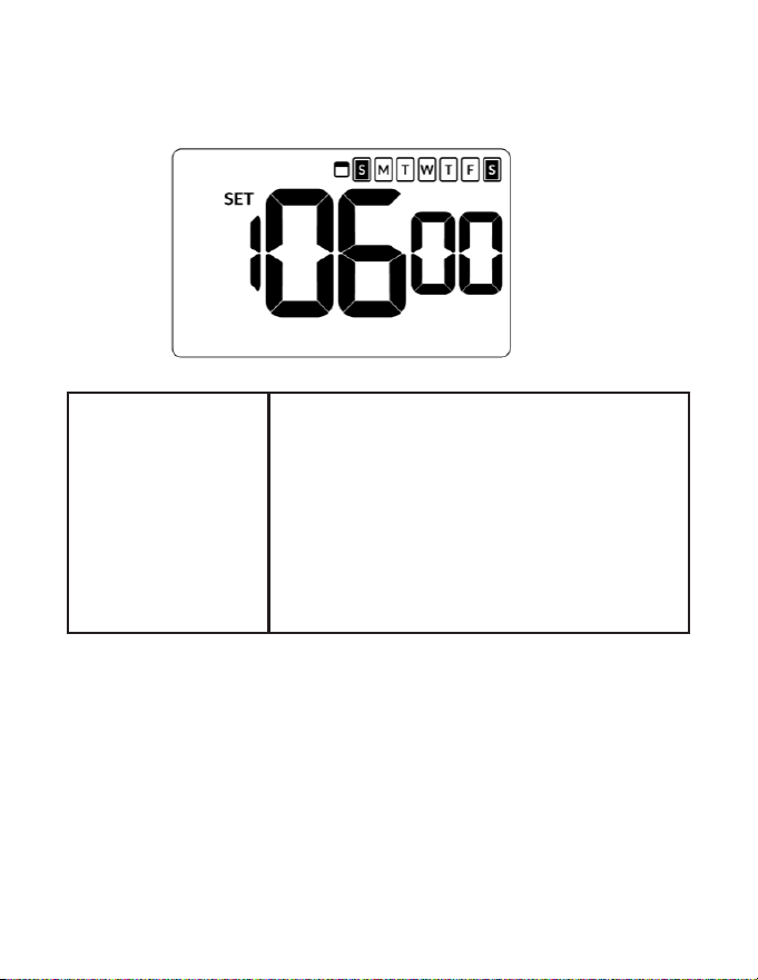
Scheduler
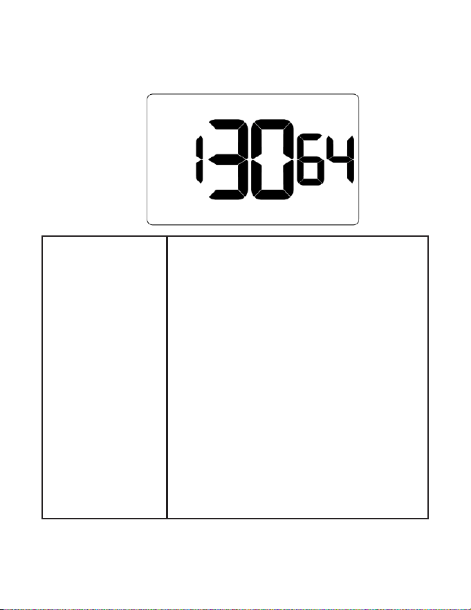
Firmware version 1130 and higher is required for Scheduler feature.
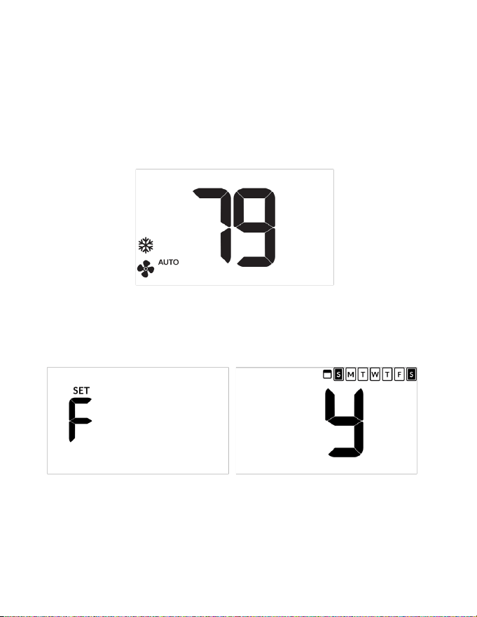
1. Ensure thermostat is powered and operational
NOTE: Below illustration is an example. Temperature and fan mode can dier.
2. Press SETTINGS button until temperature value shows
3. Press SETTINGS again to activate scheduler and show current status ( n or y)
4. Use the UP | DOWN button to select desired status
46
Custom Energy Savings Settings
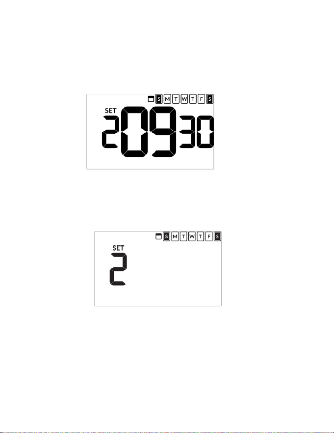
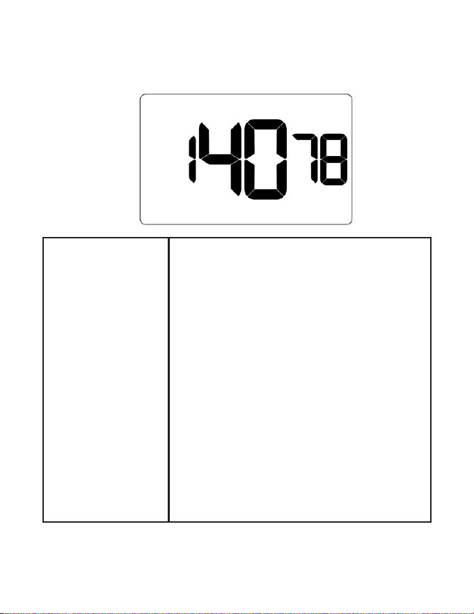
5. Press SETTINGS button to navigate to rst event of the week. Use Up / Down
arrows to set event time.
NOTE: below example shows setting for second event.
6. Press SETTINGS button to display Set and press Fan button to select
necessary day of the week. Press SETTINGS button when correct day is
selected.
NOTE: go to Step 5 immediately after selecting correct day.
47
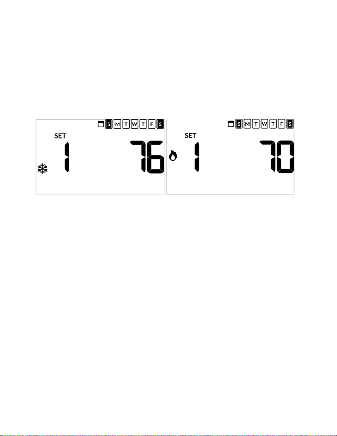
7. Use UP | DOWN buttons to set cooling temperature to desired setpoint and
press SETTINGS button.
8. Use UP | DOWN arrows to set heating setpoint.
NOTE: press ON | OFF button at anytime to exit scheduler menu.
9. Repeat Step 5 until all desired events are scheduled
Custom Energy Savings Settings

48
Custom Energy Savings Settings
Door Lock Integration
Door Lock integration can be via 1-Way Communication or 2-Way Communication.
• 1-Way application: Door locks must be networked and communicating with a
Door Lock Management System for thermostat integration
• 2-Way application: thermostat acts as the network. Door locks are not required
to be networked. A ZigBee coordinator is also required for wired / wireless
integration
NOTE: integration with dormakaba requires ebox and dorma server set-up and
communicating.
NOTE: remove faceplate from thermostat before starting procedure
1. Press and hold CONFIG button until MESH ID appears
2. Press and hold CONFIG button until type appears
3. Press FAN button until Select shows on screen
NOTE:
• Wireless: countdown appears to conrm pairing to control card
• Wired: no countdown
49
Custom Energy Savings Settings
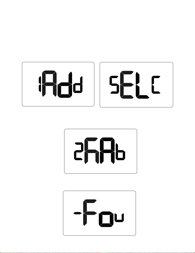
4. Press DOWN button to display Add and then press SETTINGS button to
display select list.
5. Press DOWN button until desired lock platform shows (oni or kaba) and then
press SETTINGS (below example only)
6. Allow countdown to complete until screen displays Found[1-8].
50
Custom Energy Savings Settings
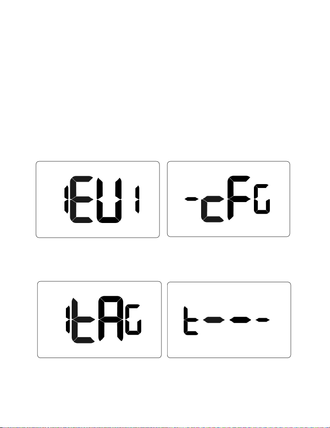
7. Use DOWN button to scroll through found devices with EuI_[lockid]_255
format.
NOTE:
• Dorma locks display as lock’s respective short ZigBee ID
• Onity locks display as lock’s respective serial number. Press SETTINGS to
select and display -cFg_[lockid]_255
8. Press DOWN one time to display the 1tag screen. Then press SETTINGS to
display t----
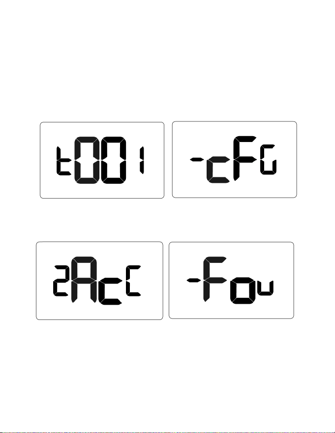
9. Use UP | DOWN buttons to select a tag number (typically 001) and then press
SETTINGS to set and display cfg_[lockid]_[tag]
10. Press DOWN button 2 times to display Acc and then press SETTINGS to
accept and re-display Found screen
11. Press ON | OFF button to exit the menu system.
51
Custom Energy Savings Settings
9. Use UP | DOWN buttons to select a tag number (typically 001) and then press
SETTINGS to set and display cfg_[lockid]_[tag]
10. Press DOWN button 2 times to display Acc and then press SETTINGS to
accept and re-display Found screen
11. Press ON | OFF button to exit the menu system.

52
Custom Energy Savings Settings
Demand Response
Demand Response (DR) is a resource for balancing power supply and demand by
allowing consumers options to reduce or shift their energy consumption away from
peak periods.
How it works
• Enroll: Tenant or Property owner opt in to recieve DR events
• Integration with Aggregators: DR aggregators linked to the property’s utility
company integrate with APIs allowing automatic transmission of DR events to
thermostats
• Active DR Event Indicator: Thermostats display a distinctive icon alerting
tenants and guests a DR event has been sent
• Opt-Out Option: Tenants and Guests may opt out of DR events by adjusting
the setpoint
NOTE: DR requires rmware 1130 or later
53
Custom Energy Savings Settings
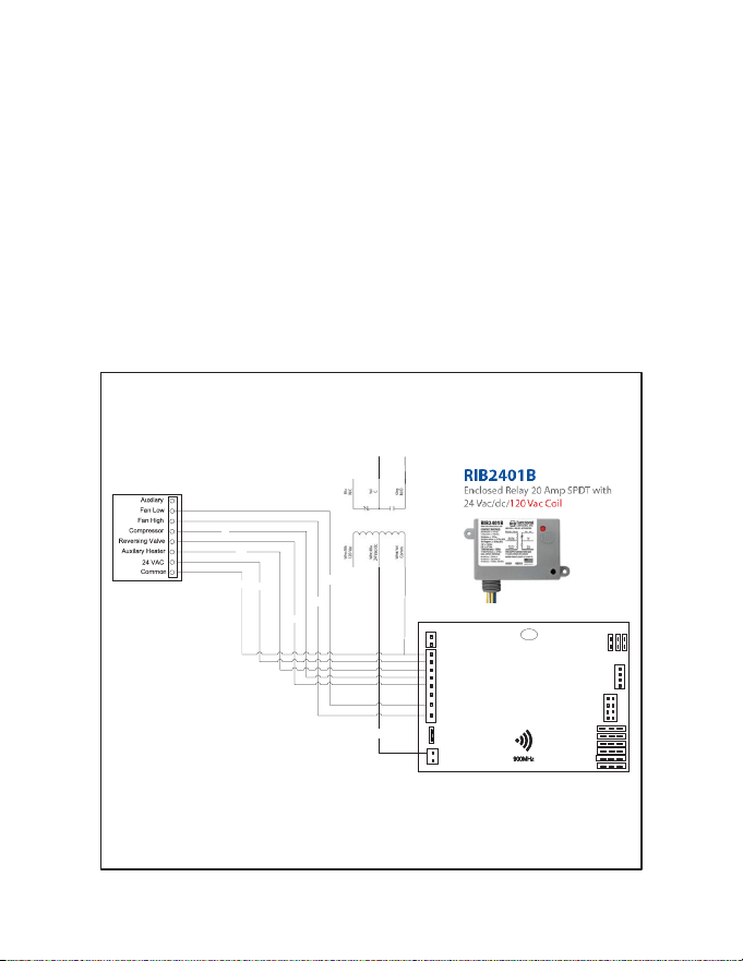
Lighting Integration
The thermostat uses built-in infrared motion sensors in conjunction with a wired
occupancy sensor to scan a room for occupancy. An auxiliary output provides a
binary signal according to real-time occupancy status in the room.
The auxiliary output is wired to a 24VAC relay installed on the lighting circuit; closing
the circuit when the room is occupied, and automatically shutting o power to the
circuit after occupancy is no longer detected.
A RIB2401B relay is recommended.
HVAC Unit
RD
YE
WH
BK
BL
OR
GR
PU
2
HVAC
CONTROLLER
C
R
W
Y
OB
AUX2
GL
GH
12V
GND
J10
OUT
OCCUPANCY OUT
IN
JUMPER
VRF
36
25
14
J5
12V
RX
J4
J6
J2
J11
J3
J9
ANALOG IN /OUT
DAC
OEM
(MIE/LG)
12 V OUT
TX
GND
C
R
W
Y
OB
AUX2
GL
GH
12V
GND
J10
OUT
OCCUPANCY OUT
IN
JUMPER
VRF
36
25
14
J5
12V
RX
J4
J2
J11
J3
J9
ANALOG IN /OUT
DAC
OEM
(MIE/LG)
12 V OUT
C
R
W
Y
OB
AUX2
GL
GH
12V
GND
J10
OUT
OCCUPANCY OUT
IN
JUMPER
VRF
36
25
14
J5
12V
RX
J4
J6
J2
J11
J3
J9
ANALOG IN /OUT
DAC
OEM
(MIE/LG)
12 V OUT
RIB2401B
ToLigh�ng Circuit

54
Custom Energy Savings Settings
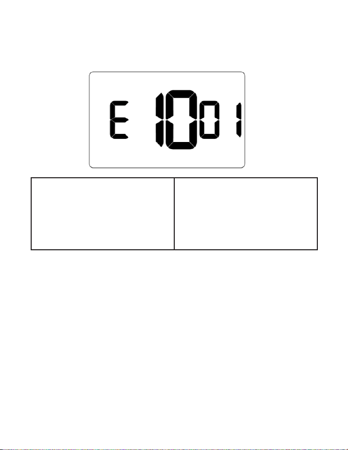
Setting Index Max Min
E1 001 000
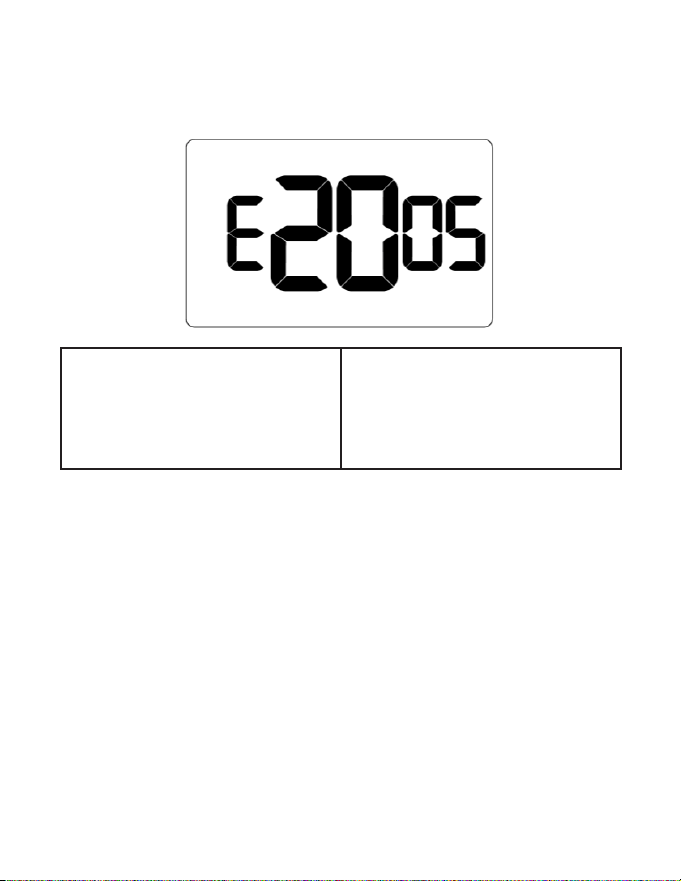
E2 030 002
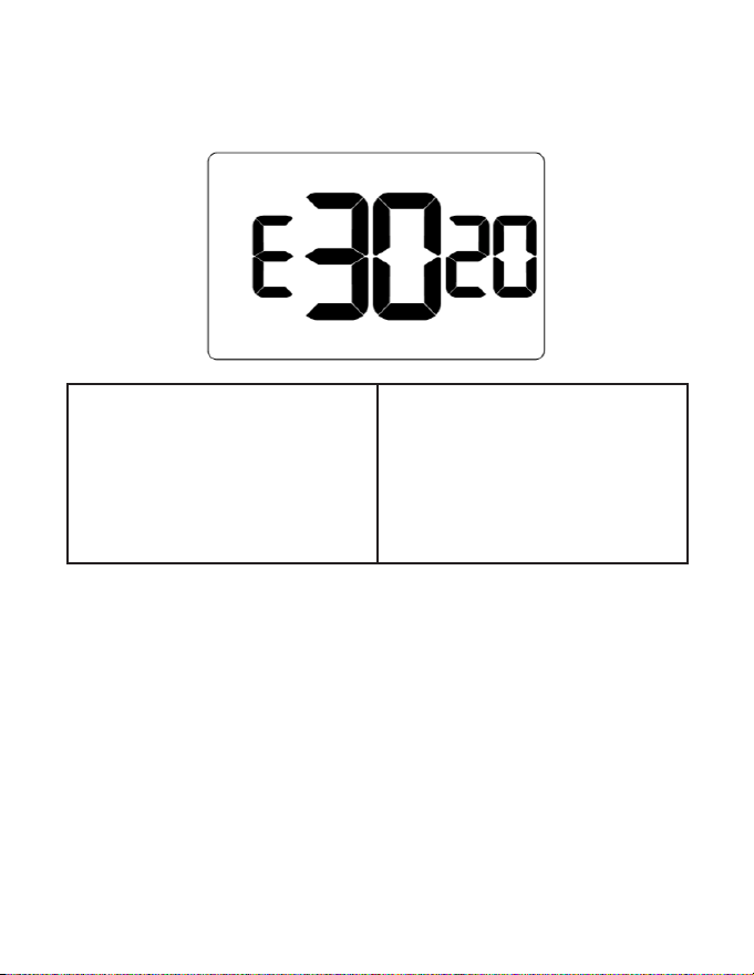
E3 020 010
E4 030 002
E5 060 000
E6 060 000
E7 060 000
E8 023 000
E9 023 000
10 060 000
11 082 062
12 120 000
13 072 052
14 092 072
15 082 062
16 084 064
17 082 060
18 001 000
19 004 000
20 001 000
21 001 000
22 NA NA

55
Custom Energy Savings Settings
Setting Index Max Min
23 020 004
24 001 000
25 030 005
26 001 000
27 070 055
28 075 065
29 NA NA
30 001 000
31 060 001
32 008 002
33 010 002
34 050 -050
35 002 001
36 001 000
37 002 000
56
01 – FAN CONTROL MODE
Custom Energy Savings Settings
Default value: 00
Range: 00-01
00: AUTOMATIC - fan runs only when
there is a demand for heating or air
conditioning
01: CONTINUOUS - fan runs
continuously when thermostat is on
57
Custom Energy Savings Settings
02 – 1
ST
STAGE DIFFERENTIAL - HEAT
Default value: 0.5F
Range: 0.2F - 3.0F
Select number of degrees thermostat
has to sense between automatic
changeover temperature for heat and
room temperature before a call for 1st
stage heating is initiated.
58
Custom Energy Savings Settings
03 – 2
ND
STAGE DIFFERENTIAL - HEAT
Default value: 2.0F
Range: 1.0F - 2.0F
Select dierence between 1st stage
heating and 2nd stage heating
initiation.
This also applies as the 3rd and 4th
stage dierential on top of the 2nd
when there are more than 2 stages.
59
Custom Energy Savings Settings
04 – 1ST STAGE DIFFERENTIAL - COOL
Default value: 0.5F
Range: 0.2F - 3.0F
Select number of degrees thermostat
has to sense between automatic
changeover temperature for cool and
room temperature before a call for 1st
stage cooling is initiated.
60
Custom Energy Savings Settings
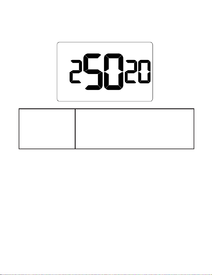
05 – INCIDENTAL OCCUPANCY THRESHOLD
Default value: 5 minutes
Range: 0 - 60 minutes
Select minimum period of time (in minutes) for which
occupancy needs to be detected to enter guest
occupancy mode. When occupancy is detected,
thermostat will switch to occupied mode for a
duration of Incidental Occupancy Threshold selected.
If occupancy is detected for a period of time shorter
than the Incidental Occupancy Threshold selected,
the thermostat will automatically revert to unoccupied
mode at the end of the Incidental Occupancy
Threshold period and continue to observe energy
saving functions that were in eect before the room
became occupied. This setting allows ignoring
incidental room visits.
If occupancy is detected for a period of time longer
than the Incidental Occupancy Threshold selected,
the thermostat will enter the guest occupancy mode.
When the thermostat is in the guest occupancy
mode, it will revert to unoccupied mode and initiate
the setback temperature only when occupancy is not
detected for the duration of the setback delay (Heat
or Cool) period.
61
Custom Energy Savings Settings
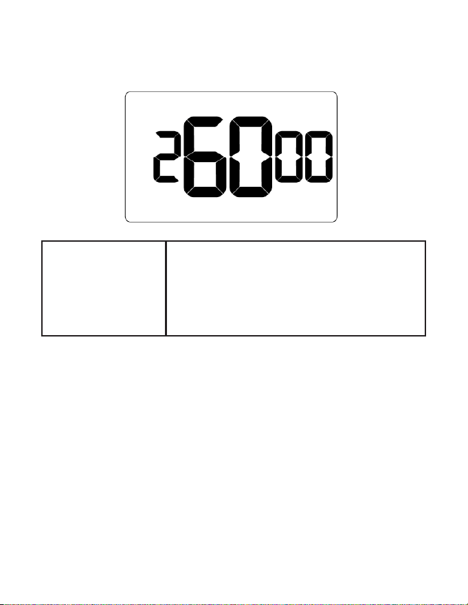
06 – NIGHT OCCUPANCY THRESHOLD
Default value: 1 minute
Range: 0 - 60 minutes
Select minimum period of time (in minutes) for
which occupancy needs to be detected to consider
the room occupied during the Night Occupancy
period. When occupancy is detected during
Night Occupancy Period for longer than the Night
Occupancy Threshold selected, the thermostat will
instantaneously switch to occupied mode.
,If occupancy is detected for a period of time shorter
than the Night Occupancy Threshold selected, the
thermostat will automatically revert to unoccupied
mode and continue to observe energy saving
functions that were in eect before the room became
occupied.
If occupancy is detected for a period of time longer
than the Night Occupancy Threshold selected, the
thermostat will disable the occupancy sensor and
consider the room occupied until the end of the Night
Occupancy period.
This feature ensures energy saving functions that may
aect guest comfort will not come in eect during the
Night Occupancy period.
62
Custom Energy Savings Settings
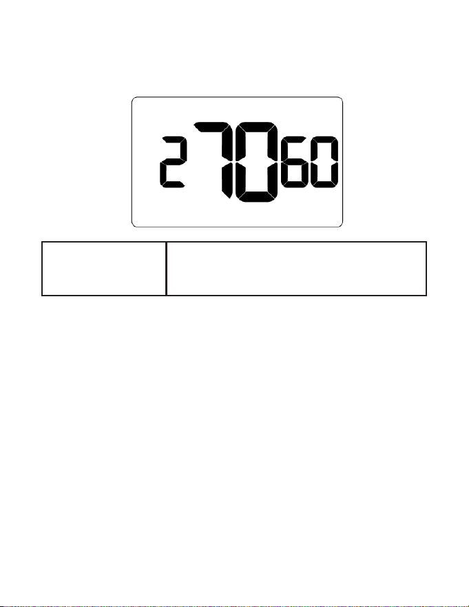
07 – FORCED 2ND STAGE HEATING
Default value: 30 minutes
Range: 0 - 60 minutes
Select a number of minutes 1st stage heating will run
before 2nd stage heating is automatically initiated if
the guest set point is not reached and the 2nd stage
heating is not initiated through dierential settings.
This feature allows automatically turning on 2nd
stage heating to avoid excessive compressor use.
Set to 00 to disable the feature.
This also applies as the 3rd and 4th stage dierential
on top of the 2nd when there are more than 2 stages.
63
Custom Energy Savings Settings
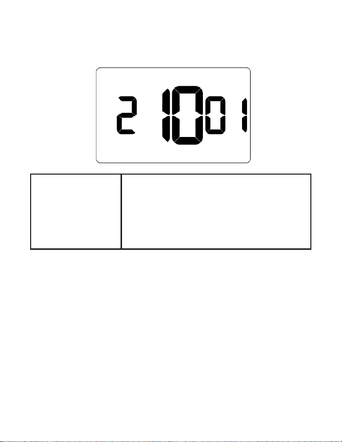
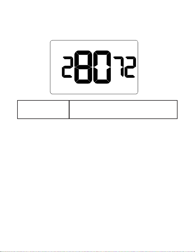
08 – NIGHT OCCUPANCY START
Default value: 21 hours
Range: 0 - 23 hours
Select the start time (24-hour clock) for Night
Occupancy
If occupancy is detected for a period of time longer
than the Night Occupancy Threshold during Night
Occupancy period, the thermostat will disable the
occupancy sensor and consider the room occupied
until the end of the Night Occupancy period.
This feature ensures that energy saving functions
that may aect guest comfort will not come in eect
during the Night Occupancy period if room was
occupied for a period of time longer than Night
Occupancy Threshold.
64
Custom Energy Savings Settings
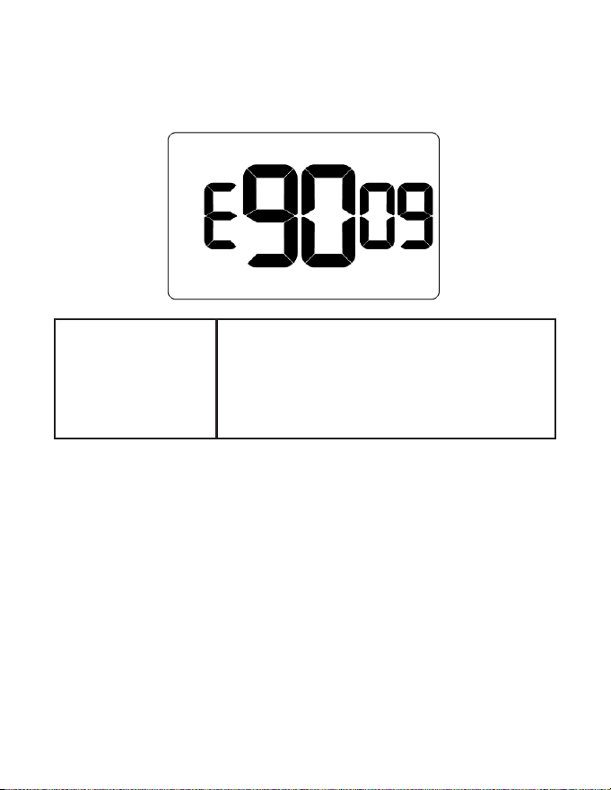
09 – NIGHT OCCUPANCY END
Default value: 9 hours
Range: 0 - 23 hours
Select time (24-hour clock) for Night Occupancy to
end.
The time of day the Night Occupancy ends and
the thermostat switches back to the room sensing
settings chosen in the other occupancy modes.
65
Custom Energy Savings Settings
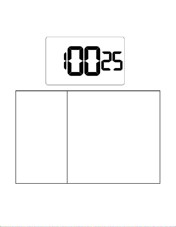
10 – TEMPERATURE RECOVERY TIME
Default value: 25 minutes
Range: 0 - 60 minutes
Select the maximum time allowed for a HVAC unit
to attain temperature as dened by Heat and Cool
Recovery Temperature;
Temperature Recovery Time selected and the
actual temperature recovery ability of the HVAC
unit are used to calculate setback temperatures.
Calculated setback temperatures maximize
energy savings and at the same time ensures a
comfortable room temperature (dened as Heat
and Cool Recovery Temperature) will be restored
within the selected Temperature Recovery Time.
Setting the Temperature Recovery Time to 00,
disables temperature recovery. When temperature
recovery is disabled, thermostat will use the
Minimum and Maximum Setback Temperatures as
setback set points.
66
Custom Energy Savings Settings
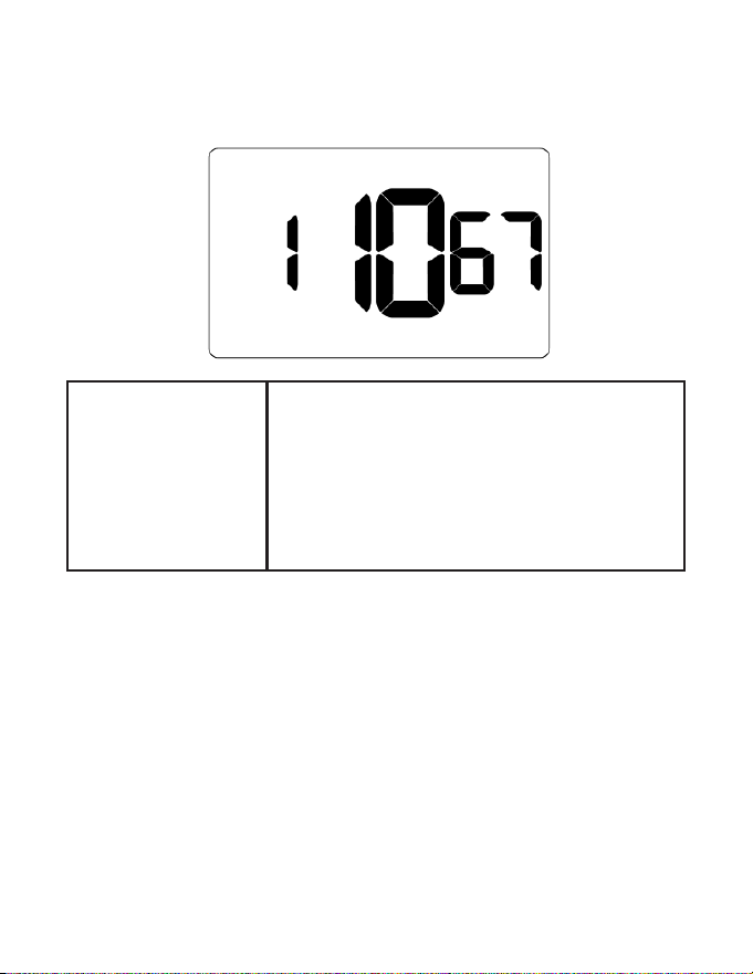
11 – RECOVERY TEMPERATURE - HEAT
Default value: 67F
Range: 62F - 82F
Select room temperature in °F that a HVAC unit
will have to attain within the selected Temperature
Recovery Time when there is a need for heating.
If recovery is disabled (Temperature Recovery Time
set to 0) or if setback temperatures have not yet been
calculated, the Recovery Temperature - Heat value
will be used as the setback temperature for heating.
67
Custom Energy Savings Settings
12 – TEMPERATURE SETBACK DELAY
Default value: 20
minutes
Range: 0 - 120 minutes
Select the time delay (in minutes) for which the
room that is in the guest occupancy mode needs to
be unoccupied before the temperature setback is
initiated.
This feature prevents initiating temperature setback
prematurely while the guest is still in the room but in
an area where occupancy cannot be detected by the
occupancy sensor.
Setting the Temperature Setback Delay - Heat to 00,
disables the setback in the heat mode. Set to 00 to
disable EMS.
68
Custom Energy Savings Settings
13 – MINIMUM SETBACK TEMPERATURE - HEAT
Default value: 64F
Range: 52F - 72F
Select Minimum Setback Temperature in °F.
Setback temperature is calculated by measuring
HVAC unit’s ability to attain Recovery Temperature -
Heat”within Temperature Recovery Time.
If recovery is disabled (Temperature Recovery Time is
set to 0) or if setback temperatures have not yet been
calculated, the Recovery Temperature - Heat value
will be used as the setback temperature for heating.
If calculated setback temperature for heating is
lower than Minimum Setback Temperature, then
the Minimum Setback Temperature will be used as
setback temperature for heating.
This feature allows dening the minimum temperature
in a room when room is unoccupied and the
thermostat is in the setback mode.
69
Custom Energy Savings Settings
14 – MAXIMUM SETBACK TEMPERATURE
Default value: 78F
Range: 72F - 92F
Select the Maximum Setback Temperature in °F.
Setback temperature is calculated by measuring
HVAC unit’s ability to attain Recovery Temperature -
Cool within Temperature Recovery Time.
If recovery is disabled (Temperature Recovery Time is
set to 0) or if setback temperatures have not yet been
calculated, the Maximum Setback Temperature value
will be used as the setback temperature for cooling.
If calculated setback temperature for air conditioning
is higher than Maximum Setback Temperature, then
the Maximum Setback Temperature will be used as
setback temperature for air conditioning.
This feature allows dening the maximum
temperature in a room when room is unoccupied and
the thermostat is in the setback mode.

70
Custom Energy Savings Settings
15 – RECOVERY TEMPERATURE - COOL
Default value: 74F
Range: 62F - 82F
Select the room temperature in °F that a HVAC unit
will have to attain within the selected Temperature
Recovery Time when there is a need for air
conditioning.
71
Custom Energy Savings Settings
16 – MINIMUM SET POINT
Default value: 66F
Range: 64F - 84F
Select the minimum set point in °F that a guest can
select.
72
Custom Energy Savings Settings
17 – MAXIMUM SET POINT
Default value: 78F
Range: 60F - 82F
Select the maximum set point in °F that a guest can
select.
73
Custom Energy Savings Settings
18 – TEMPERATURE CONTROL MODE
Default value: AUTOMATIC
Range: 00 - 01
Select Temperature Control Mode:
00: MANUAL - Allows users to select HEAT only or
COOL only temperature control mode to maintain
the room temperature
01: AUTOMATIC - Thermostat automatically turns
on heating or air conditioning to maintain the room
temperature at the selected temperature set point
74
Custom Energy Savings Settings
19 – AUTO CHANGEOVER SET POINT OFFSET
Default value: 1F
Range: 1F - 4F
Select the dierence between the guest-selected set
point and the heat and the cool set point when the
thermostat is in the automatic temperature control
mode.
This value plus the 1st stage dierential dened in
steps 2 and 4, denes the temperature at which the
thermostat would automatically change heating/
cooling modes.
This feature allows adjusting the deadband between
the heat and the cool set points in automatic
changeover mode in to avoid the system from
bouncing back and forth between heating and
cooling under normal operating conditions.
75
Custom Energy Savings Settings
20 – SETBACK SET POINTS
Default value: 01
Range: 00 - 01
00: When room is unoccupied and the thermostat is
in the setback mode or turned o, it will NOT maintain
the temperature between heat and cool setback set
points.
01: When room is unoccupied and the thermostat
is in the setback mode or turned o, it will maintain
the temperature between heat and cool setback set
points.
76
Custom Energy Savings Settings
21– AUTO-RESTORE
Default value: 01
Range: 00 - 01
00: When guest enters the room, the thermostat will
be turned o - it will not automatically restore the most
recent guest settings
01: When guest enters the room, the thermostat will
automatically restore the most recent guest settings
77
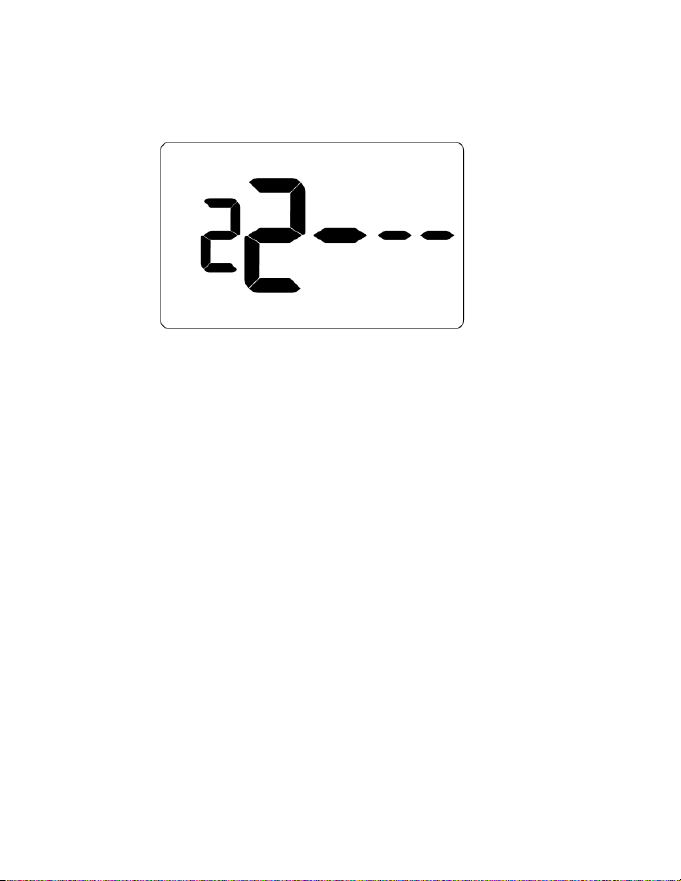
Custom Energy Savings Settings
22 – PLACEHOLDER SCREEN
NOTE: for future use
78
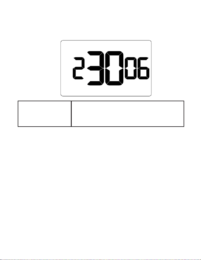
Custom Energy Savings Settings
23 – SETPOINT OVERSHOOT
Default value: 0.6F
Range: 4F - 20F
Select the °F of overshoot above or below the setpoint
on the thermostat before the thermostat stops the call
for cooling or heating.
79
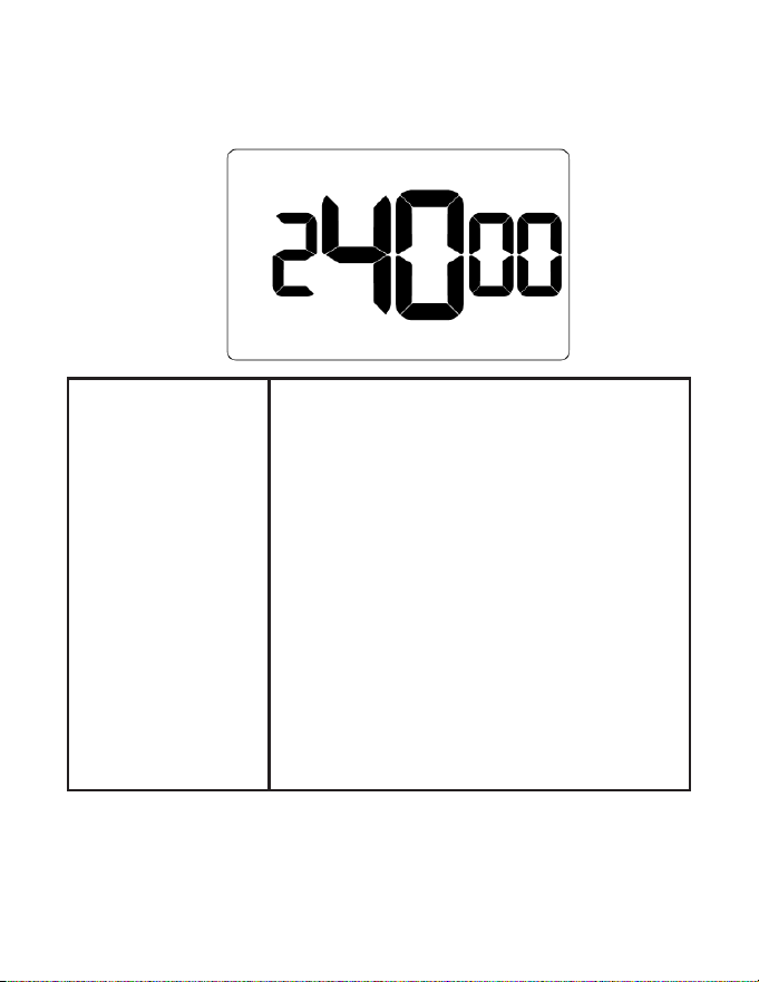
Custom Energy Savings Settings
24 – AUTOMATIC HUMIDITY CONTROL
Default value: 00
Range: 00 - 01
00: Disable automatic humidity control
01: Enable automatic humidity control
When Automatic Humidity Control is enabled,
thermostat will turn on air conditioning in an
unoccupied room when humidity raises above 60%
and room temperature is above 72°F until either room
humidity is below 55% or room temperature is below
72°F
This setting is active only on thermostats with enabled
humidity features. Changing this setting on a non-
humidity thermostat will have no eect on thermostat
operation.
Humidity features can be enabled on compatible
thermostats via online management.
80
Custom Energy Savings Settings
25 – 2ND STAGE COOL DIFFERENTIAL
Default value: 2F
Range: 5F - 30F
Select the °F dierential required to trigger 2nd stage
cooling (if applicable).
This also applies as the 3rd and 4th stage dierential
on top of the 2nd when there are more than 2 stages.
81
Custom Energy Savings Settings
26 – SMART SETBACK
Default value: 00
Range: 00 - 01
Smart setback reduces the excessive heating
or cooling that may occur when occupants set
their thermostats to setpoints outside of the norm.
Occupant setpoint that is greater than Cool Setback
or less than Heat Setback will be respected during
setbacks to save energy.
82
Custom Energy Savings Settings
27 – HUMIDITY CONTROL THRESHOLD
Default value: 60F
Range: 55F - 70F
Select the relative humidity level that automatic
humidity control will attempt to control in conjunction
with the humidity cut-o temp.
83
Custom Energy Savings Settings
28 – HUMIDITY CUTOFF TEMPERATURE
Default value: 72F
Range: 65F - 75F
Select the temperature at which humidity control will
shut o.
84
Custom Energy Savings Settings
29– PLACEHOLDER SCREEN
NOTE: for future use
85
Custom Energy Savings Settings
30– ENERGY MANAGEMENT ON/OFF
Default value: 01
Range: 00 - 01
00: Energy management disabled
01: Energy management enabled
86
Custom Energy Savings Settings
31– DOOR/WINDOW SHUT OFF DELAY
Default value: 2
Range: 1 - 60
Select the time delay (in minutes) before the
thermostat disables air conditioning when a door or
window sensor has been installed.
87
Custom Energy Savings Settings
32– AUTO FAN SPEED 1ST STAGE DIFFERENTIAL
Default value: 2F
Range: 1F - 8F
Select the °F dierential between Low Fan and 2nd
stage fan (Medium or High) when Auto-Fan Speed is
selected.
88
Custom Energy Savings Settings
33– AUTO FAN SPEED 2ND STAGE DIFFERENTIAL
Default value: 4F
Range: 2F - 10F
Select the °F dierential between Medium and High
Fan when Auto-Fan Speed is selected (only active if 3
fan speeds are available).
89
Custom Energy Savings Settings
34 – TEMPERATURE CALIBRATION
Default value: 0F
Range: -5F - 5F
Calibrate the temperature display
90
Custom Energy Savings Settings
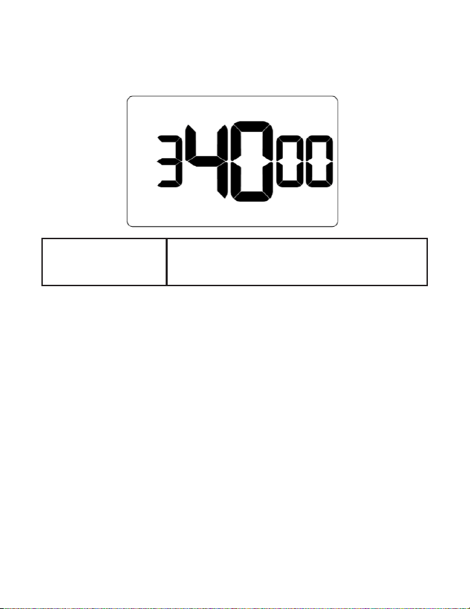
35 – AUTOMODE TYPE
Default value: 01
Range: 01 - 02
01: Standard Auto Mode - The thermostat will apply
the deadband on the guest setpoint and control
temperature with the guest setpoint as the median
02: Changeover Auto Mode - The thermostat will
apply the deadband as a changeover limit where the
deadband is crossed triggering a change in heating
or cooling mode
91
Custom Energy Savings Settings
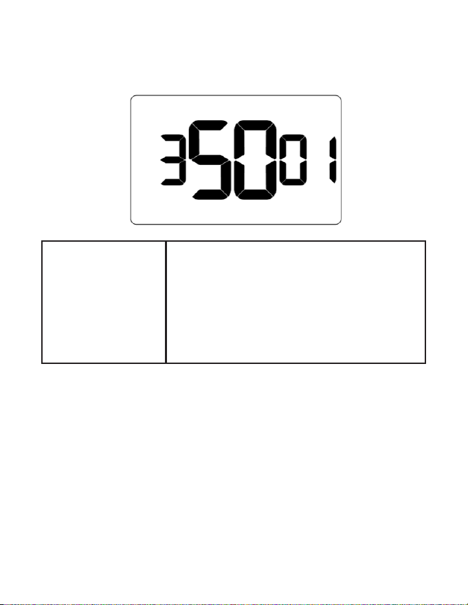
36 – HUMIDITY CONTROL OCCUPIED ROOM
Default value: 00
Range: 00 - 01
00: Humidity control OFF - The thermostat will disable
humidity control when the room is occupied
01: Humidity control ON - The thermostat will enable
humidity control even when the room is occupied
92
Custom Energy Savings Settings
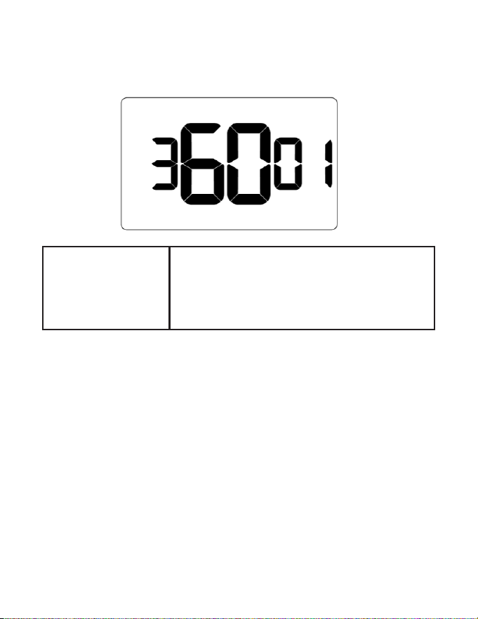
37 – HEAT EQUIPMENT LOCKOUT
Default value: 00
Range: 00 - 02
00: Compressor lockout - If set to 1, the thermostat will
only allow electric heat
01: Electric heat lockout - If set to 2, the thermostat will
only allow compressor heat.
02: Equipment lockout is disabled - The thermostat
will enable both compressor and electric heat
93
Troubleshooting
Restoring Factory Settings
For reported errors or conguration issues, restore settings to thermostat default
parameters and re-pair with HVAC Controller.
1. Press and hold the FAN and SYSTEM MODE buttons together for 3 seconds to
enter meshID screen
2. Press SETTINGS to navigate to clock conguration screen.
3. Press and hold FAN and SYSTEM MODE buttons until thermostat displays RST,
then press SETTINGS button
4. Verify thermostat displays SETUP after three (3) seconds and recongure
thermostat
Contact technical support if the issues are not resolved.

94
APPENDIX 1 - Energy Saving Presets
Bolded values below indicate the factory default prole*
Level
0*
Level
1
Level
2
Level
3
Level
4
Level
5
Fan Control Mode AUTO AUTO AUTO AUTO AUTO AUTO
1st Stage Dierential Heat 005 005 005 005 005 005
2nd Stage Dierential Heat 010 010 010 020 020 020
1st Stage Dierential Cool 005 005 005 005 005 005
Guest Occupancy Threshold
000 005 005 005 005 005
Night Occupancy Threshold 001 001 001 001 001 001
Force 2nd Stage Heating After 030 030 030 030 030 030
Night Occupancy Start 018 019 020 021 022 023
Night Occupancy End 012 011 010 009 008 007
Temperature Recovery Time 000 015 020 025 030 000
Recovery Temperature Heat 070 069 068 067 066 065
Temperature Setback Delay 000 030 025 020 015 010
Minimum Setback Temperature 067 066 065 064 063 062
Maximum Setback Temperature 072 074 076 078 080 082
Recovery Temperature Cool 071 072 073 074 075 076
Minimum Set point 064 064 065 066 067 068
Maximum Set point 082 082 080 078 076 074
Temperature Control Mode AUTO AUTO AUTO AUTO AUTO AUTO
Auto Changeover Set Point Oset
Dead Band)
001 001 001 001 001 001

95
APPENDIX 1 - Energy Saving Presets
Level
0
Level
1
Level
2
Level
3
Level
4
Level
5
Setback Set Points OFF ON ON ON ON ON
Auto Restore OFF ON ON ON ON ON
N/A
Setpoint Overshoot 006 006 006 006 006 006
Automatic Humidity Control OFF OFF OFF OFF OFF OFF
2nd Stage Cool Dierential 010 010 010 020 020 020
Smart Setback OFF OFF OFF OFF OFF OFF
Humidity Control Threshold 060 060 060 060 060 060
Humidity Cuto Temperature 072 072 072 072 072 072
N/A
Energy Management On/O OFF ON ON ON ON ON
Door/Window Shuto Delay 002 002 002 002 002 002
Auto Fan Speed 1st Stage Dierential 002 002 002 002 002 002
Auto Fan Speed 2nd Stage Dierential 004 004 004 004 004 004
Temperature Calibration 000 000 000 000 000 000
Automode Type STD STD STD STD STD STD
Humidity Control Occupied Room OFF OFF OFF OFF OFF OFF
Heat Equipment Lockout 000 000 000 000 000 000

96
APPENDIX 2 - Equipment Codes
Outputs
EQPT Code J3 port J9 port
Color White Yellow Orange Purple Green Brown Blue
0101 W1 X X X GH X OCC
0102 W1 X X GL GH X OCC
0103 W1 X GM GL GH X OCC
0302 GH WCW WCCW GL X X OCC
0303 GH WCW WCCW GL GM X OCC
1001 X Y1 O X GH X OCC
1002 X Y1 O GL GH X OCC
1011 X Y1 B X GH X OCC
1012 X Y1 B GL GH X OCC
1101 W1 Y1 O X GH X OCC
1102 W1 Y1 O GL GH X OCC
1111 W1 Y1 B X GH X OCC
1112 W1 Y1 B GL GH X OCC
1201 WAUX Y1 O X GH X OCC
1202 WAUX Y1 O GL GH X OCC
1211 WAUX Y1 B X GH X OCC
1212 WAUX Y1 B GL GH X OCC
2001 X Y1 X X GH X OCC
2002 X Y1 X GL GH X OCC
2003 X Y1 GM GL GH X OCC
2100 W1 Y1 X X X X OCC
2101 W1 Y1 X X GH X OCC

97
APPENDIX 2 - Equipment Codes
Outputs
EQPT Code J3 port J9 port
Color White Yellow Orange Purple Green Brown Blue
2102 W1 Y1 X GL GH X OCC
2103 W1 Y1 GM GL GH X OCC
2106 W1 Y1 X X X X OCC
2502 Y1 W1 W2 GL GH X OCC
5501 Y1 Y2 W1 W2 GH X X
5502 Y1 Y2 W1 W2 GH X GL
Outputs
Analog output Connections (J6 Port)
EQPT
Code
J3 port J9 port O0 GND O1 O2
Color
White Yellow Orange Purple Green Brown Blue White Black Yellow Green
4403
X X GM GL GH X OCC
Analog
Heat
GND
Analog
Cool
X
4406
X X X X X X OCC
Analog
Heat
GND
Analog
Cool
Analog
Fan

98
“Automatic Fan Control Mode” - fan runs only when there
is a demand for heating or cooling;
“Manual Fan Control Mode” - guest can select between
automatic or continuous fan operation;
“Minimum Set point” - minimum temperature that a guest
can request;
“Maximum Set point” - maximum temperature that a guest
can request;
“Auto Changeover Set Point Oset” - the dierence
between the guest-selected set point and the heat and
cool changeover temperatures;
“1st Stage Dierential - Heat” - the temperature that
the thermostat has to sense between the automatic
changeover temperature for heat and the room
temperature before a call for the 1st stage heating is
initiated;
“2nd Stage Dierential - Heat” - dierence between 1st
stage heating temperature and room temperature before
the 2nd stage heating is initiated;
“1st Stage Dierential - Cool” - the temperature that
the thermostat has to sense between the automatic
changeover temperature for cool and the room
temperature before a call for the 1st stage cooling is
initiated;
“Forced 2nd Stage Heating” - number of minutes 1st
stage heating will run before 2nd stage heating is
automatically initiated if the guest set point is not reached
and the 2nd stage heating is not initiated through
dierential settings
“Temperature Recovery Time” - the maximum period of
time allowed for restoring the “Recovery Temperature”;
“Recovery Temperature” - the room temperature that
needs to be restored within the “Temperature Recovery
Time”;
“Maximum Setback Temperature” - the highest room
temperature allowed when thermostat is in the setback
mode;
“Minimum Setback Temperature” - the lowest room
temperature allowed when thermostat is in the setback
mode;
“Temperature Setback Delay” - the length of time for
which the room that is in the guest occupancy mode
needs to be unoccupied before the temperature setback
is initiated;
Incidental Occupancy Threshold - the minimum period
of time (in minutes) for which occupancy needs to be
detected in order to enter the “Guest Occupancy” mode;
Night Occupancy Threshold - the minimum period
of time during the Night Occupancy period for which
occupancy needs to be detected in order to enter the
Night Occupancy mode;
Night Occupancy Period - The period of time during the
day during which the Night Occupancy mode can be
activated if occupancy longer than the Night Occupancy
Threshold is detected;
“Auto Restore On” - thermostat will restore the most recent
guest settings when new occupancy is detected;
“Auto Restore O” - thermostat will NOT restore the most
recent guest and will remain turned o settings when new
occupancy is detected;
“Setback Set points On” - thermostat will maintain setback
temperatures when room is unoccupied;
“Setback Set points O” - thermostat will NOT maintain
setback temperatures when room is unoccupied;
“Incidental Occupancy” - occupancy shorter than the
Incidental Occupancy Threshold;
“Guest Occupancy” - occupancy longer than the
Incidental Occupancy Threshold;
“Temperature Setback” - thermostat maintains setback
temperatures and not the guest set point temperature in
order to save energy;
“Night Occupancy Mode” - thermostat status during
which setback mode is disabled if occupancy longer than
Night Occupancy Threshold is detected within the “Nigh
Occupancy” period;
“Automatic Temperature Changeover” - thermostat
automatically activates heating or cooling to maintain the
desired room temperature;
“External Thermostat” (Class 2) mode - HVAC unit setting
allowing it to be controlled by a remote thermostat;
APPENDIX 3 - Glossary

99
Warranty Information
Refer to www.verdant.co/verdant-warranty information.
100
Technical Specications
Product Type Thermostat
White Model
White Model
Black Model
Black Model
Description
Description
VRPXEMWRTA4
VRPXEMWRTA4
VRPXEMWRTB4
VRPXEMWRTB4
RS-485 12VDC Communicating
RS-485 12VDC Communicating
DSSXEMWRTA4
DSSXEMWRTA4
N/A
N/A
DSS 12VDC Communicating
DSS 12VDC Communicating
Wireless Frequency 902-928MHz
Case Dimensions 5.60 x 3.46” x 0.937” (142.3mm x 88mm x 23.8mm)
Screen Dimensions 2.60” x 1.5” (66.1mm x 38.1mm)
Operating Voltage
2 x 1.5VDC AA Alkaline Non-rechargeable Batteries - Not Supplied 24VAC
or 12VDC
Control Outputs
(24VAC)
(1.5A maximum per
terminal, 2.5A maxi-
mum all terminals
combined)
N/A
Power Supply Outlet
N/A
Occupancy Sensor
Detection Range
Horizontal (FOV 100°)
Temperature Ac-
curacy
±1°F
Enclosure Material SABIC PC/ABS CYCOLOY C2800
Ambient Operating
Temp
32°F -105°F | 0 - 41°C
Internet Connectivity N/A
FCC ID 2A4JN-VX4001
IC 28229-VX4001

101
Technical Specications
Product Type HVAC Controller Gateway
SKU(s) EMCC6R4 EMOCT4
Wireless Frequency 902-928MHz N/A
Case Dimensions
4.08” x 2.76” x 1.02”
104mm x 70mm x 26mm
4.72” x 3.15” x 1.18”
120mm x 80mm x 30mm
Operating Voltage
24VAC (20-30VAC) | 12VDC ( 9-15VDC)
12VDC 1.5A
Technical Specications for Thermostats (cont’d)

102
Technical Specications
Product Type HVAC Controller Gateway
Control Outputs
(24VAC/12VDC)
(1.5A maximum
per terminal, 2.5A
maximum all terminals
combined)
Common (J3-C) )
N/A
24 VAC (J3-R)
Heat (J3-W)
Compressor (J3-Y) )
Reversing Valve (J3-OB)
Auxiliary (J3-AUX2) /
Fan Low (J3-GL) / AUX1 In (J9)
Fan High (J3-GH) / AUX1 Out (J9)
N/A / RS485A
N/A / RS485B
N/A / 12 VDC (J11)
N/A / GND (J11)
Power Supply Outlet
12VDC @ 0.05A (Max) N/A N/A
Occupancy Sensor
Beam Width
N/A N/A N/A
Temperature Accuracy ±1°F N/A N/A
Enclosure Material
ABS+PC (TAIRILOY® AC3100 (Formo-
sa Chemicals & Fibre Corporation))
Extruded Aluminum
Ambient Operating
Temp
32°F -105°F | 0 - 41°C 32°F -105°F | 0 - 41°C
Internet Connectivity N/A 100M/1000M Base-T Ethernet
FCC ID XEY-ZX-LV
IC 8410A-ZX-LV
Technical Specications for HVAC Controller (cont’d)

103
Technical Specications
Product Type Root Node
Sensors
SKU(s) ZX-RN
EMRWOS4
EMRDS4
EMRTS4
Wireless Frequency 902-928MHz 902-928MHz
Case Dimensions
2.4” x 1.54” x 0.78”
46mm x 61mm x 19mm
1.82” x 2.4” x 0.74”
46mm x 61mm x 19mm
Operating Voltage +5VDC (nom.)
2 1.5VDC AAA Alkaline Non-rechargeable
Batteries - Not Supplied
Control Outputs
(24VAC)
(1.5A maximum per
terminal, 2.5A maxi-
mum all terminals
combined)
N/A N/A
Power Supply Outlet
N/A N/A
Occupancy Sensor
Beam Width
N/A ±47° (94°)
Temperature Ac-
curacy
±1°F ±1°F
Enclosure Material ABS (AF312C(LG CHEM))
ABS+PC (TAIRILOY® AC3100 (Formosa
Chemicals & Fibre Corporation))
Ambient Operating
Temp
32°F -105°F | 0 - 41°C 32°F -105°F | 0 - 41°C
Internet Connectivity N/A N/A
FCC ID XEY-ZX-RN XEYZ9RF
IC 8410A-ZXRN 8410A-Z9RF

104
THIS DEVICE COMPLIES WITH PART 15 OF THE FCC RULES. OPERATION IS SUBJECT
TO THE FOLLOWING TWO CONDITIONS: (1) THIS DEVICE MAY NOT CAUSE HARMFUL
INTERFERENCE, AND (2) THIS DEVICE MUST ACCEPT ANY INTERFERENCE RECEIVED,
INCLUDING INTERFERENCE THAT MAY CAUSE UNDESIRED OPERATION.
THE MANUFACTURER IS NOT RESPONSIBLE FOR ANY RADIO OR TV INTERFERENCE CAUSED
BY UNAUTHORIZED MODIFICATIONS TO THIS EQUIPMENT. SUCH MODIFICATIONS COULD VOID
THE USER’S AUTHORITY TO OPERATE THE EQUIPMENT
This device complies with Industry Canada license-exempt RSS standard(s). Operation is subject to
the following two conditions: (1) this device may not cause interference, and (2) this device must
accept any interference, including interference that may cause undesired operation of the device.
Le présent appareil est conforme aux CNR d’Industrie Canada applicables aux appareils radio
exempts de licence. L’exploitation est autorisée aux deux conditions suivantes : (1) l’appareil ne
doit pas produire de brouillage, et (2) l’utilisateur de l’appareil doit accepter tout brouillage radio
électrique subi, même si le brouillageest susceptible d’en compromettre le fonctionnement.
Under Industry Canada regulations, this radio transmitter may only operate using an antenna of
a type and maximum (or lesser) gain approved for the transmitter by Industry Canada. To reduce
potential radio interference to other users, the antenna type and its gain should be so chosen that
the equivalent isotropically radiated power (e.i.r.p.) is not more than that necessary for successful
communication.
Conformément à la réglementation d’Industrie Canada, le présent émetteur radio peut fonctionner
avec une antenne d’un type et d’un gain maximal (ou inférieur) approuvé pour l’émetteur par
Industrie Canada. Dans le but de réduire les risques de brouillage radioélectrique à l’intention
des autres utilisateurs, il faut choisir le type d’antenne et son gain de sorte que la puissance
isotroperayonnéequivalente (p.i.r.e.) ne dépassepas l’intensité nécessaire à l’établissement d’une
communication satisfaisante.
COVERED BY ONE OR MORE OF THE FOLLOWING PATENTS. US PATENTS: 8,369,994; 8,141,791; 7,918,406; 7,232,075;
7,185,825; 7,156,318; 7,152,806; 7,145,110; 7,050,026; 7,028,912; 6,902,117; 6,789,739; 6,786,421; 6,619,555; 6,581,846;
6,578,770; 7,838,803; 7,841,542; D556,061; D518,744; RE40,437; CANADIAN PATENTS: 2,633,113; 2,633,200; OTHER
PATENTS PENDING.
Verdant Environmental Technologies, Inc. reserves the right to make changes, without notice, in design or
components. Product appearance may vary. © Verdant Environmental Technologies, Inc. 2024.
Printed in Canada. NOVEMBER 2024
TECHNICAL SUPPORT: verdant.suppor[email protected] 1-877-318-1823