www.hifiengine.com
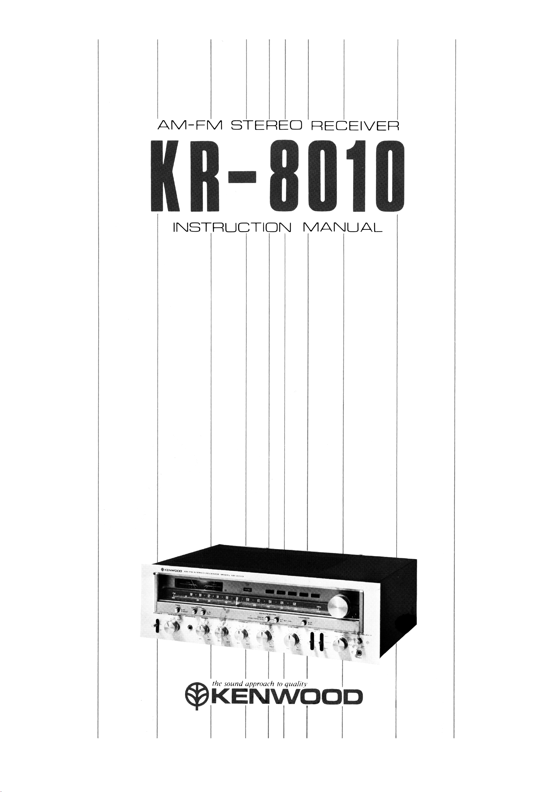
AM-FM STEREO RECEIVER
KR-8010
INSTRUCTION
KENWOOD
the sound approach to quality
*KENWOOD
www.hifiengine.com
INTRODUCTION
The purpose of this manual is to acquaint you with
the operating features of this receiver. You will
notice that in every detail of planning, engineering,
styling, operating convenience, and adaptability,
we have sought to anticipate your needs and
desires.
We suggest that you read through this manual
carefully. Knowing how to set up the receiver, to
the best advantage, will enhance your listening
pleasure right from the start. You will also
become aware of the ease with which you can
adjust the receiver to meet your special re-
quirements.
SERIAL NUMBER
Record your SERIAL NUMBER on the spaces
designated on the warranty card. You will find the
serial number on the back of the receiver.
AFTER UNPACKING
After unpacking, we recommend you inspect and
examine the receiver for any possible shipping
damage. If your receiver is damaged or fails to
operate, notify your dealer immediately. If your
receiver was shipped to you directly, notify the
shipping company without delay. Only the con-
signee (the person or company receiving the
receiver) can file a claim against the carrier for
shipping damage.
We recommend you retain the original carton and
packing materials to prevent any damage should
you transport or ship your receiver in the future.
INSTALLATION PRECAUTIONS
a) Avoid locations subject to direct sunlight.
b) Avoid high or low temperature extremes.
c) Keep the receiver away from heat radiating
source.
d) Choose stable locations with as little vibra-
tion and dust as possible.
WARNING:
TO PREVENT FIRE OR SHOCK
HAZARD, DO NOT EXPOSE
THIS APPLIANCE TO RAIN OR
MOISTURE
2
1.
2.
IMPORTANT!
Receivers shipped to U.S.A. and Canada
are designed to operate on 120 volts AC
only.
They are not equipped with an AC
Voltage Selector Switch and the follow-
ing description on such a switch should
be disregarded.
Receivers shipped to all other countries
are equipped with an AC Voltage Selec-
tor Switch on the rear panel. The
following description should be carefully
read.
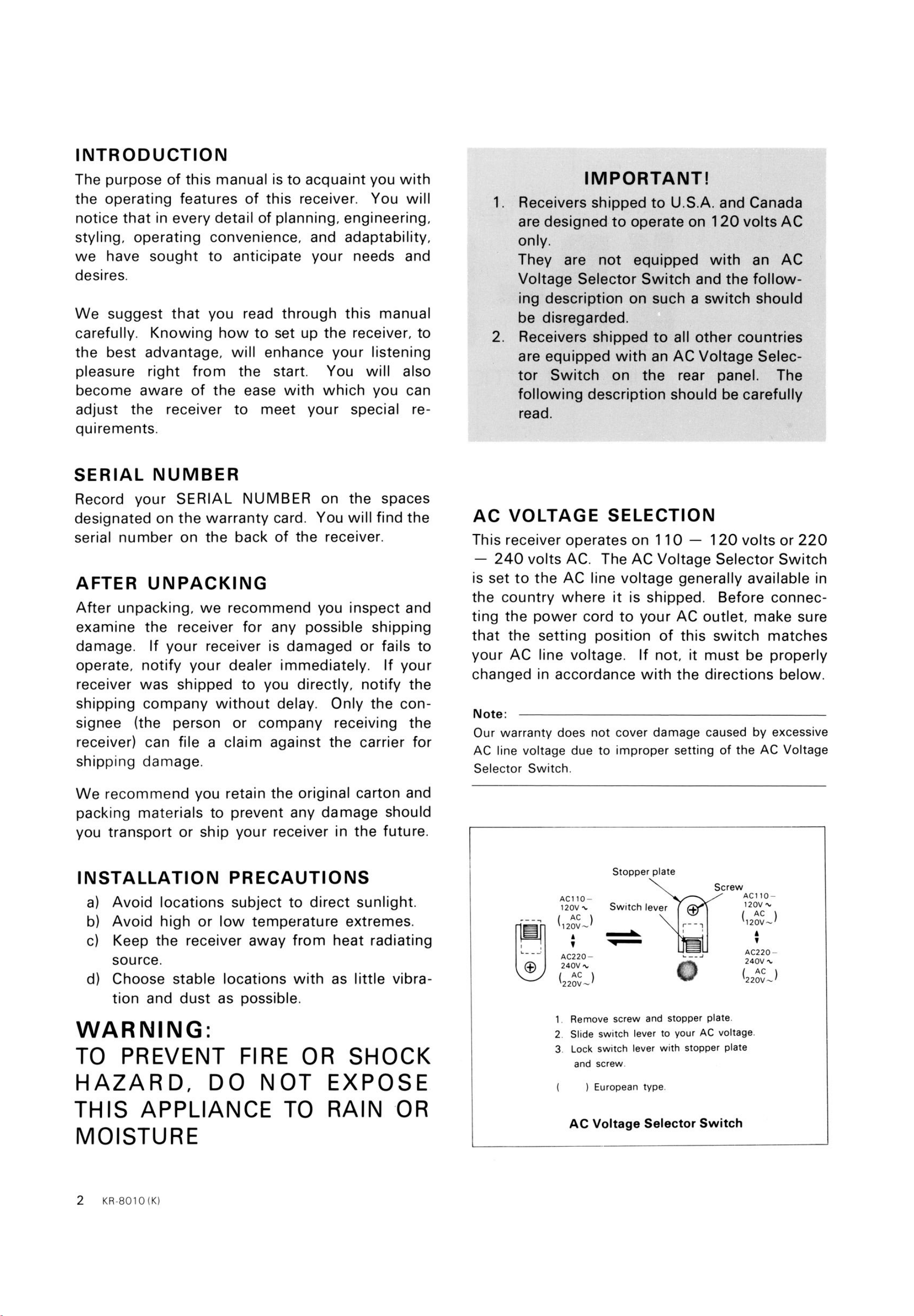
AC VOLTAGE SELECTION
This receiver operates on 1 10 — 120 volts or 220
— 240 volts AC. The AC Voltage Selector Switch
is set to the AC line voltage generally available in
the country where it is shipped. Before connec-
ting the power cord to your AC outlet, make sure
that the setting position of this switch matches
your AC line voltage. If not, it must be properly
changed in accordance with the directions below.
Note:
Our warranty does not cover damage caused by excessive
AC line voltage due to improper setting of the AC Voltage
Selector Switch.
Stopper plate
Switch lever
ACIIO—
120V
( AC )
120V
AC220—
240V
( AC )
220V
Screw
ACIIO—
120V
( AC )
120V—
AC220
240V
220V—
1
2
3
Remove screw and stopper plate
Slide switch lever to your AC voltage.
Lock switch lever with stopper plate
and screw.
) European type.
AC Voltage Selector Switch
www.hifiengine.com
CONTENTS
FEATURES
INTERCONNECTING DIAGRAM
CONNECTING INSTRUCTIONS
CONTROLS AND FUNCTIONS
OPERATING INSTRUCTIONS
BEFORE ASKING SERVICE
SPECIFICATIONS
FEATURES
3
4
5
8
10
14
16
1
2.
3.
4.
5.
6.
High Power Output with Low Distortion.
125 watts per channel, min. RMS both
channels driven, at 8 ohms, from 20 Hz to
20,000 Hz with no more than 0.03% total
harmonic distortion.
Perfect protection circuit with ASO circuitry
and mechanical relay.
Very Quiet: 84 dB of phono S/ N (Signal to
Noise) ratio at 2.5 mV input.
Triple Tone Controls with true Defeat switch.
Sound Injection System for adding a voice of
your own.
High Sensitive FM Front end with Dual Gate
MOS FET and 4 gang V.C. (Variable
Capacitor).
7.
8.
9.
10.
Low Distortion and High Selectivity IF sec-
tion with Two Differential IC and Newly
Developped Four 2 element Ceramic Filters.
FM MUTING has an outstanding two
different level positions and performs
by automatic switching cir-
cuit at low input antenna level.
Pilot Signal Canceler and Steep Slope 2 Pole
LC Filter for Interference of Carrier Leakage.
Many Useful Functions:
Three Speaker Systems Selector.
Two Tape Monitors with Through Circuit.
De-emphasis Selector as 25, 50 and 75
us.
And High Filter, Subsonic Filter, Loudness
Control, Mode Selector as Stereo/ Mono.
SAFETY PRECAUTIONS
Ventilation
Never close the ventilation holes on the
case top with a record, table cloth, curtain,
etc. Nothing must be put on the receiver
especially when using for a long time.
Keep the receiver at least four inches
(about ten centimeters) away from the
wall and other things.
Cleaning
Do not use volatile liquid such as alcohol,
thinner, gasoline, benzine, etc., when
cleaning the receiver surface. Use silicon
cloth or soft dry cloth.
Modification
Never dismantle the case from the receiver
and touch the internal part. Never modify
the internal part. Otherwise, the danger of
electric shock will be incurred.
Extraneous Matter
Do not put on and near the receiver what
contains water (vase, pitcher, etc.).
Do not drop in the receiver the inflam-
mable (paper, celluloid, etc.) and the metal
(needle, hairpin, coin, etc.).
KR-8010 (K)
3
www.hifiengine.com
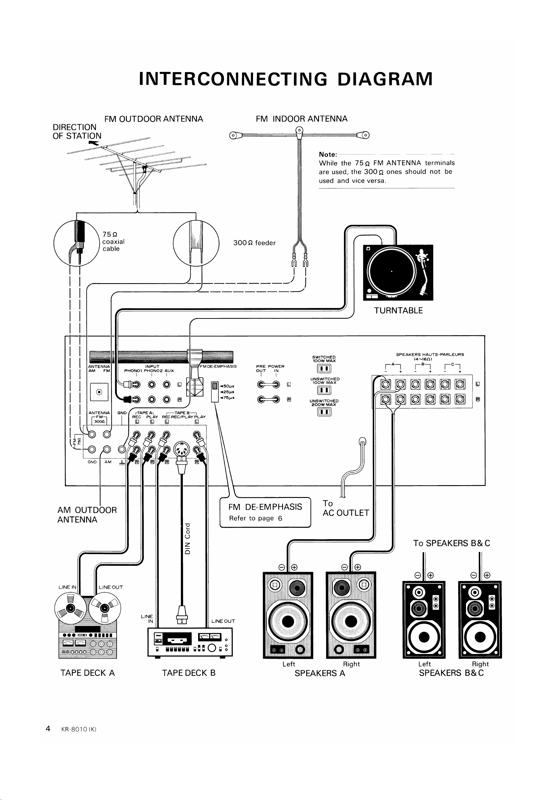
FM OUTDOOR ANTENNA
DIRECTION
OF STATION
INTERCONNECTING DIAGRAM
-J
75Q
coaxial
cable
ANTENNA
AM FM
ANTENNA
FM INDOOR ANTENNA
Note:
While the 75Q FM ANTENNA terminals
are used, the 300Q ones should not be
used and vice versa.
300 Q feeder
TURNTABLE
INPUT
PHONO' PHON02 Aux
FM DE-EMPHASIS
our
POWER
IN
O
rTAPE An
REC PLAY
LINE
IN
SWITCHED
IOOW MAX
11
UNSWITCHED
IOOW MAX
UNSWITCHED
200W MAX
To
AC OUTLET
Right
lel
o
o
GND
o
O
AM OUTDOOR
ANTENNA
REC REC/PLAY PLAY
o
z
SPEAKERS HAUTS-PARLEURS
To SPEAKERS C
LINE IN
O
LINEOUT
QOO
FM DE-EMPHASIS
Refer to page 6
LINE OUT
iiiiii
TAPE DECK B
Left Left
SPEAKERS
Right
4
TAPE DECK A
KR-8010 (K)
SPEAKERS A
www.hifiengine.com
CONNECTING INSTRUCTIONS
SPEAKER
In connecting only one pair of speakers, connect
the left speakerto andthe right speakerto @
of the SPEAKERS A terminals. Should (+) or
(—) of either right or left channel be reversely con-
nected, sounds at the center section will be
adversely affected by the lack of separation.
When connecting the speaker leads to the speaker
terminals, make sure that the bare wires at the
speaker lead tips do not touch the adjacent ter-
minal. It is recommended that the bare wires of
individual speaker lead tips are soldered or they
are stranded together to eliminate any possibility
of short-circuits forming in the speaker connecting
network.
In connecting an additional pair of speakers, con-
nect the left speaker to L and the right speaker to
@ of the SPEAKERSB or C terminals.
Sound cannot be heard when the SPEAKERS
switch on the front panel is set to "A4- B" and
only one pair of speakers (connected to either
SPEAKERS A terminals or B ones) are used. This
is because A and B speaker circuits are in series
and is not an indication of any trouble.
N ote:
Each speaker impedance should be 4 ohms or more when
only one pair of speakers are used or when two pairs of
speakers are simultaneously used (A+ B).
PHASING OF THE SPEAKERS
Speaker phasing can be determined in the follow-
ing
1
2
3.
manner:
Set the SELECTOR switch to "FM", and the
MODE/FM MUTING switch, to "MONO"
Adjust the VOLUME control to your desired
listening level.
If the sound comes directly from the front,
the speakers are in phase. If the sound com-
es from both sides and there is a noticeable
loss in low frequencies, the speakers are out
of phase. In this case, reverse the leads on
one speaker.
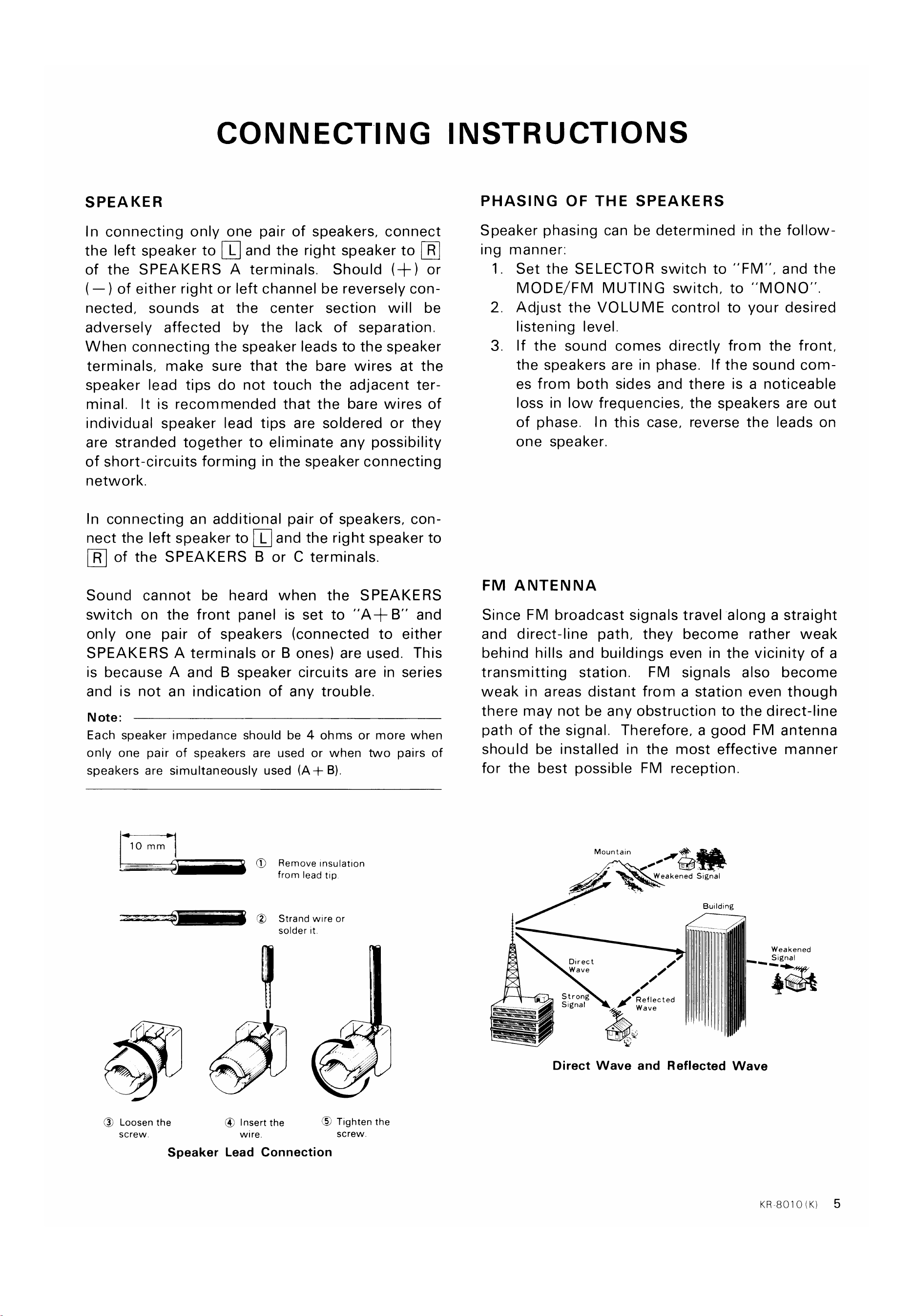
10 mm
(S)
Remove Insulation
from lead tip
Strand wire or
solder it.
FM ANTENNA
Since FM broadcast signals travel along a straight
and direct-line path, they become rather weak
behind hills and buildings even in the vicinity of a
transmitting station. FM signals also become
weak in areas distant from a station even though
there may not be any obstruction to the direct-line
path of the signal. Therefore, a good FM antenna
should be installed in the most effective manner
for the best possible FM reception.
Mountain
Weakened Signal
Building
Direct
W ave
S t r ong
Signal
Signal
Reflected
Wave
@ Loosen the
screw
@ Insert the
wire.
Tighten the
screw.
Speaker Lead Connection
Direct Wave and Reflected Wave
KR8010(K)
5
www.hifiengine.com
CONNECTING INSTRUCTIONS
Improper setting will adversely affect the high
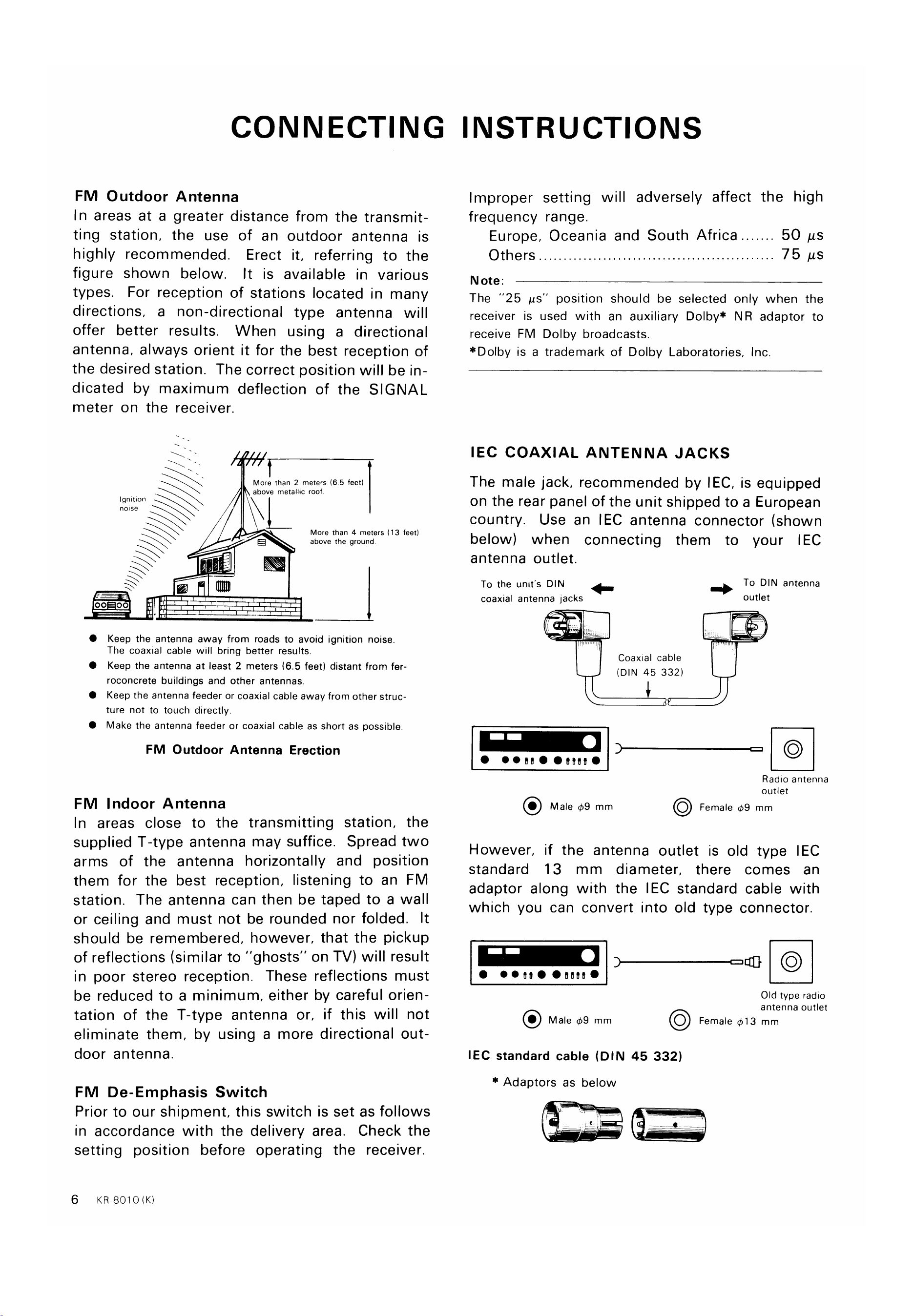
FM Outdoor Antenna
In areas at a greater distance from the transmit-
ting station, the use of an outdoor antenna is
highly recommended. Erect it, referring to the
figure shown below. It is available in various
types. For reception of stations located in many
directions, a non-directional type antenna will
offer better results. When using a directional
antenna, always orient it for the best reception of
the desired station. The correct position will be in-
dicated by maximum deflection of the SIGNAL
meter on the receiver.
More than 2 meters (6.5 feet)
above metallic roof.
frequency range.
Europe, Oceania and South Africa
Others
Note:
50 us
75 us
Ignition
notse
0 00
More than 4 meters (13 feet)
above the ground
The "25 AS" position should be selected only when the
receiver is used with an auxiliary Dolby* NR adaptor to
receive FM Dolby broadcasts.
*Dolby is a trademark of Dolby Laboratories, Inc.
IEC COAXIAL ANTENNA JACKS
The male jack, recommended by IEC, is equipped
on the rear panel of the unit shipped to a European
country. Use an IEC antenna connector (shown
below) when connecting them to your IEC
antenna outlet.
To the unit's DIN
coaxial antenna jacks
Male +9 mm
To DIN antenna
outlet
FM
Keep the antenna away from roads to avoid ignition noise.
The coaxial cable will bring better results.
Keep the antenna at least 2 meters (6.5 feet) distant from fer-
roconcrete buildings and other antennas.
Keep the antenna feeder or coaxial cable away from other struc-
ture not to touch directly.
Make the antenna feeder or coaxial cable as short as possible.
FM Outdoor Antenna Erection
Indoor Antenna
Coaxial cable
(DIN 45 332)
Radio antenna
outlet
O Female 09 mm
In areas close to the transmitting station, the
supplied T-type antenna may suffice. Spread two
arms of the antenna horizontally and position
them for the best reception, listening to an FM
station. The antenna can then be taped to a wall
or ceiling and must not be rounded nor folded. It
should be remembered, however, that the pickup
of reflections (similar to "ghosts" on TV) will result
in poor stereo reception. These reflections must
be reduced to a minimum, either by careful orien-
tation of the T-type antenna or, if this will not
eliminate them, by using a more directional out-
door antenna.
FM De-Emphasis Switch
Prior to our shipment, this switch is set as follows
in accordance with the delivery area. Check the
setting position before operating the receiver.
6 KR-8010 (K)
However, if the antenna outlet is old type IEC
standard 13 mm diameter, there comes an
adaptor along with the IEC standard cable with
which you can convert into old type connector.
Old type radio
antenna outlet
Female 13 mm
Male 09 mm
IEC standard cable (DIN 45 332)
* Adaptors as below
www.hifiengine.com
CONNECTING INSTRUCTIONS
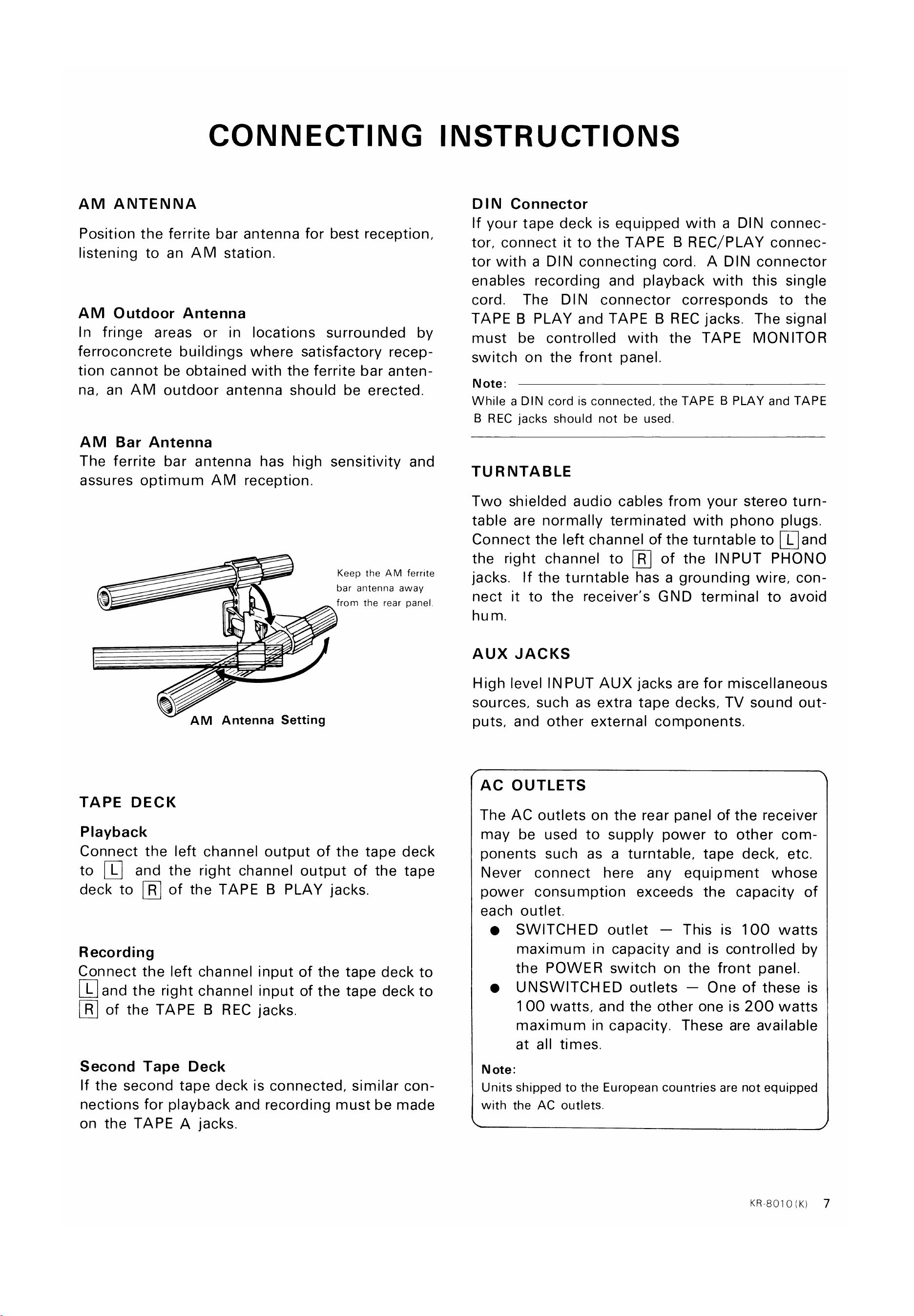
AM ANTENNA
Position the ferrite bar antenna for best reception,
listening to an AM station.
AM Outdoor Antenna
In fringe areas or in locations surrounded by
ferroconcrete buildings where satisfactory recep-
tion cannot be obtained with the ferrite bar anten-
na, an AM outdoor antenna should be erected
AM Bar Antenna
The ferrite bar antenna has high sensitivity and
assures optimum AM reception.
Keep the AM ferrite
bar antenna away
from the rear panel.
AM Antenna Setting
TAPE DECK
Playback
Connect the left channel output of the tape deck
to [U and the right channeloutput of the tape
deck to @ of the TAPE B PLAYjacks.
Recording
Connect the left channel input of the tape deck to
@and the rightchannelinputof the tapedeckto
@ of the TAPE B RECjacks.
Second Tape Deck
If the second tape deck is connected, similar con-
nections for playback and recording must be made
on the TAPE A jacks.
DIN Connector
If your tape deck is equipped with a DIN connec-
tor, connect it to the TAPE B REC/PLAY connec-
tor with a DIN connecting cord. A DIN connector
enables recording and playback with this single
cord. The DIN connector corresponds to the
TAPE B PLAY and TAPE B REC jacks. The signal
must be controlled with the TAPE MONITOR
switch on the front panel.
Note:
While a DIN cord is connected, the TAPE B PLAY and TAPE
B REC jacks should not be used
TURNTABLE
Two shielded audio cables from your stereo turn-
table are normally terminated with phono plugs.
Connectthe left channelof the turntableto [Qand
the right channel to [D of the INPUT PHONO
jacks. If the turntable has a grounding wire, con-
nect it to the receiver's GND terminal to avoid
hu m.
AUX JACKS
High level INPUT AUX jacks are for miscellaneous
sources, such as extra tape decks, TV sound out-
puts, and other external components.
AC OUTLETS
The AC outlets on the rear panel of the receiver
may be used to supply power to other com-
ponents such as a turntable, tape deck, etc.
Never connect here any equipment whose
power consumption exceeds the capacity of
each outlet.
SWITCHED outlet — This is 100 watts
maximum in capacity and is controlled by
the POWER switch on the front panel.
UNSWITCHED outlets — One of these is
1 00 watts, and the other one is 200 watts
maximum in capacity. These are available
at all times.
N ote:
Units shipped to the European countries are not equipped
with the AC outlets.
KR-8010<K)
7
www.hifiengine.com
CONTROLS AND FUNCTIONS
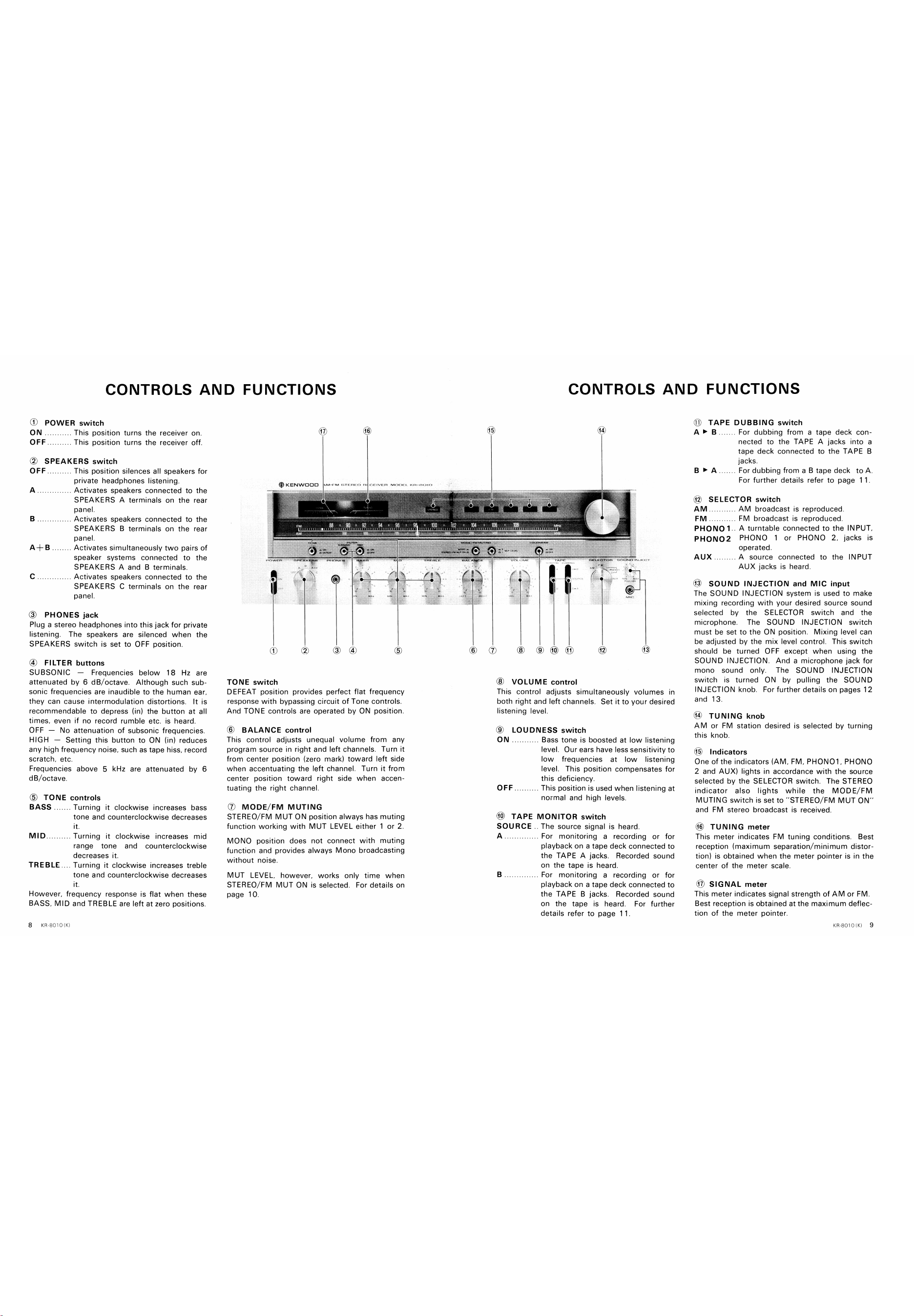
0) POWER switch
88
A+B
ON
OFF
This position turns the receiver on.
This position turns the receiver Off.
SPEAKERS switch
OFF
KENWOOD
CONTROLS AND FUNCTIONS
TAPE DUBBING switch
. For dubbing from a tape deck con-
nected to the TAPE A jacks into a
tape deck connected to the TAPE B
jacks.
For dubbing from a B tape deck to A.
For further details refer to page 1 1
SELECTOR switch
c
(3)
This position silences all speakers for
private headphones listening.
Activates speakers connected to the
SPEAKERS A terminals on the rear
panel.
Activates speakers connected to the
SPEAKERS B terminals on the rear
panel.
Activates simultaneously two pairs Of
speaker systems connected to the
SPEAKERS A and B terminals.
Activates speakers connected to the
SPEAKERS C terminals on the rear
panel.
AM
PHONO 1
PHON02
AUX
AM broadcast is reproduced
FM broadcast is reproduced
A turntable connected to the INPUT,
PHONO 1 or PHONO 2, jacks is
operated.
. A source connected to the INPUT
AUX jacks is heard.
PHONES jack
Plug a stereo headphones into this jack for private
listening. The speakers are silenced when the
SPEAKERS switch is set to OFF position.
(4) FILTER buttons
SUBSONIC —
Frequencies below 18 Hz are
attenuated by 6 dB/octave. Although such sub-
sonic frequencies are inaudible to the human ear,
they can cause intermodulation distortions. It is
recommendable to depress (in) the button at all
times. even if no record rumble etc. is heard.
OFF —
No attenuation of subsonic frequencies.
HIGH —
Setting this button to ON (in) reduces
any high frequency noise, such as tape hiss, record
scratch, etc.
Frequencies above 5 kHz are attenuated by 6
dB/octave.
(b) TONE controls
(f)
TONE switch
DEFEAT position provides perfect flat
(5)
frequency
BASS
MID
Turning it clockwise increases bass
tone and counterclockwise decreases
it.
Turning it clockwise increases mid
range tone and counterclockwise
decreases it.
TREBLE Turning it clockwise increases treble
tone and counterclockwise decreases
it.
However, frequency response is flat when these
BASS, MID and TREBLE are left at zero positions.
response with bypassing circuit of Tone controls.
And TONE controls are operated by ON position.
@ BALANCE control
This control adjusts unequal volume from any
program source in right and left channels. Turn it
from center position (zero mark) toward left side
when accentuating the left channel. Turn it from
center position toward right side when accen-
tuating the right channel.
(j) MODE/FM MUTING
STEREO/ FM MUT ON position always has muting
function working with MUT LEVEL either 1 or 2.
MONO position does not connect with muting
function and provides always Mono broadcasting
without noise.
MUT LEVEL. however, works only time when
STEREO/FM MUT ON is selected. For details on
page 10.
@ VOLUME control
This control adjusts simultaneously volumes in
both right and left channels. Set it to your desired
listening level.
@ LOUDNESS switch
ON
Bass tone is boosted at low listening
level. Our ears have less sensitivity to
low frequencies at low listening
level. This position compensates for
this deficiency.
This position is used when listening at
normal and high levels,
@ TAPE MONITOR switch
SOURCE
The source signal is heard.
For monitoring a recording or for
playback on a tape deck connected to
the TAPE A jacks. Recorded sound
on the tape is heard.
For monitoring a recording or for
playback on a tape deck connected to
the TAPE B jacks. Recorded sound
on the tape is heard. For further
details refer to page I I.
@ SOUND INJECTION and MIC input
The SOUND INJECTION system is used to make
mixing recording with your desired source sound
selected by the SELECTOR switch and the
microphone. The SOUND INJECTION switch
must be set to the ON position. Mixing level can
be adjusted by the mix level control. This switch
should be turned OFF except when using the
SOUND INJECTION. And a microphone jack for
mono sound only. The SOUND INJECTION
switch is turned ON by pulling the SOUND
INJECTION knob. For further details on pages 12
and 13.
@ TUNING knob
AM or FM station desired is selected by turning
this knob.
($6) Indicators
one of the indicators (AM, FM, PHONOI , PHONO
2 and AIJX) lights in accordance with the source
selected by the SELECTOR switch. The STEREO
indicator also lights while the MODE/FM
MUTING switch is set to "STEREO/FM MUT ON'
and FM stereo broadcast is received.
TUNING meter
This meter indicates FM tuning conditions. Best
reception (maximum separation/minimum distor-
tion) is obtained when the meter pointer is in the
center of the meter scale.
SIGNAL meter
This meter indicates signal strength of AM or FM
Best reception is obtained at the maximum deflec-
tion of the meter pointer.
www.hifiengine.com
OPERATING INSTRUCTIONS
Explanations of each function
Prior to turning on the receiver, set each control
As for functions of this switch, there are two
and switch as below.
e VOLUME
e TAPE MONITOR,
DUBBING
SELECTOR
MODE/FM MUTING
MUT LEVEL
BALANCE, BASS,
MID and TREBLE
MIN
SOURCE
STEREO/FM
MUT ON
1
Center position
Next,
turn on the receiver and set the
SPEAKERS switch to "OFF" (PHONES),
'B", ' 'A4- B" or "C" in accordance with the item
to be operated.
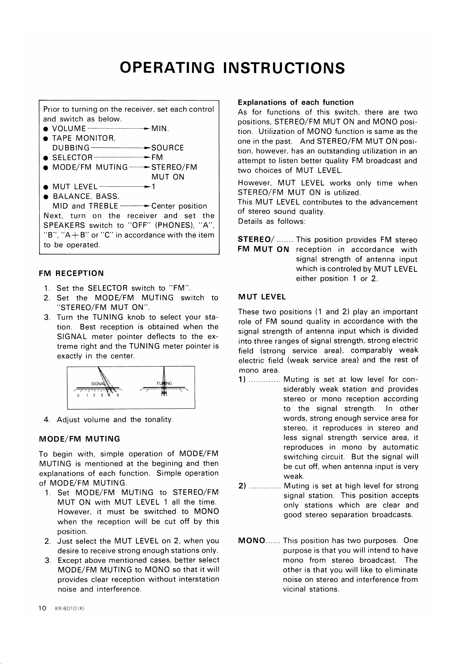
FM RECEPTION
Set the SELECTOR switch to "FM'
set the MODE/FM MUTING switch to
"STEREO/FM MUT ON"
Turn the TUNING knob to select your sta-
tion. Best reception is obtained when the
SIGNAL meter pointer deflects to the ex-
treme right and the TUNING meter pointer is
1
2.
3.
4.
exactly in the center.
SIGNA
01 23
5
positions, STEREO/FM MUT ON and MONO posi-
tion. Utilization of MONO function is same as the
one in the past. And STEREO/ FM MUT ON posi-
tion, however, has an outstanding utilization in an
attempt to listen better quality FM broadcast and
two choices of MUT LEVEL.
However, MUT LEVEL works only time when
STEREO/FM MUT ON is utilized.
This MUT LEVEL contributes to the advancement
of stereo sound quality.
Details as follows:
STEREO
This position provides FM stereo
FM MUT ON reception in accordance with
signal strength of antenna input
which is controled by MUT LEVEL
either position 1 or 2.
MUT LEVEL
These two positions (1 and 2) play an important
role of FM sound quality in accordance with the
signal strength of antenna input which is divided
into three ranges of signal strength, strong electric
field (strong service area), comparably weak
electric field (weak service area) and the rest of
mono area.
T NG
Adjust volume and the tonality.
MODE/FM MUTING
To begin with, simple operation of MODE/ FM
MUTING is mentioned at the begining and then
explanations of each function. Simple operation
of MODE/FM MUTING.
1.
2.
3
10
set MODE/FM MUTING to STEREO/FM
MUT ON with MUT LEVEL 1 all the time.
However, it must be switched to MONO
when the reception will be cut off by this
position.
Just select the MUT LEVEL on 2, when you
desire to receive strong enough stations only.
Except above mentioned cases, better select
MODE/FM MUTING to MONO so that it will
provides clear reception without interstation
noise and interference.
KR8010(K)
1)
2)
MONO
Muting is set at low level for con-
siderably weak station and provides
stereo or mono reception according
to the signal strength.
In other
words, strong enough service area for
stereo, it reproduces in stereo and
less signal strength service area, it
reproduces in mono by automatic
switching circuit. But the signal will
be cut off, when antenna input is very
weak.
Muting is set at high level for strong
signal station. This position accepts
only stations which are clear and
good stereo separation broadcasts.
This position has two purposes. One
purpose is that you will intend to have
mono from stereo broadcast. The
other is that you will like to eliminate
noise on stereo and interference from
vicinal stations.
www.hifiengine.com
OPERATING INSTRUCTIONS
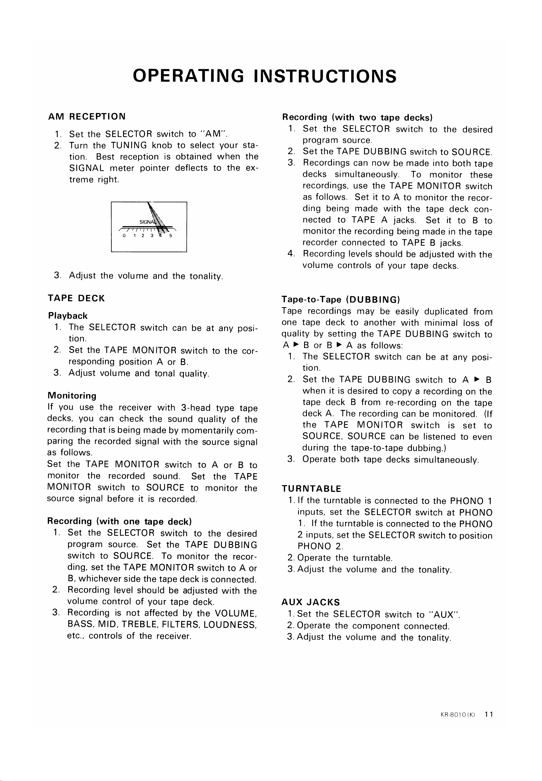
AM RECEPTION
1. Set the SELECTOR switch to "AM"
2. Turn the TUNING knob to select your sta
tion. Best reception is obtained when
the
SIGNAL meter pointer deflects to the
treme right.
SIGNA
01 23 5
3. Adjust the volume and the tonality.
TAPE DECK
Playback
1. The SELECTOR switch can be at any posi-
tion.
2. Set the TAPE MONITOR switch to the cor-
responding position A or B.
3. Adjust volume and tonal quality.
Monitoring
If you use the receiver with 3-head type tape
decks, you can check the sound quality of the
recording that is being made by momentarily com-
paring the recorded signal with the source signal
as follows.
Set the TAPE MONITOR switch to A or B to
monitor the recorded sound. Set the TAPE
MONITOR switch to SOURCE to monitor the
source signal before it is recorded.
Recording (with one tape deck)
Recording (with two tape decks)
1. Set the SELECTOR switch to the desired
program source.
2. Set the TAPE DUBBING switch to SOURCE.
3. Recordings can now be made into both tape
decks simultaneously. To monitor these
recordings, use the TAPE MONITOR switch
as follows. Set it to A to monitor the recor-
ding being made with the tape deck con-
nected to TAPE A jacks. Set it to B to
monitor the recording being made in the tape
recorder connected to TAPE B jacks.
4. Recording levels should be adjusted with the
volume controls of your tape decks.
Tape-to-Tape (DUBBING)
Tape recordings may be easily duplicated from
one tape deck to another with minimal loss of
quality by setting the TAPE DUBBING switch to
A B or B A as follows:
1. The SELECTOR switch can be at any posi-
tion.
2. Set the TAPE DUBBING switch to A B
when it is desired to copy a recording on the
tape deck B from re-recording on the tape
deck A. The recording can be monitored. (If
the TAPE MONITOR switch is set to
SOURCE, SOURCE can be listened to even
during the tape-to-tape dubbing.)
3. Operate both tape decks simultaneously.
TURNTABLE
1. If the turntable is connected to the PHONO 1
inputs, set the SELECTOR switch at PHONO
1
If the turntable is connected to the PHONO
2 inputs, set the SELECTOR switch to position
1
2.
3.
Set the SELECTOR switch to the desired
program source. Set the TAPE DUBBING
switch to SOURCE. To monitor the recor-
ding, set the TAPE MONITOR switch to A or
B, whichever side the tape deck is connected.
Recording level should be adjusted with the
volume control of your tape deck.
Recording is not affected by the VOLUME,
BASS, MID, TREBLE, FILTERS, LOUDNESS,
etc., controls of the receiver.
pHONO 2.
2. Operate the turntable.
3. Adjust the volume and the tonality.
AUX JACKS
1. Set the SELECTOR switch to "AUX"
2. Operate the component connected.
3. Adjust the volume and the tonality.
KR8010(K)
11
www.hifiengine.com
OPERATING INSTRUCTIONS
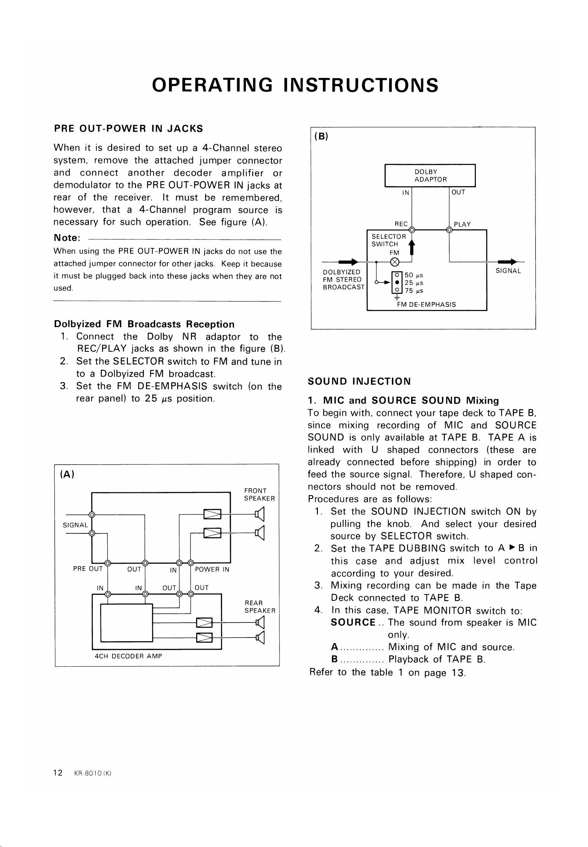
PRE OUT-POWER IN JACKS
When it is desired to set up a 4-Channel stereo
system, remove the attached jumper connector
and connect another decoder amplifier or
demodulator to the PRE OUT-POWER IN jacks at
rear of the receiver.
It must be remembered,
however, that a 4-Channel program source is
necessary for such operation. See figure (A).
Note:
When using the PRE OUT-POWER IN jacks do not use the
attached jumper connector for other jacks. Keep it because
it must be plugged back into these jacks when they are not
used.
Dolbyized FM Broadcasts Reception
(B)
DOLBY
ADAPTOR
IN
REC
o
SELECTOR
SWITCH
DOLBYIZED
0 50 gs
FM STEREO
25 us
BROADCAST
0 75 gs
OUT
PLAY
o
SIGNAL
1
2.
3.
Connect the Dolby NR adaptor to the
REC/PLAY jacks as shown in the figure (B).
Set the SELECTOR switch to FM and tune in
to a Dolbyized FM broadcast.
Set the FM DE-EMPHASIS switch (on the
rear panel) to 25 us position.
-FM DE-EMPHASIS
SOUND INJECTION
1. MIC and SOURCE SOUND Mixing
To begin with, connect your tape deck to TAPE B,
since mixing recording of MIC and SOURCE
SOUND is only available at TAPE B. TAPE A is
linked with U shaped connectors (these are
already connected before shipping) in order to
feed the source signal. Therefore, U shaped con-
nectors should not be removed
Procedures are as follows:
o
SIGNAL
o
o
PRE OUT
IN
o
o
OUT
IN
o
o
OUT
o
o
POWER IN
OUT
o
FRONT
SPEAKER
REAR
SPEAKER
1
2.
3.
4.
Set the SOUND INJECTION switch ON by
pulling the knob. And select your desired
source by SELECTOR switch.
set the TAPE DUBBING switch to A > B in
this case and adjust mix level control
according to your desired.
Mixing recording can be made in the Tape
Deck connected to TAPE B
In this case, TAPE MONITOR switch to.
SOURCE. The sound from speaker is MIC
only.
Mixing of MIC and source.
Playback of TAPE B
12
4CH DECODER AMP
KR-8010 (K)
Refer to the table 1 on page 13.
www.hifiengine.com
OPERATING INSTRUCTIONS
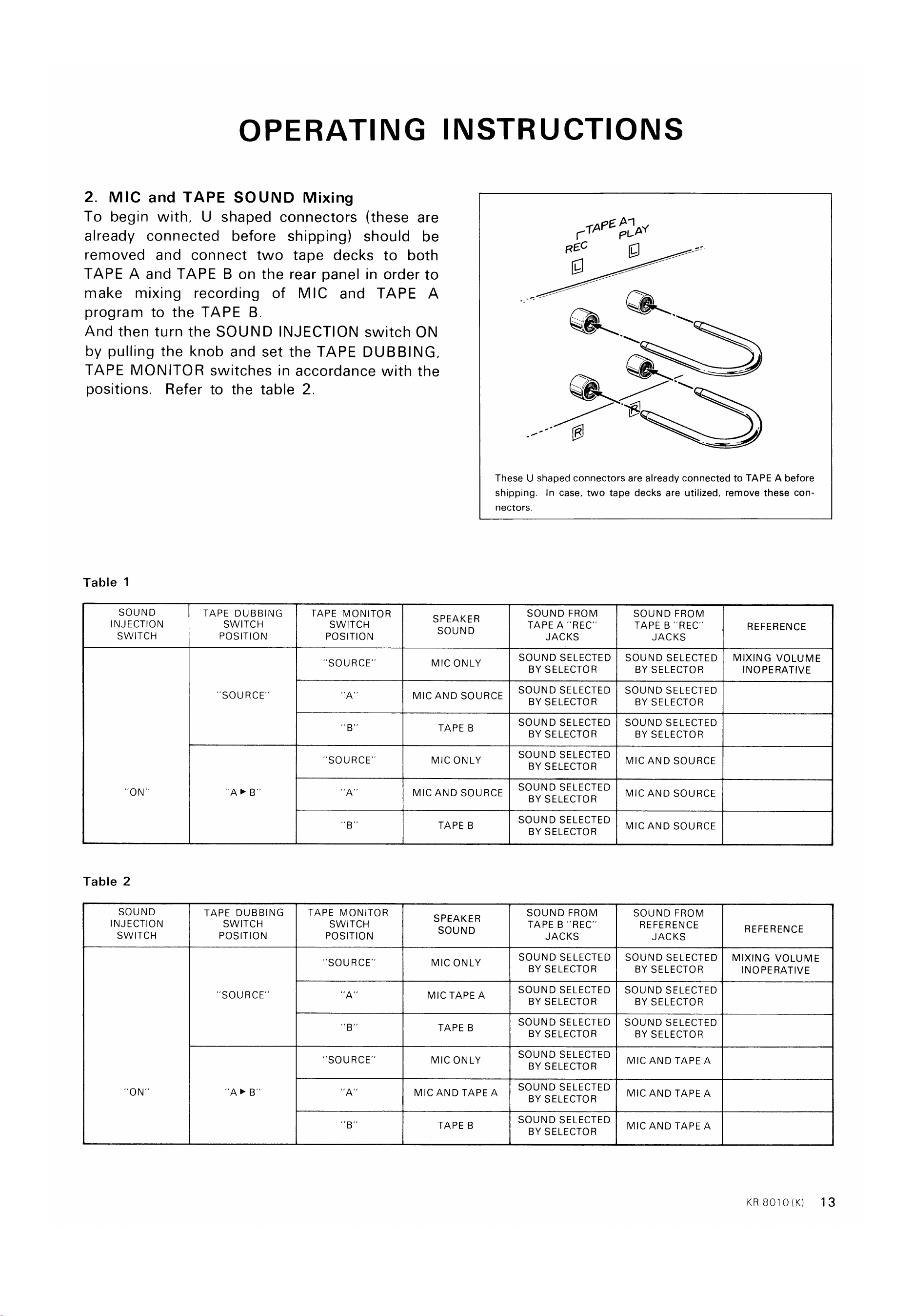
2. MIC and TAPE SOUND Mixing
To begin with, U shaped connectors (these are
already connected before shipping) should be
removed and connect two tape decks to both
TAPE A and TAPE B on the rear panel in order to
make mixing recording of MIC and TAPE A
program to the TAPE B
And then turn the SOUND INJECTION switch ON
by pulling the knob and set the TAPE DUBBING,
TAPE MONITOR switches in accordance with the
positions. Refer to the table 2.
TAPEA-1
PLAY
REC
These U shaped connectors are already connected to TAPE A before
shipping. In case, two tape decks are utilized, remove these con-
Table 1
SOUND
INJECTION
SWITCH
Table 2
SOUND
INJECTION
SWITCH
ON'
TAPE DUBBING
SWITCH
POSITION
'SOURCE'
TAPE DUBBING
SWITCH
POSITION
"SOURCE"
TAPE MONITOR
SWITCH
POSITION
"SOURCE'
'SOURCE"
B'
TAPE MONITOR
SWITCH
POSITION
'SOURCE'
'SOURCE"
"A'
SPEAKER
SOUND
MIC ONLY
nectors.
SOUND FROM
TAPE A "REC'
JACKS
SOUND SELECTED
BY SELECTOR
SOUND SELECTED
MIC AND SOURCE
TAPE B
MIC ONLY
MIC AND SOURCE
SPEAKER
SOUND
MIC ONLY
MIC TAPE A
TAPE B
MIC ONLY
MIC AND TAPE A
TAPE B
BY SELECTOR
SOUND SELECTED
BY SELECTOR
SOUND SELECTED
BY SELECTOR
SOUND SELECTED
BY SELECTOR
SOUND SELECTED
BY SELECTOR
SOUND FROM
TAPE B "REC'
JACKS
SOUND SELECTED
BY SELECTOR
SOUND SELECTED
BY SELECTOR
SOUND SELECTED
BY SELECTOR
SOUND SELECTED
BY SELECTOR
SOUND SELECTED
BY SELECTOR
SOUND SELECTED
BY SELECTOR
SOUND FROM
TAPE B "REC
JACKS
SOUND SELECTED
BY SELECTOR
SOUND SELECTED
BY SELECTOR
SOUND SELECTED
BY SELECTOR
MIC AND SOURCE
MIC AND SOURCE
MIC AND SOURCE
SOUND FROM
REFERENCE
JACKS
SOUND SELECTED
BY SELECTOR
SOUND SELECTED
BY SELECTOR
SOUND SELECTED
BY SELECTOR
MIC AND TAPE A
MIC AND TAPE A
MIC AND TAPE A
REFERENCE
MIXING VOLUME
INOPERATIVE
REFERENCE
MIXING VOLUME
INOPERATIVE
KR-8010(K)
13
www.hifiengine.com
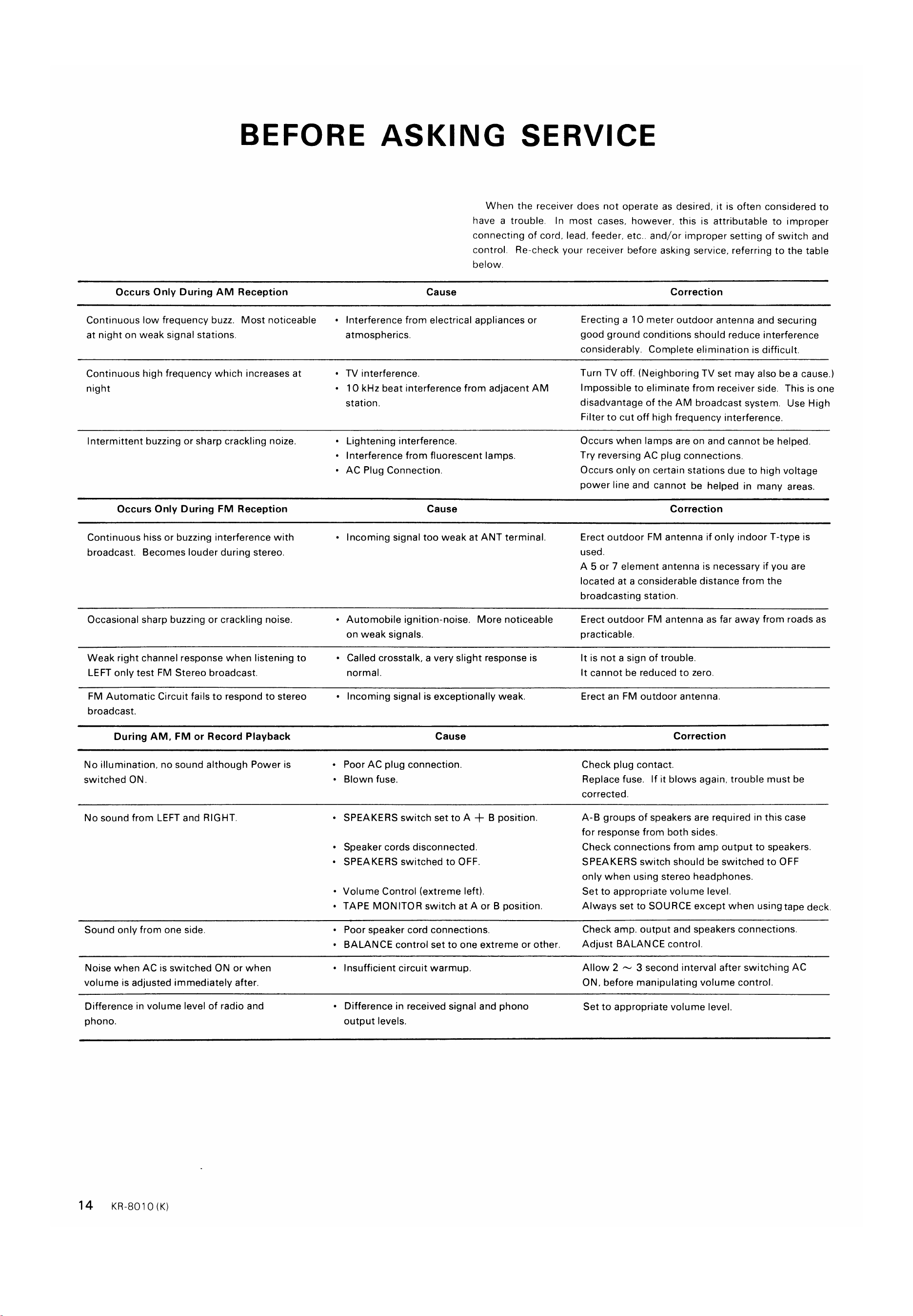
BEFORE ASKING SERVICE
When the receiver does not operate as desired, it is often considered to
have a trouble. In most cases. however. this is attributable to improper
connecting of cord, lead. feeder. etc.. and/or improper setting of switch and
control. Re-check your receiver before asking service. referring to the table
below.
Cause
Occurs Only During AM Reception
Continuous low frequency buzz. Most noticeable
at night on weak signal stations.
Continuous high frequency which increases at
night
Intermittent buzzing or sharp crackling noize.
Occurs Only During FM Reception
Continuous hiss or buzzing interference with
broadcast. Becomes louder during stereo.
Occasional sharp buzzing or crackling noise.
Weak right channel response when listening to
LEFT only test FM Stereo broadcast.
FM Automatic Circuit fails to respond to stereo
broadcast.
During AM, FM or Record Playback
No illumination, no sound although Power is
switched ON
No sound from LEFT and RIGHT.
Sound only from one side.
Noise when AC is switched ON or when
volume is adjusted immediately after.
Difference in volume level of radio and
phono.
Interference from electrical appliances or
•
atmospherics.
• TV interference.
• I O kHz beat interference from adjacent AM
station.
Lightening interference.
Interference from fluorescent lamps.
•
• AC Plug Connection.
Cause
Incoming signal too weak at ANT terminal.
•
Automobile ignition-noise. More noticeable
•
on weak signals.
Called crosstalk. a very slight response is
•
normal.
Incoming signal is exceptionally weak.
•
Cause
Poor AC plug connection.
•
Blown fuse,
•
• SPEAKERS switch set to A -+- B position.
Speaker cords disconnected.
• SPEAKERS switched to OFF.
Volume Control (extreme left).
•
• TAPE MONITOR switch at A or B position.
Poor speaker cord connections,
•
• BALANCE control set to one extreme or other.
Insufficient circuit warmup.
Difference in received signal and phono
output levels.
Correction
Erecting a 10 meter outdoor antenna and securing
good ground conditions should reduce interference
considerably. Complete elimination is difficult.
Turn TV off. (Neighboring TV set may also bea cause.)
Impossible to eliminate from receiver side. This is one
disadvantage of the AM broadcast system. Use High
Filter to cut off high frequency interference.
Occurs when lamps are on and cannot be helped.
Try reversing AC plug connections.
Occurs only on certain stations due to high voltage
power line and cannot be helped in many areas.
Correction
Erect outdoor FM antenna if only indoor T-type is
used.
A 5 or 7 element antenna is necessary if you are
located at a considerable distance from the
broadcasting station.
Erect outdoor FM antenna as far away from roads as
practicable.
It is not a sign of trouble.
It cannot be reduced to zero.
Erect an FM outdoor antenna.
Correction
Check plug contact.
Replace fuse. If it blows again, trouble must be
corrected.
A-B groups of speakers are required in this case
for response from both sides.
Check connections from amp output to speakers.
SPEAKERS switch should be switched to OFF
only when using stereo headphones.
Set to appropriate volume level.
Always set to SOURCE except when using tape deck.
Check amp. output and speakers connections.
Adjust BALANCE control.
Allow 2 3 second interval after switching AC
ON, before manipulating volume control.
Set to appropriate volume level.
14
KR-8010 (K)
www.hifiengine.com
BEFORE ASKING SERVICE
Cause
During Phono Record Playbacks Only
No sound from LEFT and RIGHT. or sound
only from one side.
Loud hum drowns out sound.
Sound audible but background hum occurs.
Sound audible but continuous background
buzz interference.
Howling noise occurs when volume is raised
•
•
•
•
•
IF AMP
Turntable output disconnected.
Poor turntable output cord prong connections.
Turntable output cord picking up hum from
AC cord.
Turntable not grounded.
• TV signal picked up by Turntable output cord.
Frequency occurs near TV transmitting antenna.
Speaker vibrations induce feedback in Pickup.
Correction
See that turntable output cord is firmly plugged
into amp. input.
See that turntable output cord is firmly plugged
into amp. input.
Keep turntable output cord away from AC cord.
Choose cord paths which keep hum at a minimum.
Twist LEFT RIGHT turntable output cords together.
Reverse turntable AC plug connections.
Connect ground wire to GND terminal.
Route turntable cord so that hum is minimized.
Increase distance between turntable and speakers.
Choose speaker locations carefully.
Remember. loose flooring induces howling
or bass response is increased.
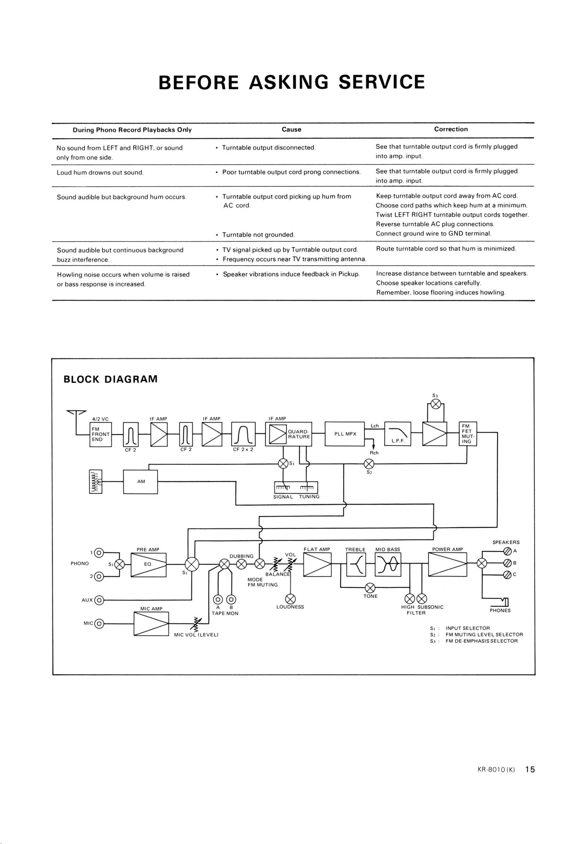
BLOCK DIAGRAM
4/2 VC
FRONT
END
IF AMP
AM
PRE AMP
MIC AMP
IF AMP
CF 2
Lch
QUARD.
PLL MPX
RATURE
L.P.F.
Rch
CF 2x2
DUBBING
SIGNAL
VOL
BALANCE
TUNING
FLAT AMP
TREBLE
MID BASS
FET
MUT.
ING
POWER AMP
PHONO
AUX O
MIC O
MODE
FM MUTING
LOUDNESS
TONE
HIGH SUBSONIC
FILTER
SPEAKERS
c
PHONES
TAPE MON
MIC VOL (LEVEL)
INPUT SELECTOR
FM MUTING LEVEL SELECTOR
FM DE-EMPHASIS SELECTOR
KR-8010 (K)
15
www.hifiengine.com
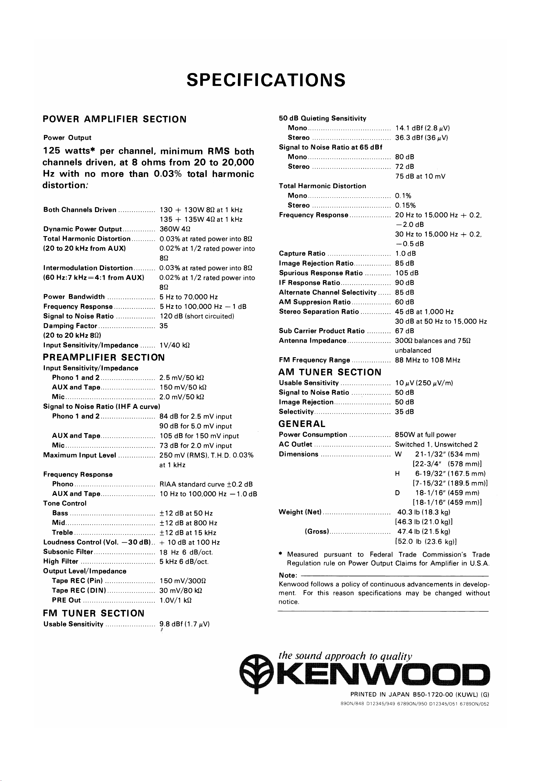
SPECIFICATIONS
POWER AMPLIFIER SECTION
Power Output
125 watts* per channel, minimum RMS both
channels driven, at 8 ohms from 20 to 20,000
Hz with no more than 0.03% total harmonic
distortion:
Both Channels Driven
Dynamic Power Output
Total Harmonic Distortion
(20 to 20 kHz from
Intermodulation Distortion
(60 Hz:7 from AUX)
Power Bandwidth
Frequency Response
Signal to Noise Ratio
Damping Factor
(20 to 20 kHz 80)
Input Sensitivity/l m pedance
130 + 130W 80 at 1 kHz
135 + 135W 4Qat 1 kHz
360W 40
0.03% at rated power into 80
0.02% at 1/2 rated power into
80
0.03% at rated power into 80
0.02% at 1/2 rated power into
80
5 Hz to 70,000 Hz
5 to 100,000 Hz —1 dB
120 dB (short circuited)
35
1V/40 kS2
PREAMPLIFIER SECTION
Input Sensitivity/l m pedance
Phono 1 and 2
AUX and Tape
Mic
2.5 mV/50
150 mV/50
2.0 mV/50 kQ
Signal to Noise Ratio (IHF A curve)
50 dB Quieting Sensitivity
Mono
Stereo
Signal to Noise Ratio at 65 dBf
M ono
Stereo
Total Harmonic Distortion
Mono
Stereo
Frequency Response
Capture Ratio
Image Rejection Ratio
Spurious Response Ratio
IF Response Ratio
Alternate Channel Selectivity
AM Suppresion Ratio
Stereo Separation Ratio
Sub Carrier Product Ratio
Antenna Impedance
FM Frequency Range
AM TUNER SECTION
Usable Sensitivity
Signal to Noise Ratio
Image Rejection.
Selectivity
GENERAL
Power Consumption
AC Outlet
Dimensions
Weight (Net)
(Gross)
14.1 dBf (2.8
36.3 dBf (36
80 dB
72 dB
75 dB at 10 mV
o. 15%
20 Hz to 15,000 Hz + 0.2,
—2.0 dB
30 Hz to 15.000 Hz + 0.2.
—0.5dB
1.0 dB
85 dB
105 dB
90 dB
85 dB
60 dB
45 dB at 1,000 Hz
30 dB at 50 Hz to 15,000 Hz
67 dB
3009 balances and 750
unbalanced
88 MHz to 108 MHz
10 gv (250 mm)
50 dB
50 dB
35 dB
850W at full power
Switched 1, Unswitched 2
Phono 1 and 2
AUX and Tape
Mic.
Maximum Input Level
Frequency Response
Phono
AUX and Tape
Tone Control
Bass
Mid
Treble
Loudness Control (Vol.
Subsonic Filter
High Filter
—30 dB).
84 dB for 2.5 mV input
90 dB for 5.0 mV input
105 dB for 150 mV input
73 dB for 2.0 mV input
250 mv (RMS), T.H.D. 0.03%
at 1 kHz
RIAA standard curve ±0.2 dB
10 Hzto 100.000 Hz —1.0 dB
±12dB at 50 Hz
dB at 800 Hz
±12dB at 15 kHz
+ 10 dB at 100 Hz
18 Hz 6 dB/oct.
5 kHz 6 dB/oct.
150 mV/300Q
30 mV/80
I.OV/I kQ
9.8 dBf(1.7 N)
w
H
D
21-1/32" (534 mm)
[22-3/4" (578 mm))
6-19/32" (167.5 mm)
[7-15/32" (189.5 mm)]
18-1/16" (459 mm)
[18-1/16" (459 mm)]
40.3 lb (18.3 kg)
[46.3 lb (21.0 kg)l
47.4 lb (21.5 kg)
[52.0 lb (23.6 kg)]
Output Level/l mpedance
Tape REC (Pin)
Tape REC (DIN)
PRE Out
FM TUNER SECTION
Usable Sensitivity
* Measured pursuant to Federal Trade Commission's Trade
Regulation rule on Power Output Claims for Amplifier in U.S.A
Note:
Kenwood follows a policy of continuous advancements in develop-
ment. For this reason specifications may be changed without
notice.
the sound approach to quality
OKENWOOD
PRINTED IN JAPAN 850-1720-00 (KUWL) (G)
890N/848 012345/949 67890N/950 [)12345/051 67890N/052